EP3089283A1 - Coiling device and household appliance having the same - Google Patents
Coiling device and household appliance having the same Download PDFInfo
- Publication number
- EP3089283A1 EP3089283A1 EP14873171.4A EP14873171A EP3089283A1 EP 3089283 A1 EP3089283 A1 EP 3089283A1 EP 14873171 A EP14873171 A EP 14873171A EP 3089283 A1 EP3089283 A1 EP 3089283A1
- Authority
- EP
- European Patent Office
- Prior art keywords
- coiling
- segment
- power cord
- bobbin
- housing
- Prior art date
- Legal status (The legal status is an assumption and is not a legal conclusion. Google has not performed a legal analysis and makes no representation as to the accuracy of the status listed.)
- Granted
Links
Images


Classifications
-
- H—ELECTRICITY
- H01—ELECTRIC ELEMENTS
- H01R—ELECTRICALLY-CONDUCTIVE CONNECTIONS; STRUCTURAL ASSOCIATIONS OF A PLURALITY OF MUTUALLY-INSULATED ELECTRICAL CONNECTING ELEMENTS; COUPLING DEVICES; CURRENT COLLECTORS
- H01R13/00—Details of coupling devices of the kinds covered by groups H01R12/70 or H01R24/00 - H01R33/00
- H01R13/72—Means for accommodating flexible lead within the holder
-
- H—ELECTRICITY
- H02—GENERATION; CONVERSION OR DISTRIBUTION OF ELECTRIC POWER
- H02G—INSTALLATION OF ELECTRIC CABLES OR LINES, OR OF COMBINED OPTICAL AND ELECTRIC CABLES OR LINES
- H02G11/00—Arrangements of electric cables or lines between relatively-movable parts
- H02G11/02—Arrangements of electric cables or lines between relatively-movable parts using take-up reel or drum
-
- H—ELECTRICITY
- H01—ELECTRIC ELEMENTS
- H01R—ELECTRICALLY-CONDUCTIVE CONNECTIONS; STRUCTURAL ASSOCIATIONS OF A PLURALITY OF MUTUALLY-INSULATED ELECTRICAL CONNECTING ELEMENTS; COUPLING DEVICES; CURRENT COLLECTORS
- H01R24/00—Two-part coupling devices, or either of their cooperating parts, characterised by their overall structure
- H01R24/28—Coupling parts carrying pins, blades or analogous contacts and secured only to wire or cable
- H01R24/30—Coupling parts carrying pins, blades or analogous contacts and secured only to wire or cable with additional earth or shield contacts
Definitions
- the invention relates to the field of household appliances, and in particular to a coiling device and a household appliance having same.
- Coiling devices are provided in a small number of household appliances in the prior art.
- it is necessary to adopt an elastic piece and contact structure to solve the problem of connection of a power supply for each of the coiling devices due to mutual conversion of the power cord between a straight line and a circumference, and a potential safety hazard is easily caused by the elastic piece and contact structure due to the problem of reliability.
- the invention aims to provide a coiling device and a household appliance having same, which are intended to improve use safety.
- the invention provides a coiling device, which is configured to coil a power cord.
- the power cord comprising a first segment and a second segment connected with each other.
- the coiling device comprises: a first coiling bobbin, provided with a first coiling groove, the first segment of the power cord being wound in the first coiling groove; and a second coiling bobbin, fixedly connected with the first coiling bobbin and provided with a second coiling groove, the second segment of the power cord being wound in the second coiling groove, and a winding direction of the second segment of the power cord being identical to that of the first segment of the power cord.
- the coiling device may further comprises a storage assembly, the storage assembly is provided with an accommodating cavity, and when the first segment of the power cord is pulled out of the first coiling bobbin, the second segment of the power cord enters the accommodating cavity from the second coiling groove.
- the storage assembly comprises a storage housing and a guide rail arranged therein, and the accommodating cavity is cooperatively formed by the guide rail and the storage housing.
- the second coiling bobbin is of an outer gear structure
- the storage assembly is of an inner gear structure
- the coiling device further comprises a transmission gear
- the transmission gear meshes with the second coiling bobbin and the storage assembly respectively.
- the coiling device further comprises a drive assembly in drive connection with the first coiling bobbin.
- the coiling device further comprises a housing, the first coiling bobbin is provided on the housing rotatably, and the drive assembly may be a coil spring mounted on the housing and connected with the first coiling bobbin.
- a first limiting portion is provided on the first coiling bobbin, and the coiling device further comprises a second limiting portion fitting with the first limiting portions to limit a rotation angle of the first coiling bobbin.
- the coiling device further comprising a housing
- the first coiling bobbin is provided on the housing rotatably
- the first limiting portion is a ratchet provided at the periphery of the first coiling bobbin
- the second limiting portion is a limiting block provided on the housing.
- a rotary shaft is provided on the housing
- the limiting block is provided on the rotary shaft rotatably
- the limiting block comprises a handle portion arranged outside the housing and a limiting end portion arranged inside the housing, the limiting end portion is matched with the ratchet in a clamping manner.
- the second limiting portion further comprises a spring, and the spring which is provided at the housing and is matched with the limiting end portion in a squeezing manner so as to allow the limiting end portion to be clamped with the ratchet under a normal state.
- the invention also provides a household appliance, comprising a power cord and an above-mentioned coiling device.
- the household appliance comprises an appliance housing, and the coiling device being detachably fixed to an interior of the appliance housing by screws.
- the first coiling bobbin and the second coiling bobbin are arranged, and the winding directions of the first segment and the second segment of the power cord are set to be identical.
- the first coiling bobbin drives the second coiling bobbin to rotate, and the second segment of the power cord is unwound from the second coiling groove accordingly, so that the power cord is prevented from being twisted at a point of connection between the first segment and the second segment, and therefore the aim of improving the use safety can be achieved without an elastic piece and contact structure.
- Drawing marks 10, first coiling bobbin; 11, first limiting portion; 20, second coiling bobbin; 30, storage assembly; 31, accommodating cavity; 32, storage housing; 33, guide rail; 40, transmission gear; 50, drive assembly; 60, housing; 61, limiting block; 611, handle portion; 612, limiting end portion; 62, spring; 63, rotary shaft; 64, mounting box; 65, mounting cover; 70, connecting shaft; 91, first segment; 92, second segment; and 93, third segment.
- an embodiment of the invention provides a coiling device, which is configured to coil a power cord.
- the power cord comprises a first segment 91, a second segment 92 and a third segment 93, connected with each other.
- the coiling device comprises a housing 60, a first coiling bobbin 10 and a second coiling bobbin 20, wherein the first coiling bobbin 10 and the second coiling bobbin 20 are provided inside the housing 60 rotatably.
- the first coiling bobbin 10 is provided with a first coiling groove, the first segment 91 of the power cord is wound in the first coiling groove, and one end, serving as a free end, of the first segment extends out of the housing 60.
- the second coiling bobbin 20 is fixedly connected with the first coiling bobbin 10, and the second coiling bobbin 20 is provided with a second coiling groove, the second segment 92 of the power cord is wound in the second coiling groove, and a winding direction of the second segment 92 of the power cord is identical to a winding direction of the first segment 91 of the power cord.
- the third segment 93 of the power cord is connected with the second segment 92 of the power cord, extends out of the housing 60, and is used as a connecting end of the power cord.
- the first coiling bobbin 10 and the second coiling bobbin 20 are provided, and the winding direction of the first segment 91 of the power cord and the winding direction of the second segment 92 of the power cord are set to be identical.
- the first coiling bobbin 10 drives the second coiling bobbin 20 to rotate, and the second segment 92 of the power cord is unwound from the second coiling groove accordingly, so that the power cord is prevented from being twisted at a point of connection between the first segment 91 of the power cord and the second segment 92 of the power cord, and therefore the aim of improving use safety can be achieved without an elastic piece and an contact structure.
- the first coiling bobbin 10 and the second coiling bobbin 20 in the embodiment of the invention are fixedly connected by a screw, the circles of the first coiling bobbin 10 and the second coiling bobbin 20 and the axis of the connecting shaft 70 are located on a straight line, and the first coiling bobbin 10 and the second coiling bobbin 20 rotate around the connecting shaft 70.
- a mounting hole is provided at the first coiling bobbin 10.
- a mounting column in fit connection with the mounting hole is provided at a side surface, opposite to the first coiling bobbin 10, of the second coiling bobbin 20. The screw penetrates through the mounting hole and extends to the mounting column, so as to allow the second coiling bobbin 20 to be fixed to the first coiling bobbin 10.
- a first cord outlet hole is provided at the first coiling bobbin 10
- a second cord outlet hole opposite to the first cord outlet hole is provided at the second coiling bobbin 20
- a non-free end of the first segment 91 of the power cord penetrates out of the first cord outlet hole
- one end of the second segment 92 of the power cord penetrates out of the second cord outlet hole and is integrally connected with the non-free end of the first segment 91 of the power cord, which penetrates out of the first cord outlet hole.
- the coiling device in the embodiment of the invention further comprises a storage assembly 30 fitting with the second coiling bobbin 20, the storage assembly 30 is provided with an accommodating cavity 31, and when the free end of the first segment 91 of the power cord is pulled out of the first coiling bobbin 10, the first coiling bobbin 10 drives the second coiling bobbin 20 to rotate, and the second segment 92 of the power cord performs unwinding operation at the same time. Namely, the second segment 92 of the power cord is unwound from the second coiling groove and enters the accommodating cavity 31 to be stored.
- the second segment 92 of the power cord when the second segment 92 of the power cord is unwound from the second coiling groove, the second segment 92 of the power cord, provided outside the second coiling groove, can be accommodated inside the accommodating cavity 31 by means of the storage assembly 30, so as to avoid the problem that the second segment 92 of the power cord is wound inside the coiling device.
- the storage assembly 30 comprises a storage housing 32 and a guide rail 33 provided in the storage housing 32, and the accommodating cavity 31 is cooperatively formed by the guide rail 33 and the storage housing 32.
- the second coiling bobbin 20 is of an outer gear structure
- the storage assembly 30 is of an inner gear structure
- the coiling device further comprises a transmission gear 40
- the transmission gear 40 meshes with the second coiling bobbin 20 and the storage assembly 30 respectively.
- the second segment 92 of the power cord is unwound from the second coiling groove, and the storage assembly 30 rotates anticlockwise under an action of the transmission gear 40 to make a movement direction of the guide rail 33 opposite to that of the second coiling bobbin 20.
- the second segment 92 of the power cord enters the accommodating cavity 31 under the action of the guide rail 33 to be stored.
- the guide rail 33 in the embodiment of the invention is an annular guide rail adapting to an inner cavity structure of the storage housing 32, an opening is provided on the annular guide rail, and the third segment 93 of the power cord penetrates from the opening to the exterior of the housing 60.
- the third segment 93 of the power cord remains stationary, and the first segment 91 of the power cord is manually pulled out, so that the second segment 92 of the power cord is unwound from the second coiling groove, a rotation direction of the storage assembly 30 is opposite to a rotation direction of the second coiling bobbin 20, and the second segment 92 of the power cord can enter the accommodating cavity 31 from the opening under the action of the guide rail 33.
- the first segment 91 of the power cord is wound, the movement direction of the structure is opposite, and will not be repeated here.
- the coiling device in the embodiment of the invention further comprises a drive assembly 50 connected with the first coiling bobbin 10 drivably.
- the housing in the embodiment of the invention is provided with a mounting box 64 having a cavity and a mounting cover 65 connected with the mounting box 64 detachably, the first coiling bobbin 10 is provided in the cavity of the mounting box 64 rotatably, and the drive assembly 50 is a coil spring mounted at the mounting box 64 and connected with the first coiling bobbin 10.
- the coil spring is provided with a middle fixed end and a free end, the middle fixed end of the coil spring is connected with the mounting box 64 fixedly, and the free end of the coil spring is fixed with the first coiling bobbin 10 and rotates along with the first coiling bobbin 10.
- the coil spring When the first coiling bobbin 10 rotates clockwise, namely when the first segment 91 of the power cord is pulled out, the coil spring is contracted and tightly coiled to store mechanical energy for spring-back. Otherwise, the mechanical energy in the coil spring is released, and the coil spring shows a tendency to restore an initial position, so as to drive the first coiling bobbin 10 to rotate anticlockwise, and the first segment 91 of the power cord is re-wound into the first coiling groove.
- a first limiting portion 11 is provided on the first coiling bobbin 10, the coiling device further comprises a second limiting portion fitting with the first limiting portion 11 to limit a rotation angle of the first coiling bobbin 10.
- the rotation angle of the first coiling bobbin 10 can be limited by means of the first limiting portion 11 and the second limiting portion, so that the pull-out length of the first segment 91 of the power cord can remain unchanged in a non-unlocking state.
- the first limiting portion 11 in the embodiment of the invention is a ratchet provided at the periphery of the first coiling bobbin 10, and the second limiting portion is a limiting block 61 provided on the mounting box 64.
- each ratchet has a sliding surface in sliding fit with the second limiting portion in a non-limiting direction (referring to a clockwise direction in the embodiment, namely a pull-out direction of the first segment of the power cord) and a clamping surface clamped with the second limiting portion in a limiting direction.
- a rotary shaft 63 is provided at the mounting box 64
- the limiting block 61 is provided on the rotary shaft 63 rotatably
- the limiting block 61 comprises a handle portion 611 arranged outside the mounting box 64 and a limiting end portion 612 arranged inside the mounting box 64, the limiting end portion 612 being in clamping fit with the ratchet.
- the handle portion 611 is lifted to allow the limiting end portion 612 to be pressed down so as to be clamped with the ratchet, thereby limiting the rotation of the first coiling bobbin 10.
- the handle portion 611 is pressed down to allow the limiting end portion 612 to be lifted, thereby unclamping the limiting end portion 612 from the ratchet.
- the second limiting portion further comprises a spring 62, a mounting slot is provided at the mounting box 64, and the spring 62 is provided in the mounting slot and is in extrusion fit with the limiting end portion 612 so as to allow the limiting end portion 612 to be clamped with the ratchets under a normal state.
- the clamping of the limiting end portion 612 and the ratchet can be remained by means of the spring 62, so as to ensure that the first segment 91 of the power cord can be pulled out for a random length without withdrawal under the driving of the coil spring, thereby avoiding the problem of breakage caused by long-time exertion of a recovery pull force on the power cord in a using process.
- An embodiment of the invention also provides a household appliance, which comprises an appliance housing, a power cord and an above-mentioned coiling device.
- a fixing portion is provided at a housing of the coiling device, a screw penetrates through the fixing portion to entirely fix the coiling device to a set mounting position inside the appliance housing, and a first segment 91 of the power cord is used as a plug connecting end of the household appliance, namely the plug connecting end can be freely pulled out.
- a second segment 92 of the power cord serving as a middle transition segment, is provided in the coiling device, and a third segment 93 of the power cord is connected with the second segment 92 of the power cord, extends out of the coiling device and is connected with a corresponding connecting end of the household appliance so as to supply power to the household appliance.
- the household appliance comprises a dehumidifier, a humidifier, a dust collector and the like. All household appliances having the coiling devices shall fall within the protection scope of the invention.
- the household appliance is the dehumidifier
- a housing of the dehumidifier is provided with an outlet of a first segment 91 of a power cord
- the coiling device is fixed to the interior of the housing of the dehumidifier
- a mounting portion matched with an internal support of the dehumidifier fixedly is provided at a mounting box 64.
- the first coiling bobbin and the second coiling bobbin are provided, and the winding directions of the first segment and the second segment of the power cord are set to be identical.
- the first coiling bobbin drives the second coiling bobbin to rotate, and the second segment of the power cord is unwound from the second coiling groove accordingly, so that the power cord is prevented from being twisted at the point of connection between the first segment and the second segment, and therefore the aim of improving the use safety can be achieved without the elastic piece and contact structure.
Landscapes
- Storing, Repeated Paying-Out, And Re-Storing Of Elongated Articles (AREA)
Abstract
Description
- The invention relates to the field of household appliances, and in particular to a coiling device and a household appliance having same.
- Coiling devices are provided in a small number of household appliances in the prior art. However, in a pull-out and withdrawal process of a power cord, it is necessary to adopt an elastic piece and contact structure to solve the problem of connection of a power supply for each of the coiling devices due to mutual conversion of the power cord between a straight line and a circumference, and a potential safety hazard is easily caused by the elastic piece and contact structure due to the problem of reliability.
- The invention aims to provide a coiling device and a household appliance having same, which are intended to improve use safety.
- In order to achieve the aim, the invention provides a coiling device, which is configured to coil a power cord. The power cord comprising a first segment and a second segment connected with each other. The coiling device comprises: a first coiling bobbin, provided with a first coiling groove, the first segment of the power cord being wound in the first coiling groove; and a second coiling bobbin, fixedly connected with the first coiling bobbin and provided with a second coiling groove, the second segment of the power cord being wound in the second coiling groove, and a winding direction of the second segment of the power cord being identical to that of the first segment of the power cord.
- Furthermore, the coiling device may further comprises a storage assembly, the storage assembly is provided with an accommodating cavity, and when the first segment of the power cord is pulled out of the first coiling bobbin, the second segment of the power cord enters the accommodating cavity from the second coiling groove.
- Furthermore, the storage assembly comprises a storage housing and a guide rail arranged therein, and the accommodating cavity is cooperatively formed by the guide rail and the storage housing.
- Furthermore, the second coiling bobbin is of an outer gear structure, the storage assembly is of an inner gear structure, the coiling device further comprises a transmission gear, and the transmission gear meshes with the second coiling bobbin and the storage assembly respectively.
- Furthermore, the coiling device further comprises a drive assembly in drive connection with the first coiling bobbin.
- Furthermore, the coiling device further comprises a housing, the first coiling bobbin is provided on the housing rotatably, and the drive assembly may be a coil spring mounted on the housing and connected with the first coiling bobbin.
- Furthermore, a first limiting portion is provided on the first coiling bobbin, and the coiling device further comprises a second limiting portion fitting with the first limiting portions to limit a rotation angle of the first coiling bobbin.
- Furthermore, the coiling device further comprising a housing, the first coiling bobbin is provided on the housing rotatably, the first limiting portion is a ratchet provided at the periphery of the first coiling bobbin, and the second limiting portion is a limiting block provided on the housing.
- Furthermore, a rotary shaft is provided on the housing, the limiting block is provided on the rotary shaft rotatably, and the limiting block comprises a handle portion arranged outside the housing and a limiting end portion arranged inside the housing, the limiting end portion is matched with the ratchet in a clamping manner.
- Furthermore, the second limiting portion further comprises a spring, and the spring which is provided at the housing and is matched with the limiting end portion in a squeezing manner so as to allow the limiting end portion to be clamped with the ratchet under a normal state.
- The invention also provides a household appliance, comprising a power cord and an above-mentioned coiling device.
- Furthermore, the household appliance comprises an appliance housing, and the coiling device being detachably fixed to an interior of the appliance housing by screws.
- By means of the coiling device in the invention, the first coiling bobbin and the second coiling bobbin are arranged, and the winding directions of the first segment and the second segment of the power cord are set to be identical. When the first segment of the power cord is pulled out of the first coiling groove, the first coiling bobbin drives the second coiling bobbin to rotate, and the second segment of the power cord is unwound from the second coiling groove accordingly, so that the power cord is prevented from being twisted at a point of connection between the first segment and the second segment, and therefore the aim of improving the use safety can be achieved without an elastic piece and contact structure.
- The specification drawings forming a part of the invention are intended to provide further understanding of the invention. The schematic embodiments and descriptions of the invention are intended to explain the invention, and do not form improper limits to the invention. In the drawings:
-
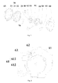
Fig. 1 is an exploded structure diagram of a coiling device according to an embodiment of the invention; -
Fig. 2 is a part section view of a locking state of a coiling device according to an embodiment of the invention; -
Fig. 3 is a part section view of an unlocking state of a coiling device according to an embodiment of the invention; -
Fig. 4 is an assembly structure diagram of a coiling device according to an embodiment of the invention; and -
Fig. 5 is a part section view of a dehumidifier according to an embodiment of the invention. - Drawing marks: 10, first coiling bobbin; 11, first limiting portion; 20, second coiling bobbin; 30, storage assembly; 31, accommodating cavity; 32, storage housing; 33, guide rail; 40, transmission gear; 50, drive assembly; 60, housing; 61, limiting block; 611, handle portion; 612, limiting end portion; 62, spring; 63, rotary shaft; 64, mounting box; 65, mounting cover; 70, connecting shaft; 91, first segment; 92, second segment; and 93, third segment.
- It is important to note that the embodiments of the invention and the characteristics in the embodiments can be combined under the condition of no conflicts. The invention is described below with reference to the drawings and the embodiments in detail.
- As shown in
Fig. 1 to Fig. 4 , an embodiment of the invention provides a coiling device, which is configured to coil a power cord. The power cord comprises afirst segment 91, asecond segment 92 and athird segment 93, connected with each other. The coiling device comprises ahousing 60, afirst coiling bobbin 10 and asecond coiling bobbin 20, wherein thefirst coiling bobbin 10 and thesecond coiling bobbin 20 are provided inside thehousing 60 rotatably. The first coilingbobbin 10 is provided with a first coiling groove, thefirst segment 91 of the power cord is wound in the first coiling groove, and one end, serving as a free end, of the first segment extends out of thehousing 60. The secondcoiling bobbin 20 is fixedly connected with thefirst coiling bobbin 10, and thesecond coiling bobbin 20 is provided with a second coiling groove, thesecond segment 92 of the power cord is wound in the second coiling groove, and a winding direction of thesecond segment 92 of the power cord is identical to a winding direction of thefirst segment 91 of the power cord. Thethird segment 93 of the power cord is connected with thesecond segment 92 of the power cord, extends out of thehousing 60, and is used as a connecting end of the power cord. - The first
coiling bobbin 10 and the secondcoiling bobbin 20 are provided, and the winding direction of thefirst segment 91 of the power cord and the winding direction of thesecond segment 92 of the power cord are set to be identical. When thefirst segment 91 of the power cord is pulled out of the first coiling groove, the firstcoiling bobbin 10 drives the secondcoiling bobbin 20 to rotate, and thesecond segment 92 of the power cord is unwound from the second coiling groove accordingly, so that the power cord is prevented from being twisted at a point of connection between thefirst segment 91 of the power cord and thesecond segment 92 of the power cord, and therefore the aim of improving use safety can be achieved without an elastic piece and an contact structure. - As shown in
Fig. 1 , thefirst coiling bobbin 10 and thesecond coiling bobbin 20 in the embodiment of the invention are fixedly connected by a screw, the circles of thefirst coiling bobbin 10 and thesecond coiling bobbin 20 and the axis of the connectingshaft 70 are located on a straight line, and thefirst coiling bobbin 10 and the secondcoiling bobbin 20 rotate around the connectingshaft 70. - Specifically, a mounting hole is provided at the
first coiling bobbin 10. Correspondingly, a mounting column in fit connection with the mounting hole is provided at a side surface, opposite to the first coilingbobbin 10, of the secondcoiling bobbin 20. The screw penetrates through the mounting hole and extends to the mounting column, so as to allow the second coilingbobbin 20 to be fixed to the first coilingbobbin 10. - Preferably, a first cord outlet hole is provided at the
first coiling bobbin 10, a second cord outlet hole opposite to the first cord outlet hole is provided at thesecond coiling bobbin 20, a non-free end of thefirst segment 91 of the power cord penetrates out of the first cord outlet hole, and one end of thesecond segment 92 of the power cord penetrates out of the second cord outlet hole and is integrally connected with the non-free end of thefirst segment 91 of the power cord, which penetrates out of the first cord outlet hole. - The coiling device in the embodiment of the invention further comprises a
storage assembly 30 fitting with thesecond coiling bobbin 20, thestorage assembly 30 is provided with anaccommodating cavity 31, and when the free end of thefirst segment 91 of the power cord is pulled out of thefirst coiling bobbin 10, thefirst coiling bobbin 10 drives thesecond coiling bobbin 20 to rotate, and thesecond segment 92 of the power cord performs unwinding operation at the same time. Namely, thesecond segment 92 of the power cord is unwound from the second coiling groove and enters theaccommodating cavity 31 to be stored. - By providing the
storage assembly 30, when thesecond segment 92 of the power cord is unwound from the second coiling groove, thesecond segment 92 of the power cord, provided outside the second coiling groove, can be accommodated inside theaccommodating cavity 31 by means of thestorage assembly 30, so as to avoid the problem that thesecond segment 92 of the power cord is wound inside the coiling device. - As shown in
Fig. 1 , thestorage assembly 30 comprises astorage housing 32 and aguide rail 33 provided in thestorage housing 32, and theaccommodating cavity 31 is cooperatively formed by theguide rail 33 and thestorage housing 32. Preferably, thesecond coiling bobbin 20 is of an outer gear structure, thestorage assembly 30 is of an inner gear structure, the coiling device further comprises atransmission gear 40, and thetransmission gear 40 meshes with thesecond coiling bobbin 20 and thestorage assembly 30 respectively. In a clockwise rotation process of thefirst coiling bobbin 10 and thesecond coiling bobbin 20 as shown inFig. 1 , thesecond segment 92 of the power cord is unwound from the second coiling groove, and thestorage assembly 30 rotates anticlockwise under an action of thetransmission gear 40 to make a movement direction of theguide rail 33 opposite to that of thesecond coiling bobbin 20. When being unwound from the secondcoiling bobbin 20, thesecond segment 92 of the power cord enters theaccommodating cavity 31 under the action of theguide rail 33 to be stored. - The
guide rail 33 in the embodiment of the invention is an annular guide rail adapting to an inner cavity structure of thestorage housing 32, an opening is provided on the annular guide rail, and thethird segment 93 of the power cord penetrates from the opening to the exterior of thehousing 60. When the coiling device works, thethird segment 93 of the power cord remains stationary, and thefirst segment 91 of the power cord is manually pulled out, so that thesecond segment 92 of the power cord is unwound from the second coiling groove, a rotation direction of thestorage assembly 30 is opposite to a rotation direction of thesecond coiling bobbin 20, and thesecond segment 92 of the power cord can enter theaccommodating cavity 31 from the opening under the action of theguide rail 33. When thefirst segment 91 of the power cord is wound, the movement direction of the structure is opposite, and will not be repeated here. - In order to enable the coiling device to realize automatic coiling, the coiling device in the embodiment of the invention further comprises a
drive assembly 50 connected with thefirst coiling bobbin 10 drivably. - Specifically, as shown in
Fig. 1 , the housing in the embodiment of the invention is provided with amounting box 64 having a cavity and amounting cover 65 connected with themounting box 64 detachably, thefirst coiling bobbin 10 is provided in the cavity of themounting box 64 rotatably, and thedrive assembly 50 is a coil spring mounted at themounting box 64 and connected with thefirst coiling bobbin 10. - Preferably, the coil spring is provided with a middle fixed end and a free end, the middle fixed end of the coil spring is connected with the
mounting box 64 fixedly, and the free end of the coil spring is fixed with the firstcoiling bobbin 10 and rotates along with the firstcoiling bobbin 10. When the first coilingbobbin 10 rotates clockwise, namely when thefirst segment 91 of the power cord is pulled out, the coil spring is contracted and tightly coiled to store mechanical energy for spring-back. Otherwise, the mechanical energy in the coil spring is released, and the coil spring shows a tendency to restore an initial position, so as to drive thefirst coiling bobbin 10 to rotate anticlockwise, and thefirst segment 91 of the power cord is re-wound into the first coiling groove. - Preferably, a first limiting
portion 11 is provided on thefirst coiling bobbin 10, the coiling device further comprises a second limiting portion fitting with the first limitingportion 11 to limit a rotation angle of thefirst coiling bobbin 10. The rotation angle of thefirst coiling bobbin 10 can be limited by means of the first limitingportion 11 and the second limiting portion, so that the pull-out length of thefirst segment 91 of the power cord can remain unchanged in a non-unlocking state. - The first limiting
portion 11 in the embodiment of the invention is a ratchet provided at the periphery of thefirst coiling bobbin 10, and the second limiting portion is a limitingblock 61 provided on the mountingbox 64. Specifically, each ratchet has a sliding surface in sliding fit with the second limiting portion in a non-limiting direction (referring to a clockwise direction in the embodiment, namely a pull-out direction of the first segment of the power cord) and a clamping surface clamped with the second limiting portion in a limiting direction. - As shown in
Fig. 2 andFig. 3 , arotary shaft 63 is provided at the mountingbox 64, the limitingblock 61 is provided on therotary shaft 63 rotatably, and the limitingblock 61 comprises ahandle portion 611 arranged outside the mountingbox 64 and a limitingend portion 612 arranged inside the mountingbox 64, the limitingend portion 612 being in clamping fit with the ratchet. When it is necessary to lock thefirst coiling bobbin 10, thehandle portion 611 is lifted to allow the limitingend portion 612 to be pressed down so as to be clamped with the ratchet, thereby limiting the rotation of thefirst coiling bobbin 10. When it is necessary to unlock thefirst coiling bobbin 10, thehandle portion 611 is pressed down to allow the limitingend portion 612 to be lifted, thereby unclamping the limitingend portion 612 from the ratchet. - Preferably, the second limiting portion further comprises a
spring 62, a mounting slot is provided at the mountingbox 64, and thespring 62 is provided in the mounting slot and is in extrusion fit with the limitingend portion 612 so as to allow the limitingend portion 612 to be clamped with the ratchets under a normal state. The clamping of the limitingend portion 612 and the ratchet can be remained by means of thespring 62, so as to ensure that thefirst segment 91 of the power cord can be pulled out for a random length without withdrawal under the driving of the coil spring, thereby avoiding the problem of breakage caused by long-time exertion of a recovery pull force on the power cord in a using process. - An embodiment of the invention also provides a household appliance, which comprises an appliance housing, a power cord and an above-mentioned coiling device. A fixing portion is provided at a housing of the coiling device, a screw penetrates through the fixing portion to entirely fix the coiling device to a set mounting position inside the appliance housing, and a
first segment 91 of the power cord is used as a plug connecting end of the household appliance, namely the plug connecting end can be freely pulled out. Asecond segment 92 of the power cord, serving as a middle transition segment, is provided in the coiling device, and athird segment 93 of the power cord is connected with thesecond segment 92 of the power cord, extends out of the coiling device and is connected with a corresponding connecting end of the household appliance so as to supply power to the household appliance. - It is important to note that the household appliance comprises a dehumidifier, a humidifier, a dust collector and the like. All household appliances having the coiling devices shall fall within the protection scope of the invention.
- As shown in
Fig. 5 , the household appliance is the dehumidifier, a housing of the dehumidifier is provided with an outlet of afirst segment 91 of a power cord, the coiling device is fixed to the interior of the housing of the dehumidifier, and a mounting portion matched with an internal support of the dehumidifier fixedly is provided at a mountingbox 64. - From the above descriptions, it can be seen that the embodiments of the invention achieve the technical effects as follows. The first coiling bobbin and the second coiling bobbin are provided, and the winding directions of the first segment and the second segment of the power cord are set to be identical. When the first segment of the power cord is pulled out of the first coiling groove, the first coiling bobbin drives the second coiling bobbin to rotate, and the second segment of the power cord is unwound from the second coiling groove accordingly, so that the power cord is prevented from being twisted at the point of connection between the first segment and the second segment, and therefore the aim of improving the use safety can be achieved without the elastic piece and contact structure.
- The above is only the preferred embodiments of the invention, and is not intended to limit the invention. There can be various modifications and variations in the invention for those skilled in the art. Any modifications, equivalent replacements, improvements and the like within the spirit and principle of the invention shall fall within the protection scope of the invention.
Claims (12)
- A coiling device, configured to coil a power cord, the power cord comprising a first segment (91) and a second segment (92) connected with each other, wherein the coiling device comprises:a first coiling bobbin (10), provided with a first coiling groove, the first segment (91) of the power cord being wound in the first coiling groove; anda second coiling bobbin (20), fixedly connected with the first coiling bobbin (10), the second coiling bobbin (20) being provided with a second coiling groove, the second segment (92) of the power cord being wound in the second coiling groove, and a winding direction of the second segment (92) of the power cord being identical to that of the first segment (91) of the power cord.
- The coiling device according to claim 1, further comprising a storage assembly (30), wherein the storage assembly (30) is provided with an accommodating cavity (31), and when the first segment (91) of the power cord is pulled out of the first coiling bobbin (10), the second segment (92) of the power cord enters the accommodating cavity (31) from the second coiling groove.
- The coiling device according to claim 2, wherein the storage assembly (30) comprises a storage housing (32) and a guide rail (33) arranged in the storage housing (32), and the accommodating cavity (31) is cooperatively formed by the guide rail (33) and the storage housing (32).
- The coiling device according to claim 2, wherein the second coiling bobbin (20) is of an outer gear structure, the storage assembly (30) is of an inner gear structure, the coiling device further comprises a transmission gear (40), and the transmission gear (40) meshes with the second coiling bobbin (20) and the storage assembly (30) respectively.
- The coiling device according to claim 1, further comprising a drive assembly (50) in drive connection with the first coiling bobbin (10).
- The coiling device according to claim 5, further comprising a housing (60), wherein the first coiling bobbin (10) is provided on the housing (60) rotatably, and the drive assembly (50) is a coil spring mounted on the housing (60) and connected with the first coiling bobbin (10).
- The coiling device according to claim 1, wherein a first limiting portion (11) is provided on the first coiling bobbin (10), and the coiling device further comprises a second limiting portion fitting with the first limiting portions (11) to limit a rotation angle of the first coiling bobbin (10).
- The coiling device according to claim 7, further comprising a housing (60), wherein the first coiling bobbin (10) is provided on the housing (60) rotatably, the first limiting portion (11) is a ratchet provided at the periphery of the first coiling bobbin (10), and the second limiting portion is a limiting block (61) provided on the housing (60).
- The coiling device according to claim 8, wherein a rotary shaft (63) is provided on the housing (60), the limiting block (61) is provided on the rotary shaft (63) rotatably, and the limiting block (61) comprises a handle portion (611) arranged outside the housing (60) and a limiting end portion (612) arranged inside the housing (60), the limiting end portion is matched with the ratchet in a clamping manner.
- The coiling device according to claim 9, wherein the second limiting portion further comprises a spring (62) which is provided at the housing (60) and is matched with the limiting end portion (612) in a squeezing manner so as to allow the limiting end portion (612) to be clamped with the ratchet under a normal state.
- A household appliance, comprising a power cord and a coiling device, wherein the coiling device is a coiling device according to any one of claims 1 to 10.
- The household appliance according to claim 11, comprising an appliance housing, the coiling device being detachably fixed to an interior of the appliance housing by screws.
Applications Claiming Priority (2)
| Application Number | Priority Date | Filing Date | Title |
|---|---|---|---|
| CN201310719359.XA CN104733947B (en) | 2013-12-23 | 2013-12-23 | Winding device and household appliance with same |
| PCT/CN2014/088146 WO2015096531A1 (en) | 2013-12-23 | 2014-10-08 | Coiling device and household appliance with same |
Publications (3)
| Publication Number | Publication Date |
|---|---|
| EP3089283A1 true EP3089283A1 (en) | 2016-11-02 |
| EP3089283A4 EP3089283A4 (en) | 2017-07-05 |
| EP3089283B1 EP3089283B1 (en) | 2020-12-02 |
Family
ID=53457563
Family Applications (1)
| Application Number | Title | Priority Date | Filing Date |
|---|---|---|---|
| EP14873171.4A Active EP3089283B1 (en) | 2013-12-23 | 2014-10-08 | Coiling device and household appliance having the same |
Country Status (5)
| Country | Link |
|---|---|
| US (1) | US9960546B2 (en) |
| EP (1) | EP3089283B1 (en) |
| CN (1) | CN104733947B (en) |
| ES (1) | ES2844575T3 (en) |
| WO (1) | WO2015096531A1 (en) |
Families Citing this family (14)
| Publication number | Priority date | Publication date | Assignee | Title |
|---|---|---|---|---|
| CN104097994A (en) * | 2014-07-22 | 2014-10-15 | 珠海格力电器股份有限公司 | Winder and electrical equipment with same |
| CN105281144B (en) * | 2015-11-18 | 2017-12-12 | 常州红芦电子有限公司 | Portable patchcord |
| CN105281145B (en) * | 2015-11-18 | 2017-07-07 | 常州红芦电子有限公司 | Novel portable patchcord |
| CN105680260B (en) * | 2016-03-16 | 2019-08-02 | 青岛歌尔声学科技有限公司 | A kind of spiral mould group |
| CN106953388A (en) * | 2017-04-28 | 2017-07-14 | 中山市壹辉财税服务有限公司 | A car charger with retractable socket |
| CN108233118A (en) * | 2017-07-28 | 2018-06-29 | 广州腾耐计算机科技有限公司 | A kind of length-adjustable socket device |
| CN108232787A (en) * | 2017-07-28 | 2018-06-29 | 广州腾耐计算机科技有限公司 | A kind of socket device of modified power supply |
| CN107720452B (en) * | 2017-09-14 | 2024-05-28 | 东莞市趣电智能科技有限公司 | Positioning device |
| CN107651515A (en) * | 2017-09-14 | 2018-02-02 | 东莞市趣电智能科技有限公司 | An automatic winding mechanism |
| CN108599056A (en) * | 2018-07-02 | 2018-09-28 | 云南电网有限责任公司保山供电局 | A kind of ground wire aggregating apparatus for electric operation |
| CN109140284A (en) * | 2018-09-29 | 2019-01-04 | 卢子璇 | A kind of intelligent power saving desk lamp |
| CN109204044B (en) * | 2018-11-05 | 2020-12-18 | 柏树林汽车设计(重庆)有限公司 | Anticreep has electric pile that fills of wheel function of washing for new energy automobile |
| CN113509085A (en) * | 2020-06-09 | 2021-10-19 | 苏州市春菊电器有限公司 | Tight wheel carrier fixed knot that reliability is high constructs |
| CN117440262B (en) * | 2023-12-19 | 2024-03-19 | 深圳拓普龙科技有限公司 | Distribution frame for communication cabinet |
Family Cites Families (19)
| Publication number | Priority date | Publication date | Assignee | Title |
|---|---|---|---|---|
| GB1424018A (en) * | 1972-07-01 | 1976-02-04 | Greene Gmbh & Co Kg Maschbau | Winding machines |
| US5701981A (en) * | 1996-03-13 | 1997-12-30 | Marshall; Trevor | Retractable power cord |
| US6077108A (en) | 1997-12-31 | 2000-06-20 | Krone Gmbh | Patch panel with retractable patch cord |
| US7176411B2 (en) * | 2004-03-15 | 2007-02-13 | Lincoln Global, Inc. | Wire feeder |
| JP4326519B2 (en) * | 2005-03-31 | 2009-09-09 | 日東電工株式会社 | Protective tape peeling method and apparatus using the same |
| US7599598B2 (en) | 2006-08-09 | 2009-10-06 | Adc Telecommunications, Inc. | Cable payout systems and methods |
| US20080203075A1 (en) * | 2007-02-27 | 2008-08-28 | Feldhausen Joseph E | Portable structural welding system having integrated resources |
| EP2118669B1 (en) * | 2007-03-09 | 2013-01-30 | Nexus Biosystems, Inc., | Device and method for removing a peelable seal |
| CN201118006Y (en) * | 2007-10-10 | 2008-09-17 | 宁波云环电子集团有限公司 | Collapsible automatic winding roll |
| CN201174475Y (en) * | 2008-02-29 | 2008-12-31 | 松下·万宝(广州)电熨斗有限公司 | Power wire coiler |
| US8878097B2 (en) * | 2008-08-18 | 2014-11-04 | Lincoln Global, Inc. | Wire feeder with curved force generating element(s) for better positioning of an adjusting mechanism |
| GB2469302B (en) * | 2009-04-08 | 2011-07-13 | Arthur Leslie Tomlinson | Cable winding device |
| CN201515115U (en) * | 2009-09-14 | 2010-06-23 | 郑鸿文 | Single-pull composite winding mandrel |
| US20120077372A1 (en) | 2010-09-24 | 2012-03-29 | John Mezzalingua Associates, Inc. | Cable jumper hand reel |
| US8720810B2 (en) * | 2011-02-11 | 2014-05-13 | Adc Telecommunications, Inc. | Spool for telecommunications cable and method |
| US9187291B2 (en) * | 2012-05-18 | 2015-11-17 | Clark J. Alexandre | Cord organizer for portable electronic devices |
| US9527153B2 (en) * | 2013-03-14 | 2016-12-27 | Lincoln Global, Inc. | Camera and wire feed solution for orbital welder system |
| US9517524B2 (en) * | 2013-11-12 | 2016-12-13 | Lincoln Global, Inc. | Welding wire spool support |
| CN203631911U (en) * | 2013-12-23 | 2014-06-04 | 珠海格力电器股份有限公司 | Winding device and household appliance with same |
-
2013
- 2013-12-23 CN CN201310719359.XA patent/CN104733947B/en active Active
-
2014
- 2014-10-08 EP EP14873171.4A patent/EP3089283B1/en active Active
- 2014-10-08 US US15/107,057 patent/US9960546B2/en active Active
- 2014-10-08 ES ES14873171T patent/ES2844575T3/en active Active
- 2014-10-08 WO PCT/CN2014/088146 patent/WO2015096531A1/en not_active Ceased
Also Published As
| Publication number | Publication date |
|---|---|
| CN104733947B (en) | 2017-02-15 |
| US9960546B2 (en) | 2018-05-01 |
| EP3089283A4 (en) | 2017-07-05 |
| CN104733947A (en) | 2015-06-24 |
| US20170033516A1 (en) | 2017-02-02 |
| EP3089283B1 (en) | 2020-12-02 |
| WO2015096531A1 (en) | 2015-07-02 |
| ES2844575T3 (en) | 2021-07-22 |
Similar Documents
| Publication | Publication Date | Title |
|---|---|---|
| US9960546B2 (en) | Coiling device and household appliance having the same | |
| US9567186B2 (en) | Motorized hose reel with anti-rotation interlock | |
| CN105035883B (en) | Cable drum and crane | |
| CN102544937A (en) | Automatic retraction type wire coil | |
| KR101371672B1 (en) | Earphone line auto winding device | |
| US3322372A (en) | Cable winding device | |
| CN201528100U (en) | Device for automatically winding power line | |
| WO2007102649A1 (en) | Cord reel assembly and vacuum cleaner having the same | |
| CN101420112B (en) | Automatic wire coiling and packing device | |
| CN110902503A (en) | Electric power cabinet body with receive and release line function | |
| CN203631911U (en) | Winding device and household appliance with same | |
| CN209774603U (en) | Storage device for power maintenance tools | |
| CN208112865U (en) | A kind of wire winding headphone | |
| CN108184186B (en) | Winding earphone | |
| CN203998456U (en) | Winder and electrical equipment with same | |
| CN106384923B (en) | Cable receiving mechanism and electric cooker | |
| CN205892374U (en) | Electric wire admission extinguisher | |
| CN209497071U (en) | A kind of DC power supply socket with function of receiving line | |
| KR200294024Y1 (en) | cord reel concent | |
| CN210120288U (en) | Automatic take-up power panel | |
| CN219823297U (en) | Wire winding mechanism and household appliance | |
| CN207536945U (en) | A kind of winder | |
| KR101753599B1 (en) | Electric wire winding apparatus | |
| CN104097994A (en) | Winder and electrical equipment with same | |
| CN220766188U (en) | Lock non-return roll control structure of winding roll |
Legal Events
| Date | Code | Title | Description |
|---|---|---|---|
| PUAI | Public reference made under article 153(3) epc to a published international application that has entered the european phase |
Free format text: ORIGINAL CODE: 0009012 |
|
| 17P | Request for examination filed |
Effective date: 20160624 |
|
| AK | Designated contracting states |
Kind code of ref document: A1 Designated state(s): AL AT BE BG CH CY CZ DE DK EE ES FI FR GB GR HR HU IE IS IT LI LT LU LV MC MK MT NL NO PL PT RO RS SE SI SK SM TR |
|
| AX | Request for extension of the european patent |
Extension state: BA ME |
|
| DAX | Request for extension of the european patent (deleted) | ||
| A4 | Supplementary search report drawn up and despatched |
Effective date: 20170601 |
|
| RIC1 | Information provided on ipc code assigned before grant |
Ipc: H01R 24/30 20110101ALN20170526BHEP Ipc: H01R 13/72 20060101AFI20170526BHEP |
|
| STAA | Information on the status of an ep patent application or granted ep patent |
Free format text: STATUS: EXAMINATION IS IN PROGRESS |
|
| 17Q | First examination report despatched |
Effective date: 20190412 |
|
| RIC1 | Information provided on ipc code assigned before grant |
Ipc: H01R 24/30 20110101ALN20200716BHEP Ipc: H01R 13/72 20060101AFI20200716BHEP |
|
| RIC1 | Information provided on ipc code assigned before grant |
Ipc: H01R 13/72 20060101AFI20200724BHEP Ipc: H02G 11/02 20060101ALI20200724BHEP Ipc: H01R 24/30 20110101ALN20200724BHEP |
|
| GRAP | Despatch of communication of intention to grant a patent |
Free format text: ORIGINAL CODE: EPIDOSNIGR1 |
|
| STAA | Information on the status of an ep patent application or granted ep patent |
Free format text: STATUS: GRANT OF PATENT IS INTENDED |
|
| INTG | Intention to grant announced |
Effective date: 20200911 |
|
| GRAS | Grant fee paid |
Free format text: ORIGINAL CODE: EPIDOSNIGR3 |
|
| GRAA | (expected) grant |
Free format text: ORIGINAL CODE: 0009210 |
|
| STAA | Information on the status of an ep patent application or granted ep patent |
Free format text: STATUS: THE PATENT HAS BEEN GRANTED |
|
| AK | Designated contracting states |
Kind code of ref document: B1 Designated state(s): AL AT BE BG CH CY CZ DE DK EE ES FI FR GB GR HR HU IE IS IT LI LT LU LV MC MK MT NL NO PL PT RO RS SE SI SK SM TR |
|
| REG | Reference to a national code |
Ref country code: GB Ref legal event code: FG4D |
|
| REG | Reference to a national code |
Ref country code: AT Ref legal event code: REF Ref document number: 1341952 Country of ref document: AT Kind code of ref document: T Effective date: 20201215 Ref country code: CH Ref legal event code: EP |
|
| REG | Reference to a national code |
Ref country code: IE Ref legal event code: FG4D |
|
| REG | Reference to a national code |
Ref country code: DE Ref legal event code: R096 Ref document number: 602014073064 Country of ref document: DE |
|
| PG25 | Lapsed in a contracting state [announced via postgrant information from national office to epo] |
Ref country code: GR Free format text: LAPSE BECAUSE OF FAILURE TO SUBMIT A TRANSLATION OF THE DESCRIPTION OR TO PAY THE FEE WITHIN THE PRESCRIBED TIME-LIMIT Effective date: 20210303 Ref country code: FI Free format text: LAPSE BECAUSE OF FAILURE TO SUBMIT A TRANSLATION OF THE DESCRIPTION OR TO PAY THE FEE WITHIN THE PRESCRIBED TIME-LIMIT Effective date: 20201202 Ref country code: RS Free format text: LAPSE BECAUSE OF FAILURE TO SUBMIT A TRANSLATION OF THE DESCRIPTION OR TO PAY THE FEE WITHIN THE PRESCRIBED TIME-LIMIT Effective date: 20201202 Ref country code: NO Free format text: LAPSE BECAUSE OF FAILURE TO SUBMIT A TRANSLATION OF THE DESCRIPTION OR TO PAY THE FEE WITHIN THE PRESCRIBED TIME-LIMIT Effective date: 20210302 |
|
| REG | Reference to a national code |
Ref country code: NL Ref legal event code: MP Effective date: 20201202 |
|
| REG | Reference to a national code |
Ref country code: AT Ref legal event code: MK05 Ref document number: 1341952 Country of ref document: AT Kind code of ref document: T Effective date: 20201202 |
|
| PG25 | Lapsed in a contracting state [announced via postgrant information from national office to epo] |
Ref country code: SE Free format text: LAPSE BECAUSE OF FAILURE TO SUBMIT A TRANSLATION OF THE DESCRIPTION OR TO PAY THE FEE WITHIN THE PRESCRIBED TIME-LIMIT Effective date: 20201202 Ref country code: PL Free format text: LAPSE BECAUSE OF FAILURE TO SUBMIT A TRANSLATION OF THE DESCRIPTION OR TO PAY THE FEE WITHIN THE PRESCRIBED TIME-LIMIT Effective date: 20201202 Ref country code: LV Free format text: LAPSE BECAUSE OF FAILURE TO SUBMIT A TRANSLATION OF THE DESCRIPTION OR TO PAY THE FEE WITHIN THE PRESCRIBED TIME-LIMIT Effective date: 20201202 Ref country code: BG Free format text: LAPSE BECAUSE OF FAILURE TO SUBMIT A TRANSLATION OF THE DESCRIPTION OR TO PAY THE FEE WITHIN THE PRESCRIBED TIME-LIMIT Effective date: 20210302 |
|
| PG25 | Lapsed in a contracting state [announced via postgrant information from national office to epo] |
Ref country code: HR Free format text: LAPSE BECAUSE OF FAILURE TO SUBMIT A TRANSLATION OF THE DESCRIPTION OR TO PAY THE FEE WITHIN THE PRESCRIBED TIME-LIMIT Effective date: 20201202 Ref country code: NL Free format text: LAPSE BECAUSE OF FAILURE TO SUBMIT A TRANSLATION OF THE DESCRIPTION OR TO PAY THE FEE WITHIN THE PRESCRIBED TIME-LIMIT Effective date: 20201202 |
|
| REG | Reference to a national code |
Ref country code: LT Ref legal event code: MG9D |
|
| REG | Reference to a national code |
Ref country code: ES Ref legal event code: FG2A Ref document number: 2844575 Country of ref document: ES Kind code of ref document: T3 Effective date: 20210722 |
|
| PG25 | Lapsed in a contracting state [announced via postgrant information from national office to epo] |
Ref country code: SK Free format text: LAPSE BECAUSE OF FAILURE TO SUBMIT A TRANSLATION OF THE DESCRIPTION OR TO PAY THE FEE WITHIN THE PRESCRIBED TIME-LIMIT Effective date: 20201202 Ref country code: RO Free format text: LAPSE BECAUSE OF FAILURE TO SUBMIT A TRANSLATION OF THE DESCRIPTION OR TO PAY THE FEE WITHIN THE PRESCRIBED TIME-LIMIT Effective date: 20201202 Ref country code: PT Free format text: LAPSE BECAUSE OF FAILURE TO SUBMIT A TRANSLATION OF THE DESCRIPTION OR TO PAY THE FEE WITHIN THE PRESCRIBED TIME-LIMIT Effective date: 20210405 Ref country code: LT Free format text: LAPSE BECAUSE OF FAILURE TO SUBMIT A TRANSLATION OF THE DESCRIPTION OR TO PAY THE FEE WITHIN THE PRESCRIBED TIME-LIMIT Effective date: 20201202 Ref country code: SM Free format text: LAPSE BECAUSE OF FAILURE TO SUBMIT A TRANSLATION OF THE DESCRIPTION OR TO PAY THE FEE WITHIN THE PRESCRIBED TIME-LIMIT Effective date: 20201202 Ref country code: EE Free format text: LAPSE BECAUSE OF FAILURE TO SUBMIT A TRANSLATION OF THE DESCRIPTION OR TO PAY THE FEE WITHIN THE PRESCRIBED TIME-LIMIT Effective date: 20201202 Ref country code: CZ Free format text: LAPSE BECAUSE OF FAILURE TO SUBMIT A TRANSLATION OF THE DESCRIPTION OR TO PAY THE FEE WITHIN THE PRESCRIBED TIME-LIMIT Effective date: 20201202 |
|
| PG25 | Lapsed in a contracting state [announced via postgrant information from national office to epo] |
Ref country code: AT Free format text: LAPSE BECAUSE OF FAILURE TO SUBMIT A TRANSLATION OF THE DESCRIPTION OR TO PAY THE FEE WITHIN THE PRESCRIBED TIME-LIMIT Effective date: 20201202 |
|
| REG | Reference to a national code |
Ref country code: DE Ref legal event code: R097 Ref document number: 602014073064 Country of ref document: DE |
|
| PG25 | Lapsed in a contracting state [announced via postgrant information from national office to epo] |
Ref country code: IS Free format text: LAPSE BECAUSE OF FAILURE TO SUBMIT A TRANSLATION OF THE DESCRIPTION OR TO PAY THE FEE WITHIN THE PRESCRIBED TIME-LIMIT Effective date: 20210402 |
|
| PLBE | No opposition filed within time limit |
Free format text: ORIGINAL CODE: 0009261 |
|
| STAA | Information on the status of an ep patent application or granted ep patent |
Free format text: STATUS: NO OPPOSITION FILED WITHIN TIME LIMIT |
|
| PG25 | Lapsed in a contracting state [announced via postgrant information from national office to epo] |
Ref country code: AL Free format text: LAPSE BECAUSE OF FAILURE TO SUBMIT A TRANSLATION OF THE DESCRIPTION OR TO PAY THE FEE WITHIN THE PRESCRIBED TIME-LIMIT Effective date: 20201202 |
|
| 26N | No opposition filed |
Effective date: 20210903 |
|
| PG25 | Lapsed in a contracting state [announced via postgrant information from national office to epo] |
Ref country code: DK Free format text: LAPSE BECAUSE OF FAILURE TO SUBMIT A TRANSLATION OF THE DESCRIPTION OR TO PAY THE FEE WITHIN THE PRESCRIBED TIME-LIMIT Effective date: 20201202 Ref country code: SI Free format text: LAPSE BECAUSE OF FAILURE TO SUBMIT A TRANSLATION OF THE DESCRIPTION OR TO PAY THE FEE WITHIN THE PRESCRIBED TIME-LIMIT Effective date: 20201202 |
|
| REG | Reference to a national code |
Ref country code: CH Ref legal event code: PL |
|
| PG25 | Lapsed in a contracting state [announced via postgrant information from national office to epo] |
Ref country code: IS Free format text: LAPSE BECAUSE OF FAILURE TO SUBMIT A TRANSLATION OF THE DESCRIPTION OR TO PAY THE FEE WITHIN THE PRESCRIBED TIME-LIMIT Effective date: 20210402 |
|
| REG | Reference to a national code |
Ref country code: BE Ref legal event code: MM Effective date: 20211031 |
|
| GBPC | Gb: european patent ceased through non-payment of renewal fee |
Effective date: 20211008 |
|
| PG25 | Lapsed in a contracting state [announced via postgrant information from national office to epo] |
Ref country code: MC Free format text: LAPSE BECAUSE OF FAILURE TO SUBMIT A TRANSLATION OF THE DESCRIPTION OR TO PAY THE FEE WITHIN THE PRESCRIBED TIME-LIMIT Effective date: 20201202 |
|
| PG25 | Lapsed in a contracting state [announced via postgrant information from national office to epo] |
Ref country code: LU Free format text: LAPSE BECAUSE OF NON-PAYMENT OF DUE FEES Effective date: 20211008 Ref country code: GB Free format text: LAPSE BECAUSE OF NON-PAYMENT OF DUE FEES Effective date: 20211008 Ref country code: BE Free format text: LAPSE BECAUSE OF NON-PAYMENT OF DUE FEES Effective date: 20211031 |
|
| PG25 | Lapsed in a contracting state [announced via postgrant information from national office to epo] |
Ref country code: LI Free format text: LAPSE BECAUSE OF NON-PAYMENT OF DUE FEES Effective date: 20211031 Ref country code: CH Free format text: LAPSE BECAUSE OF NON-PAYMENT OF DUE FEES Effective date: 20211031 |
|
| PG25 | Lapsed in a contracting state [announced via postgrant information from national office to epo] |
Ref country code: FR Free format text: LAPSE BECAUSE OF NON-PAYMENT OF DUE FEES Effective date: 20211031 |
|
| PG25 | Lapsed in a contracting state [announced via postgrant information from national office to epo] |
Ref country code: IE Free format text: LAPSE BECAUSE OF NON-PAYMENT OF DUE FEES Effective date: 20211008 |
|
| PG25 | Lapsed in a contracting state [announced via postgrant information from national office to epo] |
Ref country code: HU Free format text: LAPSE BECAUSE OF FAILURE TO SUBMIT A TRANSLATION OF THE DESCRIPTION OR TO PAY THE FEE WITHIN THE PRESCRIBED TIME-LIMIT; INVALID AB INITIO Effective date: 20141008 |
|
| PG25 | Lapsed in a contracting state [announced via postgrant information from national office to epo] |
Ref country code: CY Free format text: LAPSE BECAUSE OF FAILURE TO SUBMIT A TRANSLATION OF THE DESCRIPTION OR TO PAY THE FEE WITHIN THE PRESCRIBED TIME-LIMIT Effective date: 20201202 |
|
| P01 | Opt-out of the competence of the unified patent court (upc) registered |
Effective date: 20230530 |
|
| PG25 | Lapsed in a contracting state [announced via postgrant information from national office to epo] |
Ref country code: MK Free format text: LAPSE BECAUSE OF FAILURE TO SUBMIT A TRANSLATION OF THE DESCRIPTION OR TO PAY THE FEE WITHIN THE PRESCRIBED TIME-LIMIT Effective date: 20201202 |
|
| PG25 | Lapsed in a contracting state [announced via postgrant information from national office to epo] |
Ref country code: MT Free format text: LAPSE BECAUSE OF FAILURE TO SUBMIT A TRANSLATION OF THE DESCRIPTION OR TO PAY THE FEE WITHIN THE PRESCRIBED TIME-LIMIT Effective date: 20201202 |
|
| PG25 | Lapsed in a contracting state [announced via postgrant information from national office to epo] |
Ref country code: TR Free format text: LAPSE BECAUSE OF FAILURE TO SUBMIT A TRANSLATION OF THE DESCRIPTION OR TO PAY THE FEE WITHIN THE PRESCRIBED TIME-LIMIT Effective date: 20201202 |
|
| PGFP | Annual fee paid to national office [announced via postgrant information from national office to epo] |
Ref country code: DE Payment date: 20251020 Year of fee payment: 12 |
|
| PGFP | Annual fee paid to national office [announced via postgrant information from national office to epo] |
Ref country code: IT Payment date: 20251031 Year of fee payment: 12 |
|
| PGFP | Annual fee paid to national office [announced via postgrant information from national office to epo] |
Ref country code: ES Payment date: 20251114 Year of fee payment: 12 |