EP3088934A1 - Display equipment and display unit - Google Patents
Display equipment and display unit Download PDFInfo
- Publication number
- EP3088934A1 EP3088934A1 EP14873396.7A EP14873396A EP3088934A1 EP 3088934 A1 EP3088934 A1 EP 3088934A1 EP 14873396 A EP14873396 A EP 14873396A EP 3088934 A1 EP3088934 A1 EP 3088934A1
- Authority
- EP
- European Patent Office
- Prior art keywords
- display
- image
- display device
- reflection
- display unit
- Prior art date
- Legal status (The legal status is an assumption and is not a legal conclusion. Google has not performed a legal analysis and makes no representation as to the accuracy of the status listed.)
- Withdrawn
Links
Images


Classifications
-
- G—PHYSICS
- G02—OPTICS
- G02B—OPTICAL ELEMENTS, SYSTEMS OR APPARATUS
- G02B27/00—Optical systems or apparatus not provided for by any of the groups G02B1/00 - G02B26/00, G02B30/00
- G02B27/01—Head-up displays
- G02B27/0101—Head-up displays characterised by optical features
-
- B—PERFORMING OPERATIONS; TRANSPORTING
- B60—VEHICLES IN GENERAL
- B60K—ARRANGEMENT OR MOUNTING OF PROPULSION UNITS OR OF TRANSMISSIONS IN VEHICLES; ARRANGEMENT OR MOUNTING OF PLURAL DIVERSE PRIME-MOVERS IN VEHICLES; AUXILIARY DRIVES FOR VEHICLES; INSTRUMENTATION OR DASHBOARDS FOR VEHICLES; ARRANGEMENTS IN CONNECTION WITH COOLING, AIR INTAKE, GAS EXHAUST OR FUEL SUPPLY OF PROPULSION UNITS IN VEHICLES
- B60K35/00—Instruments specially adapted for vehicles; Arrangement of instruments in or on vehicles
- B60K35/20—Output arrangements, i.e. from vehicle to user, associated with vehicle functions or specially adapted therefor
- B60K35/21—Output arrangements, i.e. from vehicle to user, associated with vehicle functions or specially adapted therefor using visual output, e.g. blinking lights or matrix displays
- B60K35/22—Display screens
-
- G—PHYSICS
- G02—OPTICS
- G02B—OPTICAL ELEMENTS, SYSTEMS OR APPARATUS
- G02B27/00—Optical systems or apparatus not provided for by any of the groups G02B1/00 - G02B26/00, G02B30/00
- G02B27/01—Head-up displays
-
- G—PHYSICS
- G02—OPTICS
- G02B—OPTICAL ELEMENTS, SYSTEMS OR APPARATUS
- G02B27/00—Optical systems or apparatus not provided for by any of the groups G02B1/00 - G02B26/00, G02B30/00
- G02B27/01—Head-up displays
- G02B27/0149—Head-up displays characterised by mechanical features
-
- G—PHYSICS
- G02—OPTICS
- G02B—OPTICAL ELEMENTS, SYSTEMS OR APPARATUS
- G02B5/00—Optical elements other than lenses
- G02B5/08—Mirrors
- G02B5/10—Mirrors with curved faces
-
- G—PHYSICS
- G03—PHOTOGRAPHY; CINEMATOGRAPHY; ANALOGOUS TECHNIQUES USING WAVES OTHER THAN OPTICAL WAVES; ELECTROGRAPHY; HOLOGRAPHY
- G03B—APPARATUS OR ARRANGEMENTS FOR TAKING PHOTOGRAPHS OR FOR PROJECTING OR VIEWING THEM; APPARATUS OR ARRANGEMENTS EMPLOYING ANALOGOUS TECHNIQUES USING WAVES OTHER THAN OPTICAL WAVES; ACCESSORIES THEREFOR
- G03B21/00—Projectors or projection-type viewers; Accessories therefor
- G03B21/14—Details
- G03B21/28—Reflectors in projection beam
-
- G—PHYSICS
- G03—PHOTOGRAPHY; CINEMATOGRAPHY; ANALOGOUS TECHNIQUES USING WAVES OTHER THAN OPTICAL WAVES; ELECTROGRAPHY; HOLOGRAPHY
- G03B—APPARATUS OR ARRANGEMENTS FOR TAKING PHOTOGRAPHS OR FOR PROJECTING OR VIEWING THEM; APPARATUS OR ARRANGEMENTS EMPLOYING ANALOGOUS TECHNIQUES USING WAVES OTHER THAN OPTICAL WAVES; ACCESSORIES THEREFOR
- G03B21/00—Projectors or projection-type viewers; Accessories therefor
- G03B21/54—Accessories
- G03B21/56—Projection screens
- G03B21/60—Projection screens characterised by the nature of the surface
- G03B21/62—Translucent screens
-
- G—PHYSICS
- G02—OPTICS
- G02B—OPTICAL ELEMENTS, SYSTEMS OR APPARATUS
- G02B27/00—Optical systems or apparatus not provided for by any of the groups G02B1/00 - G02B26/00, G02B30/00
- G02B27/01—Head-up displays
- G02B27/0101—Head-up displays characterised by optical features
- G02B2027/011—Head-up displays characterised by optical features comprising device for correcting geometrical aberrations, distortion
-
- G—PHYSICS
- G02—OPTICS
- G02B—OPTICAL ELEMENTS, SYSTEMS OR APPARATUS
- G02B27/00—Optical systems or apparatus not provided for by any of the groups G02B1/00 - G02B26/00, G02B30/00
- G02B27/01—Head-up displays
- G02B27/0101—Head-up displays characterised by optical features
- G02B2027/0123—Head-up displays characterised by optical features comprising devices increasing the field of view
-
- G—PHYSICS
- G02—OPTICS
- G02B—OPTICAL ELEMENTS, SYSTEMS OR APPARATUS
- G02B27/00—Optical systems or apparatus not provided for by any of the groups G02B1/00 - G02B26/00, G02B30/00
- G02B27/01—Head-up displays
- G02B27/0101—Head-up displays characterised by optical features
- G02B2027/013—Head-up displays characterised by optical features comprising a combiner of particular shape, e.g. curvature
-
- G—PHYSICS
- G02—OPTICS
- G02B—OPTICAL ELEMENTS, SYSTEMS OR APPARATUS
- G02B27/00—Optical systems or apparatus not provided for by any of the groups G02B1/00 - G02B26/00, G02B30/00
- G02B27/01—Head-up displays
- G02B27/0101—Head-up displays characterised by optical features
- G02B2027/014—Head-up displays characterised by optical features comprising information/image processing systems
-
- G—PHYSICS
- G02—OPTICS
- G02B—OPTICAL ELEMENTS, SYSTEMS OR APPARATUS
- G02B27/00—Optical systems or apparatus not provided for by any of the groups G02B1/00 - G02B26/00, G02B30/00
- G02B27/01—Head-up displays
- G02B27/0101—Head-up displays characterised by optical features
- G02B2027/0141—Head-up displays characterised by optical features characterised by the informative content of the display
-
- G—PHYSICS
- G02—OPTICS
- G02B—OPTICAL ELEMENTS, SYSTEMS OR APPARATUS
- G02B27/00—Optical systems or apparatus not provided for by any of the groups G02B1/00 - G02B26/00, G02B30/00
- G02B27/01—Head-up displays
- G02B27/0179—Display position adjusting means not related to the information to be displayed
- G02B2027/0181—Adaptation to the pilot/driver
-
- H—ELECTRICITY
- H04—ELECTRIC COMMUNICATION TECHNIQUE
- H04N—PICTORIAL COMMUNICATION, e.g. TELEVISION
- H04N5/00—Details of television systems
- H04N5/64—Constructional details of receivers, e.g. cabinets or dust covers
Definitions
- the present technique relates to a display apparatus in which a display image is projected on a light transmissive display member so that a virtual image of the display image is visible.
- PTL 1 discloses a head-up display having a curved screen in which a curvature of field of a virtual image is corrected.
- PTL 2 discloses a head-up display in which a display image is displayed, being divided into two screens.
- a display apparatus of the present technique includes a display unit configured to project an image onto a light transmissive display member to form a virtual image of the image projected by the display unit, on an opposite side of the display member to a user.
- the display unit is configured such that a display device for displaying an image and a projection optical system for projecting the image displayed on the display device onto the display member are housed in a housing having an opening through which projection light is emitted.
- the projection optical system includes, on an optical path from the display device to the opening, a first reflection member disposed on a display device side and a second reflection member disposed on an opening side.
- the first reflection member has a reflection surface which reflects the image displayed on the display device and has a convex shape
- the second reflection member has a reflection surface which projects the image onto the display member and has a free curved concave shape.
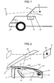
- FIG. 1 is an explanatory diagram showing a configuration of an in-vehicle display apparatus including a display unit according to an exemplary embodiment of the present technique.
- the in-vehicle display apparatus is configured such that display unit 10 for projecting an image is disposed in dashboard 21 of vehicle 20.
- Display unit 10 projects an image on windshield 22 as a light transmissive display member disposed in vehicle 20, and thus forms, on an opposite side of windshield 22 to user 30, virtual image 40 of the image projected by display unit 10.
- User 30 can see, through windshield 22, virtual image 40 of the image projected by display unit 10.
- the chain double-dashed line shown in FIG. 1 represents central optical path L of the projected image, and also in the following description, central optical path L is represented by a chain double-dashed line in the drawings.
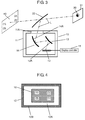
- FIG. 2 is a perspective view showing a configuration of the display unit used in the in-vehicle display apparatus.
- FIG. 2 shows the configuration with a part of a housing of the display unit cut away.
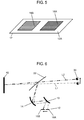
- FIG. 3 is an explanatory diagram showing a schematic configuration of the display unit.
- display unit 10 is configured such that housing 11 having opening 11A houses therein display device 12 for displaying an image and a projection optical system for projecting the image displayed on display device 12 onto windshield 22 as the display member.
- This arrangement enables user 30 to see virtual image 40 of the image through windshield 22 as the display member.
- virtual image 40 of the image can be seen by user 30 from eye box 31 as a previously assumed visible area.
- Opening 11A of housing 11 forms an emitting window through which the projection light from the projection optical system is emitted.
- Opening 11A of housing 11 may be provided with a light transmissive cover made of a transparent resin sheet or the like such so as to close opening 11A.
- display device 12 there is used a liquid crystal display, an organic EL display, a plasma display, or the like, and a predetermined image is displayed in a display area of display device 12, based on an image signal being input from display controller 15.
- the projection optical system includes, on the optical path from display device 12 to windshield 22 as the display member, first mirror 13 as a first reflection member disposed on a display device 12 side and second mirror 14 as a second reflection member disposed on a display member side, that is, on an opening 11A side through which the projection light of the image displayed on display device 12 is emitted.
- opening 11A through which the projection light is emitted has: first edge 11B formed in a circumferential area on a first mirror 13 side of opening 11A; and second edge 11C formed in a circumferential on a second mirror 14 side of opening 11A.
- Display device 12 is disposed such that the display area on which the image is being displayed is located on the first mirror 13 side, with respect to straight line LS connecting first edge 11B and second edge 11C.
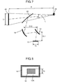
- FIG. 4 is a plan view showing a display surface of the display device.
- rectangular display device 12 has: rectangular display area 12A for displaying predetermined image 16, based on an image signal being input from display controller 15; and non-display area 12B formed in an area surrounding display area 12A.
- image 16 displayed on display device 12 is vertically and horizontally reversed with respect to virtual image 40 displayed by display unit 10.
- Display controller 15 is configured to be able to change the display position of image 16 in display area 12A by controlling the image signal being input to display device 12.
- FIG. 5 is an explanatory diagram showing how the display position of the image displayed on the display device is changed.
- FIG. 6 is an explanatory diagram showing how the image projected by the projection optical system is changed by changing the display position of the image displayed on the display device.
- display controller 15 can control the image signal so that the position of the image displayed on display device 12 is changed from display position 16A to display position 16B.
- the display position is not limited to two display positions 16A and 16B, and can be set to an arbitrary position by display controller 15.
- display unit 10 has a configuration in which the position of the image displayed on display device 12 can be changed by controlling display controller 15, and thus user 30 can see appropriate virtual image 40 depending on the position of the viewpoint of user 30.
- display controller 15 is controlled to adjust the display position of the image displayed on display device 12 so that user 30 can see appropriate virtual image 40; therefore, the mounting error can be corrected by display unit 10 itself.
- display controller 15 can be controlled to adjust display positions 16A and 16B of image 16 displayed on display device 12 so that user 30 can see appropriate virtual image 40.
- the viewpoint of user 30 is located almost at a center of eye box 31 as the visible area. Therefore, when the position of the viewpoint of user 30 has been changed, display controller 15 controls to move display positions 16A and 16B of image 16 displayed on display device 12 so that the viewpoint of user 30 is located almost at a center of eye box 31 as the visible area.
- Vi/Is is preferably equal to or more than two and less than seven, where Vi is a moving amount of a viewpoint area of a user, and Is is a moving amount of image 16 displayed on display device 12. It is more preferable that display controller 15 controls the moving amount of image 16 so that Vi/Is is equal to or more than four and less than six. It is found that if Vi/Is is equal to or more than seven, distortion of the image observed in eye box 31 of user 30 is large, and if Vi/Is is less than two, eye box 31 as the visible area of user 30 is small.
- First mirror 13 as the first reflection member of the projection optical system is disposed vertically above the display surface of display device 12, that is, display area 12A.
- reflection surface 13A for reflecting the image displayed on display device 12 has a free curved convex shape.
- Second mirror 14 as the second reflection member of the projection optical system is disposed, on the optical path reflected by reflection surface 13A of first mirror 13, vertically below windshield 22 as the display member.
- reflection surface 14A having a free curved concave shape faces reflection surface 13A of first mirror 13 and projects the image onto windshield 22 as the display member.
- FIG. 7 is an explanatory diagram showing a positional relationship among the display device of the display unit, the first mirror, the second mirror, the user, and the virtual image.
- FIG. 8 is a plan view showing a positional relationship of the image displayed on the display device. The reference marks shown in FIG. 7 and FIG. 8 are defined below.
- the distances among display device 12, first mirror 13, and second mirror 14 represent lengths on the central optical path.
- D12 is the distance between first mirror 13 and second mirror 14;
- Lv is the vertical length (T ⁇ tan ⁇ ) of virtual image 40;
- T is the distance, on the central optical path, from a pupil of user 30 to virtual image 40;
- ⁇ is the angle in the vertical direction when virtual image 40 is viewed from the pupil of user 30;
- Yv is the vertical length (corresponding to the vertical length of the virtual image) of image 16 displayed on display device 12;
- DL1 is the distance between first mirror 13 and image 16 on display device 12.
- the display apparatus using display unit 10 is arranged such that distance D12 between first mirror 13 and second mirror 14 satisfies 0.2 ⁇ D12/Lv ⁇ 1.3. It is preferable that the display apparatus is arranged such that distance D12 between first mirror 13 and second mirror 14 satisfies 0.5 ⁇ D12/Lv ⁇ 1.0. It is more preferable that the display apparatus is arranged such that an upper limit of distance D12 between first mirror 13 and second mirror 14 satisfies D12/Lv ⁇ 0.9.
- This arrangement enables user 30 to see sufficiently large virtual image 40 even with small display unit 10 in which the distance between first mirror 13 and second mirror 14 is small.
- This arrangement can prevent a curvature of second mirror 14 from becoming large, and thus a screen distortion of virtual image 40 can also be easily corrected. That is, the present exemplary embodiment can realize downsizing of display unit 10.
- the display apparatus of the present exemplary embodiment is also configured such that the relationship between vertical length Yv of image 16 displayed on display device 12 and distance T, on the central optical path, from user 30 to virtual image 40 satisfies 0.03 ⁇ ⁇ (T ⁇ Lv)/Yv ⁇ 0.22.
- the distance from user 30 to virtual image 40 is large, whereby the display apparatus becomes large.
- the relationship ⁇ (T ⁇ Lv)/Yv between vertical length Yv of image 16 and distance T from user 30 to virtual image 40 is less than 0.03, the vertical length of image 16 displayed on display device 12 needs to be large, and as a result, display unit 10 becomes large. That is, according to the present exemplary embodiment, it is possible to realize downsizing of display unit 10 and downsizing of the display apparatus using display unit 10.
- the display apparatus using display unit 10 is configured such that distance D12 between first mirror 13 and second mirror 14 and distance DL1 between first mirror 13 and image 16 on display device 12 satisfy 3.0 ⁇ D12/DL1. It is preferable that the display apparatus is configured such that distance D12 between first mirror 13 and second mirror 14 and distance DL1 between first mirror 13 and image 16 on display device 12 satisfy 3.5 ⁇ D12/DL1 ⁇ 10.0. It is more preferable that the display apparatus is configured such that distance D12 between first mirror 13 and second mirror 14 and distance DL1 between first mirror 13 and image 16 on display device 12 satisfy 5.0 ⁇ D12/DL1 ⁇ 8.0.
- the curvature of second mirror 14 can be prevented from becoming large, whereby the screen distortion of virtual image 40 can be also easily corrected. That is, according to the present exemplary embodiment, it is possible to downsize display unit 10.
- FIG. 9 is an explanatory diagram showing a relationship between the eye box as the visible area of the user and the virtual image which can be seen by the user, in the present exemplary embodiment.
- FIG. 9 is a diagram when virtual image 40 is viewed from a lower left position (3) of eye box 31.
- FIG. 10 is an explanatory diagram showing how the virtual image looks when viewed from different positions (1) to (5) in the eye box as the visible area, in the present exemplary embodiment.
- the visible area is an area in which the user can observe the entire virtual image without any missing part
- the visible area has a rectangular shape of 120 mm width ⁇ 35 mm height, in the present exemplary embodiment.
- the screen distortion is corrected for the entire area of eye box 31 when virtual image 40 is viewed from the positions (1) to (5) in eye box 31.
- user 30 can see satisfactory virtual image 40 from the entire area of eye box 31.
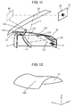
- FIG. 11 is a perspective view showing a configuration of another exemplary embodiment of the display unit used for the in-vehicle display apparatus.
- first light shielding part 11D is provided in a circumferential area on the first mirror 13 side of opening 11A through which the projection light passes
- second light shielding part 11E is provided in a circumferential area on the second mirror 14 side of opening 11A, to have a shape which seems to have been cut and raised from housing 11.
- First light shielding part 11D has first edge 11B
- second light shielding part 11E has second edge 11C.
- Display device 12 is disposed such that the display area for displaying the image is located on the first mirror 13 side, with respect to straight line LS connecting first edge 11B and second edge 11C.
- first light shielding part 11D and second light shielding part 11E are provided, an opening area of opening 11A can be large; thus, large degree of freedom in design is secured.
- display unit 10 for projecting an image is configured such that display device 12 configured to display an image and the projection optical system configured to project the image displayed on display device 12 onto the display member are housed in housing 11 having opening 11A through which projection light is emitted.
- the projection optical system includes, on the optical path from display device 12 to opening 11A, first mirror 13 disposed on the display device 12 side; and second mirror 14 disposed on the opening 11A side.
- First mirror 13 has reflection surface 13A which reflects the image displayed on display device 12 and has a free curved convex shape
- second mirror 14 has reflection surface 14A which projects the image onto the display member and has a free curved concave shape.
- the distance from user 30 to virtual image 40 is not large, and the vertical length of image 16 displayed on display device 12 does not need to be large; thus, it is possible to downsize display unit 10 and the display apparatus using display unit 10.
- reflection surface 13A of first mirror 13 of display unit 10 has a rotationally asymmetric convex shape. With this arrangement, it is possible to successfully correct the screen distortion over the entire viewpoint area of the user. In addition, it is preferable that reflection surface 13A of first mirror 13 has a convex shape in the horizontal direction. This arrangement enables the curvature, in the horizontal direction, of reflection surface 14A of second mirror 14 to increase; thus, the display apparatus can be downsized.
- reflection surface 13A of first mirror 13 may be a toroidal surface having a convex surface in the horizontal direction.
- the "toroidal surface” represents an aspherical surface shape having different curvatures in the horizontal direction and the vertical direction, which are orthogonal to each other.
- reflection surface 13A of first mirror 13 may have a rotationally asymmetric shape having different curvatures in the X-axis direction and the Y-axis direction, as shown in FIG. 12 .
- FIG. 13 is an explanatory diagram showing an example of a mirror whose reflection surface is a free curved surface. As shown in FIG. 13 , the free curved reflection surface is defined as below.
- reflection surface F when vertical reference curve F1 and horizontal reference curve F2 both passing through optical axis C of a central optical path of an image are set, reflection surface F has reflection areas ⁇ 1, ⁇ 2, ⁇ 3, and ⁇ 4 having different curvatures with a point, at which vertical reference curve F1 and horizontal reference curve F2 intersect, as a border.
- the unit of length and the unit of angle in the tables are respectively mm and degree.
- z is a sag amount at a position (x, y) with respect to the axes defining the surface; r is a radius of curvature at the origin of the axes defining the surface; c is a curvature at the origin of the axes defining the surface; k is a conic constant; and Cj is a coefficient of a monomial x m y n .
- the coordinate origin as a reference is the center of the image (display surface) displayed in display device 12; and in the tables, the horizontal direction of the display surface is represented as the X-axis, the vertical direction is represented as the Y-axis, and the direction perpendicular to the display surface is represented as the Z-axis.
- ADE represents an amount by which the mirror is rotated from the Z-axis direction to the Y-axis direction about the X-axis
- BDE represents an amount by which the mirror is rotated from the X-axis direction to the Z-axis direction about the Y-axis
- CDE represents an amount by which the mirror is rotated from the X-axis direction to the Y-axis direction about the Z-axis.
- Table 20 shows examples of the display size of the image, the virtual image size, and the distance from the viewpoint of a user to the virtual image.
- Table 21 shows examples of the numerical values calculated, with reference to FIG. 7 , based on the parameters: D12 indicating the distance between first mirror 13 and second mirror 14; Lv indicating the vertical length (T ⁇ tan ⁇ ) of virtual image 40; and T indicating the distance from the pupil of user 30 to virtual image 40.
- Example 1 Example 2
- Example 3 Example 4
- Example 5 Example 6 Display size X 97.6 97.6 100.0 100.0 40.9 14.4 Y 36.6 36.6 50.0 50.0 20.5 38.4
- Example 1 Example 2
- Example 3 Example 4 Example 5
- Example 6 D12/Lv 0.84 0.86 0.61 0.61 0.89 0.90 ⁇ T ⁇ Lv / Yv 0.10 0.10 0.05 0.05 0.16 0.20
- the present technique is preferably applied to a display apparatus such as a head-up display for in-car use which requires high image quality.
Landscapes
- Physics & Mathematics (AREA)
- General Physics & Mathematics (AREA)
- Optics & Photonics (AREA)
- Engineering & Computer Science (AREA)
- Chemical & Material Sciences (AREA)
- Combustion & Propulsion (AREA)
- Transportation (AREA)
- Mechanical Engineering (AREA)
- Instrument Panels (AREA)
- Transforming Electric Information Into Light Information (AREA)
- Fittings On The Vehicle Exterior For Carrying Loads, And Devices For Holding Or Mounting Articles (AREA)
Abstract
Description
- The present technique relates to a display apparatus in which a display image is projected on a light transmissive display member so that a virtual image of the display image is visible.
-
PTL 1 discloses a head-up display having a curved screen in which a curvature of field of a virtual image is corrected.PTL 2 discloses a head-up display in which a display image is displayed, being divided into two screens. -
- PTL 1: Japanese Laid-Open Patent Publication No.
2013-25205 - PTL 2: Japanese Laid-Open Patent Publication No.
2013-111999 - A display apparatus of the present technique includes a display unit configured to project an image onto a light transmissive display member to form a virtual image of the image projected by the display unit, on an opposite side of the display member to a user. The display unit is configured such that a display device for displaying an image and a projection optical system for projecting the image displayed on the display device onto the display member are housed in a housing having an opening through which projection light is emitted. The projection optical system includes, on an optical path from the display device to the opening, a first reflection member disposed on a display device side and a second reflection member disposed on an opening side. The first reflection member has a reflection surface which reflects the image displayed on the display device and has a convex shape, and the second reflection member has a reflection surface which projects the image onto the display member and has a free curved concave shape. Further, a relationship between a vertical length Yv of the image displayed on the display device and a distance T, on a central optical path, from the user to the virtual image satisfies 0.03 < √(TxLv)/Yv < 0.22, where Lv is a vertical length of the virtual image of the image.
-
-
FIG. 1 is an explanatory diagram showing a configuration of an in-vehicle display apparatus including a display unit according to an exemplary embodiment of the present technique. -
FIG. 2 is a perspective view showing a configuration of a display unit used in the in-vehicle display apparatus. -
FIG. 3 is an explanatory diagram showing a schematic configuration of the display unit. -
FIG. 4 is a plan view showing a display surface of the display device. -
FIG. 5 is an explanatory diagram showing how a display position of an image displayed on the display device is changed. -
FIG. 6 is an explanatory diagram showing how the image projected by a projection optical system is changed by changing the display position of the image displayed on the display device. -
FIG. 7 is an explanatory diagram showing a positional relationship among the display device of the display unit, a first mirror, a second mirror, a user, and the virtual image. -
FIG. 8 is a plan view showing a positional relationship of the image displayed on the display device. -
FIG. 9 is an explanatory diagram showing a relationship between an eye box as a visible area of the user and a virtual image which can be seen by the user, in the present exemplary embodiment. -
FIG. 10 is an explanatory diagram showing how the virtual image looks when viewed from different positions (1) to (5) in the eye box as the visible area, in the present exemplary embodiment. -
FIG. 11 is a perspective view showing a configuration of another exemplary embodiment of the display unit used for the in-vehicle display apparatus. -
FIG. 12 is a perspective view showing another example of the first mirror. -
FIG. 13 is an explanatory diagram showing an example of a mirror having a free curved reflection surface. - In the following, a display unit and a display apparatus according to an exemplary embodiment of the present technique will be described with reference to the drawings. However, the exemplary embodiments will not be described in detail in some cases. For example, in some cases, unnecessarily detailed description on already well-known matters or redundant description on substantially identical configurations will not be made. This is to avoid the description being unnecessarily redundant and to help those skilled in the art to easily understand. Note that the inventor provides the accompanying drawings and the following description to help those skilled in the art to sufficiently understand the present technique, but does not intend to use the drawings or description to limit the subject matters of the claims.
-
FIG. 1 is an explanatory diagram showing a configuration of an in-vehicle display apparatus including a display unit according to an exemplary embodiment of the present technique. - As shown in
FIG. 1 , the in-vehicle display apparatus according to the present exemplary embodiment is configured such thatdisplay unit 10 for projecting an image is disposed indashboard 21 ofvehicle 20.Display unit 10 projects an image onwindshield 22 as a light transmissive display member disposed invehicle 20, and thus forms, on an opposite side ofwindshield 22 touser 30,virtual image 40 of the image projected bydisplay unit 10.User 30 can see, throughwindshield 22,virtual image 40 of the image projected bydisplay unit 10. The chain double-dashed line shown inFIG. 1 represents central optical path L of the projected image, and also in the following description, central optical path L is represented by a chain double-dashed line in the drawings. -
FIG. 2 is a perspective view showing a configuration of the display unit used in the in-vehicle display apparatus.FIG. 2 shows the configuration with a part of a housing of the display unit cut away.FIG. 3 is an explanatory diagram showing a schematic configuration of the display unit. - As shown in
FIG. 2 andFIG. 3 ,display unit 10 according to the present exemplary embodiment is configured such thathousing 11 having opening 11A houses thereindisplay device 12 for displaying an image and a projection optical system for projecting the image displayed ondisplay device 12 ontowindshield 22 as the display member. This arrangement enablesuser 30 to seevirtual image 40 of the image throughwindshield 22 as the display member. Regarding the image projected ontowindshield 22 as the display member,virtual image 40 of the image can be seen byuser 30 fromeye box 31 as a previously assumed visible area. - Opening 11A of
housing 11 forms an emitting window through which the projection light from the projection optical system is emitted. Opening 11A ofhousing 11 may be provided with a light transmissive cover made of a transparent resin sheet or the like such so as to close opening 11A. - As
display device 12, there is used a liquid crystal display, an organic EL display, a plasma display, or the like, and a predetermined image is displayed in a display area ofdisplay device 12, based on an image signal being input fromdisplay controller 15. - In addition, the projection optical system includes, on the optical path from
display device 12 towindshield 22 as the display member,first mirror 13 as a first reflection member disposed on adisplay device 12 side andsecond mirror 14 as a second reflection member disposed on a display member side, that is, on an opening 11A side through which the projection light of the image displayed ondisplay device 12 is emitted. - As shown in
FIG. 2 , inhousing 11 ofdisplay unit 10, opening 11A through which the projection light is emitted has:first edge 11B formed in a circumferential area on afirst mirror 13 side of opening 11A; andsecond edge 11C formed in a circumferential on asecond mirror 14 side of opening 11A.Display device 12 is disposed such that the display area on which the image is being displayed is located on thefirst mirror 13 side, with respect to straight line LS connectingfirst edge 11B andsecond edge 11C. With this arrangement, even if external light enters intodisplay unit 10, entering of the external light into the display area ofdisplay device 12 can be controlled; thus,virtual image 40 of high quality can be formed. -
FIG. 4 is a plan view showing a display surface of the display device. As shown inFIG. 4 ,rectangular display device 12 has:rectangular display area 12A for displayingpredetermined image 16, based on an image signal being input fromdisplay controller 15; and non-displayarea 12B formed in an area surroundingdisplay area 12A. Further,image 16 displayed ondisplay device 12 is vertically and horizontally reversed with respect tovirtual image 40 displayed bydisplay unit 10. Marks (1), (2), (3), and (4) added onvirtual image 40 shown inFIG. 3 to indicate positions and marks (1), (2), (3), and (4) added onimage 16 shown inFIG. 4 to indicate positions illustrate thatimage 16 displayed ondisplay device 12 is reversed with respect tovirtual image 40 formed bydisplay unit 10. -
Display controller 15 is configured to be able to change the display position ofimage 16 indisplay area 12A by controlling the image signal being input to displaydevice 12. -
FIG. 5 is an explanatory diagram showing how the display position of the image displayed on the display device is changed.FIG. 6 is an explanatory diagram showing how the image projected by the projection optical system is changed by changing the display position of the image displayed on the display device. - As shown in
FIG. 5 ,display controller 15 can control the image signal so that the position of the image displayed ondisplay device 12 is changed fromdisplay position 16A to displayposition 16B. Note that the display position is not limited to twodisplay positions display controller 15. - As shown in
FIG. 6 , when the position of the image is controlled to be changed fromdisplay position 16A to displayposition 16B, the central optical path of the projected image is changed from L1 to L2, whereby the position of the viewpoint ofuser 30 viewingvirtual image 40 is changed. - That is,
display unit 10 according to the present exemplary embodiment has a configuration in which the position of the image displayed ondisplay device 12 can be changed by controllingdisplay controller 15, and thususer 30 can see appropriatevirtual image 40 depending on the position of the viewpoint ofuser 30. For example, whendisplay unit 10 is mounted invehicle 20, a mounting error ofdisplay unit 10 is caused. Withdisplay unit 10 of the present exemplary embodiment,display controller 15 is controlled to adjust the display position of the image displayed ondisplay device 12 so thatuser 30 can see appropriatevirtual image 40; therefore, the mounting error can be corrected bydisplay unit 10 itself. In addition, whenuser 30 is changed, the position of the viewpoint ofuser 30 may change. In that case,display controller 15 can be controlled to adjustdisplay positions image 16 displayed ondisplay device 12 so thatuser 30 can see appropriatevirtual image 40. - Incidentally, in order to enable
user 30 to see appropriatevirtual image 40 in the display apparatus of the present exemplary embodiment, it is preferable that the viewpoint ofuser 30 is located almost at a center ofeye box 31 as the visible area. Therefore, when the position of the viewpoint ofuser 30 has been changed,display controller 15 controls to movedisplay positions image 16 displayed ondisplay device 12 so that the viewpoint ofuser 30 is located almost at a center ofeye box 31 as the visible area. - The results of conducted experiments show that Vi/Is is preferably equal to or more than two and less than seven, where Vi is a moving amount of a viewpoint area of a user, and Is is a moving amount of
image 16 displayed ondisplay device 12. It is more preferable thatdisplay controller 15 controls the moving amount ofimage 16 so that Vi/Is is equal to or more than four and less than six. It is found that if Vi/Is is equal to or more than seven, distortion of the image observed ineye box 31 ofuser 30 is large, and if Vi/Is is less than two,eye box 31 as the visible area ofuser 30 is small. -
First mirror 13 as the first reflection member of the projection optical system is disposed vertically above the display surface ofdisplay device 12, that is,display area 12A. Infirst mirror 13,reflection surface 13A for reflecting the image displayed ondisplay device 12 has a free curved convex shape.Second mirror 14 as the second reflection member of the projection optical system is disposed, on the optical path reflected byreflection surface 13A offirst mirror 13, vertically belowwindshield 22 as the display member. Insecond mirror 14,reflection surface 14A having a free curved concave shape facesreflection surface 13A offirst mirror 13 and projects the image ontowindshield 22 as the display member. - Next, arrangement of
display device 12,first mirror 13, andsecond mirror 14 indisplay unit 10 will be described. -
FIG. 7 is an explanatory diagram showing a positional relationship among the display device of the display unit, the first mirror, the second mirror, the user, and the virtual image.FIG. 8 is a plan view showing a positional relationship of the image displayed on the display device. The reference marks shown inFIG. 7 and FIG. 8 are defined below. The distances amongdisplay device 12,first mirror 13, andsecond mirror 14 represent lengths on the central optical path. - D12 is the distance between
first mirror 13 andsecond mirror 14;
Lv is the vertical length (T×tanθ) ofvirtual image 40;
T is the distance, on the central optical path, from a pupil ofuser 30 tovirtual image 40;
θ is the angle in the vertical direction whenvirtual image 40 is viewed from the pupil ofuser 30;
Yv is the vertical length (corresponding to the vertical length of the virtual image) ofimage 16 displayed ondisplay device 12; and
DL1 is the distance betweenfirst mirror 13 andimage 16 ondisplay device 12. - The display apparatus using
display unit 10 according to the present exemplary embodiment is arranged such that distance D12 betweenfirst mirror 13 andsecond mirror 14 satisfies 0.2 < D12/Lv < 1.3. It is preferable that the display apparatus is arranged such that distance D12 betweenfirst mirror 13 andsecond mirror 14 satisfies 0.5 < D12/Lv < 1.0. It is more preferable that the display apparatus is arranged such that an upper limit of distance D12 betweenfirst mirror 13 andsecond mirror 14 satisfies D12/Lv < 0.9. - This arrangement enables
user 30 to see sufficiently largevirtual image 40 even withsmall display unit 10 in which the distance betweenfirst mirror 13 andsecond mirror 14 is small. This arrangement can prevent a curvature ofsecond mirror 14 from becoming large, and thus a screen distortion ofvirtual image 40 can also be easily corrected. That is, the present exemplary embodiment can realize downsizing ofdisplay unit 10. - The display apparatus of the present exemplary embodiment is also configured such that the relationship between vertical length Yv of
image 16 displayed ondisplay device 12 and distance T, on the central optical path, fromuser 30 tovirtual image 40 satisfies 0.03 < √(T×Lv)/Yv < 0.22. - Here, in the present exemplary embodiment, if the relationship √(T×Lv)/Yv between vertical length Yv of
image 16 and distance T fromuser 30 tovirtual image 40 is more than 0.22, the distance fromuser 30 tovirtual image 40 is large, whereby the display apparatus becomes large. On the other hand, if the relationship √(T×Lv)/Yv between vertical length Yv ofimage 16 and distance T fromuser 30 tovirtual image 40 is less than 0.03, the vertical length ofimage 16 displayed ondisplay device 12 needs to be large, and as a result,display unit 10 becomes large. That is, according to the present exemplary embodiment, it is possible to realize downsizing ofdisplay unit 10 and downsizing of the display apparatus usingdisplay unit 10. - In addition, the display apparatus using
display unit 10 according to the present exemplary embodiment is configured such that distance D12 betweenfirst mirror 13 andsecond mirror 14 and distance DL1 betweenfirst mirror 13 andimage 16 ondisplay device 12 satisfy 3.0 < D12/DL1. It is preferable that the display apparatus is configured such that distance D12 betweenfirst mirror 13 andsecond mirror 14 and distance DL1 betweenfirst mirror 13 andimage 16 ondisplay device 12 satisfy 3.5 < D12/DL1 < 10.0. It is more preferable that the display apparatus is configured such that distance D12 betweenfirst mirror 13 andsecond mirror 14 and distance DL1 betweenfirst mirror 13 andimage 16 ondisplay device 12 satisfy 5.0 < D12/DL1 < 8.0. - In the present exemplary embodiment, by configuring such that distance D12 between
first mirror 13 andsecond mirror 14 and distance DL1 betweenfirst mirror 13 andimage 16 ondisplay device 12 satisfy 3.0 < D12/DL1, the curvature ofsecond mirror 14 can be prevented from becoming large, whereby the screen distortion ofvirtual image 40 can be also easily corrected. That is, according to the present exemplary embodiment, it is possible to downsizedisplay unit 10. -
FIG. 9 is an explanatory diagram showing a relationship between the eye box as the visible area of the user and the virtual image which can be seen by the user, in the present exemplary embodiment.FIG. 9 is a diagram whenvirtual image 40 is viewed from a lower left position (3) ofeye box 31. -
FIG. 10 is an explanatory diagram showing how the virtual image looks when viewed from different positions (1) to (5) in the eye box as the visible area, in the present exemplary embodiment. Here, the visible area (eye box) is an area in which the user can observe the entire virtual image without any missing part, and the visible area (eye box) has a rectangular shape of 120 mm width × 35 mm height, in the present exemplary embodiment. - As shown
FIG. 10 , with the display apparatus according to the present exemplary embodiment, the screen distortion is corrected for the entire area ofeye box 31 whenvirtual image 40 is viewed from the positions (1) to (5) ineye box 31. In other words,user 30 can see satisfactoryvirtual image 40 from the entire area ofeye box 31. -
FIG. 11 is a perspective view showing a configuration of another exemplary embodiment of the display unit used for the in-vehicle display apparatus. In the present exemplary embodiment, as shown inFIG. 11 , inhousing 11 ofdisplay unit 10, firstlight shielding part 11D is provided in a circumferential area on thefirst mirror 13 side of opening 11A through which the projection light passes, and secondlight shielding part 11E is provided in a circumferential area on thesecond mirror 14 side ofopening 11A, to have a shape which seems to have been cut and raised fromhousing 11. Firstlight shielding part 11D hasfirst edge 11B, and secondlight shielding part 11E hassecond edge 11C.Display device 12 is disposed such that the display area for displaying the image is located on thefirst mirror 13 side, with respect to straight line LS connectingfirst edge 11B andsecond edge 11C. - With this arrangement, even if external light enters into
display unit 10, entering of the external light into the display area ofdisplay device 12 can be controlled; thus,virtual image 40 of high quality can be formed. In addition, with the present exemplary embodiment, since firstlight shielding part 11D and secondlight shielding part 11E are provided, an opening area ofopening 11A can be large; thus, large degree of freedom in design is secured. - As described above, according to the present technique,
display unit 10 for projecting an image is configured such thatdisplay device 12 configured to display an image and the projection optical system configured to project the image displayed ondisplay device 12 onto the display member are housed inhousing 11 havingopening 11A through which projection light is emitted. The projection optical system includes, on the optical path fromdisplay device 12 toopening 11A,first mirror 13 disposed on thedisplay device 12 side; andsecond mirror 14 disposed on theopening 11A side.First mirror 13 hasreflection surface 13A which reflects the image displayed ondisplay device 12 and has a free curved convex shape, andsecond mirror 14 hasreflection surface 14A which projects the image onto the display member and has a free curved concave shape. Further, the relationship between vertical length Yv ofimage 16 displayed ondisplay device 12 and distance T, on the central optical path, fromuser 30 tovirtual image 40 satisfies 0.03 < √(T×Lv)/Yv < 0.22, where Lv is the vertical length ofvirtual image 40 of the image. - With this arrangement, the distance from
user 30 tovirtual image 40 is not large, and the vertical length ofimage 16 displayed ondisplay device 12 does not need to be large; thus, it is possible to downsizedisplay unit 10 and the display apparatus usingdisplay unit 10. - In addition, with the present technique, it is possible to successfully correct the screen distortion occurred in
windshield 22 as the display member having a predetermined curvature; thus, the virtual image of the image formed on the opposite side of the display member to the user has a small screen distortion, whereby the user can see the virtual image without feeling strange. - Here,
reflection surface 13A offirst mirror 13 ofdisplay unit 10 according to the present technique has a rotationally asymmetric convex shape. With this arrangement, it is possible to successfully correct the screen distortion over the entire viewpoint area of the user. In addition, it is preferable thatreflection surface 13A offirst mirror 13 has a convex shape in the horizontal direction. This arrangement enables the curvature, in the horizontal direction, ofreflection surface 14A ofsecond mirror 14 to increase; thus, the display apparatus can be downsized. - Although the above exemplary embodiment is described using the case where
reflection surface 13A offirst mirror 13 has a free curved convex shape,reflection surface 13A may be a toroidal surface having a convex surface in the horizontal direction. Note that the "toroidal surface" represents an aspherical surface shape having different curvatures in the horizontal direction and the vertical direction, which are orthogonal to each other. - Further,
reflection surface 13A offirst mirror 13 may have a rotationally asymmetric shape having different curvatures in the X-axis direction and the Y-axis direction, as shown inFIG. 12 . -
FIG. 13 is an explanatory diagram showing an example of a mirror whose reflection surface is a free curved surface. As shown inFIG. 13 , the free curved reflection surface is defined as below. - In reflection surface F, when vertical reference curve F1 and horizontal reference curve F2 both passing through optical axis C of a central optical path of an image are set, reflection surface F has reflection areas θ1, θ2, θ3, and θ4 having different curvatures with a point, at which vertical reference curve F1 and horizontal reference curve F2 intersect, as a border.
- In the following, specific examples will be described with respect to the display apparatus according to the present technique. Note that, in the examples to be described below, the unit of length and the unit of angle in the tables are respectively mm and degree. In addition, the free curved surface is defined by the following mathematical expression.

- In
Mathematical Expression 1, z is a sag amount at a position (x, y) with respect to the axes defining the surface; r is a radius of curvature at the origin of the axes defining the surface; c is a curvature at the origin of the axes defining the surface; k is a conic constant; and Cj is a coefficient of a monomial xmyn. - Further, in the examples, the coordinate origin as a reference is the center of the image (display surface) displayed in
display device 12; and in the tables, the horizontal direction of the display surface is represented as the X-axis, the vertical direction is represented as the Y-axis, and the direction perpendicular to the display surface is represented as the Z-axis. - In the tables,
surface number 1 represents the display surface ofdisplay device 12;surface number 2 representsfirst mirror 13;surface number 3 represents second mirror;surface number 4 representswindshield 22; andsurface number 5 represents the viewpoint of a user. Further, in the eccentricity data, ADE represents an amount by which the mirror is rotated from the Z-axis direction to the Y-axis direction about the X-axis, BDE represents an amount by which the mirror is rotated from the X-axis direction to the Z-axis direction about the Y-axis, and CDE represents an amount by which the mirror is rotated from the X-axis direction to the Y-axis direction about the Z-axis. -
Table 1 Surface number X curvature Y curvature 2 603.2021 2654.4 Table 2 Surface number Coefficient of polynomial 3 C1 0.00000E+00 C19 4.87235E-12 C37 0.00000E+00 C55 0.00000E+00 C2 -3.53809E-02 C20 -1.22754E-10 C38 0.00000E+00 C56 0.00000E+00 C3 1.28613E-02 C21 3.76537E-10 C39 0.00000E+00 C57 0.00000E+00 C4 6.92444E-04 C22 -2.41643E-14 C40 0.00000E+00 C58 0.00000E+00 C5 5.21278E-06 C23 5.70609E-14 C41 0.00000E+00 C59 0.00000E+00 C6 2.72060E-04 C24 -1.55312E-13 C42 0.00000E+00 C60 0.00000E+00 C7 -3.35289E-07 C25 5.63778E-13 C43 0.00000E+00 C61 0.00000E+00 C8 -2.38015E-07 C26 -1.72194E-12 C44 0.00000E+00 C62 0.00000E+00 C9 -1.86100E-07 C27 3.64513E-12 C45 0.00000E+00 C63 0.00000E+00 C10 -1.06353E-06 C28 -6.10356E-12 C46 0.00000E+00 C64 0.00000E+00 C11 2.39274E-09 C29 0.00000E+00 C47 0.00000E+00 C65 0.00000E+00 C12 -1.23325E-10 C30 0.00000E+00 C48 0.00000E+00 C66 0.00000E+00 C13 5.27888E-09 C31 0.00000E+00 C49 0.00000E+00 C14 -7.12437E-09 C32 0.00000E+00 C50 0.00000E+00 C15 1.34163E-08 C33 0.00000E+00 C51 0.00000E+00 C16 9.51762E-13 C34 0.00000E+00 C52 0.00000E+00 C17 -1.48362E-11 C35 0.00000E+00 C53 0.00000E+00 C18 9.29390E-12 C36 0.00000E+00 C54 0.00000E+00 Table 3 Surface number Shape Eccentricity data X Y Z ADE BDE CDE 1 0 0 0 0 0 0 2 Toroidal -1.836 2.033 48.083 -30.835 2.234 0.577 3 Free curved surface 1.602 116.142 -7.383 -41.903 2.082 0.995 4 Toroidal 12.044 5.809 256.018 43.684 5.817 2.521 5 203.349 -755.414 511.993 109.093 6.642 -8.320 -
Table 4 Surface number Coefficient of polynomial 2 C1 0.00000E+00 C19 2.41168E-11 C37 0.00000E+00 C55 0.00000E+00 C2 -2.37943E-02 C20 -1.90336E-10 C38 0.00000E+00 C56 0.00000E+00 C3 1.69540E-02 C21 2.95788E-10 C39 0.00000E+00 C57 0.00000E+00 C4 6.95718E-04 C22 -1.14425E-14 C40 0.00000E+00 C58 0.00000E+00 C5 2.53616E-05 C23 9.02420E-14 C41 0.00000E+00 C59 0.00000E+00 C6 2.93214E-04 C24 -1.18772E-13 C42 0.00000E+00 C60 0.00000E+00 C7 -4.97930E-07 C25 2.31335E-13 C43 0.00000E+00 C61 0.00000E+00 C8 -6.24744E-07 C26 -9.13190E-13 C44 0.00000E+00 C62 0.00000E+00 C9 -6.72213E-07 C27 3.19186E-12 C45 0.00000E+00 C63 0.00000E+00 C10 -4.12374E-07 C28 -4.36103E-12 C46 0.00000E+00 C64 0.00000E+00 C11 1.40407E-09 C29 0.00000E+00 C47 0.00000E+00 C65 0.00000E+00 C12 -3.73506E-10 C30 0.00000E+00 C48 0.00000E+00 C66 0.00000E+00 C13 4.88892E-09 C31 0.00000E+00 C49 0.00000E+00 C14 -3.10558E-09 C32 0.00000E+00 C50 0.00000E+00 C15 8.54164E-09 C33 0.00000E+00 C51 0.00000E+00 C16 -8.95059E-13 C34 0.00000E+00 C52 0.00000E+00 C17 -1.47160E-11 C35 0.00000E+00 C53 0.00000E+00 C18 -1.83957E-12 C36 0.00000E+00 C54 0.00000E+00 3 C1 0.00000E+00 C19 -1.44244E-10 C37 0.00000E+00 C55 0.00000E+00 C2 5.55069E-02 C20 -1.13270E-09 C38 0.00000E+00 C56 0.00000E+00 C3 2.88012E-02 C21 5.86354E-10 C39 0.00000E+00 C57 0.00000E+00 C4 1.79659E-04 C22 -7.19280E-13 C40 0.00000E+00 C58 0.00000E+00 C5 -2.29361 E-05 C23 7.83822E-12 C41 0.00000E+00 C59 0.00000E+00 C6 -4.44075E-04 C24 5.78822E-14 C42 0.00000E+00 C60 0.00000E+00 C7 -2.94434E-06 C25 3.58110E-12 C43 0.00000E+00 C61 0.00000E+00 C8 -4.46411 E-06 C26 -9.17880E-12 C44 0.00000E+00 C62 0.00000E+00 C9 -2.97119E-06 C27 1.87450E-11 C45 0.00000E+00 C63 0.00000E+00 C10 3.34442E-06 C28 -7.35955E-11 C46 0.00000E+00 C64 0.00000E+00 C11 -1.18069E-08 C29 9.28492E-15 C47 0.00000E+00 C65 0.00000E+00 C12 -2.24904E-08 C30 -1.66169E-14 C48 0.00000E+00 C66 0.00000E+00 C13 3.83585E-08 C31 -3.33447E-14 C49 0.00000E+00 C14 -5.06094E-09 C32 -6.11151E-14 C50 0.00000E+00 C15 1.15003E-07 C33 -7.48046E-14 C51 0.00000E+00 C16 -4.48742E-11 C34 1.58819E-13 C52 0.00000E+00 C17 6.52135E-11 C35 6.56811 E-13 C53 0.00000E+00 C18 -2.66825E-10 C36 1.08622E-14 C54 0.00000E+00 Table 5 Surface number Shape Eccentricity data X Y Z ADE BDE CDE 1 0 0 0 0 0 0 2 Free curved surface -0.377 6.917 47.660 -27.080 0.566 -0.024 3 Free curved surface 0.676 119.411 -11.103 -40.435 0.556 0.108 4 Toroidal 21.177 17.593 255.181 45.060 6.490 4.825 5 245.397 -728.488 528.440 110.670 9.006 -7.980 -
Table 6 Surface number X curvature Y curvature 2 711.0349 628.2919 Table 7 Surface number Coefficient of polynomial 2 C1 -7.74625E+00 C19 2.49212E-11 C37 9.30119E-19 C55 5.72526E-18 C2 -1.73760E-02 C20 5.59040E-11 C38 1.67547E-18 C56 -1.43014E-22 C3 -3.54173E-02 C21 2.13743E-11 C39 2.20897E-19 C57 -1.67215E-23 C4 5.57437E-04 C22 -1.14501E-15 C40 -2.43948E-17 C58 -4.39331 E-22 C5 4.91213E-05 C23 -2.39542E-14 C41 -2.78455E-18 C59 5.33256E-22 C6 2.72918E-04 C24 5.34863E-14 C42 -9.89926E-18 C60 8.68017E-22 C7 6.70001E-08 C25 5.49852E-13 C43 2.10560E-17 C61 -1.46669E-21 C8 -3.68481 E-07 C26 -3.26715E-13 C44 4.10178E-16 C62 4.57527E-21 C9 -7.18698E-08 C27 -9.84776E-13 C45 3.85909E-16 C63 -3.00340E-21 C10 -1.97712E-07 C28 -9.93883E-13 C46 1.40656E-20 C64 -2.54986E-20 C11 1.61710E-09 C29 6.07330E-16 C47 -1.45731 E-22 C65 1.92867E-21 C12 4.96069E-11 C30 -1.17494E-16 C48 8.90634E-20 C66 -8.45424E-20 C13 3.19279E-09 C31 -8.05043E-16 C49 9.38960E-20 C14 -2.68371 E-09 C32 -2.62095E-15 C50 -2.95915E-19 C15 5.40272E-09 C33 1.69253E-15 C51 -4.41647E-20 C16 -1.87291E-11 C34 -7.25278E-15 C52 6.92333E-19 C17 -1.72096E-12 C35 -1.56103E-14 C53 1.81955E-18 C18 -5.14945E-12 C36 -2.44877E-14 C54 -1.17293E-18 Table 8 Surface number Shape Eccentricity data X Y Z ADE BDE CDE 1 0 0 0 0 0 0 2 Toroidal 2.933 1.054 45.949 -39.465 -1.082 -4.335 3 Free curved surface 8.680 162.225 18.038 -58.032 0.358 -4.453 4 Toroidal 59.478 20.245 245.022 31.889 2.347 1.388 5 168.515 -800.395 336.634 96.038 4.685 -6.441 -
Table 9 Surface number Coefficient of polynomial 2 C1 0.00000E+00 C19 -1.28160E-10 C37 0.00000E+00 C55 0.00000E+00 C2 -1.88798E-03 C20 -4.88795E-10 C38 0.00000E+00 C56 0.00000E+00 C3 -1.16384E-02 C21 4.65021 E-11 C39 0.00000E+00 C57 0.00000E+00 C4 -2.20104E-05 C22 1.79401 E-12 C40 0.00000E+00 C58 0.00000E+00 C5 -5.60173E-05 C23 9.52643E-13 C41 0.00000E+00 C59 0.00000E+00 C6 -8.71798E-05 C24 1.70778E-12 C42 0.00000E+00 C60 0.00000E+00 C7 -1.37429E-06 C25 9.42122E-13 C43 0.00000E+00 C61 0.00000E+00 C8 -2.39788E-06 C26 2.23806E-12 C44 0.00000E+00 C62 0.00000E+00 C9 -4.08949E-06 C27 -1.08763E-12 C45 0.00000E+00 C63 0.00000E+00 C10 1.08131E-06 C28 4.61590E-12 C46 0.00000E+00 C64 0.00000E+00 C11 -8.45057E-09 C29 0.00000E+00 C47 0.00000E+00 C65 0.00000E+00 C12 4.32821 E-09 C30 0.00000E+00 C48 0.00000E+00 C66 0.00000E+00 C13 2.24025E-08 C31 0.00000E+00 C49 0.00000E+00 C14 1.51402E-08 C32 0.00000E+00 C50 0.00000E+00 C15 -5.48935E-09 C33 0.00000E+00 C51 0.00000E+00 C16 -6.11656E-11 C34 0.00000E+00 C52 0.00000E+00 C17 -2.97250E-10 C35 0.00000E+00 C53 0.00000E+00 C18 -1.38852E-10 C36 0.00000E+00 C54 0.00000E+00 3 C1 -4.13454E+00 C19 2.13613E-11 C37 5.30403E-19 C55 5.51614E-18 C2 -1.25103E-02 C20 4.26555E-11 C38 1.84207E-18 C56 -1.19051 E-22 C3 -3.33999E-02 C21 3.42848E-11 C39 -9.20942E-19 C57 -7.26209E-24 C4 5.57897E-04 C22 -2.89755E-14 C40 -2.48408E-17 C58 -4.55573E-22 C5 4.81348E-05 C23 -2.72475E-14 C41 3.64698E-18 C59 3.97866E-22 C6 2.73964E-04 C24 3.73200E-14 C42 -6.26492E-18 C60 7.64242E-22 C7 -9.02684E-08 C25 4.71097E-13 C43 1.51546E-17 C61 -1.46295E-21 C8 -5.62752E-07 C26 -2.32457E-13 C44 3.47700E-16 C62 3.58028E-21 C9 -4.16046E-07 C27 -1.07144E-12 C45 3.67879E-16 C63 -4.69101 E-21 C10 -1.75022E-07 C28 -7.46368E-13 C46 1.68651E-20 C64 -2.21322E-20 C11 1.75704E-09 C29 5.65531 E-16 C47 9.24582E-22 C65 8.72864E-21 C12 3.90988E-10 C30 -2.56218E-16 C48 1.00871E-19 C66 -7.82403E-20 C13 2.80206E-09 C31 -6.36585E-16 C49 8.61703E-20 C14 -1.45904E-09 C32 -1.97885E-15 C50 -2.61479E-19 C15 4.27866E-09 C33 1.74136E-15 C51 6.79566E-20 C16 -1.86021E-11 C34 -7.29656E-15 C52 6.59543E-19 C17 -6.34215E-13 C35 -1.68610E-14 C53 1.68901 E-18 C18 -1.08581E-11 C36 -2.53896E-14 C54 -9.15230E-19 Table 10 Surface number Shape Eccentricity data X Y Z ADE BDE CDE 1 0 0 0 0 0 0 2 Free curved surface -3.139 4.384 51.009 -33.675 5.137 -0.818 3 Free curved surface 9.725 159.210 1.656 -50.376 5.155 0.690 4 Toroidal 37.961 47.706 253.040 39.594 7.745 -3.307 5 119.229 -754.992 459.930 103.782 2.822 -13.350 -
Table 11 Surface number Coefficient of polynomial 2 C1 0.00000E+00 C19 8.54316E-10 C37 0.00000E+00 C55 0.00000E+00 C2 7.43401E-02 C20 -3.00716E-08 C38 0.00000E+00 C56 0.00000E+00 C3 1.26031E-01 C21 8.57783E-08 C39 0.00000E+00 C57 0.00000E+00 C4 6.47921 E-04 C22 -2.48786E-11 C40 0.00000E+00 C58 0.00000E+00 C5 4.33203E-05 C23 6.08772E-11 C41 0.00000E+00 C59 0.00000E+00 C6 -9.13686E-06 C24 -7.51368E-11 C42 0.00000E+00 C60 0.00000E+00 C7 2.70405E-06 C25 2.77465E-11 C43 0.00000E+00 C61 0.00000E+00 C8 -2.15690E-05 C26 -5.82084E-11 C44 0.00000E+00 C62 0.00000E+00 C9 -1.00719E-05 C27 -3.76834E-10 C45 0.00000E+00 C63 0.00000E+00 C10 3.62560E-05 C28 8.58741E-10 C46 0.00000E+00 C64 0.00000E+00 C11 -1.28051 E-07 C29 0.00000E+00 C47 0.00000E+00 C65 0.00000E+00 C12 -7.41791 E-08 C30 0.00000E+00 C48 0.00000E+00 C66 0.00000E+00 C13 1.95578E-07 C31 0.00000E+00 C49 0.00000E+00 C14 -8.83249E-07 C32 0.00000E+00 C50 0.00000E+00 C15 3.04264E-06 C33 0.00000E+00 C51 0.00000E+00 C16 -1.63944E-09 C34 0.00000E+00 C52 0.00000E+00 C17 5.02021E-09 C35 0.00000E+00 C53 0.00000E+00 C18 3.61341E-09 C36 0.00000E+00 C54 0.00000E+00 3 C1 0.00000E+00 C19 1.05313E-10 C37 0.00000E+00 C55 0.00000E+00 C2 7.52284E-02 C20 -4.81729E-11 C38 0.00000E+00 C56 0.00000E+00 C3 -3.30535E-02 C21 2.49310E-10 C39 0.00000E+00 C57 0.00000E+00 C4 8.44337E-04 C22 -1.70460E-13 C40 0.00000E+00 C58 0.00000E+00 C5 6.09928E-05 C23 -8.10118E-14 C41 0.00000E+00 C59 0.00000E+00 C6 4.14469E-04 C24 -2.61025E-13 C42 0.00000E+00 C60 0.00000E+00 C7 7.24104E-07 C25 -2.44547E-13 C43 0.00000E+00 C61 0.00000E+00 C8 -1.80204E-06 C26 8.29562E-13 C44 0.00000E+00 C62 0.00000E+00 C9 3.80002E-07 C27 -2.79408E-13 C45 0.00000E+00 C63 0.00000E+00 C10 -6.31093E-07 C28 9.61641E-13 C46 0.00000E+00 C64 0.00000E+00 C11 1.57841E-09 C29 0.00000E+00 C47 0.00000E+00 C65 0.00000E+00 C12 -3.45145E-09 C30 0.00000E+00 C48 0.00000E+00 C66 0.00000E+00 C13 7.12120E-09 C31 0.00000E+00 C49 0.00000E+00 C14 -4.93262E-09 C32 0.00000E+00 C50 0.00000E+00 C15 2.35792E-08 C33 0.00000E+00 C51 0.00000E+00 C16 -1.54142E-11 C34 0.00000E+00 C52 0.00000E+00 C17 -3.73411 E-11 C35 0.00000E+00 C53 0.00000E+00 C18 -3.24326E-11 C36 0.00000E+00 C54 0.00000E+00 Table 12 Surface number Shape Eccentricity data X Y Z ADE BDE CDE 1 0 0 0 0 0 0 2 Free curved surface 3.163 19.185 38.804 -30.903 -2.266 -3.512 3 Free curved surface 6.486 129.959 34.777 -62.496 -0.087 -4.178 4 Toroidal 1.181 32.392 161.303 26.936 -5.181 -5.854 5 -168.219 -775.561 126.260 85.317 -12.157 8.390 -
Table 13 Surface number Coefficient of polynomial 2 C1 5.31393E+00 C19 4.18832E-08 C37 -6.59034E-15 C55 0.00000E+00 C2 6.14628E-02 C20 -1.57336E-07 C38 -3.14026E-14 C56 0.00000E+00 C3 4.64893E-01 C21 2.09544E-07 C39 -1.17757E-14 C57 0.00000E+00 C4 1.79720E-03 C22 -4.57278E-10 C40 -1.12045E-13 C58 0.00000E+00 C5 1.12476E-04 C23 -9.57855E-10 C41 -3.18189E-13 C59 0.00000E+00 C6 -4.01159E-04 C24 2.75575E-10 C42 1.10232E-13 C60 0.00000E+00 C7 3.25630E-05 C25 1.64775E-09 C43 4.23078E-13 C61 0.00000E+00 C8 4.60919E-06 C26 6.44462E-11 C44 1.00736E-12 C62 0.00000E+00 C9 -6.03291 E-05 C27 -4.46906E-10 C45 -9.14181 E-13 C63 0.00000E+00 C10 -3.58176E-05 C28 2.14478E-09 C46 0.00000E+00 C64 0.00000E+00 C11 -3.92909E-07 C29 -3.42160E-12 C47 0.00000E+00 C65 0.00000E+00 C12 7.98664E-07 C30 -1.09891E-11 C48 0.00000E+00 C66 0.00000E+00 C13 1.72870E-06 C31 -4.89577E-12 C49 0.00000E+00 C14 -5.87419E-06 C32 -3.37324E-12 C50 0.00000E+00 C15 3.61494E-06 C33 1.53945E-12 C51 0.00000E+00 C16 -2.52222E-08 C34 1.01476E-11 C52 0.00000E+00 C17 -1.72663E-08 C35 6.54663E-11 C53 0.00000E+00 C18 7.33649E-08 C36 -5.37173E-11 C54 0.00000E+00 3 C1 0.00000E+00 C19 1.17932E-10 C37 8.18620E-18 C55 0.00000E+00 C2 2.08429E-02 C20 2.38981E-10 C38 -6.90889E-18 C56 0.00000E+00 C3 1.26733E-01 C21 1.05279E-09 C39 4.21005E-18 C57 0.00000E+00 C4 1.60031E-03 C22 8.16294E-14 C40 -4.25062E-17 C58 0.00000E+00 C5 -7.79659E-05 C23 -4.87975E-13 C41 1.97423E-16 C59 0.00000E+00 C6 1.12460E-03 C24 -7.68740E-13 C42 2.62493E-17 C60 0.00000E+00 C7 9.69798E-07 C25 3.10216E-13 C43 7.93750E-16 C61 0.00000E+00 C8 -9.17625E-07 C26 -1.27347E-12 C44 1.57455E-16 C62 0.00000E+00 C9 1.62879E-06 C27 -3.78998E-12 C45 1.15341 E-15 C63 0.00000E+00 C10 3.34641 E-07 C28 -8.27569E-12 C46 0.00000E+00 C64 0.00000E+00 C11 1.67478E-09 C29 2.09554E-15 C47 0.00000E+00 C65 0.00000E+00 C12 1.62408E-09 C30 -2.43596E-15 C48 0.00000E+00 C66 0.00000E+00 C13 -1.95545E-09 C31 2.48185E-15 C49 0.00000E+00 C14 -1.00740E-08 C32 -1.04840E-14 C50 0.00000E+00 C15 -3.43339E-08 C33 1.81644E-14 C51 0.00000E+00 C16 -8.78711E-12 C34 -4.60001 E-14 C52 0.00000E+00 C17 -2.95545E-11 C35 6.00041 E-15 C53 0.00000E+00 C18 -1.72777E-10 C36 -1.03430E-13 C54 0.00000E+00 Table 14 Surface number Shape Eccentricity data X Y Z ADE BDE CDE 1 0 0 0 0 0 0 2 Free curved surface 7.045 22.397 30.974 1.945 -13.108 0.890 3 Free curved surface -10.138 67.640 -41.130 -21.652 -12.395 -4.389 4 Toroidal -28.813 29.813 232.960 57.727 -10.200 8.929 5 -17.199 -635.508 674.614 123.092 0.655 20.204 -
Table 15 Surface number X curvature Y curvature 2 603.2021 2654.4 Table 16 Surface number Coefficient of polynomial 3 C1 0.00000E+00 C19 4.87235E-12 C37 0.00000E+00 C55 0.00000E+00 C2 -3.53809E-02 C20 -1.22754E-10 C38 0.00000E+00 C56 0.00000E+00 C3 1.28613E-02 C21 3.76537E-10 C39 0.00000E+00 C57 0.00000E+00 C4 6.92444E-04 C22 -2.41643E-14 C40 0.00000E+00 C58 0.00000E+00 C5 5.21278E-06 C23 5.70609E-14 C41 0.00000E+00 C59 0.00000E+00 C6 2.72060E-04 C24 -1.55312E-13 C42 0.00000E+00 C60 0.00000E+00 C7 -3.35289E-07 C25 5.63778E-13 C43 0.00000E+00 C61 0.00000E+00 C8 -2.38015E-07 C26 -1.72194E-12 C44 0.00000E+00 C62 0.00000E+00 C9 -1.86100E-07 C27 3.64513E-12 C45 0.00000E+00 C63 0.00000E+00 C10 -1.06353E-06 C28 -6.10356E-12 C46 0.00000E+00 C64 0.00000E+00 C11 2.39274E-09 C29 0.00000E+00 C47 0.00000E+00 C65 0.00000E+00 C12 -1.23325E-10 C30 0.00000E+00 C48 0.00000E+00 C66 0.00000E+00 C13 5.27888E-09 C31 0.00000E+00 C49 0.00000E+00 C14 -7.12437E-09 C32 0.00000E+00 C50 0.00000E+00 C15 1.34163E-08 C33 0.00000E+00 C51 0.00000E+00 C16 9.51762E-13 C34 0.00000E+00 C52 0.00000E+00 C17 -1.48362E-11 C35 0.00000E+00 C53 0.00000E+00 C18 9.29390E-12 C36 0.00000E+00 C54 0.00000E+00 Table 17 Surface number Shape Eccentricity data X Y Z ADE BDE CDE 1 0 0 0 0 0 0 2 Toroidal -1.836 2.033 48.083 -30.835 2.234 0.577 3 Free curved surface 1.602 116.142 -7.383 -41.903 2.082 0.995 4 Toroidal 12.044 5.809 256.018 43.684 5.817 2.521 5 203.349 -755.414 511.993 109.093 6.642 -8.320 -
Table 18 Surface number Coefficient of polynomial 2 C1 0.00000E+00 C19 -3.35093E-08 C37 4.64867E-13 C55 0.00000E+00 C2 -6.57571 E-02 C20 -4.47809E-08 C38 2.62063E-13 C56 0.00000E+00 C3 -4.62022E-03 C21 3.65465E-08 C39 -2.32728E-13 C57 0.00000E+00 C4 4.20899E-04 C22 -7.12345E-10 C40 -1.72566E-12 C58 0.00000E+00 C5 3.31024E-04 C23 -7.68166E-10 C41 -1.30769E-12 C59 0.00000E+00 C6 -2.15702E-03 C24 3.18443E-10 C42 1.36316E-13 C60 0.00000E+00 C7 3.14987E-05 C25 1.59290E-09 C43 -3.87410E-12 C61 0.00000E+00 C8 -1.70716E-05 C26 2.88191 E-09 C44 -5.36870E-12 C62 0.00000E+00 C9 1.38602E-05 C27 2.36459E-09 C45 3.92007E-12 C63 0.00000E+00 C10 1.66481E-05 C28 -1.48624E-09 C46 0.00000E+00 C64 0.00000E+00 C11 5.55736E-08 C29 1.11929E-11 C47 0.00000E+00 C65 0.00000E+00 C12 -6.23406E-08 C30 -7.08850E-12 C48 0.00000E+00 C66 0.00000E+00 C13 -4.48689E-07 C31 3.58639E-11 C49 0.00000E+00 C14 -8.94241 E-07 C32 3.21771E-11 C50 0.00000E+00 C15 -6.91527E-07 C33 1.22466E-11 C51 0.00000E+00 C16 -2.06883E-08 C34 6.76941 E-11 C52 0.00000E+00 C17 7.39764E-09 C35 9.53552E-11 C53 0.00000E+00 C18 -1.73937E-08 C36 -8.49188E-11 C54 0.00000E+00 3 C1 0.00000E+00 C19 7.36894E-11 C37 0.00000E+00 C55 0.00000E+00 C2 1.05136E-01 C20 -1.83107E-10 C38 0.00000E+00 C56 0.00000E+00 C3 -9.03206E-03 C21 -5.31482E-10 C39 0.00000E+00 C57 0.00000E+00 C4 3.19326E-03 C22 -8.61567E-14 C40 0.00000E+00 C58 0.00000E+00 C5 3.35742E-05 C23 -2.91138E-13 C41 0.00000E+00 C59 0.00000E+00 C6 2.55373E-03 C24 -3.14511 E-13 C42 0.00000E+00 C60 0.00000E+00 C7 1.46521E-06 C25 -4.12771E-13 C43 0.00000E+00 C61 0.00000E+00 C8 -1.06354E-06 C26 -6.36879E-12 C44 0.00000E+00 C62 0.00000E+00 C9 1.19716E-06 C27 -2.56930E-11 C45 0.00000E+00 C63 0.00000E+00 C10 -3.22353E-07 C28 -3.20213E-11 C46 0.00000E+00 C64 0.00000E+00 C11 8.49822E-09 C29 0.00000E+00 C47 0.00000E+00 C65 0.00000E+00 C12 -1.76954E-09 C30 0.00000E+00 C48 0.00000E+00 C66 0.00000E+00 C13 1.83426E-08 C31 0.00000E+00 C49 0.00000E+00 C14 2.01842E-08 C32 0.00000E+00 C50 0.00000E+00 C15 4.03481E-08 C33 0.00000E+00 C51 0.00000E+00 C16 -9.97452E-12 C34 0.00000E+00 C52 0.00000E+00 C17 -4.38612E-11 C35 0.00000E+00 C53 0.00000E+00 C18 -2.75237E-11 C36 0.00000E+00 C54 0.00000E+00 Table 19 Surface number Shape Eccentricity data X Y Z ADE BDE CDE 1 0 0 0 0 0 0 2 Free curved surface -0.477 4.508 19.660 -36.499 3.118 -0.887 3 Free curved surface 5.643 130.971 6.704 -59.994 3.213 0.429 4 Toroidal -101.437 2.506 198.814 30.423 -6.255 -15.582 5 -359.723 -706.261 310.727 105.859 -18.828 9.605 - In the above Examples 1 to 6, Table 20 shows examples of the display size of the image, the virtual image size, and the distance from the viewpoint of a user to the virtual image. In addition, Table 21 shows examples of the numerical values calculated, with reference to
FIG. 7 , based on the parameters: D12 indicating the distance betweenfirst mirror 13 andsecond mirror 14; Lv indicating the vertical length (T×tanθ) ofvirtual image 40; and T indicating the distance from the pupil ofuser 30 tovirtual image 40.Table 20 Example 1 Example 2 Example 3 Example 4 Example 5 Example 6 Display size X 97.6 97.6 100.0 100.0 40.9 14.4 Y 36.6 36.6 50.0 50.0 20.5 38.4 Virtual image size X 420.0 420.0 540.0 540.0 252.0 300.0 Y 157.5 157.5 270.0 270.0 126.0 112.5 Pupil-virtual image distance 2100 2100 2700 2700 2100 2500 Table 21 Example 1 Example 2 Example 3 Example 4 Example 5 Example 6 D12/Lv 0.84 0.86 0.61 0.61 0.89 0.90 
0.10 0.10 0.05 0.05 0.16 0.20 - The present technique is preferably applied to a display apparatus such as a head-up display for in-car use which requires high image quality.
-
- 10:
- Display unit
- 20:
- Vehicle
- 21:
- Dashboard
- 22:
- Windshield
- 30:
- User
- 31:
- Eye box
- 40:
- Virtual image
- 11:
- Housing
- 11A:
- Opening
- 11B:
- First edge
- 11C:
- Second edge
- 11D:
- First light shielding part
- 11E:
- Second light shielding part
- 12:
- Display device
- 12A:
- Display area
- 12B:
- Non-display area
- 13:
- First mirror
- 13A:
- Reflection surface
- 14:
- Second mirror
- 14A:
- Reflection surface
- 15:
- Display controller
- 16:
- Image
- 16A, 16B:
- Display position
Claims (6)
- A display apparatus comprising a display unit configured to project an image onto a light transmissive display member to form a virtual image of the image projected by the display unit, on an opposite side of the display member to a user,
wherein
the display unit includes a display device configured to display an image, and a projection optical system configured to project the image displayed on the display device onto the display member,
the projection optical system includes, on an optical path from the display device to the display member, a first reflection member disposed on a display device side, and a second reflection member disposed on a display member side,
the first reflection member has a reflection surface which reflects the image displayed on the display device and has a convex shape,
the second reflection member has a reflection surface which projects the image onto the display member and has a free curved concave shape, and
a relationship between a vertical length Yv of the image displayed on the display device and a distance T, on a central optical path, from the user to the virtual image satisfies 0.03 < √(T×Lv)/Yv < 0.22, where Lv is a vertical length of the virtual image of the image. - The display apparatus according to claim 1, wherein, in the display unit, an distance D12 between the first reflection member and the second reflection member and an distance DL1 between the first reflection member and the image on the display device satisfy 3.0 < D12/DL1.
- The display apparatus according to claim 1, wherein the reflection surface of the first reflection member has a rotationally asymmetric convex shape.
- A display unit which projects an image onto a light transmissive display member to form a virtual image of the image, the display unit comprising:a housing having an opening through which projection light is emitted;a display device housed in the housing and configured to display an image; anda projection optical system housed in the housing and configured to project the image displayed on the display device onto the display member,whereinthe projection optical system includes, on an optical path from the display device to the opening, a first reflection member disposed on a display device side, and a second reflection member disposed on an opening side,the first reflection member has a reflection surface which reflects the image displayed on the display device and has a convex shape,the second reflection member has a reflection surface which projects the image onto the display member and has a free curved concave shape, anda relationship between a vertical length Yv of the image displayed on the display device and a distance T, on a central optical path, from the user to the virtual image satisfies 0.03 < √(T×Lv)/Yv < 0.22, where Lv is a vertical length of the virtual image of the image.
- The display unit according to claim 4, wherein an distance D12 between the first reflection member and the second reflection member and an distance DL1 between the first reflection member and the image on the display device satisfy 3.0 < D12/DL1.
- The display unit according to claim 4, wherein the reflection surface of the first reflection member has a rotationally asymmetric convex shape.
Applications Claiming Priority (2)
| Application Number | Priority Date | Filing Date | Title |
|---|---|---|---|
| JP2013271279 | 2013-12-27 | ||
| PCT/JP2014/006366 WO2015098078A1 (en) | 2013-12-27 | 2014-12-22 | Display equipment and display unit |
Publications (2)
| Publication Number | Publication Date |
|---|---|
| EP3088934A1 true EP3088934A1 (en) | 2016-11-02 |
| EP3088934A4 EP3088934A4 (en) | 2017-03-29 |
Family
ID=53477976
Family Applications (5)
| Application Number | Title | Priority Date | Filing Date |
|---|---|---|---|
| EP14875862.6A Active EP3035107B1 (en) | 2013-12-27 | 2014-12-22 | Display apparatus and display unit |
| EP14874558.1A Active EP3035105B1 (en) | 2013-12-27 | 2014-12-22 | Display apparatus and display unit |
| EP14875448.4A Active EP3035106B1 (en) | 2013-12-27 | 2014-12-22 | Display apparatus and display unit |
| EP18170991.6A Active EP3388884B1 (en) | 2013-12-27 | 2014-12-22 | Display apparatus and display unit |
| EP14873396.7A Withdrawn EP3088934A4 (en) | 2013-12-27 | 2014-12-22 | Display equipment and display unit |
Family Applications Before (4)
| Application Number | Title | Priority Date | Filing Date |
|---|---|---|---|
| EP14875862.6A Active EP3035107B1 (en) | 2013-12-27 | 2014-12-22 | Display apparatus and display unit |
| EP14874558.1A Active EP3035105B1 (en) | 2013-12-27 | 2014-12-22 | Display apparatus and display unit |
| EP14875448.4A Active EP3035106B1 (en) | 2013-12-27 | 2014-12-22 | Display apparatus and display unit |
| EP18170991.6A Active EP3388884B1 (en) | 2013-12-27 | 2014-12-22 | Display apparatus and display unit |
Country Status (4)
| Country | Link |
|---|---|
| US (5) | US20160193922A1 (en) |
| EP (5) | EP3035107B1 (en) |
| JP (4) | JPWO2015098078A1 (en) |
| WO (4) | WO2015098076A1 (en) |
Cited By (2)
| Publication number | Priority date | Publication date | Assignee | Title |
|---|---|---|---|---|
| EP3730992B1 (en) * | 2019-04-05 | 2022-06-01 | Yazaki Corporation | Vehicle display device |
| CN117270219A (en) * | 2023-11-23 | 2023-12-22 | 深圳昇旸光学科技有限公司 | display system |
Families Citing this family (30)
| Publication number | Priority date | Publication date | Assignee | Title |
|---|---|---|---|---|
| JPWO2015098078A1 (en) * | 2013-12-27 | 2017-03-23 | パナソニックIpマネジメント株式会社 | Display device and display unit |
| US9740004B2 (en) * | 2014-06-05 | 2017-08-22 | Making Virtual Solid—California LLC. | Pupil-expanded biocular volumetric display |
| DE102014013967A1 (en) * | 2014-09-19 | 2016-03-24 | Audi Ag | Head-up display for a motor vehicle, motor vehicle with a head-up display and method for arranging a head-up display in a motor vehicle |
| FR3029648B1 (en) * | 2014-12-05 | 2018-02-02 | Valeo Comfort And Driving Assistance | HEAD-UP DISPLAY WITH ADJUSTABLE VIEW-WINDOW |
| JP6512016B2 (en) * | 2015-07-27 | 2019-05-15 | 日本精機株式会社 | Vehicle display device |
| JP6521879B2 (en) * | 2016-01-26 | 2019-05-29 | 富士フイルム株式会社 | Head-up display device |
| JP6319354B2 (en) * | 2016-02-23 | 2018-05-09 | 株式会社デンソー | Head-up display device |
| WO2017145558A1 (en) * | 2016-02-23 | 2017-08-31 | 株式会社デンソー | Head-up display device |
| JP6451686B2 (en) * | 2016-04-26 | 2019-01-16 | 株式会社デンソー | Head-up display device |
| WO2017199441A1 (en) * | 2016-05-20 | 2017-11-23 | 日立マクセル株式会社 | Projection optical system, head-up display device, and automobile |
| CN118112811A (en) * | 2016-08-29 | 2024-05-31 | 麦克赛尔株式会社 | vehicle |
| JP6762807B2 (en) | 2016-08-30 | 2020-09-30 | マクセル株式会社 | Information display device |
| JP7351818B2 (en) * | 2016-08-30 | 2023-09-27 | マクセル株式会社 | information display device |
| WO2018066081A1 (en) * | 2016-10-04 | 2018-04-12 | マクセル株式会社 | Projection optical system and head-up display device |
| KR101846730B1 (en) * | 2016-11-01 | 2018-04-06 | 현대자동차주식회사 | Mounting Structure for Image display apparatus |
| WO2018109902A1 (en) * | 2016-12-15 | 2018-06-21 | アルプス電気株式会社 | Image display device |
| DE102017101699B3 (en) * | 2017-01-30 | 2018-05-09 | Visteon Global Technologies, Inc. | Display system for a vehicle and use of the display system in a vehicle |
| JP2019008203A (en) * | 2017-06-27 | 2019-01-17 | 矢崎総業株式会社 | Vehicle display device |
| FR3072785B1 (en) * | 2017-10-24 | 2019-11-01 | Valeo Comfort And Driving Assistance | HIGH HEAD DISPLAY |
| EP3709071B1 (en) | 2017-11-07 | 2025-04-02 | Panasonic Intellectual Property Management Co., Ltd. | Head-up display |
| JP6593465B2 (en) * | 2018-01-12 | 2019-10-23 | 株式会社Jvcケンウッド | Virtual image display device |
| JP6888785B2 (en) * | 2018-02-01 | 2021-06-16 | アルパイン株式会社 | In-vehicle display device |
| JP2019144414A (en) * | 2018-02-21 | 2019-08-29 | 矢崎総業株式会社 | Display device for vehicle |
| EP3816700B1 (en) * | 2018-06-27 | 2023-11-22 | Panasonic Intellectual Property Management Co., Ltd. | Head-up display and moving object equipped with head-up display |
| CN109435849A (en) * | 2018-10-10 | 2019-03-08 | 浙江零跑科技有限公司 | A kind of Vehicular head-up display system |
| JP2020109453A (en) * | 2019-01-07 | 2020-07-16 | 矢崎総業株式会社 | Head-up display device |
| CN112731667A (en) * | 2021-01-05 | 2021-04-30 | 业成科技(成都)有限公司 | Projection device and projection method |
| JP7549947B2 (en) | 2021-02-26 | 2024-09-12 | パナソニックオートモーティブシステムズ株式会社 | Head-up display |
| DE102021113893A1 (en) * | 2021-05-28 | 2022-12-01 | Bayerische Motoren Werke Aktiengesellschaft | Monitoring system for a vehicle |
| EP4603892A4 (en) * | 2023-11-10 | 2026-04-15 | Kyocera Corp | Display device, imaging device, display system and vehicle |
Family Cites Families (44)
| Publication number | Priority date | Publication date | Assignee | Title |
|---|---|---|---|---|
| US4930884A (en) * | 1988-04-12 | 1990-06-05 | Designs By Royo | Easy viewing device with shielding |
| US5880888A (en) * | 1989-01-23 | 1999-03-09 | Hughes Aircraft Company | Helmet mounted display system |
| JP2610711B2 (en) | 1989-11-30 | 1997-05-14 | ヒューズ・エアクラフト・カンパニー | Double mirror virtual image display for automotive instrument cluster. |
| JPH03125623U (en) * | 1990-04-03 | 1991-12-18 | ||
| US5121099A (en) | 1990-08-31 | 1992-06-09 | Hughes Aircraft Company | Two-page automotive virtual image display |
| EP0479059B1 (en) * | 1990-09-20 | 1996-04-24 | Yazaki Corporation | A headup display apparatus |
| JPH05136743A (en) * | 1991-11-15 | 1993-06-01 | Sharp Corp | Infrared ray wireless signal receiver |
| JP3566369B2 (en) | 1994-12-22 | 2004-09-15 | キヤノン株式会社 | Observation optical device |
| US7262919B1 (en) | 1994-06-13 | 2007-08-28 | Canon Kabushiki Kaisha | Head-up display device with curved optical surface having total reflection |
| JP2001506772A (en) * | 1996-12-20 | 2001-05-22 | シーメンス アクチエンゲゼルシヤフト | Information display system for at least one person |
| JP2000347127A (en) | 1999-06-04 | 2000-12-15 | Nippon Soken Inc | Vehicle head-up display device |
| JP2001018682A (en) | 1999-07-09 | 2001-01-23 | Calsonic Kansei Corp | Display device for vehicle |
| GB2354835A (en) * | 1999-09-29 | 2001-04-04 | Marconi Electronic Syst Ltd | Head up displays |
| JP4486274B2 (en) * | 2001-05-11 | 2010-06-23 | 矢崎総業株式会社 | Opening cover unit for head-up display |
| JP4062502B2 (en) * | 2002-08-30 | 2008-03-19 | 日本精機株式会社 | Vehicle display device |
| JP2004226469A (en) | 2003-01-20 | 2004-08-12 | Denso Corp | Vehicle head-up display device |
| JP2005247224A (en) | 2004-03-05 | 2005-09-15 | Sumitomo Electric Ind Ltd | Vehicle display device |
| US20080218870A1 (en) * | 2005-01-05 | 2008-09-11 | Siemens Vdo Automotive Ag | Head-Up Display Comprising a Deformable Mirror |
| DE102005017207A1 (en) * | 2005-04-14 | 2006-10-19 | Carl Zeiss Jena Gmbh | Projection unit for a head-up display |
| JP2007034189A (en) * | 2005-07-29 | 2007-02-08 | Nippon Seiki Co Ltd | Display apparatus |
| JP4914799B2 (en) * | 2006-11-13 | 2012-04-11 | 矢崎総業株式会社 | Windshield and head-up display unit |
| DE102006061933A1 (en) * | 2006-12-21 | 2008-06-26 | Carl Zeiss Meditec Ag | Optical system for a fundus camera |
| JP4325724B2 (en) * | 2007-03-29 | 2009-09-02 | 株式会社デンソー | Head-up display device |
| US8289229B2 (en) * | 2007-03-29 | 2012-10-16 | Denso Corporation | Head-up display apparatus |
| JP2009150947A (en) * | 2007-12-19 | 2009-07-09 | Hitachi Ltd | Head-up display device for vehicle |
| JP2009163084A (en) | 2008-01-09 | 2009-07-23 | Toshiba Corp | Display device and moving body |
| JP4686586B2 (en) * | 2008-09-19 | 2011-05-25 | 株式会社東芝 | In-vehicle display device and display method |
| JP2010134058A (en) * | 2008-12-03 | 2010-06-17 | Nippon Seiki Co Ltd | Head-up display device |
| JP2010208580A (en) * | 2009-03-12 | 2010-09-24 | Honda Motor Co Ltd | Headup display device |
| JP5310629B2 (en) * | 2010-03-30 | 2013-10-09 | 株式会社デンソー | Method for manufacturing head-up display device |
| FR2962815B1 (en) | 2010-07-16 | 2013-06-21 | Delphi Tech Inc | HEIGHT ADJUSTABLE HEAD DISPLAY DEVICE |
| JP2012058294A (en) | 2010-09-06 | 2012-03-22 | Konica Minolta Opto Inc | Virtual image observation optical system and virtual image observation device |
| JP5370427B2 (en) | 2011-07-24 | 2013-12-18 | 株式会社デンソー | Head-up display device |
| JP5344069B2 (en) * | 2011-08-29 | 2013-11-20 | 株式会社デンソー | Head-up display device |
| JP2013061554A (en) * | 2011-09-14 | 2013-04-04 | Ricoh Co Ltd | Image forming apparatus, and vehicle with image forming apparatus mounted thereon |
| JP2013111999A (en) * | 2011-11-25 | 2013-06-10 | Nippon Seiki Co Ltd | Vehicle display device |
| JP5890164B2 (en) | 2011-12-15 | 2016-03-22 | 矢崎総業株式会社 | Head-up display device |
| JP5988074B2 (en) * | 2012-01-27 | 2016-09-07 | 日本精機株式会社 | Vehicle head-up display device and self-check method thereof |
| JP5998578B2 (en) * | 2012-03-29 | 2016-09-28 | 日本精機株式会社 | Head-up display device |
| JP6135048B2 (en) | 2012-04-24 | 2017-05-31 | 日本精機株式会社 | Head-up display device |
| DE102012214533B4 (en) * | 2012-08-15 | 2017-06-08 | Sypro Optics Gmbh | Head-up display and projection optics for a head-up display |
| EP2752730B1 (en) * | 2013-01-08 | 2019-04-03 | Volvo Car Corporation | Vehicle display arrangement and vehicle comprising a vehicle display arrangement |
| JP5772841B2 (en) * | 2013-01-23 | 2015-09-02 | 株式会社デンソー | Vehicle display device |
| JPWO2015098078A1 (en) * | 2013-12-27 | 2017-03-23 | パナソニックIpマネジメント株式会社 | Display device and display unit |
-
2014
- 2014-12-22 JP JP2015554557A patent/JPWO2015098078A1/en not_active Withdrawn
- 2014-12-22 EP EP14875862.6A patent/EP3035107B1/en active Active
- 2014-12-22 JP JP2015554554A patent/JP5957709B2/en active Active
- 2014-12-22 JP JP2015554555A patent/JP5957710B2/en active Active
- 2014-12-22 JP JP2015554556A patent/JP5957711B2/en active Active
- 2014-12-22 EP EP14874558.1A patent/EP3035105B1/en active Active
- 2014-12-22 WO PCT/JP2014/006364 patent/WO2015098076A1/en not_active Ceased
- 2014-12-22 WO PCT/JP2014/006363 patent/WO2015098075A1/en not_active Ceased
- 2014-12-22 WO PCT/JP2014/006365 patent/WO2015098077A1/en not_active Ceased
- 2014-12-22 WO PCT/JP2014/006366 patent/WO2015098078A1/en not_active Ceased
- 2014-12-22 EP EP14875448.4A patent/EP3035106B1/en active Active
- 2014-12-22 EP EP18170991.6A patent/EP3388884B1/en active Active
- 2014-12-22 EP EP14873396.7A patent/EP3088934A4/en not_active Withdrawn
-
2016
- 2016-03-17 US US15/073,004 patent/US20160193922A1/en not_active Abandoned
- 2016-03-22 US US15/076,657 patent/US20160202480A1/en not_active Abandoned
- 2016-03-24 US US15/079,683 patent/US9599816B2/en active Active
- 2016-03-29 US US15/083,731 patent/US10473927B2/en not_active Ceased
-
2021
- 2021-09-14 US US17/474,486 patent/USRE49561E1/en active Active
Cited By (2)
| Publication number | Priority date | Publication date | Assignee | Title |
|---|---|---|---|---|
| EP3730992B1 (en) * | 2019-04-05 | 2022-06-01 | Yazaki Corporation | Vehicle display device |
| CN117270219A (en) * | 2023-11-23 | 2023-12-22 | 深圳昇旸光学科技有限公司 | display system |
Also Published As
| Publication number | Publication date |
|---|---|
| EP3035105A4 (en) | 2017-01-25 |
| JP5957710B2 (en) | 2016-07-27 |
| US9599816B2 (en) | 2017-03-21 |
| EP3035106B1 (en) | 2018-06-06 |
| EP3388884A1 (en) | 2018-10-17 |
| WO2015098075A1 (en) | 2015-07-02 |
| EP3388884B1 (en) | 2023-04-12 |
| EP3035107A4 (en) | 2017-03-01 |
| JP5957709B2 (en) | 2016-07-27 |
| JP5957711B2 (en) | 2016-07-27 |
| EP3088934A4 (en) | 2017-03-29 |
| US20160202480A1 (en) | 2016-07-14 |
| EP3035107A1 (en) | 2016-06-22 |
| JPWO2015098078A1 (en) | 2017-03-23 |
| EP3035105A1 (en) | 2016-06-22 |
| JPWO2015098075A1 (en) | 2017-03-23 |
| EP3035107B1 (en) | 2018-06-20 |
| WO2015098078A1 (en) | 2015-07-02 |
| US20160209650A1 (en) | 2016-07-21 |
| US20160193922A1 (en) | 2016-07-07 |
| WO2015098076A1 (en) | 2015-07-02 |
| JPWO2015098076A1 (en) | 2017-03-23 |
| EP3035106A1 (en) | 2016-06-22 |
| USRE49561E1 (en) | 2023-06-27 |
| WO2015098077A1 (en) | 2015-07-02 |
| US10473927B2 (en) | 2019-11-12 |
| EP3035105B1 (en) | 2018-06-06 |
| JPWO2015098077A1 (en) | 2017-03-23 |
| US20160202481A1 (en) | 2016-07-14 |
| EP3035106A4 (en) | 2017-01-25 |
Similar Documents
| Publication | Publication Date | Title |
|---|---|---|
| EP3088934A1 (en) | Display equipment and display unit | |
| EP3096178A1 (en) | Display apparatus | |
| EP3223057B1 (en) | Head-up display and vehicle | |
| EP3709071B1 (en) | Head-up display | |
| CN106997096B (en) | Head-up display device | |
| US11774756B2 (en) | Head-up display | |
| WO2016038767A1 (en) | Head up display and moving body | |
| JP2018132684A (en) | Head-up display device | |
| EP3422080A1 (en) | Screen and head-up display device | |
| US12235443B2 (en) | Head-up display with offset reflecting member | |
| EP3121635A1 (en) | Image display apparatus |
Legal Events
| Date | Code | Title | Description |
|---|---|---|---|
| PUAI | Public reference made under article 153(3) epc to a published international application that has entered the european phase |
Free format text: ORIGINAL CODE: 0009012 |
|
| 17P | Request for examination filed |
Effective date: 20160727 |
|
| AK | Designated contracting states |
Kind code of ref document: A1 Designated state(s): AL AT BE BG CH CY CZ DE DK EE ES FI FR GB GR HR HU IE IS IT LI LT LU LV MC MK MT NL NO PL PT RO RS SE SI SK SM TR |
|
| AX | Request for extension of the european patent |
Extension state: BA ME |
|
| A4 | Supplementary search report drawn up and despatched |
Effective date: 20170228 |
|
| RIC1 | Information provided on ipc code assigned before grant |
Ipc: B60K 35/00 20060101ALI20170222BHEP Ipc: G03B 21/28 20060101ALI20170222BHEP Ipc: H04N 5/64 20060101ALI20170222BHEP Ipc: G02B 27/01 20060101AFI20170222BHEP Ipc: G03B 21/62 20140101ALI20170222BHEP Ipc: G02B 5/10 20060101ALI20170222BHEP Ipc: G03B 35/18 20060101ALI20170222BHEP |
|
| DAX | Request for extension of the european patent (deleted) | ||
| STAA | Information on the status of an ep patent application or granted ep patent |
Free format text: STATUS: THE APPLICATION HAS BEEN WITHDRAWN |
|
| 18W | Application withdrawn |
Effective date: 20171123 |