EP3088864A1 - Optical probe - Google Patents
Optical probe Download PDFInfo
- Publication number
- EP3088864A1 EP3088864A1 EP14875689.3A EP14875689A EP3088864A1 EP 3088864 A1 EP3088864 A1 EP 3088864A1 EP 14875689 A EP14875689 A EP 14875689A EP 3088864 A1 EP3088864 A1 EP 3088864A1
- Authority
- EP
- European Patent Office
- Prior art keywords
- sleeve
- detection position
- optical probe
- detection
- lens
- Prior art date
- Legal status (The legal status is an assumption and is not a legal conclusion. Google has not performed a legal analysis and makes no representation as to the accuracy of the status listed.)
- Withdrawn
Links
- 230000003287 optical effect Effects 0.000 title claims abstract description 63
- 239000000523 sample Substances 0.000 title claims abstract description 44
- 238000001514 detection method Methods 0.000 claims abstract description 119
- 230000005540 biological transmission Effects 0.000 claims abstract description 4
- 230000008878 coupling Effects 0.000 claims description 3
- 238000010168 coupling process Methods 0.000 claims description 3
- 238000005859 coupling reaction Methods 0.000 claims description 3
- 239000013307 optical fiber Substances 0.000 claims description 3
- 230000006835 compression Effects 0.000 description 9
- 238000007906 compression Methods 0.000 description 9
- 238000007689 inspection Methods 0.000 description 8
- 238000012360 testing method Methods 0.000 description 5
- 238000001069 Raman spectroscopy Methods 0.000 description 3
- 239000007787 solid Substances 0.000 description 3
- 238000001228 spectrum Methods 0.000 description 3
- 230000008859 change Effects 0.000 description 2
- 239000007789 gas Substances 0.000 description 2
- 239000007788 liquid Substances 0.000 description 2
- 239000004033 plastic Substances 0.000 description 2
- 229920003023 plastic Polymers 0.000 description 2
- 239000000843 powder Substances 0.000 description 2
- 229910000831 Steel Inorganic materials 0.000 description 1
- 230000009471 action Effects 0.000 description 1
- 230000008901 benefit Effects 0.000 description 1
- 230000005284 excitation Effects 0.000 description 1
- 239000000499 gel Substances 0.000 description 1
- 239000011521 glass Substances 0.000 description 1
- 239000000463 material Substances 0.000 description 1
- 238000005259 measurement Methods 0.000 description 1
- 239000002184 metal Substances 0.000 description 1
- 238000000034 method Methods 0.000 description 1
- 238000012986 modification Methods 0.000 description 1
- 230000004048 modification Effects 0.000 description 1
- 230000008569 process Effects 0.000 description 1
- 238000011160 research Methods 0.000 description 1
- 239000010959 steel Substances 0.000 description 1
Images


Classifications
-
- G—PHYSICS
- G02—OPTICS
- G02B—OPTICAL ELEMENTS, SYSTEMS OR APPARATUS
- G02B7/00—Mountings, adjusting means, or light-tight connections, for optical elements
- G02B7/02—Mountings, adjusting means, or light-tight connections, for optical elements for lenses
- G02B7/04—Mountings, adjusting means, or light-tight connections, for optical elements for lenses with mechanism for focusing or varying magnification
-
- G—PHYSICS
- G01—MEASURING; TESTING
- G01N—INVESTIGATING OR ANALYSING MATERIALS BY DETERMINING THEIR CHEMICAL OR PHYSICAL PROPERTIES
- G01N21/00—Investigating or analysing materials by the use of optical means, i.e. using sub-millimetre waves, infrared, visible or ultraviolet light
- G01N21/01—Arrangements or apparatus for facilitating the optical investigation
-
- G—PHYSICS
- G01—MEASURING; TESTING
- G01N—INVESTIGATING OR ANALYSING MATERIALS BY DETERMINING THEIR CHEMICAL OR PHYSICAL PROPERTIES
- G01N21/00—Investigating or analysing materials by the use of optical means, i.e. using sub-millimetre waves, infrared, visible or ultraviolet light
- G01N21/62—Systems in which the material investigated is excited whereby it emits light or causes a change in wavelength of the incident light
- G01N21/63—Systems in which the material investigated is excited whereby it emits light or causes a change in wavelength of the incident light optically excited
-
- G—PHYSICS
- G02—OPTICS
- G02B—OPTICAL ELEMENTS, SYSTEMS OR APPARATUS
- G02B7/00—Mountings, adjusting means, or light-tight connections, for optical elements
- G02B7/02—Mountings, adjusting means, or light-tight connections, for optical elements for lenses
- G02B7/022—Mountings, adjusting means, or light-tight connections, for optical elements for lenses lens and mount having complementary engagement means, e.g. screw/thread
-
- G—PHYSICS
- G02—OPTICS
- G02B—OPTICAL ELEMENTS, SYSTEMS OR APPARATUS
- G02B7/00—Mountings, adjusting means, or light-tight connections, for optical elements
- G02B7/28—Systems for automatic generation of focusing signals
- G02B7/30—Systems for automatic generation of focusing signals using parallactic triangle with a base line
- G02B7/32—Systems for automatic generation of focusing signals using parallactic triangle with a base line using active means, e.g. light emitter
-
- G—PHYSICS
- G01—MEASURING; TESTING
- G01N—INVESTIGATING OR ANALYSING MATERIALS BY DETERMINING THEIR CHEMICAL OR PHYSICAL PROPERTIES
- G01N2201/00—Features of devices classified in G01N21/00
- G01N2201/02—Mechanical
Definitions
- the present disclosure relates to the field of optical inspection, and more particularly, to an optical probe.
- an exciting light needs to be focused. If an object to be inspected is located adjacent to a focal point of a lens, the excitation efficiency will be good. As such, if the object to be inspected is located adjacent to a focal point of a collective lens, signals may be collected into a spectrometer as much as possible. Many optical instruments use a same lens for converging laser light and collect test signals. In this case, whether the object is maintained adjacent to the focal point of the lens or not will significantly affect the test results.
- an object to be inspected is disposed to be near the focal point of the lens by adjusting a microscopic system.
- adjustment of such a microscopic system is often relative complicated, and thereby it is only suitable for a research work in a lab.
- poor adjusting efficiency of such microscopic system usually cannot meet the requirement for fast field inspected.
- An optical probe which can focus exciting light onto an object to be inspected and collect light signals containing information of the object, is an important component of an optical inspection instrument.
- a conventional optical probe typically does not have an ability to adjust the position of its focal point, therefore it has a poor adaptability to different kinds of objects to be detected or its adjustment is complicated. For example, when a massive solid object is to be tested, it may be desirable that the exciting light is focused on a position nearby the optical probe. However, when gases, liquid or powders contained in a vessel is to be tested, it may be desirable that exciting light is focused on a position far away from the optical probe.
- a conventional optical probe is only suitable for inspecting objects of a certain type, or the optical probe needs to be replaced with another dedicated component depending on the type of the object. Otherwise, a poor spectrum collecting efficiency or a strong interference to the spectrum to be tested will be produced.
- optical probe which may adjust the relative position of the detection window with respect to the focal point fast to meet the requirement of field detection.
- An object of the present invention is to provide an optical probe which may adjust timely the relative position of detection window with respect to the focal point to be adapted to different objects to be detected, thereby achieving sufficient intensity of signal and enough signal-to-noise ratio in field detection.
- An embodiment of the present invention provides an optical probe, comprising:
- a distance between the detection window and a focus point of the lens on the side towards the detection window when the second sleeve is at the first detection position may be greater than a distance between the detection window and the focus point of the lens on the side towards the detection window when the second sleeve is at the second detection position.
- the focus point of the lens on the side towards the detection window is located out of the second sleeve and adjacent to an outer end face of the second sleeve.
- the positioning member may have a fixed portion which is fixed to the first or the second sleeve and a retractable portion.
- first sleeve and the second sleeve may be coaxially engaged with each other.
- the second sleeve may be provided with a first positioning hole corresponding to the first detection position and a second positioning hole corresponding to the second detection position, the positioning member having a fixed portion which is fixed to the first sleeve and a retractable portion, and wherein the retractable portion extends into the first positioning hole when the second sleeve is at the first detection position to fix the second sleeve, and the retractable portion extends into the second positioning hole when the second sleeve is at the second detection position to fix the second sleeve.
- first sleeve and the second sleeve may be threadedly engaged with each other and are able to rotate with respect to each other along screw threads, the first positioning hole and the second positioning hole being located along a same screw thread.
- the first sleeve may be provided with a first annular positioning groove corresponding to the first detection position and a second annular positioning groove corresponding to the second detection position, the positioning member having a fixed portion which is fixed to the second sleeve and a retractable portion, and wherein the retractable portion extends into the first annular positioning groove when the second sleeve is at the first detection position to fix the second sleeve, and the retractable portion extends into the second annular positioning groove when the second sleeve is at the second detection position to fix the second sleeve.
- first sleeve and the second sleeve may be engaged with each other through polygonal fitting surfaces, the first annular positioning groove and the second annular positioning groove being parallel to each other.
- the optical probe may further comprise an optical fiber coupling device or an optical device configured to direct the exciting light into the first sleeve and receive the light back from the first sleeve, wherein the optical device is composed of separate optical elements.
- the switching of the optical probe between different detection positions may be achieved by quickly moving and positioning the first sleeve and the second sleeve. It may improve the application range of the optical probe to the object to be detected, in particular, may achieve alternative quick field detections for various types of objects.
- FIGs. 1-4 show schematically an optical probe 100 according to an embodiment of the present invention.
- the optical probe 100 may include a first sleeve 3, a second sleeve 1 and a positioning member 2.
- a lens 5 is contained in the first sleeve 3.
- the first sleeve 3 has a light transmission aperture 31 through which an exciting light enters the first sleeve 3.
- the second sleeve 1 is slidably engaged with the first sleeve 3 and has a detection window 12, through which the exciting light having passed through the first sleeve 3 and focused by the lens 5 exits the optical probe 100.
- the second sleeve 1 is capable of moving with respect to the first sleeve 3 from a first detection position to a second detection position and from the second detection position to the first detection position.
- the positioning member 2 is configured to position the second sleeve 1 at the first detection position or the second detection position with respect to the first sleeve 3.
- the second sleeve 1 With a movement, such as rotation or slide, of the second sleeve 1 with respect to the first sleeve 3, the second sleeve 1 may be switched between the extended first detection position (shown in Figs. 1-2 ) and the retracted second detection position (shown in Figs. 3-4 ). Positional relationships between the detection window 12 of the second sleeve 1 and an optical device (for example. the lens 5) in the first sleeve 3 when the second sleeve 1 is in the first detection position are different from those when the second sleeve 1 is in the second detection position.
- an optical device for example. the lens 5
- a distance between the detection window 12 and a focus point 51 of the lens 5 on the side towards the detection window 12 when the second sleeve 1 is at the first detection position is greater than a distance between the detection window 12 and the focus point 51 of the lens 5 on the side towards the detection window 12 when the second sleeve 1 is at the second detection position.
- an outer end face 121 of the second sleeve 1 may be pressed against an object to be inspected, so as to maintain a constant distance between the object and the lens 5 in the first sleeve 3 such that exciting light can be focused stably at a inspection point on the object to acquire a signal.
- the detection window 12 may be directly pressed against the object to perform inspection. In this case, it is desired that the focal point 51 of the lens is located out of the second sleeve 1 and adjacent to the outer end face 121 of the second sleeve 1.
- the detection window 12 may be pressed against an outer wall of the vessel allowing the exciting light to pass through the wall of the vessel and to be focused onto the object.
- the focal point 51 of the lens is located out of the second sleeve 1 and at a certain distance from the outer end face 121 of the second sleeve 1.
- the first detection position and the second detection position of the second sleeve 1 may be configured such that, at the first detection position, the focal point 51 of the lens 5 on the side towards the detection window 12 is located out of the second sleeve 1 and at a certain distance (for example 1-5 cm) from the outer end face 121 of the second sleeve 1 for inspecting an object contained in a vessel; at the second detection position, the focal point 51 of the lens 5 on the side towards the detection window 12 is located out of the second sleeve 1 and adjacent to the outer end face 121 of the second sleeve 1 for inspecting the massive solid object,.
- the first sleeve 3 and the second sleeve 1 may be engaged coaxially with each other.
- the axis of the first sleeve 3 and the axis of the second sleeve 1 are in coincidence with the optical axis of the lens 5. This facilitates adjustment and calibration of the position of the focal point 51 of the lens 5.
- the second sleeve 1 may be extended and retracted along the optical axis of the lens 5.
- the axis of the second sleeve 1 may be orientated at an angle relative to the optical axis of the lens 5, as long as it can ensure that the exciting light may be emitted correctly from the detection window 12.
- the positioning member 2 may have a fixed portion 23 and a retractable portion 20.
- the fixed portion 23 may be fixed to the first sleeve 3 or the second sleeve 1.
- Fig. 5 shows an example of the positioning member 2.
- the retractable portion 20 includes a ball 21 and a compression spring 22.
- the fixed portion 23 may be, for example, a plug housing.
- the fixed portion 23 has a blind hole with an opening.
- the compression spring 22 is disposed at the bottom of the blind hole and the ball 21 is disposed on the compression spring 22.
- the diameter of the opening of the blind hole is smaller than the diameter of the ball 21 to prevent the ball 21 from escaping out of the blind hole.
- the ball 21 When being pressed inward from outside of the blind hole, the ball 21 may compress the compression spring 22 and thereby the upper ball 21 can retract further into the blind hole. Once the pressing action is removed, the ball 21 may be pushed outward by the compression spring 22 and pressed against the opening part of the blind hole to be positioned again at its unretracted position.
- the ball 21 may be made of metal, such as steel, or may be made of other materials having sufficient hardness, such as plastics. It should be noted that the above description with reference to Fig. 5 only provides an example of the positioning member 2. Instead, other forms of components in the art that can be fitted to the holes or grooves to position the sleeves may also be used in the positioning member 2.
- the second sleeve 1 is provided with a first positioning hole 111 corresponding to the first detection position and a second positioning hole 112 corresponding to the second detection position.
- the fixed portion 23 of the positioning member 2 may be fixed to the first sleeve 3.
- the retractable portion 20 of the positioning member 2 extends into the first positioning hole 111 to lock the position of the second sleeve 1
- the retractable portion 20 extends into the second positioning hole 112 to lock the position of the second sleeve 1.
- the ball 21 will be pushed outward by the compression spring into the first positioning hole 111 when the second sleeve 1 is moved to the first detection position with respect to the first sleeve 3, such that the second sleeve 1 can be held stably at the first detection position; on the other hand, the inner wall of the second sleeve 1 will force the ball 21 to retract into the fixed portion 23 when the second sleeve 1 is moved away from the first detection position.
- the ball 21 will be pushed outward by the compression spring 22 again into the second positioning hole 112, such that the second sleeve 1 can be held stably at the second detection position.
- first sleeve 3 and the second sleeve 1 are threadedly engaged and are able to rotate with respect to each other through screw threads.
- first positioning hole 111 and the second positioning hole 112 are located along a same screw thread such that the second sleeve 1 can rotate along the same screw thread with respect to the first sleeve 3 to switch between the first detection and the second detection.
- the optical probe 100 may further include an optical fiber coupling device 4 configured to direct a exciting light into the first sleeve 3 and receive light returned from the first sleeve 3.
- an optical fiber coupling device 4 configured to direct a exciting light into the first sleeve 3 and receive light returned from the first sleeve 3.
- the optical probe 100 may also include, for example, an optical device composed of separate optical elements, such as lenses, mirrors and prisms. The optical device may also be used to direct exciting light into the first sleeve 3 and receive light returned from the first sleeve 3.
- Figs. 6-9 show an optical probe 100' according to another embodiment of the present invention. Differences between the embodiment shown in Figs .6-9 and the embodiment shown in Figs. 1-4 mainly lie in the connection and positioning structure between the first sleeve 3 and the second sleeve 1.
- the first sleeve 3 is provided with a first annular positioning groove 321 corresponding to the first detection position and a second annular positioning groove 322 corresponding to the second detection position, and the fixed portion 23 of the positioning member 2 is fixed to the second sleeve 1.
- the retractable portion 20 of the positioning member 2 When the second sleeve 1 is at the first detection position, the retractable portion 20 of the positioning member 2 extends into the first annular positioning groove 321 to lock the position of the second sleeve 1, and when the second sleeve 1 is at the second detection position, the retractable portion 20 extends into the second annular positioning groove 322 to lock the position of the second sleeve 1.
- the positioning member 2 as shown in Fig.
- the ball 21 will be pushed outward by the compression spring 22 into the first annular positioning groove 321 when the second sleeve 1 is moved to the first detection position with respect to the first sleeve 3, such that the second sleeve 1 can be held stably at the first detection position; on the other hand, the wall of the second sleeve 1 will force the ball 21 to retract into the fixed portion 23 when the second sleeve 1 is moved away from the first detection position.
- the ball 21 will be pushed outward by the compression spring 22 again into the second annular positioning groove 322, such that the second sleeve 1 can be held stably at the second detection position.
- the first sleeve 3 and the second sleeve 1 are engaged through polygonal fitting surfaces. That is to say, the fitting portion for engaging the first sleeve 3 and the second sleeve 1 with each other has a polygonal cross section, for example, a triangular cross section, a rectangular cross section, a pentagonal cross section, a hexagonal cross section or the like. With such polygonal fitting surfaces, the first sleeve 3 and the second sleeve 1 are not rotatable but axially slidable with respect to each other in contrast to the examples discussed above with references to Figs. 1-5 .
- the second sleeve 1 may be moved more conveniently with respect to the first sleeve 3.
- the second sleeve 1 can be switched between the first detection position and the second detection position by axially sliding relative to the first sleeve 3.
- the second sleeve 1 can be actuated directly by a hand of the operator.
- the first annular positioning groove 321 and the second annular positioning groove 322 may be parallel to each other. It may allow the positioning member 2 to position the second sleeve 1 in the same manner at any position on the circumference of the first sleeve 3, and thereby assembly and calibration process is simplified.
- the lens 5 may have a fixed focal length, because the change of position of the focal point 51 of the lens 5 does not depends on the change of the focal length.
- the lens 5 may also have a variable focal length.
- axial travel length of the second sleeve 1 with respect to the first sleeve 3 maybe, for example, 0.5-10 cm, such as 1-5 cm.
- the optical probes 100, 100' may also provide more detection positions to meet the requirements for various measurement applications.
- a third detection position, a fourth detection position, and a fifth detection position may be provided between the first detection position and the second detection position.
- a third positioning hole, a fourth positioning hole, and a fifth positioning hole, or a third annular positioning groove, a fourth annular positioning groove, and a fifth annular positioning groove may be provided correspondingly.
- optical probe according to the embodiments of the present invention may be applied in a Raman inspection, a florescence inspection or other various applications of optical inspection.
Landscapes
- Physics & Mathematics (AREA)
- General Physics & Mathematics (AREA)
- Health & Medical Sciences (AREA)
- Optics & Photonics (AREA)
- Biochemistry (AREA)
- Analytical Chemistry (AREA)
- Chemical & Material Sciences (AREA)
- General Health & Medical Sciences (AREA)
- Life Sciences & Earth Sciences (AREA)
- Immunology (AREA)
- Pathology (AREA)
- Nuclear Medicine, Radiotherapy & Molecular Imaging (AREA)
- Investigating, Analyzing Materials By Fluorescence Or Luminescence (AREA)
- Investigating Or Analysing Materials By Optical Means (AREA)
Abstract
Description
- This application claims the benefit of Chinese Patent Application No.
201310741550.4 filed on December 27, 2013 - The present disclosure relates to the field of optical inspection, and more particularly, to an optical probe.
- In an optical test, for example, in a Raman test, or a florescence test, in order to make the spectrum to be tested have a relative high intensity and a relative high signal-noise ratio, typically, an exciting light needs to be focused. If an object to be inspected is located adjacent to a focal point of a lens, the excitation efficiency will be good. As such, if the object to be inspected is located adjacent to a focal point of a collective lens, signals may be collected into a spectrometer as much as possible. Many optical instruments use a same lens for converging laser light and collect test signals. In this case, whether the object is maintained adjacent to the focal point of the lens or not will significantly affect the test results. In many optical instruments, such as a microscopic Raman spectrometer, or a microscopic florescence spectrometer, typically, an object to be inspected is disposed to be near the focal point of the lens by adjusting a microscopic system. However, adjustment of such a microscopic system is often relative complicated, and thereby it is only suitable for a research work in a lab. However, poor adjusting efficiency of such microscopic system usually cannot meet the requirement for fast field inspected.
- An optical probe, which can focus exciting light onto an object to be inspected and collect light signals containing information of the object, is an important component of an optical inspection instrument. A conventional optical probe typically does not have an ability to adjust the position of its focal point, therefore it has a poor adaptability to different kinds of objects to be detected or its adjustment is complicated. For example, when a massive solid object is to be tested, it may be desirable that the exciting light is focused on a position nearby the optical probe. However, when gases, liquid or powders contained in a vessel is to be tested, it may be desirable that exciting light is focused on a position far away from the optical probe. Usually, a conventional optical probe is only suitable for inspecting objects of a certain type, or the optical probe needs to be replaced with another dedicated component depending on the type of the object. Otherwise, a poor spectrum collecting efficiency or a strong interference to the spectrum to be tested will be produced.
- In view of the above, it needs an optical probe which may adjust the relative position of the detection window with respect to the focal point fast to meet the requirement of field detection.
- An object of the present invention is to provide an optical probe which may adjust timely the relative position of detection window with respect to the focal point to be adapted to different objects to be detected, thereby achieving sufficient intensity of signal and enough signal-to-noise ratio in field detection.
- In order to achieve the above object, the embodiments of the present invention may be implemented as follows:
- An embodiment of the present invention provides an optical probe, comprising:
- a first sleeve in which a lens is contained, the first sleeve having a light transmission aperture from which a exciting light enters the first sleeve;
- a second sleeve movably engaged with the first sleeve and having a detection window from which the exciting light having passed through the first sleeve and focused by the lens exits the optical probe, the second sleeve being capable of moving with respect to the first sleeve from a first detection position to a second detection position or from the second detection position to the first detection position; and
- a positioning member configured to position the second sleeve at the first detection position or the second detection position with respect to the first sleeve.
- In a further embodiment, a distance between the detection window and a focus point of the lens on the side towards the detection window when the second sleeve is at the first detection position may be greater than a distance between the detection window and the focus point of the lens on the side towards the detection window when the second sleeve is at the second detection position.
- In a yet further embodiment, when the second sleeve is at the second detection position, the focus point of the lens on the side towards the detection window is located out of the second sleeve and adjacent to an outer end face of the second sleeve.
- Specifically, the positioning member may have a fixed portion which is fixed to the first or the second sleeve and a retractable portion.
- Specifically, the first sleeve and the second sleeve may be coaxially engaged with each other.
- Specifically, the second sleeve may be provided with a first positioning hole corresponding to the first detection position and a second positioning hole corresponding to the second detection position, the positioning member having a fixed portion which is fixed to the first sleeve and a retractable portion, and wherein the retractable portion extends into the first positioning hole when the second sleeve is at the first detection position to fix the second sleeve, and the retractable portion extends into the second positioning hole when the second sleeve is at the second detection position to fix the second sleeve.
- In a further embodiment, the first sleeve and the second sleeve may be threadedly engaged with each other and are able to rotate with respect to each other along screw threads, the first positioning hole and the second positioning hole being located along a same screw thread.
- Specifically, the first sleeve may be provided with a first annular positioning groove corresponding to the first detection position and a second annular positioning groove corresponding to the second detection position, the positioning member having a fixed portion which is fixed to the second sleeve and a retractable portion, and wherein the retractable portion extends into the first annular positioning groove when the second sleeve is at the first detection position to fix the second sleeve, and the retractable portion extends into the second annular positioning groove when the second sleeve is at the second detection position to fix the second sleeve.
- In a further embodiment, the first sleeve and the second sleeve may be engaged with each other through polygonal fitting surfaces, the first annular positioning groove and the second annular positioning groove being parallel to each other.
- Specifically, the optical probe may further comprise an optical fiber coupling device or an optical device configured to direct the exciting light into the first sleeve and receive the light back from the first sleeve, wherein the optical device is composed of separate optical elements.
- In any one of the above embodiments, the switching of the optical probe between different detection positions may be achieved by quickly moving and positioning the first sleeve and the second sleeve. It may improve the application range of the optical probe to the object to be detected, in particular, may achieve alternative quick field detections for various types of objects.
-
-
Fig. 1 shows schematically a perspective view of an optical probe according to an embodiment of the present invention, in which a second sleeve is located at a first detection position; -
Fig. 2 shows schematically a cross-sectional view of the optical probe shown inFig. 1 ; -
Fig. 3 shows schematically another perspective view of the optical probe shown inFig. 1 , in which the second sleeve is located at a second detection position; -
Fig. 4 shows schematically a cross-sectional view of the optical probe shown inFig. 3 ; -
Fig. 5 shows schematically a cross-sectional view of a positioning member according to an embodiment of the present invention; -
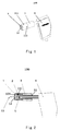
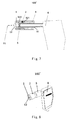
Fig. 6 shows schematically a perspective view of an optical probe according to another embodiment of the present invention, in which a second sleeve is located at a first detection position; -
Fig. 7 shows schematically a cross-sectional view of the optical probe shown inFig. 6 ; -
Fig. 8 shows schematically another perspective view of the optical probe shown inFig. 6 , in which the second sleeve is located at a second detection position; and -
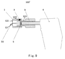
Fig. 9 shows schematically a cross-sectional view of the optical probe shown inFig. 8 . - Exemplary embodiments of the present invention will be described hereinafter in detail with reference to the attached drawings, wherein the like reference numerals refer to the like elements. The present invention may, however, be embodied in many different forms and should not be construed as being limited to the embodiment set forth herein; rather, these embodiments are provided so that the present invention will be thorough and complete, and will fully convey the concept of the disclosure to those skilled in the art.
-
Figs. 1-4 show schematically anoptical probe 100 according to an embodiment of the present invention. Theoptical probe 100 may include afirst sleeve 3, asecond sleeve 1 and apositioning member 2. Alens 5 is contained in thefirst sleeve 3. Thefirst sleeve 3 has alight transmission aperture 31 through which an exciting light enters thefirst sleeve 3. Thesecond sleeve 1 is slidably engaged with thefirst sleeve 3 and has adetection window 12, through which the exciting light having passed through thefirst sleeve 3 and focused by thelens 5 exits theoptical probe 100. Thesecond sleeve 1 is capable of moving with respect to thefirst sleeve 3 from a first detection position to a second detection position and from the second detection position to the first detection position. Thepositioning member 2 is configured to position thesecond sleeve 1 at the first detection position or the second detection position with respect to thefirst sleeve 3. - With a movement, such as rotation or slide, of the
second sleeve 1 with respect to thefirst sleeve 3, thesecond sleeve 1 may be switched between the extended first detection position (shown inFigs. 1-2 ) and the retracted second detection position (shown inFigs. 3-4 ). Positional relationships between thedetection window 12 of thesecond sleeve 1 and an optical device (for example. the lens 5) in thefirst sleeve 3 when thesecond sleeve 1 is in the first detection position are different from those when thesecond sleeve 1 is in the second detection position. For example, a distance between thedetection window 12 and afocus point 51 of thelens 5 on the side towards thedetection window 12 when thesecond sleeve 1 is at the first detection position is greater than a distance between thedetection window 12 and thefocus point 51 of thelens 5 on the side towards thedetection window 12 when thesecond sleeve 1 is at the second detection position. - In a practical field inspection, in order to operate conveniently, an
outer end face 121 of thesecond sleeve 1 may be pressed against an object to be inspected, so as to maintain a constant distance between the object and thelens 5 in thefirst sleeve 3 such that exciting light can be focused stably at a inspection point on the object to acquire a signal. If the object is a massive solid object, thedetection window 12 may be directly pressed against the object to perform inspection. In this case, it is desired that thefocal point 51 of the lens is located out of thesecond sleeve 1 and adjacent to theouter end face 121 of thesecond sleeve 1. Or, if the object is, for example, a gas, liquid, powders or gels hermetically contained in a vessel such as a glass bottle or a plastic bottle, thedetection window 12 may be pressed against an outer wall of the vessel allowing the exciting light to pass through the wall of the vessel and to be focused onto the object. In this case, it is desired that thefocal point 51 of the lens is located out of thesecond sleeve 1 and at a certain distance from theouter end face 121 of thesecond sleeve 1. Thus, as an example, the first detection position and the second detection position of thesecond sleeve 1 may be configured such that, at the first detection position, thefocal point 51 of thelens 5 on the side towards thedetection window 12 is located out of thesecond sleeve 1 and at a certain distance (for example 1-5 cm) from theouter end face 121 of thesecond sleeve 1 for inspecting an object contained in a vessel; at the second detection position, thefocal point 51 of thelens 5 on the side towards thedetection window 12 is located out of thesecond sleeve 1 and adjacent to theouter end face 121 of thesecond sleeve 1 for inspecting the massive solid object,. - In an example, the
first sleeve 3 and thesecond sleeve 1 may be engaged coaxially with each other. For example, the axis of thefirst sleeve 3 and the axis of thesecond sleeve 1 are in coincidence with the optical axis of thelens 5. This facilitates adjustment and calibration of the position of thefocal point 51 of thelens 5. As an example, thesecond sleeve 1 may be extended and retracted along the optical axis of thelens 5. However, it is not necessary. For example, the axis of thesecond sleeve 1 may be orientated at an angle relative to the optical axis of thelens 5, as long as it can ensure that the exciting light may be emitted correctly from thedetection window 12. - In an example, the positioning
member 2 may have a fixedportion 23 and aretractable portion 20. The fixedportion 23 may be fixed to thefirst sleeve 3 or thesecond sleeve 1.Fig. 5 shows an example of thepositioning member 2. In the example, theretractable portion 20 includes aball 21 and acompression spring 22. The fixedportion 23 may be, for example, a plug housing. The fixedportion 23 has a blind hole with an opening. Thecompression spring 22 is disposed at the bottom of the blind hole and theball 21 is disposed on thecompression spring 22. The diameter of the opening of the blind hole is smaller than the diameter of theball 21 to prevent theball 21 from escaping out of the blind hole. When being pressed inward from outside of the blind hole, theball 21 may compress thecompression spring 22 and thereby theupper ball 21 can retract further into the blind hole. Once the pressing action is removed, theball 21 may be pushed outward by thecompression spring 22 and pressed against the opening part of the blind hole to be positioned again at its unretracted position. Theball 21 may be made of metal, such as steel, or may be made of other materials having sufficient hardness, such as plastics. It should be noted that the above description with reference toFig. 5 only provides an example of thepositioning member 2. Instead, other forms of components in the art that can be fitted to the holes or grooves to position the sleeves may also be used in thepositioning member 2. - In an embodiment, as illustrated in
Figs. 1-4 , thesecond sleeve 1 is provided with afirst positioning hole 111 corresponding to the first detection position and asecond positioning hole 112 corresponding to the second detection position. The fixedportion 23 of thepositioning member 2 may be fixed to thefirst sleeve 3. When thesecond sleeve 1 is at the first detection position, theretractable portion 20 of thepositioning member 2 extends into thefirst positioning hole 111 to lock the position of thesecond sleeve 1, and when thesecond sleeve 1 is at the second detection position, theretractable portion 20 extends into thesecond positioning hole 112 to lock the position of thesecond sleeve 1. As an example, if thepositioning member 2 shown inFig. 5 is used, theball 21 will be pushed outward by the compression spring into thefirst positioning hole 111 when thesecond sleeve 1 is moved to the first detection position with respect to thefirst sleeve 3, such that thesecond sleeve 1 can be held stably at the first detection position; on the other hand, the inner wall of thesecond sleeve 1 will force theball 21 to retract into the fixedportion 23 when thesecond sleeve 1 is moved away from the first detection position. When thesecond sleeve 1 is moved to the second detection position, theball 21 will be pushed outward by thecompression spring 22 again into thesecond positioning hole 112, such that thesecond sleeve 1 can be held stably at the second detection position. - In an example, the
first sleeve 3 and thesecond sleeve 1 are threadedly engaged and are able to rotate with respect to each other through screw threads. In this circumstance, thefirst positioning hole 111 and thesecond positioning hole 112 are located along a same screw thread such that thesecond sleeve 1 can rotate along the same screw thread with respect to thefirst sleeve 3 to switch between the first detection and the second detection. - As an example, the
optical probe 100 may further include an opticalfiber coupling device 4 configured to direct a exciting light into thefirst sleeve 3 and receive light returned from thefirst sleeve 3. However, the present invention is not limited to this. Theoptical probe 100 according to an embodiment of the present invention may also include, for example, an optical device composed of separate optical elements, such as lenses, mirrors and prisms. The optical device may also be used to direct exciting light into thefirst sleeve 3 and receive light returned from thefirst sleeve 3. -
Figs. 6-9 show an optical probe 100' according to another embodiment of the present invention. Differences between the embodiment shown inFigs .6-9 and the embodiment shown inFigs. 1-4 mainly lie in the connection and positioning structure between thefirst sleeve 3 and thesecond sleeve 1. In particular, as shown inFigs. 6-9 , thefirst sleeve 3 is provided with a firstannular positioning groove 321 corresponding to the first detection position and a secondannular positioning groove 322 corresponding to the second detection position, and the fixedportion 23 of thepositioning member 2 is fixed to thesecond sleeve 1. When thesecond sleeve 1 is at the first detection position, theretractable portion 20 of thepositioning member 2 extends into the firstannular positioning groove 321 to lock the position of thesecond sleeve 1, and when thesecond sleeve 1 is at the second detection position, theretractable portion 20 extends into the secondannular positioning groove 322 to lock the position of thesecond sleeve 1. As an example, if thepositioning member 2 as shown inFig. 5 is used, theball 21 will be pushed outward by thecompression spring 22 into the firstannular positioning groove 321 when thesecond sleeve 1 is moved to the first detection position with respect to thefirst sleeve 3, such that thesecond sleeve 1 can be held stably at the first detection position; on the other hand, the wall of thesecond sleeve 1 will force theball 21 to retract into the fixedportion 23 when thesecond sleeve 1 is moved away from the first detection position. When thesecond sleeve 1 is moved to the second detection position, theball 21 will be pushed outward by thecompression spring 22 again into the secondannular positioning groove 322, such that thesecond sleeve 1 can be held stably at the second detection position. - In the embodiment shown in
Figs. 6-9 , thefirst sleeve 3 and thesecond sleeve 1 are engaged through polygonal fitting surfaces. That is to say, the fitting portion for engaging thefirst sleeve 3 and thesecond sleeve 1 with each other has a polygonal cross section, for example, a triangular cross section, a rectangular cross section, a pentagonal cross section, a hexagonal cross section or the like. With such polygonal fitting surfaces, thefirst sleeve 3 and thesecond sleeve 1 are not rotatable but axially slidable with respect to each other in contrast to the examples discussed above with references toFigs. 1-5 . Thus, thesecond sleeve 1 may be moved more conveniently with respect to thefirst sleeve 3. With thepositioning member 2 and the sliding engagement between thefirst sleeve 3 and thesecond sleeve 1, thesecond sleeve 1 can be switched between the first detection position and the second detection position by axially sliding relative to thefirst sleeve 3. For example, thesecond sleeve 1 can be actuated directly by a hand of the operator. In an example, the firstannular positioning groove 321 and the secondannular positioning groove 322 may be parallel to each other. It may allow thepositioning member 2 to position thesecond sleeve 1 in the same manner at any position on the circumference of thefirst sleeve 3, and thereby assembly and calibration process is simplified. - Other features in the embodiment shown in
Figs. 6-9 are the same as those in the previous embodiment shown inFigs. 1-4 . Thus, the specific explanations to these features will be omitted. - In the above embodiments, the
lens 5 may have a fixed focal length, because the change of position of thefocal point 51 of thelens 5 does not depends on the change of the focal length. Of course, thelens 5 may also have a variable focal length. - In the above embodiments, axial travel length of the
second sleeve 1 with respect to thefirst sleeve 3 maybe, for example, 0.5-10 cm, such as 1-5 cm. - It should be noted that, although the above embodiments of the present invention are described with reference to two detection positions, the
optical probes 100, 100' according to the embodiments of the present invention may also provide more detection positions to meet the requirements for various measurement applications. For example, a third detection position, a fourth detection position, and a fifth detection position may be provided between the first detection position and the second detection position. In such circumstances, a third positioning hole, a fourth positioning hole, and a fifth positioning hole, or a third annular positioning groove, a fourth annular positioning groove, and a fifth annular positioning groove may be provided correspondingly. - The optical probe according to the embodiments of the present invention may be applied in a Raman inspection, a florescence inspection or other various applications of optical inspection.
- Although the present invention has been explained with reference to the drawings, the embodiments shown in the drawings are only illustrative, instead of limiting the present invention.
- Although some embodiments of the general inventive concept are illustrated and explained, it would be appreciated by those skilled in the art that modifications and variations may be made in these embodiments without departing from the principles and spirit of the general inventive concept of the disclosure, the scope of which is defined in the appended claims and their equivalents.
Claims (10)
- An optical probe, comprising:a first sleeve in which a lens is contained, the first sleeve having a light transmission aperture from which a exciting light enters the first sleeve;a second sleeve movably engaged with the first sleeve and having a detection window from which the exciting light having passed through the first sleeve and focused by the lens exits the optical probe, the second sleeve being capable of moving with respect to the first sleeve from a first detection position to a second detection position or from the second detection position to the first detection position; anda positioning member configured to position the second sleeve at the first detection position or the second detection position with respect to the first sleeve.
- The optical probe according to claim 1, wherein a distance between the detection window and a focus point of the lens on the side towards the detection window when the second sleeve is at the first detection position is greater than a distance between the detection window and the focus point of the lens on the side towards the detection window when the second sleeve is at the second detection position.
- The optical probe according to claim 2, wherein when the second sleeve is at the second detection position, the focus point of the lens on the side towards the detection window is located out of the second sleeve and adjacent to an outer end face of the second sleeve.
- The optical probe according to any one of claims 1-3, wherein the positioning member has a fixed portion which is fixed to the first or the second sleeve and a retractable portion.
- The optical probe according to any one of claims 1-4, wherein the first sleeve and the second sleeve are coaxially engaged with each other.
- The optical probe according to any one of claims 1-3, wherein the second sleeve is provided with a first positioning hole corresponding to the first detection position and a second positioning hole corresponding to the second detection position, the positioning member having a fixed portion which is fixed to the first sleeve and a retractable portion, and wherein the retractable portion extends into the first positioning hole when the second sleeve is at the first detection position to fix the second sleeve, and the retractable portion extends into the second positioning hole when the second sleeve is at the second detection position to fix the second sleeve.
- The optical probe according to claim 6, wherein the first sleeve and the second sleeve are threadedly engaged with each other and are able to rotate with respect to each other along screw threads, the first positioning hole and the second positioning hole being located along a same screw thread.
- The optical probe according to any one of claims 1-3, wherein the first sleeve is provided with a first annular positioning groove corresponding to the first detection position and a second annular positioning groove corresponding to the second detection position, the positioning member having a fixed portion which is fixed to the second sleeve and a retractable portion, and wherein the retractable portion extends into the first annular positioning groove when the second sleeve is at the first detection position to fix the second sleeve, and the retractable portion extends into the second annular positioning groove when the second sleeve is at the second detection position to fix the second sleeve.
- The optical probe according to claim 8, the first sleeve and the second sleeve are engaged with each other through polygonal fitting surfaces, the first annular positioning groove and the second annular positioning groove being parallel to each other.
- The optical probe according to any one of claims 1-9, further comprising an optical fiber coupling device or an optical device configured to direct the exciting light into the first sleeve and receive the light back from the first sleeve, wherein the optical device is composed of separate optical elements.
Applications Claiming Priority (2)
| Application Number | Priority Date | Filing Date | Title |
|---|---|---|---|
| CN201310741550.4A CN104749103A (en) | 2013-12-27 | 2013-12-27 | Optical probe |
| PCT/CN2014/094954 WO2015096774A1 (en) | 2013-12-27 | 2014-12-25 | Optical probe |
Publications (2)
| Publication Number | Publication Date |
|---|---|
| EP3088864A1 true EP3088864A1 (en) | 2016-11-02 |
| EP3088864A4 EP3088864A4 (en) | 2017-08-23 |
Family
ID=53372308
Family Applications (1)
| Application Number | Title | Priority Date | Filing Date |
|---|---|---|---|
| EP14875689.3A Withdrawn EP3088864A4 (en) | 2013-12-27 | 2014-12-25 | Optical probe |
Country Status (5)
| Country | Link |
|---|---|
| US (1) | US9465189B2 (en) |
| EP (1) | EP3088864A4 (en) |
| CN (1) | CN104749103A (en) |
| DE (1) | DE102014226292A1 (en) |
| WO (1) | WO2015096774A1 (en) |
Families Citing this family (3)
| Publication number | Priority date | Publication date | Assignee | Title |
|---|---|---|---|---|
| CN110504616B (en) * | 2019-09-04 | 2024-07-19 | 江苏集萃激光智能装备有限公司 | Fiber laser alignment output device |
| JP2023510210A (en) * | 2020-01-03 | 2023-03-13 | トルネード スペクトラル システムズ インコーポレイテッド | Mechanical Mounting of Removable Tip Optics of Optical Spectroscopy Probes |
| CN117929279B (en) * | 2024-03-21 | 2024-06-04 | 南京诺源医疗器械有限公司 | Guiding device and guiding method for assisting laser real-time positioning and collecting Raman spectra |
Family Cites Families (18)
| Publication number | Priority date | Publication date | Assignee | Title |
|---|---|---|---|---|
| US4003059A (en) * | 1974-02-07 | 1977-01-11 | Canon Kabushiki Kaisha | Optical recorder having focus controlling means |
| US4428651A (en) * | 1981-12-17 | 1984-01-31 | Swift Instruments, Inc. | Click-stop focusing of binoculars |
| US5576529A (en) * | 1986-08-08 | 1996-11-19 | Norand Technology Corporation | Hand-held optically readable information set reader focus with operation over a range of distances |
| US5841121A (en) * | 1988-08-31 | 1998-11-24 | Norand Technology Corporation | Hand-held optically readable character set reader having automatic focus control for operation over a range of distances |
| JPH0769162B2 (en) * | 1990-04-23 | 1995-07-26 | 大日本スクリーン製造株式会社 | Automatic focusing device for optical inspection system |
| JP3260795B2 (en) * | 1992-02-14 | 2002-02-25 | キヤノン株式会社 | Injection optical device and automatic adjustment device thereof |
| US5931065A (en) * | 1997-05-19 | 1999-08-03 | Jackson; Roger Lee | Hand tool with axially repositionable shaft |
| DE60236975D1 (en) * | 2001-09-17 | 2010-08-19 | Lumination Llc | Interchangeable Lens point module |
| US6897951B2 (en) * | 2003-02-14 | 2005-05-24 | Raman Systems, Inc. | Probe assemblies for Raman spectroscopy |
| JP4796864B2 (en) * | 2006-02-27 | 2011-10-19 | Hoya株式会社 | Shading device |
| CN100596329C (en) * | 2006-06-25 | 2010-03-31 | 聚光科技(杭州)有限公司 | Replacement method and device for inner tube of in-situ photoelectric analysis system |
| JP5231162B2 (en) * | 2008-10-22 | 2013-07-10 | 株式会社 ニコンビジョン | Optical equipment |
| CN201775684U (en) * | 2010-08-17 | 2011-03-30 | 重庆海扶(Hifu)技术有限公司 | Double B-ultrasound probe positioning device |
| CN202522518U (en) * | 2012-03-23 | 2012-11-07 | 哈尔滨工业大学(威海) | Handheld Raman spectrometer focusing device |
| CN202600239U (en) * | 2012-05-31 | 2012-12-12 | 上海奥通激光技术有限公司 | Optical focusing fastening mechanism |
| CN203273438U (en) * | 2013-05-28 | 2013-11-06 | 广东凯西欧照明有限公司 | LED lamp bulb with adjustable light spot |
| CN103447688B (en) * | 2013-08-28 | 2015-09-16 | 广东大族粤铭激光科技股份有限公司 | Manual regulation formula laser cutting head subassembly |
| CN203643318U (en) * | 2013-12-27 | 2014-06-11 | 同方威视技术股份有限公司 | optical probe |
-
2013
- 2013-12-27 CN CN201310741550.4A patent/CN104749103A/en active Pending
-
2014
- 2014-12-17 DE DE102014226292.5A patent/DE102014226292A1/en not_active Withdrawn
- 2014-12-17 US US14/573,387 patent/US9465189B2/en not_active Expired - Fee Related
- 2014-12-25 WO PCT/CN2014/094954 patent/WO2015096774A1/en not_active Ceased
- 2014-12-25 EP EP14875689.3A patent/EP3088864A4/en not_active Withdrawn
Also Published As
| Publication number | Publication date |
|---|---|
| US20150185431A1 (en) | 2015-07-02 |
| WO2015096774A1 (en) | 2015-07-02 |
| DE102014226292A1 (en) | 2015-07-02 |
| EP3088864A4 (en) | 2017-08-23 |
| CN104749103A (en) | 2015-07-01 |
| US9465189B2 (en) | 2016-10-11 |
Similar Documents
| Publication | Publication Date | Title |
|---|---|---|
| US5051602A (en) | Optical system and method for sample analyzation | |
| CA2823481A1 (en) | A device for evaluation of fluids using electromagnetic energy | |
| US9465189B2 (en) | Optical probe | |
| US10598912B2 (en) | Objective optical system for ATR measurement | |
| CN110376700B (en) | Light path adjusting mechanism based on digital micromirror unit and adjusting method thereof | |
| CN102621123A (en) | Focusing device of handheld Raman spectrometer | |
| AU2016315424B2 (en) | Apparatus and method for performing a light-absorption measurement on a test sample and a compliance measurement on a reference sample | |
| US9869586B2 (en) | Sampling heads for handheld RAMAN spectroscopy devices | |
| CN208672903U (en) | A kind of auto-focusing metallographic microscope | |
| JP6421817B2 (en) | Surface property measuring device | |
| CN104990908B (en) | The confocal induced breakdown Raman spectrum imaging detection method of laser twin shaft and device | |
| CN203643318U (en) | optical probe | |
| CA3165895A1 (en) | Mechanical mount for removable front-end optics on an optical spectroscopy probe | |
| EP2997350B1 (en) | Turbidimeter | |
| US6762415B1 (en) | Vacuum chamber with recessed viewing tube and imaging device situated therein | |
| CN110261364B (en) | Handheld Raman spectrometer and detection method | |
| CN217210813U (en) | Testing device | |
| CN210571969U (en) | Raman spectrometer with multiple application scenes | |
| US20150146201A1 (en) | Optical probe with extended working distance | |
| CN105115960A (en) | Transmission-type prepositive optical path structure used for ICP spectrometer and having two-dimensional adjustable function | |
| CN210894072U (en) | Detection accessory capable of adjusting working distance of handheld Raman spectrometer | |
| CN205538712U (en) | Surface inspection device | |
| EP4206626A1 (en) | Capillary probe for handheld raman | |
| CN105510296A (en) | Portable fluorescence-disappearance Raman spectrum detection system | |
| CN111721749B (en) | Probe device for Raman detection |
Legal Events
| Date | Code | Title | Description |
|---|---|---|---|
| PUAI | Public reference made under article 153(3) epc to a published international application that has entered the european phase |
Free format text: ORIGINAL CODE: 0009012 |
|
| 17P | Request for examination filed |
Effective date: 20160715 |
|
| AK | Designated contracting states |
Kind code of ref document: A1 Designated state(s): AL AT BE BG CH CY CZ DE DK EE ES FI FR GB GR HR HU IE IS IT LI LT LU LV MC MK MT NL NO PL PT RO RS SE SI SK SM TR |
|
| AX | Request for extension of the european patent |
Extension state: BA ME |
|
| DAX | Request for extension of the european patent (deleted) | ||
| A4 | Supplementary search report drawn up and despatched |
Effective date: 20170721 |
|
| RIC1 | Information provided on ipc code assigned before grant |
Ipc: G01N 21/01 20060101AFI20170717BHEP Ipc: G01N 21/63 20060101ALI20170717BHEP |
|
| RIN1 | Information on inventor provided before grant (corrected) |
Inventor name: ZHAO, ZIRAN Inventor name: ZHANG, SHIXIN Inventor name: ZHANG, JIANHONG Inventor name: WANG, HONGQIU Inventor name: LIN, DONG Inventor name: YI, YUMIN Inventor name: HU, BIN |
|
| STAA | Information on the status of an ep patent application or granted ep patent |
Free format text: STATUS: EXAMINATION IS IN PROGRESS |
|
| 17Q | First examination report despatched |
Effective date: 20200917 |
|
| STAA | Information on the status of an ep patent application or granted ep patent |
Free format text: STATUS: THE APPLICATION IS DEEMED TO BE WITHDRAWN |
|
| 18D | Application deemed to be withdrawn |
Effective date: 20210128 |