EP3088731A1 - Transport system for transportation of a generator of a wind turbine and method for transportation of the generator - Google Patents
Transport system for transportation of a generator of a wind turbine and method for transportation of the generator Download PDFInfo
- Publication number
- EP3088731A1 EP3088731A1 EP15165843.2A EP15165843A EP3088731A1 EP 3088731 A1 EP3088731 A1 EP 3088731A1 EP 15165843 A EP15165843 A EP 15165843A EP 3088731 A1 EP3088731 A1 EP 3088731A1
- Authority
- EP
- European Patent Office
- Prior art keywords
- generator
- transport
- frame element
- transport frame
- transportation
- Prior art date
- Legal status (The legal status is an assumption and is not a legal conclusion. Google has not performed a legal analysis and makes no representation as to the accuracy of the status listed.)
- Granted
Links
Images


Classifications
-
- F—MECHANICAL ENGINEERING; LIGHTING; HEATING; WEAPONS; BLASTING
- F03—MACHINES OR ENGINES FOR LIQUIDS; WIND, SPRING, OR WEIGHT MOTORS; PRODUCING MECHANICAL POWER OR A REACTIVE PROPULSIVE THRUST, NOT OTHERWISE PROVIDED FOR
- F03D—WIND MOTORS
- F03D13/00—Assembly, mounting or commissioning of wind motors; Arrangements specially adapted for transporting wind motor components
- F03D13/40—Arrangements or methods specially adapted for transporting wind motor components
-
- B—PERFORMING OPERATIONS; TRANSPORTING
- B60—VEHICLES IN GENERAL
- B60P—VEHICLES ADAPTED FOR LOAD TRANSPORTATION OR TO TRANSPORT, TO CARRY, OR TO COMPRISE SPECIAL LOADS OR OBJECTS
- B60P3/00—Vehicles adapted to transport, to carry or to comprise special loads or objects
- B60P3/40—Vehicles adapted to transport, to carry or to comprise special loads or objects for carrying long loads, e.g. with separate wheeled load supporting elements
-
- F—MECHANICAL ENGINEERING; LIGHTING; HEATING; WEAPONS; BLASTING
- F05—INDEXING SCHEMES RELATING TO ENGINES OR PUMPS IN VARIOUS SUBCLASSES OF CLASSES F01-F04
- F05B—INDEXING SCHEME RELATING TO WIND, SPRING, WEIGHT, INERTIA OR LIKE MOTORS, TO MACHINES OR ENGINES FOR LIQUIDS COVERED BY SUBCLASSES F03B, F03D AND F03G
- F05B2220/00—Application
- F05B2220/70—Application in combination with
- F05B2220/706—Application in combination with an electrical generator
- F05B2220/7066—Application in combination with an electrical generator via a direct connection, i.e. a gearless transmission
-
- Y—GENERAL TAGGING OF NEW TECHNOLOGICAL DEVELOPMENTS; GENERAL TAGGING OF CROSS-SECTIONAL TECHNOLOGIES SPANNING OVER SEVERAL SECTIONS OF THE IPC; TECHNICAL SUBJECTS COVERED BY FORMER USPC CROSS-REFERENCE ART COLLECTIONS [XRACs] AND DIGESTS
- Y02—TECHNOLOGIES OR APPLICATIONS FOR MITIGATION OR ADAPTATION AGAINST CLIMATE CHANGE
- Y02E—REDUCTION OF GREENHOUSE GAS [GHG] EMISSIONS, RELATED TO ENERGY GENERATION, TRANSMISSION OR DISTRIBUTION
- Y02E10/00—Energy generation through renewable energy sources
- Y02E10/70—Wind energy
- Y02E10/72—Wind turbines with rotation axis in wind direction
Definitions
- the present invention refers to a transport system for transportation of a generator of a wind turbine and a method for transportation of the generator.
- a wind turbine comprises a generator for transferring kinetic energy of the wind into electricity.
- the generator which is driven by wind turbine blades is located in a nacelle of the wind turbine.
- the nacelle is mounted on a top of a tower of the wind turbine.
- a transport system with at least two transport wheel units is used. Between the transport wheel units a transport frame is arranged for carrying the generator during the transportation.
- the generator is fixed to the transport frame with the aid of lashing chains. These lashing chains may cause damage of the surface of the generators.
- such a transport system is not flexible enough in view of possible driving obstacles like hills or curves.
- a transport system for transportation of a generator of a wind turbine comprises at least one first transport wheel unit, at least one second transport wheel unit and at least one main transport frame element for carrying the generator during the transportation of the generator.
- the main transport frame element is arranged between the first transport wheel unit and the second transport wheel unit.
- the main transport frame element is connected to at least one tower clamp-set for a transportation of a tower segment of a tower of the wind turbine.
- the tower clamp-set is installed on top of at least one of the transport wheel units.
- the tower clamp-set is designed such that the tower segment can be lifted off a ground during the transportation of the tower segment.
- a method for transportation of a generator of a wind turbine by using the transport system is provided with following steps: a) attaching the generator to the main transport frame element, b) fixing of the generator to the main transport frame element and c) transporting the transport frame with the generator.
- a direct drive generator of a wind turbine is used as a generator.
- the direct drive generator can be transported with the aid of the transport system.
- the main transport frame element is a carrier frame in which the generator can be arranged.
- the main transport frame element is connected to both transport wheel units.
- the transport wheel units are multi wheel trailers.
- the tower clamp-set is installed on the respective top of both wheel units.
- Each of the transport wheel units comprise at least one lifting means for the lifting of the tower segment during its transportation. These lifting means are components of the clamp-set.
- the transport frame is fixed to both transport wheel units. This is carried out with the aid of beams with which the transport frame is located between the transport wheel units.
- the tower clamp-set is a standard tower clamp-set.
- the standard tower clamp-set is not adapted to specific components of the wind turbine. It is used for the transportation of different components of the wind turbine.
- the main transport frame element comprises a bottom transport frame element for supporting the generator.
- the bottom transport frame element is a component of the complete transport frame.
- the generator can be fixed to the bottom transport frame with the aid at least one fixing element which is selected from the group consisting of bolts and twist locks.
- Alternative fixing elements are possible, too.
- the main transport frame element comprises at least one removable top transport frame element for stabilizing the main transport frame element.
- the top transport frame element is a component of the complete transport frame, too.
- the top transport frame element comprises at least one beam and/or at least one compression bar.
- the use of the top transport element is advantageous due to the heavy load which is connected to a generator. Moreover, due to the possibility of removing this top transport frame element, the generator can easily be arranged at the bottom frame transport element. In addition, the generator which is located on the bottom transport frame element is easily accessible.
- the top transport frame element comprises proper components.
- the top transport frame element comprises at least one component which is selected from the group consisting of beam and compression bar.
- the number of these components is limited. For instance, just two beams are used.
- the aid of the compression bars it is possible to fix the generator at the bottom transport frame element with the aid of pressure. The generator is pressed against the bottom transport frame. This can support the above mentioned fixing elements.
- the removable top transport frame element comprises at least one stiffening element for stiffening the top transport frame element.
- the main transport frame element comprises at least one end transport frame element for enhancing a fixation of the generator to the main transport frame element.
- the end transport frame is an additional component of the complete transport frame.
- the end transport frame can be solidly fixed at the main transport frame element.
- the end transport frame element is detachably (removable) connected to the main transport frame element. This enhances a flexibility of the transport system: Different generators can be transported.
- the generator With the aid of the end transport frame the generator can be fixed during the transportation of the generator. It is decisive that it is not possible for the generator to move during the transportation. This is reached with the aid of the end frame.
- the transport system can be attached to a truck.
- the truck is a standard truck.
- the wheel units can be removable attached to the truck.
- Base is a transport system 1 for transporting a generator 201 of a wind turbine 2. 10.
- the transport system can be attached to a truck 4.
- the truck is a standard truck.
- the transport system 1 comprises a first transport wheel unit 11, a second transport wheel unit 12 and a main transport frame element 13 for carrying the generator 201 during a transportation of the generator 201.
- the main transport frame element 13 is a main carrier transport frame element in which the generator 201 of the wind turbine 2 can be arranged for its transportation.
- the transport wheel units 11 and 12 are multi wheel units.
- the main transport frame element 13 is arranged between the first transport wheel unit 11 and the second transport wheel unit 12.
- the main transport frame element 13 is connected to a tower clamp set 10 for a transportation of a tower segment 211 of a tower 20 of the wind turbine 2.
- the clamp-set 10 is a standard tower clamp-set 101.
- the standard clamp-set 101 is installed on top 111 of the transport wheel unit 11 and on top 121 of the transport wheel unit 12.
- the standard clamp-set 101 is designed such that the tower segment 211 can be lifted off a ground 3 during the transportation of the tower segment 211.
- the main transport frame element 13 comprises a bottom transport frame element 131 for supporting the generator 211.
- the bottom transport frame element 131 is a bottom carrier transport frame element.
- the generator 211 is fixed to the bottom transport frame 131 with the aid of a number of fixing element 1311.
- the fixing elements 1311 are bolts and/or twist locks.
- the main transport frame element 13 comprises at least one detachable (removable) top transport frame element 132 for stabilizing the main transport frame element 13.
- the detachable top transport frame element 132 is a detachable top carrier frame element which is detachably connected to the main transport frame element 13. It comprises beams 1322 and compression bars 1323 with which the generator is pressed towards the bottom transport frame element 131. By this, the generator is fixed at least during the transportation of the generator.
- the removable top transport frame element 132 comprises at least one stiffening element 1321 for stiffening the top transport frame element 132.
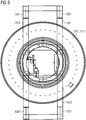
- Figure 3 shows four stiffening elements 1321 for stiffening the beams 1322 of the top transport frame element 132.
- the stiffening elements 1331 are located at the ends of the transport frame element 132.
- the main transport frame element 13 comprises two end transport frame elements 133 for enhancing a fixation of the generator 211 to the main transport frame element 13. These end transport frame element 133 are detachably connected to the main transport frame element 13. Alternatively, theses end transport frame elements are fastened to the main transport frame element 13.
- a transportation of a generator 211 of a wind turbine 2 with following steps is carried out: a) Attaching the generator 211 to the main transport frame element 13, b) fixing of the generator 211 to the main transport frame element 13 and c) transporting the transport frame 13 with the generator 211.
- a direct drive generator 2111 of a wind turbine 2 is transported.
- the generator is transported to a site where a wind turbine is installed or to a harbor or to a railway station for further transportation of the generator 211.
Landscapes
- Engineering & Computer Science (AREA)
- Mechanical Engineering (AREA)
- Life Sciences & Earth Sciences (AREA)
- Sustainable Development (AREA)
- Sustainable Energy (AREA)
- Chemical & Material Sciences (AREA)
- Combustion & Propulsion (AREA)
- General Engineering & Computer Science (AREA)
- Health & Medical Sciences (AREA)
- Public Health (AREA)
- Transportation (AREA)
- Wind Motors (AREA)
Abstract
Description
- The present invention refers to a transport system for transportation of a generator of a wind turbine and a method for transportation of the generator.
- A wind turbine comprises a generator for transferring kinetic energy of the wind into electricity. The generator which is driven by wind turbine blades is located in a nacelle of the wind turbine. The nacelle is mounted on a top of a tower of the wind turbine.
- For wind turbines, large generators are used. It is difficult to transport such large generators, especially large direct drive generators, on a road.
- For the transportation of the generator of the wind turbine on a road, a transport system with at least two transport wheel units is used. Between the transport wheel units a transport frame is arranged for carrying the generator during the transportation.
- The generator is fixed to the transport frame with the aid of lashing chains. These lashing chains may cause damage of the surface of the generators. In addition, such a transport system is not flexible enough in view of possible driving obstacles like hills or curves.
- It is an objective of the invention to provide an easy solution for transporting of heavy generators of a wind turbine without lashing chains.
- This objective is achieved by the invention specified in the claims.
- Concerning the invention, a transport system for transportation of a generator of a wind turbine is provided. The transport system comprises at least one first transport wheel unit, at least one second transport wheel unit and at least one main transport frame element for carrying the generator during the transportation of the generator. The main transport frame element is arranged between the first transport wheel unit and the second transport wheel unit. The main transport frame element is connected to at least one tower clamp-set for a transportation of a tower segment of a tower of the wind turbine. The tower clamp-set is installed on top of at least one of the transport wheel units. The tower clamp-set is designed such that the tower segment can be lifted off a ground during the transportation of the tower segment.
- In addition to the transport system, a method for transportation of a generator of a wind turbine by using the transport system is provided with following steps: a) attaching the generator to the main transport frame element, b) fixing of the generator to the main transport frame element and c) transporting the transport frame with the generator. Especially, a direct drive generator of a wind turbine is used as a generator. The direct drive generator can be transported with the aid of the transport system.
- The main transport frame element is a carrier frame in which the generator can be arranged. The main transport frame element is connected to both transport wheel units. For instance, the transport wheel units are multi wheel trailers. Preferably, the tower clamp-set is installed on the respective top of both wheel units. Each of the transport wheel units comprise at least one lifting means for the lifting of the tower segment during its transportation. These lifting means are components of the clamp-set. The transport frame is fixed to both transport wheel units. This is carried out with the aid of beams with which the transport frame is located between the transport wheel units.
- With this solution it is not necessary to use a specific transport system for generators of a wind turbine. A transport system for other components of a wind turbine, namely for tower segments of the tower of wind turbine is used. Core of this transport system is the clamp-set with which the lifting off the ground of the transported component during its transportation is possible.
- More preferably, the tower clamp-set is a standard tower clamp-set. The standard tower clamp-set is not adapted to specific components of the wind turbine. It is used for the transportation of different components of the wind turbine.
- In a preferred embodiment, the main transport frame element comprises a bottom transport frame element for supporting the generator. The bottom transport frame element is a component of the complete transport frame.
- It is advantageous to fasten the generator during the transportation of the generator. This can be realized by suitable fastening components. Therefore, in a preferred embodiment, the generator can be fixed to the bottom transport frame with the aid at least one fixing element which is selected from the group consisting of bolts and twist locks. Alternative fixing elements are possible, too.
- Preferably, the main transport frame element comprises at least one removable top transport frame element for stabilizing the main transport frame element. The top transport frame element is a component of the complete transport frame, too. The top transport frame element comprises at least one beam and/or at least one compression bar. The use of the top transport element is advantageous due to the heavy load which is connected to a generator. Moreover, due to the possibility of removing this top transport frame element, the generator can easily be arranged at the bottom frame transport element. In addition, the generator which is located on the bottom transport frame element is easily accessible.
- The top transport frame element comprises proper components. In a preferred embodiment, the top transport frame element comprises at least one component which is selected from the group consisting of beam and compression bar. In order to reduce the total weight of the transports system, the number of these components is limited. For instance, just two beams are used. With the aid of the compression bars it is possible to fix the generator at the bottom transport frame element with the aid of pressure. The generator is pressed against the bottom transport frame. This can support the above mentioned fixing elements.
- In order to enhance the reliability and security of the transport system it is meaningful to strengthen the top transport frame element. Therefore, in a preferred embodiment, the removable top transport frame element comprises at least one stiffening element for stiffening the top transport frame element.
- For further enhancing the reliability and security of the transport system, the main transport frame element comprises at least one end transport frame element for enhancing a fixation of the generator to the main transport frame element. The end transport frame is an additional component of the complete transport frame. Thereby, the end transport frame can be solidly fixed at the main transport frame element. Preferably, the end transport frame element is detachably (removable) connected to the main transport frame element. This enhances a flexibility of the transport system: Different generators can be transported.
- With the aid of the end transport frame the generator can be fixed during the transportation of the generator. It is decisive that it is not possible for the generator to move during the transportation. This is reached with the aid of the end frame.
- Preferably, the transport system can be attached to a truck. The truck is a standard truck. The wheel units (trailers) can be removable attached to the truck.
- With the invention following specific advantages are achieved:
- With the transport system a secure transportation of heavy generators, especially direct drive generators is possible.
- Lashing chains which could violate or destroy a surface of the generator are not necessary.
- The use of standard clamp-sets for the transportation of wind power elements is possible. No specific adaption of the transport system for a heavy generator of a wind turbine is necessary.
- The transport system is flexible: Different generators with different sizes and different weight can be transported.
- The base of the transport system is a linked trailer system. This has the advantage that curves or hilltops of a road can easily be past.
-
-
Figure 1 shows a transport system in a side-view. -
Figure 2 shows a section offigure 1 . -
Figure 3 shows a section of a transport system with the generator in a top view. -
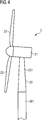
Figure 4 shows a wind turbine. - Base is a transport system 1 for transporting a
generator 201 of awind turbine 2. 10. The transport system can be attached to a truck 4. The truck is a standard truck. - The transport system 1 comprises a first
transport wheel unit 11, a secondtransport wheel unit 12 and a maintransport frame element 13 for carrying thegenerator 201 during a transportation of thegenerator 201. The maintransport frame element 13 is a main carrier transport frame element in which thegenerator 201 of thewind turbine 2 can be arranged for its transportation. Thetransport wheel units - The main
transport frame element 13 is arranged between the firsttransport wheel unit 11 and the secondtransport wheel unit 12. The maintransport frame element 13 is connected to a tower clamp set 10 for a transportation of a tower segment 211 of atower 20 of thewind turbine 2. The clamp-set 10 is a standard tower clamp-set 101. - The standard clamp-set 101 is installed on
top 111 of thetransport wheel unit 11 and ontop 121 of thetransport wheel unit 12. The standard clamp-set 101 is designed such that the tower segment 211 can be lifted off aground 3 during the transportation of the tower segment 211. - The main
transport frame element 13 comprises a bottomtransport frame element 131 for supporting the generator 211. The bottomtransport frame element 131 is a bottom carrier transport frame element. During the transportation, the generator 211 is fixed to thebottom transport frame 131 with the aid of a number of fixingelement 1311. The fixingelements 1311 are bolts and/or twist locks. - The main
transport frame element 13 comprises at least one detachable (removable) toptransport frame element 132 for stabilizing the maintransport frame element 13. The detachable toptransport frame element 132 is a detachable top carrier frame element which is detachably connected to the maintransport frame element 13. It comprisesbeams 1322 andcompression bars 1323 with which the generator is pressed towards the bottomtransport frame element 131. By this, the generator is fixed at least during the transportation of the generator. - Additionally, the removable top
transport frame element 132 comprises at least onestiffening element 1321 for stiffening the toptransport frame element 132.Figure 3 shows fourstiffening elements 1321 for stiffening thebeams 1322 of the toptransport frame element 132. The stiffening elements 1331 are located at the ends of thetransport frame element 132. - Moreover, the main
transport frame element 13 comprises two endtransport frame elements 133 for enhancing a fixation of the generator 211 to the maintransport frame element 13. These endtransport frame element 133 are detachably connected to the maintransport frame element 13. Alternatively, theses end transport frame elements are fastened to the maintransport frame element 13. - By using the described transport system 1 a transportation of a generator 211 of a
wind turbine 2 with following steps is carried out: a) Attaching the generator 211 to the maintransport frame element 13, b) fixing of the generator 211 to the maintransport frame element 13 and c) transporting thetransport frame 13 with the generator 211. Thereby, a direct drive generator 2111 of awind turbine 2 is transported. With the aid of the transport system, the generator is transported to a site where a wind turbine is installed or to a harbor or to a railway station for further transportation of the generator 211.
Claims (12)
- Transport system (1) for transportation of a generator (211) of a wind turbine (2), the transport system (1) comprising:- at least one first transport wheel unit (11);- at least one second transport wheel unit (12); and- at least one main transport frame element (13) for carrying the generator (211) during the transportation of the generator (211);wherein- the main transport frame element (13) is arranged between the first transport wheel unit (11) and the second transport wheel unit (12);- the main transport frame element (13) is connected to at least one tower clamp-set (10) for a transportation of a tower segment (211) of a tower (20) of the wind turbine (2);- the tower clamp-set (10) is installed on top (111, 121) of at least one of the transport wheel units (11, 12);- the tower clamp-set (10) is designed such that the tower segment (211) can be lifted off a ground (3) during the transportation of the tower segment (211).
- Transport system according to claim 1, wherein the tower clamp-set (10) is a standard tower clamp-set (101).
- Transport system according to claim 1 or 2, wherein the main transport frame element (13) comprises a bottom transport frame element (131) for supporting the generator (211).
- Transport system according to claims 3, wherein the generator (211) can be fixed to the bottom transport frame (131) with the aid at least one fixing element (1311) which is selected from the group consisting of bolts and twist locks.
- Transport system according to one of the claims 1 to 4, wherein the main transport frame element (13) comprises at least one removable top transport frame element (132) for stabilizing the main transport frame element (13).
- Transport system according to claim 5, wherein the top transport frame element (132) comprises at least one component which is selected from the group consisting of beam (1322) and compression bar (1323).
- Transport system according to claim 5 or 6, wherein the removable top transport frame element (132) comprises at least one stiffening element (1321) for stiffening the top transport frame element (132).
- Transport system according to one of the claims 1 to 7, wherein the main transport frame element (13) comprises at least one end transport frame element (133) for enhancing a fixation of the generator (211) to the main transport frame element (13).
- Transport system according to claim 8, wherein the end transport frame element (133) is detachably connected to the main transport frame element (13).
- Transport system according to one of the claims 1 to 9 which can be attached to a truck (4).
- Method for transportation of a generator (211) of a wind turbine (2) by using the transport system (1) according to one of the claims 1 to 10, with the steps:a) Attaching the generator (211) to the main transport frame element (13);b) Fixing of the generator (211) to the main transport frame element (13); andc) Transporting the transport frame (13) with the generator (211).
- Method according to claim 11, wherein a direct drive generator (2111) of a wind turbine (2) is used as the generator (2).
Priority Applications (1)
| Application Number | Priority Date | Filing Date | Title |
|---|---|---|---|
| EP15165843.2A EP3088731B1 (en) | 2015-04-30 | 2015-04-30 | Transport system for transportation of a generator of a wind turbine and method for transportation of the generator |
Applications Claiming Priority (1)
| Application Number | Priority Date | Filing Date | Title |
|---|---|---|---|
| EP15165843.2A EP3088731B1 (en) | 2015-04-30 | 2015-04-30 | Transport system for transportation of a generator of a wind turbine and method for transportation of the generator |
Publications (2)
| Publication Number | Publication Date |
|---|---|
| EP3088731A1 true EP3088731A1 (en) | 2016-11-02 |
| EP3088731B1 EP3088731B1 (en) | 2019-11-06 |
Family
ID=53039310
Family Applications (1)
| Application Number | Title | Priority Date | Filing Date |
|---|---|---|---|
| EP15165843.2A Active EP3088731B1 (en) | 2015-04-30 | 2015-04-30 | Transport system for transportation of a generator of a wind turbine and method for transportation of the generator |
Country Status (1)
| Country | Link |
|---|---|
| EP (1) | EP3088731B1 (en) |
Cited By (2)
| Publication number | Priority date | Publication date | Assignee | Title |
|---|---|---|---|---|
| US20210066917A1 (en) * | 2019-08-30 | 2021-03-04 | Smart Wires Inc. | Deployment of Power Flow Control Systems |
| CN116557220A (en) * | 2023-06-07 | 2023-08-08 | 远大可建科技有限公司 | Main machine transportation structure and method of wind driven generator |
Families Citing this family (1)
| Publication number | Priority date | Publication date | Assignee | Title |
|---|---|---|---|---|
| CN112696323A (en) * | 2020-12-30 | 2021-04-23 | 三一重能股份有限公司 | Wheel hub carrying assembly and wheel hub carrying system |
Citations (5)
| Publication number | Priority date | Publication date | Assignee | Title |
|---|---|---|---|---|
| JP2002059776A (en) * | 2000-08-17 | 2002-02-26 | Nippon Express Co Ltd | Transporting device for cylindrical structured tower for wind power generator |
| EP1336755A1 (en) * | 2002-02-19 | 2003-08-20 | Vestas Wind Systems A/S | Method of transportation of a wind turbine nacelle and use thereof |
| WO2004041589A1 (en) * | 2002-10-30 | 2004-05-21 | Koninklijke Nooteboom Trailers B.V. | Method and device for supporting a self-supporting load an undercarriages |
| DE102012002755A1 (en) * | 2012-02-11 | 2013-08-14 | Ge Wind Energy Gmbh | Method for handling tower segments for a tower and apparatus for handling tower segments |
| FR3006958A1 (en) * | 2013-06-18 | 2014-12-19 | Hel Lev Sa | LOAD TRANSPORT EQUIPMENT FOR ACCIDENT ENVIRONMENT |
-
2015
- 2015-04-30 EP EP15165843.2A patent/EP3088731B1/en active Active
Patent Citations (5)
| Publication number | Priority date | Publication date | Assignee | Title |
|---|---|---|---|---|
| JP2002059776A (en) * | 2000-08-17 | 2002-02-26 | Nippon Express Co Ltd | Transporting device for cylindrical structured tower for wind power generator |
| EP1336755A1 (en) * | 2002-02-19 | 2003-08-20 | Vestas Wind Systems A/S | Method of transportation of a wind turbine nacelle and use thereof |
| WO2004041589A1 (en) * | 2002-10-30 | 2004-05-21 | Koninklijke Nooteboom Trailers B.V. | Method and device for supporting a self-supporting load an undercarriages |
| DE102012002755A1 (en) * | 2012-02-11 | 2013-08-14 | Ge Wind Energy Gmbh | Method for handling tower segments for a tower and apparatus for handling tower segments |
| FR3006958A1 (en) * | 2013-06-18 | 2014-12-19 | Hel Lev Sa | LOAD TRANSPORT EQUIPMENT FOR ACCIDENT ENVIRONMENT |
Cited By (3)
| Publication number | Priority date | Publication date | Assignee | Title |
|---|---|---|---|---|
| US20210066917A1 (en) * | 2019-08-30 | 2021-03-04 | Smart Wires Inc. | Deployment of Power Flow Control Systems |
| US11807149B2 (en) * | 2019-08-30 | 2023-11-07 | Smart Wires Inc. | Deployment of power flow control systems |
| CN116557220A (en) * | 2023-06-07 | 2023-08-08 | 远大可建科技有限公司 | Main machine transportation structure and method of wind driven generator |
Also Published As
| Publication number | Publication date |
|---|---|
| EP3088731B1 (en) | 2019-11-06 |
Similar Documents
| Publication | Publication Date | Title |
|---|---|---|
| DK1476658T4 (en) | NACLE AND PROCEDURE FOR LOADING A WINDMILL ANCLE, INCLUDING A NAV OF A VEHICLE ARRANGEMENT | |
| EP1997681B1 (en) | Method and apparatus for containing, storing and/or transporting curved wind turbine rotor blades | |
| US20150369209A1 (en) | Rotor blade transportation system | |
| US8342491B2 (en) | Transport system for transportation of a spar | |
| EP2487363A1 (en) | Lifting system and method for lifting rotor blades of wind turbines | |
| EP1644271B1 (en) | Transporting and storing curved wind turbine blades | |
| DK2003333T3 (en) | Method for mounting at least two components of a wind turbine and using a handling device | |
| CN103403344B (en) | By the wind turbine blade method of operating without hoist mode of turbine hub | |
| DK2456973T3 (en) | PROCEDURE AND DEVICE FOR TRANSPORTING AND FITTING WINDOWS | |
| US10066606B2 (en) | Stacking wind turbine blades for sea transport | |
| EP2327655B1 (en) | Arrangement for the transport of wind turbine components | |
| EP2093417B1 (en) | Preassembled wind power plant tower section and method of transporting a tower section of a wind power plant | |
| EP3088731B1 (en) | Transport system for transportation of a generator of a wind turbine and method for transportation of the generator | |
| CA2654279A1 (en) | A handling system for a wind turbine nacelle, methods for transport and vertical displacement of a wind turbine nacelle and a use of a handling system | |
| CN102234084B (en) | Positioning bulk loads is in transport, the method for storage position, trailer and/or truck | |
| US20140248112A1 (en) | Two or three wind turbine blades as one unit | |
| CN101850874A (en) | Transporting system used for transporting wing beams | |
| RU2571042C2 (en) | System for transportation of bulky objects | |
| ES2884850T3 (en) | Method to produce a wind turbine, a nacelle structure and a wind turbine | |
| CN103696914A (en) | Equipment for marine transport wind generator | |
| EP2497686A1 (en) | A transportation method for a wind turbine blade | |
| CN202753951U (en) | Auxiliary inclined shaft construction platform car | |
| CN105365652A (en) | Heavy load concave bridge type transport equipment | |
| RU95101550A (en) | Mobile wind-driven power plant and method of mounting such plant | |
| RU2818434C1 (en) | Modular mobile ropeway |
Legal Events
| Date | Code | Title | Description |
|---|---|---|---|
| PUAI | Public reference made under article 153(3) epc to a published international application that has entered the european phase |
Free format text: ORIGINAL CODE: 0009012 |
|
| AK | Designated contracting states |
Kind code of ref document: A1 Designated state(s): AL AT BE BG CH CY CZ DE DK EE ES FI FR GB GR HR HU IE IS IT LI LT LU LV MC MK MT NL NO PL PT RO RS SE SI SK SM TR |
|
| AX | Request for extension of the european patent |
Extension state: BA ME |
|
| 17P | Request for examination filed |
Effective date: 20170502 |
|
| RBV | Designated contracting states (corrected) |
Designated state(s): AL AT BE BG CH CY CZ DE DK EE ES FI FR GB GR HR HU IE IS IT LI LT LU LV MC MK MT NL NO PL PT RO RS SE SI SK SM TR |
|
| STAA | Information on the status of an ep patent application or granted ep patent |
Free format text: STATUS: REQUEST FOR EXAMINATION WAS MADE |
|
| RAP1 | Party data changed (applicant data changed or rights of an application transferred) |
Owner name: SIEMENS AKTIENGESELLSCHAFT |
|
| RAP1 | Party data changed (applicant data changed or rights of an application transferred) |
Owner name: SIEMENS GAMESA RENEWABLE ENERGY A/S |
|
| GRAP | Despatch of communication of intention to grant a patent |
Free format text: ORIGINAL CODE: EPIDOSNIGR1 |
|
| STAA | Information on the status of an ep patent application or granted ep patent |
Free format text: STATUS: GRANT OF PATENT IS INTENDED |
|
| INTG | Intention to grant announced |
Effective date: 20190604 |
|
| GRAS | Grant fee paid |
Free format text: ORIGINAL CODE: EPIDOSNIGR3 |
|
| GRAA | (expected) grant |
Free format text: ORIGINAL CODE: 0009210 |
|
| STAA | Information on the status of an ep patent application or granted ep patent |
Free format text: STATUS: THE PATENT HAS BEEN GRANTED |
|
| AK | Designated contracting states |
Kind code of ref document: B1 Designated state(s): AL AT BE BG CH CY CZ DE DK EE ES FI FR GB GR HR HU IE IS IT LI LT LU LV MC MK MT NL NO PL PT RO RS SE SI SK SM TR |
|
| REG | Reference to a national code |
Ref country code: GB Ref legal event code: FG4D |
|
| REG | Reference to a national code |
Ref country code: CH Ref legal event code: EP Ref country code: AT Ref legal event code: REF Ref document number: 1199035 Country of ref document: AT Kind code of ref document: T Effective date: 20191115 |
|
| REG | Reference to a national code |
Ref country code: DE Ref legal event code: R096 Ref document number: 602015040953 Country of ref document: DE |
|
| REG | Reference to a national code |
Ref country code: IE Ref legal event code: FG4D |
|
| REG | Reference to a national code |
Ref country code: NL Ref legal event code: MP Effective date: 20191106 |
|
| REG | Reference to a national code |
Ref country code: LT Ref legal event code: MG4D |
|
| PG25 | Lapsed in a contracting state [announced via postgrant information from national office to epo] |
Ref country code: SE Free format text: LAPSE BECAUSE OF FAILURE TO SUBMIT A TRANSLATION OF THE DESCRIPTION OR TO PAY THE FEE WITHIN THE PRESCRIBED TIME-LIMIT Effective date: 20191106 Ref country code: LV Free format text: LAPSE BECAUSE OF FAILURE TO SUBMIT A TRANSLATION OF THE DESCRIPTION OR TO PAY THE FEE WITHIN THE PRESCRIBED TIME-LIMIT Effective date: 20191106 Ref country code: NL Free format text: LAPSE BECAUSE OF FAILURE TO SUBMIT A TRANSLATION OF THE DESCRIPTION OR TO PAY THE FEE WITHIN THE PRESCRIBED TIME-LIMIT Effective date: 20191106 Ref country code: NO Free format text: LAPSE BECAUSE OF FAILURE TO SUBMIT A TRANSLATION OF THE DESCRIPTION OR TO PAY THE FEE WITHIN THE PRESCRIBED TIME-LIMIT Effective date: 20200206 Ref country code: GR Free format text: LAPSE BECAUSE OF FAILURE TO SUBMIT A TRANSLATION OF THE DESCRIPTION OR TO PAY THE FEE WITHIN THE PRESCRIBED TIME-LIMIT Effective date: 20200207 Ref country code: PT Free format text: LAPSE BECAUSE OF FAILURE TO SUBMIT A TRANSLATION OF THE DESCRIPTION OR TO PAY THE FEE WITHIN THE PRESCRIBED TIME-LIMIT Effective date: 20200306 Ref country code: LT Free format text: LAPSE BECAUSE OF FAILURE TO SUBMIT A TRANSLATION OF THE DESCRIPTION OR TO PAY THE FEE WITHIN THE PRESCRIBED TIME-LIMIT Effective date: 20191106 Ref country code: PL Free format text: LAPSE BECAUSE OF FAILURE TO SUBMIT A TRANSLATION OF THE DESCRIPTION OR TO PAY THE FEE WITHIN THE PRESCRIBED TIME-LIMIT Effective date: 20191106 Ref country code: FI Free format text: LAPSE BECAUSE OF FAILURE TO SUBMIT A TRANSLATION OF THE DESCRIPTION OR TO PAY THE FEE WITHIN THE PRESCRIBED TIME-LIMIT Effective date: 20191106 Ref country code: BG Free format text: LAPSE BECAUSE OF FAILURE TO SUBMIT A TRANSLATION OF THE DESCRIPTION OR TO PAY THE FEE WITHIN THE PRESCRIBED TIME-LIMIT Effective date: 20200206 |
|
| PG25 | Lapsed in a contracting state [announced via postgrant information from national office to epo] |
Ref country code: HR Free format text: LAPSE BECAUSE OF FAILURE TO SUBMIT A TRANSLATION OF THE DESCRIPTION OR TO PAY THE FEE WITHIN THE PRESCRIBED TIME-LIMIT Effective date: 20191106 Ref country code: RS Free format text: LAPSE BECAUSE OF FAILURE TO SUBMIT A TRANSLATION OF THE DESCRIPTION OR TO PAY THE FEE WITHIN THE PRESCRIBED TIME-LIMIT Effective date: 20191106 Ref country code: IS Free format text: LAPSE BECAUSE OF FAILURE TO SUBMIT A TRANSLATION OF THE DESCRIPTION OR TO PAY THE FEE WITHIN THE PRESCRIBED TIME-LIMIT Effective date: 20200306 |
|
| PG25 | Lapsed in a contracting state [announced via postgrant information from national office to epo] |
Ref country code: AL Free format text: LAPSE BECAUSE OF FAILURE TO SUBMIT A TRANSLATION OF THE DESCRIPTION OR TO PAY THE FEE WITHIN THE PRESCRIBED TIME-LIMIT Effective date: 20191106 |
|
| PG25 | Lapsed in a contracting state [announced via postgrant information from national office to epo] |
Ref country code: CZ Free format text: LAPSE BECAUSE OF FAILURE TO SUBMIT A TRANSLATION OF THE DESCRIPTION OR TO PAY THE FEE WITHIN THE PRESCRIBED TIME-LIMIT Effective date: 20191106 Ref country code: RO Free format text: LAPSE BECAUSE OF FAILURE TO SUBMIT A TRANSLATION OF THE DESCRIPTION OR TO PAY THE FEE WITHIN THE PRESCRIBED TIME-LIMIT Effective date: 20191106 Ref country code: DK Free format text: LAPSE BECAUSE OF FAILURE TO SUBMIT A TRANSLATION OF THE DESCRIPTION OR TO PAY THE FEE WITHIN THE PRESCRIBED TIME-LIMIT Effective date: 20191106 Ref country code: EE Free format text: LAPSE BECAUSE OF FAILURE TO SUBMIT A TRANSLATION OF THE DESCRIPTION OR TO PAY THE FEE WITHIN THE PRESCRIBED TIME-LIMIT Effective date: 20191106 Ref country code: ES Free format text: LAPSE BECAUSE OF FAILURE TO SUBMIT A TRANSLATION OF THE DESCRIPTION OR TO PAY THE FEE WITHIN THE PRESCRIBED TIME-LIMIT Effective date: 20191106 |
|
| REG | Reference to a national code |
Ref country code: DE Ref legal event code: R097 Ref document number: 602015040953 Country of ref document: DE |
|
| REG | Reference to a national code |
Ref country code: AT Ref legal event code: MK05 Ref document number: 1199035 Country of ref document: AT Kind code of ref document: T Effective date: 20191106 |
|
| PG25 | Lapsed in a contracting state [announced via postgrant information from national office to epo] |
Ref country code: SK Free format text: LAPSE BECAUSE OF FAILURE TO SUBMIT A TRANSLATION OF THE DESCRIPTION OR TO PAY THE FEE WITHIN THE PRESCRIBED TIME-LIMIT Effective date: 20191106 Ref country code: SM Free format text: LAPSE BECAUSE OF FAILURE TO SUBMIT A TRANSLATION OF THE DESCRIPTION OR TO PAY THE FEE WITHIN THE PRESCRIBED TIME-LIMIT Effective date: 20191106 |
|
| PLBE | No opposition filed within time limit |
Free format text: ORIGINAL CODE: 0009261 |
|
| STAA | Information on the status of an ep patent application or granted ep patent |
Free format text: STATUS: NO OPPOSITION FILED WITHIN TIME LIMIT |
|
| 26N | No opposition filed |
Effective date: 20200807 |
|
| PG25 | Lapsed in a contracting state [announced via postgrant information from national office to epo] |
Ref country code: MC Free format text: LAPSE BECAUSE OF FAILURE TO SUBMIT A TRANSLATION OF THE DESCRIPTION OR TO PAY THE FEE WITHIN THE PRESCRIBED TIME-LIMIT Effective date: 20191106 Ref country code: SI Free format text: LAPSE BECAUSE OF FAILURE TO SUBMIT A TRANSLATION OF THE DESCRIPTION OR TO PAY THE FEE WITHIN THE PRESCRIBED TIME-LIMIT Effective date: 20191106 Ref country code: AT Free format text: LAPSE BECAUSE OF FAILURE TO SUBMIT A TRANSLATION OF THE DESCRIPTION OR TO PAY THE FEE WITHIN THE PRESCRIBED TIME-LIMIT Effective date: 20191106 |
|
| REG | Reference to a national code |
Ref country code: CH Ref legal event code: PL |
|
| PG25 | Lapsed in a contracting state [announced via postgrant information from national office to epo] |
Ref country code: IT Free format text: LAPSE BECAUSE OF FAILURE TO SUBMIT A TRANSLATION OF THE DESCRIPTION OR TO PAY THE FEE WITHIN THE PRESCRIBED TIME-LIMIT Effective date: 20191106 Ref country code: CH Free format text: LAPSE BECAUSE OF NON-PAYMENT OF DUE FEES Effective date: 20200430 Ref country code: LI Free format text: LAPSE BECAUSE OF NON-PAYMENT OF DUE FEES Effective date: 20200430 Ref country code: LU Free format text: LAPSE BECAUSE OF NON-PAYMENT OF DUE FEES Effective date: 20200430 |
|
| REG | Reference to a national code |
Ref country code: BE Ref legal event code: MM Effective date: 20200430 |
|
| PG25 | Lapsed in a contracting state [announced via postgrant information from national office to epo] |
Ref country code: BE Free format text: LAPSE BECAUSE OF NON-PAYMENT OF DUE FEES Effective date: 20200430 |
|
| PG25 | Lapsed in a contracting state [announced via postgrant information from national office to epo] |
Ref country code: IE Free format text: LAPSE BECAUSE OF NON-PAYMENT OF DUE FEES Effective date: 20200430 |
|
| PGFP | Annual fee paid to national office [announced via postgrant information from national office to epo] |
Ref country code: FR Payment date: 20210419 Year of fee payment: 7 Ref country code: DE Payment date: 20210618 Year of fee payment: 7 |
|
| PGFP | Annual fee paid to national office [announced via postgrant information from national office to epo] |
Ref country code: GB Payment date: 20210504 Year of fee payment: 7 |
|
| PG25 | Lapsed in a contracting state [announced via postgrant information from national office to epo] |
Ref country code: TR Free format text: LAPSE BECAUSE OF FAILURE TO SUBMIT A TRANSLATION OF THE DESCRIPTION OR TO PAY THE FEE WITHIN THE PRESCRIBED TIME-LIMIT Effective date: 20191106 Ref country code: MT Free format text: LAPSE BECAUSE OF FAILURE TO SUBMIT A TRANSLATION OF THE DESCRIPTION OR TO PAY THE FEE WITHIN THE PRESCRIBED TIME-LIMIT Effective date: 20191106 Ref country code: CY Free format text: LAPSE BECAUSE OF FAILURE TO SUBMIT A TRANSLATION OF THE DESCRIPTION OR TO PAY THE FEE WITHIN THE PRESCRIBED TIME-LIMIT Effective date: 20191106 |
|
| PG25 | Lapsed in a contracting state [announced via postgrant information from national office to epo] |
Ref country code: MK Free format text: LAPSE BECAUSE OF FAILURE TO SUBMIT A TRANSLATION OF THE DESCRIPTION OR TO PAY THE FEE WITHIN THE PRESCRIBED TIME-LIMIT Effective date: 20191106 |
|
| REG | Reference to a national code |
Ref country code: DE Ref legal event code: R082 Ref document number: 602015040953 Country of ref document: DE Representative=s name: SAUTHOFF, KARSTEN, DIPL.-ING. UNIV., DE |
|
| REG | Reference to a national code |
Ref country code: DE Ref legal event code: R119 Ref document number: 602015040953 Country of ref document: DE |
|
| GBPC | Gb: european patent ceased through non-payment of renewal fee |
Effective date: 20220430 |
|
| PG25 | Lapsed in a contracting state [announced via postgrant information from national office to epo] |
Ref country code: GB Free format text: LAPSE BECAUSE OF NON-PAYMENT OF DUE FEES Effective date: 20220430 Ref country code: FR Free format text: LAPSE BECAUSE OF NON-PAYMENT OF DUE FEES Effective date: 20220430 Ref country code: DE Free format text: LAPSE BECAUSE OF NON-PAYMENT OF DUE FEES Effective date: 20221103 |