EP3088714A1 - Trigger method to start an active regeneration cycle of a particle filter in a vehicle - Google Patents
Trigger method to start an active regeneration cycle of a particle filter in a vehicle Download PDFInfo
- Publication number
- EP3088714A1 EP3088714A1 EP15165317.7A EP15165317A EP3088714A1 EP 3088714 A1 EP3088714 A1 EP 3088714A1 EP 15165317 A EP15165317 A EP 15165317A EP 3088714 A1 EP3088714 A1 EP 3088714A1
- Authority
- EP
- European Patent Office
- Prior art keywords
- drive
- vehicle
- particle filter
- cycle
- style
- Prior art date
- Legal status (The legal status is an assumption and is not a legal conclusion. Google has not performed a legal analysis and makes no representation as to the accuracy of the status listed.)
- Granted
Links
Images



Classifications
-
- F—MECHANICAL ENGINEERING; LIGHTING; HEATING; WEAPONS; BLASTING
- F02—COMBUSTION ENGINES; HOT-GAS OR COMBUSTION-PRODUCT ENGINE PLANTS
- F02D—CONTROLLING COMBUSTION ENGINES
- F02D41/00—Electrical control of supply of combustible mixture or its constituents
- F02D41/02—Circuit arrangements for generating control signals
- F02D41/021—Introducing corrections for particular conditions exterior to the engine
- F02D41/0235—Introducing corrections for particular conditions exterior to the engine in relation with the state of the exhaust gas treating apparatus
- F02D41/027—Introducing corrections for particular conditions exterior to the engine in relation with the state of the exhaust gas treating apparatus to purge or regenerate the exhaust gas treating apparatus
- F02D41/029—Introducing corrections for particular conditions exterior to the engine in relation with the state of the exhaust gas treating apparatus to purge or regenerate the exhaust gas treating apparatus the exhaust gas treating apparatus being a particulate filter
-
- F—MECHANICAL ENGINEERING; LIGHTING; HEATING; WEAPONS; BLASTING
- F01—MACHINES OR ENGINES IN GENERAL; ENGINE PLANTS IN GENERAL; STEAM ENGINES
- F01N—GAS-FLOW SILENCERS OR EXHAUST APPARATUS FOR MACHINES OR ENGINES IN GENERAL; GAS-FLOW SILENCERS OR EXHAUST APPARATUS FOR INTERNAL-COMBUSTION ENGINES
- F01N3/00—Exhaust or silencing apparatus having means for purifying, rendering innocuous, or otherwise treating exhaust
- F01N3/02—Exhaust or silencing apparatus having means for purifying, rendering innocuous, or otherwise treating exhaust for cooling, or for removing solid constituents of, exhaust
- F01N3/021—Exhaust or silencing apparatus having means for purifying, rendering innocuous, or otherwise treating exhaust for cooling, or for removing solid constituents of, exhaust by means of filters
- F01N3/023—Exhaust or silencing apparatus having means for purifying, rendering innocuous, or otherwise treating exhaust for cooling, or for removing solid constituents of, exhaust by means of filters using means for regenerating the filters, e.g. by burning trapped particles
-
- F—MECHANICAL ENGINEERING; LIGHTING; HEATING; WEAPONS; BLASTING
- F01—MACHINES OR ENGINES IN GENERAL; ENGINE PLANTS IN GENERAL; STEAM ENGINES
- F01N—GAS-FLOW SILENCERS OR EXHAUST APPARATUS FOR MACHINES OR ENGINES IN GENERAL; GAS-FLOW SILENCERS OR EXHAUST APPARATUS FOR INTERNAL-COMBUSTION ENGINES
- F01N2900/00—Details of electrical control or of the monitoring of the exhaust gas treating apparatus
- F01N2900/06—Parameters used for exhaust control or diagnosing
- F01N2900/10—Parameters used for exhaust control or diagnosing said parameters being related to the vehicle or its components
-
- F—MECHANICAL ENGINEERING; LIGHTING; HEATING; WEAPONS; BLASTING
- F02—COMBUSTION ENGINES; HOT-GAS OR COMBUSTION-PRODUCT ENGINE PLANTS
- F02D—CONTROLLING COMBUSTION ENGINES
- F02D2200/00—Input parameters for engine control
- F02D2200/02—Input parameters for engine control the parameters being related to the engine
- F02D2200/08—Exhaust gas treatment apparatus parameters
- F02D2200/0812—Particle filter loading
-
- F—MECHANICAL ENGINEERING; LIGHTING; HEATING; WEAPONS; BLASTING
- F02—COMBUSTION ENGINES; HOT-GAS OR COMBUSTION-PRODUCT ENGINE PLANTS
- F02D—CONTROLLING COMBUSTION ENGINES
- F02D2200/00—Input parameters for engine control
- F02D2200/50—Input parameters for engine control said parameters being related to the vehicle or its components
- F02D2200/501—Vehicle speed
-
- F—MECHANICAL ENGINEERING; LIGHTING; HEATING; WEAPONS; BLASTING
- F02—COMBUSTION ENGINES; HOT-GAS OR COMBUSTION-PRODUCT ENGINE PLANTS
- F02D—CONTROLLING COMBUSTION ENGINES
- F02D2200/00—Input parameters for engine control
- F02D2200/60—Input parameters for engine control said parameters being related to the driver demands or status
-
- F—MECHANICAL ENGINEERING; LIGHTING; HEATING; WEAPONS; BLASTING
- F02—COMBUSTION ENGINES; HOT-GAS OR COMBUSTION-PRODUCT ENGINE PLANTS
- F02D—CONTROLLING COMBUSTION ENGINES
- F02D2200/00—Input parameters for engine control
- F02D2200/60—Input parameters for engine control said parameters being related to the driver demands or status
- F02D2200/606—Driving style, e.g. sporty or economic driving
Definitions
- the invention relates to a trigger method with which an active regeneration cycle of a particle filter which is arranged in a vehicle can be started.
- Particle filters in vehicles are designed to remove particulate matter (soot) from the exhaust gas of the combustion engine.
- particle filters are used in diesel combustion engines to filter the exhaust gas of the diesel engine.
- a particle filter retains bigger exhaust gas particles by forcing the gas to flow through the filter.
- particulate filter technologies available, each designed around similar requirements such as fine filtration, minimum pressure drop, low cost, mass production suitability and product durability.
- the particle filter gets clogged by the accumulating soot, such that the particle filter needs regeneration from time to time.
- a certain program is run in a manner that elevates the exhaust temperature in conjunction with an extra fuel injection in the exhaust stream gas, such that fuel is injected to burn off the accumulated soot and convert it to ash.
- the fuel can, for example, be injected into the combustion chambers of the combustion engine to create hotter than normal exhaust gases by which the particles in the particle filter are burned off.
- the vehicle needs to be in a favorable current drive pattern, in which the regeneration cycle can be completed after being started.
- the active regeneration cycle of the particle filter is triggered by various strategies. For a successful complete regeneration to happen with little fuel penalty, it is necessary that the current drive pattern is aiding the regeneration. For the regeneration to finish, once started, it is needed a minimum duration to stay in regeneration mode. During this duration of time, the drive pattern has to be maintained. This will reduce the fuel needed to raise and maintain the temperature for regeneration.
- Object of the invention is to provide a trigger method with which a complete active regeneration cycle can be provided.
- a trigger method to start an active regeneration cycle of a particle filter arranged in a vehicle comprises the following steps:
- three different parameters are used to forecast if a successful complete regeneration cycle can be carried out. These three parameters are a general drive index of the vehicle which indicates in which manner the vehicle is generally driven, the current physical condition of the particle filter which indicates if it is already necessary to regenerate the particle filter, and a current drive pattern of the vehicle which indicates how the vehicle is driven at the moment.
- the map which relates all three parameters to the decision if the regeneration of the particle filter is necessary or not, is deposited in advance of carrying out the trigger method, wherein from the map it can be drawn, if the overall situation of the vehicle is suitable to carry out the active regeneration cycle of the particle filter.
- the vehicle in which the trigger method is carried out is a combustion engine, in particular a diesel combustion engine, wherein diesel is used as the combustion fuel.
- the regeneration necessity is affirmed for a first general drive index if both the physical condition of the particle filter and the current drive pattern of the vehicle are sensed as being favorable for the active regeneration. Therefore, in the case a first general drive index is present in the vehicle, the active regeneration cycle is only carried out if the physical condition as well as the current drive pattern with which the vehicle is driven at the moment fulfill the requirement "favorable for the active regeneration".
- the regeneration necessity is affirmed if the current drive pattern of the vehicle is sensed as being favorable for the regeneration independently of the sensed physical condition of the particle filter. Therefore, if the second general drive index of the vehicle is present, it is not necessary that the physical condition of the particle filter fulfills the requirement "favorable", but it is only required that the drive pattern of the vehicle at the moment is in the favorable state.
- a first drive pattern is defined as being favorable for the regeneration, and a second drive pattern is defined as being unfavorable for the regeneration.
- the first drive pattern is a drive pattern with a vehicle velocity of at least 50 km/h and the second drive pattern is a drive pattern with a vehicle velocity of less than 50 km/h.
- a drive pattern can advantageously only be favorable for the regeneration if the velocity of the vehicle is high enough to attain the necessary temperature in the particle filter to burn off the particles.
- a first drive pattern defined which corresponds to a sufficient high velocity of the vehicle and is therefore favorable for the regeneration.
- a second drive pattern is defined in which the vehicle does not attain the necessary velocity and therefore the second drive pattern is defined as being unfavorable for the regeneration.
- the regeneration necessity is affirmed if the drive pattern is sensed as being favorable for the regeneration.
- the active regeneration cycle is preferably carried out if the drive pattern guarantees a sufficient temperature in the particle filter such that a successful regeneration cycle can be carried out.
- a soot load of the particle filter is defined as being the physical condition of the particle filter to be sensed in step b).
- the soot load corresponds to the portion of a surface of the particle filter which is clogged by particles such that this portion cannot be active anymore when filtering the exhaust gas of the vehicle.
- a soot load of at least 50 % of the particle filter is defined as being favorable for the regeneration. It is preferred if the active regeneration cycle of the particle filter is only carried out if it is really necessary, as in order to carry out the regeneration cycle additional fuel is needed. In order to save fuel and energy, the regeneration cycle should not be carried out too often.
- a threshold value from whereon it is okay to carry out the regeneration cycle is the defined favorable soot load.
- the soot load of the particle filter is sensed by providing a pressure difference sensor in the particle filter.
- the soot load i.e. the amount of particles being present in the particle filter
- the soot load can preferably be monitored.
- a temperature of an exhaust gas of the vehicle which is filtered by the particle filter is measured upstream the particle filter.
- the temperature measurement enables additional monitoring if at the moment the situation in the vehicle is suitable to carry out the active regeneration cycle. Even if the drive pattern is in the favorable condition to carry out the active regeneration cycle as the vehicle velocity is at least 50 km/h, it is possible that the temperature in the exhaust gas and therefore in the particle filter is not yet high enough to successfully burn off the particles. Therefore, it is preferred to additionally monitor the temperature of the exhaust gas.
- the general drive index of the vehicle is recorded by evaluating a predetermined number of recorded drive styles of successive drive cycles of the vehicle.
- drive cycle By "drive cycle" of the vehicle an interval between a start of the vehicle and a stop of the vehicle is to be understood. During this drive cycle a plurality of drive patterns are present, wherein the vehicle drives at least 50 km/h or less than 50 km/h. Therefore, a “drive cycle” is the sum of all first drive patterns and second drive patterns. In this drive cycle the vehicle is driven in a drive style which is an average of all drive patterns being present during this drive cycle.
- the general drive index of the vehicle i.e. the manner in which the vehicle is predictably generally driven over a longer time slot, is an average of a plurality of drive styles. Preferably, at least three drive styles, which happen successively, are used to record the general drive index of the vehicle.
- the drive style of a drive cycle is recorded as being a first drive style, which is in particular a fast drive style, or as being a second drive style, which is in particular a slow drive style.
- the first drive style is corresponding to a drive style in the drive cycle where the vehicle is driven mostly on a highway. In this case, the vehicle mostly has a velocity of more than 50 km/h and mostly drives in the first drive pattern. But it is also possible that the vehicle is driven mainly in the city where the vehicle velocity is less than 50 km/h and where the drive style is therefore a slow drive style, which is defined as being the second drive style.
- the drive style of a considered drive cycle is a first drive style or a second drive style the number of the first drive patterns in the drive cycle and the number of the second drive patterns in the drive cycle are counted.
- the drive style in this drive cycle is recorded as being the first drive style.
- the drive style in this drive cycle is recorded as being the second drive style.
- the time duration of each counted first and second drive patterns in the drive cycle is recorded and the number of the first and second drive patterns in the drive cycle are weighted, if at least one of the counted first drive patterns in the drive cycle exceeds a predefined threshold time duration.
- a first drive pattern i.e. a velocity of more than 50 km/h
- the predefined threshold time duration is defined as being a time duration needed to complete the active regeneration cycle after the start of the active regeneration cycle, which in particular is a time duration of at least 10 minutes. If the time duration of at least one of the first drive patterns in the drive cycle is exceeding this threshold time duration, the drive style of the drive cycle is recorded as being the first drive style.
- a first general drive index is recorded if at evaluation of the predetermined number of drive styles the first drive style predominates.
- the first general drive index is in particular a fast general drive index.
- a second general drive index is recorded if at evaluation of the predetermined number of drive styles the second drive style predominates.
- the second general drive index is in particular a slow general drive index.
- the trigger for starting the active regeneration cycle is based on the physical condition of the particle filter, the current drive pattern of the vehicle and the general drive index of the vehicle which gives the probability if a favorable drive pattern of the vehicle to carry out the active regeneration cycle can be met again in the future.
- the active regeneration cycle is triggered to make use of the seldom favorable drive pattern to reduce the fuel penalty.
- the active regeneration cycle is only started when the soot load in the particle filter is high enough. Knowing that this vehicle has a record of frequenting the favorable drive pattern the active regeneration cycle will be started at the next favorable drive pattern after exceeding the predefined soot load limit.
- step d the active regeneration cycle of the particle filter is started.
- the trigger method is carried out in an electronic control unit of the vehicle.
- a warn signal is put out by the electronic control unit.
- the predefined threshold value can be a critical value of the particle filter which, for example, can be a soot load of 100 %.
- Fig. 1 shows a vehicle 10, in particular a car, which comprises a particle filter 12 being arranged in the vehicle 10 to filter exhaust gases 14 being a product of a combustion process of a combustion engine.
- a pressure difference sensor 16 is arranged which can sense the pressure difference over the particle filter 12. Additionally, upstream the particle filter 12 in an exhaust pipe 18, a temperature sensor 20 is arranged to measure the temperature of the exhaust gas 14 near the particle filter 12. Further, a velocity sensor 22 is provided in the vehicle 10 which can measure the velocity of the vehicle 10 when in a driving state.
- the pressure difference measured by the pressure difference sensor 16 in the particle filter 12 gives information about the soot amount, i.e. the amount of particles which have already been filtered out by the particle filter 12 and therefore are at the moment clogging the particle filter 12 such that in this region where the clogging particles are present the particle filter 12 is not effective anymore.
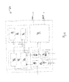
- All sensors - pressure difference sensor 16, temperature sensor 20 and velocity sensor 22 - transmit the sensed values to an electronic control unit 24 which is provided in the vehicle 10 to control, regulate and monitor all functions of the vehicle 10, in particular the functions of a combustion engine arranged in the vehicle 10.
- the electronic control unit 24 is shown in greater detail in fig. 2 .
- the electronic control unit 24 comprises a recording device 26 to record values measured by the different sensors 16, 20, 22 arranged in the vehicle 10. Therefore, the recording device 26 comprises a velocity recording element 28, which records the velocity values sensed by the velocity sensor 22, a temperature recording element 30, which records the temperature of the exhaust gas 14 sensed by the temperature sensor 20, and a pressure difference recording element 32, which records the pressure difference prevailing in the particle filter 12 measured by the pressure difference sensor 16. Additionally, in the recording device 26 there is provided at least one further recording element 34 which records additional information about for example the driving behavior of the vehicle 10.
- the electronic control unit 24 comprises a memory device 36 in which a plurality of control maps are stored, for example a map 38, which relates a general drive index GI of the vehicle 10, a physical condition of the particle filter 12 and a current drive pattern DP of the vehicle 10 to the necessity if an active regeneration cycle should be carried out.
- a map 38 which relates a general drive index GI of the vehicle 10, a physical condition of the particle filter 12 and a current drive pattern DP of the vehicle 10 to the necessity if an active regeneration cycle should be carried out.
- the electronic control unit 24 comprises a processing device 40 in which at least an index calculator 42 and a trigger calculator 44 are provided.
- the index calculator 42 With the index calculator 42 a general drive index GI of the vehicle 10 is calculated based on a statistic processing of a plurality of drive patterns DP of the vehicle 10.
- the calculated general drive index GI is transmitted to an index memory 46 in the memory device 36.
- the values of the velocity in the velocity recording element 28, the pressure difference in the pressure difference recording element 32 and the general drive index GI in the index memory 46 are transmitted to the trigger calculator 44 together with the map 38, which is stored in the memory device 36. Based on this data the trigger calculator 44 carries out a trigger method with which it can be decided if an active regeneration cycle should take place or not. The trigger method will be later explained in greater detail.
- the trigger calculator 44 transmits the calculated result to a signal output device 48.
- This signal output device 48 can put out a signal to carry out the active regeneration cycle, in case in the trigger calculator 44 the result is obtained that the active regeneration cycle should take place.
- the signal output device 48 can also put out a warn signal in order to induce manual cleaning of the particle filter 12.
- Fig. 3 shows a flow chart representing the steps with which in the index calculator 42 it can be decided with which general drive index GI the vehicle 10 is normally driven.
- a first step after the start of the method in the index calculator 42 it is counted during a drive cycle DC, i.e. during an interval between the start and the stop of the vehicle 10, how often the vehicle 10 attains a velocity of at least 50 km/h and how often the vehicle 10 attains a velocity of less than 50 km/h.
- a velocity of 50 km/h and more corresponds to a first drive pattern DP 1 and a velocity of the vehicle 10 of less than 50 km/h corresponds to a second drive pattern DP 2 .
- the time duration t of each drive pattern DP 1 , DP 2 is recorded.
- the second step it is evaluated if at least one of the first drive patterns DP 1 in the considered drive cycle DC has a time duration t which is long enough to carry out a complete active regeneration cycle of the particle filter 12, for example 10 minutes. If this is the case, the drive style DS in the considered drive cycle DC is evaluated as being a fast drive style FDS. If the time duration of all first drive patterns DP 1 in the considered drive cycle DC does not exceed the threshold time duration to carry out a complete active regeneration cycle, it is determined which of the drive patterns DP 1 or DP 2 was predominating in the considered drive cycle DC based on the counted number of each drive pattern DP.
- the drive style DS in the considered drive cycle DC is evaluated as being a fast drive style FDS
- the drive style DS is evaluated as being a slow drive style SDS.
- the drive style DS is evaluated. For a predefined number of drive cycles DC the number of fast drive styles FDS and slow drive styles SDS is counted in the next step. In a following step the number of fast drive styles FDS and slow drive styles SDS are compared and in case the number of fast drive styles FDS is predominating, it is determined and recorded that the vehicle 10 is generally driven in the first general drive index GI 1 . In case the number of slow drive styles is predominating, it is determined and recorded that the vehicle 10 is generally driven in the second general drive index GI 2 .
- the general drive index GI of the vehicle 10 is calculated in the index calculator 42 according to the above described method, the general drive index GI is stored in the index memory 46.
- the trigger calculator 44 When deciding if the active regeneration cycle of the particle filter 12 should be triggered, the trigger calculator 44 carries out the trigger method as described in the following with reference to fig 4 .
- the current velocity of the vehicle 10 and therefore the current drive pattern DP of the vehicle 10 is measured by the velocity sensor 22 and fed via the velocity recording element 28 into the trigger calculator 44.
- the velocity and therefore the drive pattern DP of the vehicle 10 is favorable to carry out the active regeneration cycle.
- a favorable drive pattern DP is a velocity of at least 50 km/h where the temperature is high enough to guarantee an effective active regeneration cycle.
- the value of the pressure difference measured by the pressure difference sensor 16 is fed to the trigger calculator 44 via the pressure difference recording element 32 and it is evaluated if the pressure difference indicates a critical soot value in the particle filter 12.
- soot value in the particle filter 12 is critical, but the drive pattern DP of the vehicle 10 is currently not favorable to carry out the active regeneration cycle, a warn signal is put out by the signal output device 48 indicating that the particle filter 12 needs cleaning. In case the soot amount in the particle filter 12 is not critical, the method returns back to carry out the first step of evaluating the vehicle velocity.
- the trigger calculator 44 uses information from the index memory 46 in which general drive index GI the vehicle 10 is generally driven. In case the general drive index GI of the vehicle 10 is the second general drive index GI 2 , the active regeneration cycle is carried out.
- the general drive index GI of the vehicle 10 is the first general drive index GI 1
- the pressure difference does not indicate a favorable state of the particle filter 12, for example because the particle filter 12 is not clogged enough
- the method returns to the first step of evaluating the velocity of the vehicle 10.
- the active regeneration cycle is carried out.
- the drive patterns DP are monitored and the different drive styles DS are sorted according to the considered drive cycles DC, whereas the duration of each type of drive pattern DP is considered such that more weightage is given to the first drive pattern DP 1 which is the favorable drive pattern DP to carry out the active regeneration cycle.
- the maximum duration after considering the weightage is identified and that drive style DS is assigned to the current drive cycle DC. This is stored over a number of drive cycles DC.
- a map 38 is shown which represents a diagram showing in which situations the active regeneration cycle is favorable.
- the active regeneration cycle is usually only favorable if a soot amount of at least 50 % is attained. This criterion holds in particular if the vehicle 10 is generally driven in the first general drive index GI 1 . But there are also vehicles 10 which are only seldom driven with the first drive pattern DP 1 and therefore the probability that a favorable drive pattern DP can be attained is low.
- the second general drive index GI 2 it is already favorable to carry out the active regeneration cycle below the threshold value of 50 % soot amount as soon as a drive pattern DP is attained which is favorable to carry out active regeneration.
- Fig. 6 shows a matrix which summarizes the above criteria.
- GI unfavorable
- F favorable
- the active regeneration cycle is only carried out if the soot amount has attained a favorable (F) value. If the vehicle 10 is generally driven in the second drive index GI 2 , the active regeneration cycle is also carried out if the favorable (F) soot amount in the particle filter 12 is not yet attained.
- Fig. 7 shows diagrams representing the statistic evaluation of the general drive index GI of a first vehicle 10.
- the velocity v of the vehicle 10 is plotted against the time t
- a current drive pattern DP of the vehicle 10 is plotted against the time t
- the extracted drive style DS is plotted against the time t
- the recorded general drive index GI is plotted against the time t.
- the drive style DS of the first drive cycle DC is set to slow drive style DS according to for example a city driver.
- the general drive index GI is the second general drive index GI 2 according to a slow general drive index GI.
- Fig. 9 shows the situation for a third vehicle 10 which is often driven in a slow city drive, but occasionally goes, for example, to a highway for sufficiently long enough time to complete an active regeneration cycle. Therefore, after four drive cycles DC the general drive index GI is evaluated as being the first general drive index GI 1 .
- the favorable drive pattern DP is the pattern in which the particle filter 12 inlet temperature is sufficiently high to start and successfully complete the active regeneration cycle with minimal fuel penalty.
- the regeneration cycle is governed by the soot load and the inlet temperature of the particle filter 12. If the driver does not drive so as to have a high particle filter 12 inlet temperature, then it is better to start the active regeneration cycle at lower soot loads to avoid overloading and insufficient heat for successful regeneration.
Landscapes
- Engineering & Computer Science (AREA)
- Chemical & Material Sciences (AREA)
- Combustion & Propulsion (AREA)
- Mechanical Engineering (AREA)
- General Engineering & Computer Science (AREA)
- Processes For Solid Components From Exhaust (AREA)
Abstract
Description
- The invention relates to a trigger method with which an active regeneration cycle of a particle filter which is arranged in a vehicle can be started.
- Particle filters in vehicles, in particular in vehicles using a combustion engine, are designed to remove particulate matter (soot) from the exhaust gas of the combustion engine. In particular, such particle filters are used in diesel combustion engines to filter the exhaust gas of the diesel engine.
- Unlike a catalytic converter, which is a flow-through device, a particle filter retains bigger exhaust gas particles by forcing the gas to flow through the filter. There are a variety of particulate filter technologies available, each designed around similar requirements such as fine filtration, minimum pressure drop, low cost, mass production suitability and product durability.
- During use the particle filter gets clogged by the accumulating soot, such that the particle filter needs regeneration from time to time. During the so called active regeneration cycle a certain program is run in a manner that elevates the exhaust temperature in conjunction with an extra fuel injection in the exhaust stream gas, such that fuel is injected to burn off the accumulated soot and convert it to ash. The fuel can, for example, be injected into the combustion chambers of the combustion engine to create hotter than normal exhaust gases by which the particles in the particle filter are burned off.
- There are situations in which this system does not always work, in particular in vehicles which are doing a high proportion of short runs from cold starts. In these cases instead of burning off the particles, the extra fuel can instead find its way into the engine's sump where it contaminates, for example, the lubrication oil being present.
- Hence, for the active regeneration cycle to be effective, the vehicle needs to be in a favorable current drive pattern, in which the regeneration cycle can be completed after being started.
- Therefore, the active regeneration cycle of the particle filter is triggered by various strategies. For a successful complete regeneration to happen with little fuel penalty, it is necessary that the current drive pattern is aiding the regeneration. For the regeneration to finish, once started, it is needed a minimum duration to stay in regeneration mode. During this duration of time, the drive pattern has to be maintained. This will reduce the fuel needed to raise and maintain the temperature for regeneration.
- Object of the invention is to provide a trigger method with which a complete active regeneration cycle can be provided.
- This object is attained by a trigger method with the feature combination of independent claim 1.
- Advantageous features of the trigger method are defined in the independent claims.
- A trigger method to start an active regeneration cycle of a particle filter arranged in a vehicle comprises the following steps:
- a) recording a general drive index of the vehicle;
- b) sensing a current physical condition of the particle filter;
- c) sensing a current drive pattern of the vehicle;
- d) affirming or negating a regeneration necessity based on a map relating the general drive index of the vehicle, the physical condition of the particle filter and the current drive pattern of the vehicle to the regeneration necessity.
- Hence, in the trigger method three different parameters are used to forecast if a successful complete regeneration cycle can be carried out. These three parameters are a general drive index of the vehicle which indicates in which manner the vehicle is generally driven, the current physical condition of the particle filter which indicates if it is already necessary to regenerate the particle filter, and a current drive pattern of the vehicle which indicates how the vehicle is driven at the moment.
- The map which relates all three parameters to the decision if the regeneration of the particle filter is necessary or not, is deposited in advance of carrying out the trigger method, wherein from the map it can be drawn, if the overall situation of the vehicle is suitable to carry out the active regeneration cycle of the particle filter. In a preferred embodiment of the invention the vehicle in which the trigger method is carried out is a combustion engine, in particular a diesel combustion engine, wherein diesel is used as the combustion fuel.
- In a preferred embodiment the regeneration necessity is affirmed for a first general drive index if both the physical condition of the particle filter and the current drive pattern of the vehicle are sensed as being favorable for the active regeneration. Therefore, in the case a first general drive index is present in the vehicle, the active regeneration cycle is only carried out if the physical condition as well as the current drive pattern with which the vehicle is driven at the moment fulfill the requirement "favorable for the active regeneration". For a second general drive index the regeneration necessity is affirmed if the current drive pattern of the vehicle is sensed as being favorable for the regeneration independently of the sensed physical condition of the particle filter. Therefore, if the second general drive index of the vehicle is present, it is not necessary that the physical condition of the particle filter fulfills the requirement "favorable", but it is only required that the drive pattern of the vehicle at the moment is in the favorable state.
- In a preferred embodiment before step a) a first drive pattern is defined as being favorable for the regeneration, and a second drive pattern is defined as being unfavorable for the regeneration. In particular, the first drive pattern is a drive pattern with a vehicle velocity of at least 50 km/h and the second drive pattern is a drive pattern with a vehicle velocity of less than 50 km/h.
- The higher the velocity of a vehicle, the higher is the temperature which is generated in the exhaust gas of the vehicle and therefore in the area of the particle filter. It is known that at a higher temperature of the particle filter a complete burning off of the particles in the particle filter can be attained which is not the case if the temperature is too low. Therefore, a drive pattern can advantageously only be favorable for the regeneration if the velocity of the vehicle is high enough to attain the necessary temperature in the particle filter to burn off the particles. Hence, there is a first drive pattern defined which corresponds to a sufficient high velocity of the vehicle and is therefore favorable for the regeneration. Additionally, a second drive pattern is defined in which the vehicle does not attain the necessary velocity and therefore the second drive pattern is defined as being unfavorable for the regeneration.
- In a preferred embodiment the regeneration necessity is affirmed if the drive pattern is sensed as being favorable for the regeneration. Hence, the active regeneration cycle is preferably carried out if the drive pattern guarantees a sufficient temperature in the particle filter such that a successful regeneration cycle can be carried out.
- Preferably before step a) a soot load of the particle filter is defined as being the physical condition of the particle filter to be sensed in step b). The soot load corresponds to the portion of a surface of the particle filter which is clogged by particles such that this portion cannot be active anymore when filtering the exhaust gas of the vehicle. It is defined that a soot load of at least 50 % of the particle filter is defined as being favorable for the regeneration. It is preferred if the active regeneration cycle of the particle filter is only carried out if it is really necessary, as in order to carry out the regeneration cycle additional fuel is needed. In order to save fuel and energy, the regeneration cycle should not be carried out too often. A threshold value from whereon it is okay to carry out the regeneration cycle is the defined favorable soot load.
- Preferably, the soot load of the particle filter is sensed by providing a pressure difference sensor in the particle filter. By monitoring the pressure difference over the particle filter, the soot load, i.e. the amount of particles being present in the particle filter, can preferably be monitored. Alternatively or additionally it is also possible to monitor the driving behavior of the vehicle and deduce out of this driving behavior the soot load in the particle filter.
- In a preferred embodiment a temperature of an exhaust gas of the vehicle which is filtered by the particle filter is measured upstream the particle filter. The temperature measurement enables additional monitoring if at the moment the situation in the vehicle is suitable to carry out the active regeneration cycle. Even if the drive pattern is in the favorable condition to carry out the active regeneration cycle as the vehicle velocity is at least 50 km/h, it is possible that the temperature in the exhaust gas and therefore in the particle filter is not yet high enough to successfully burn off the particles. Therefore, it is preferred to additionally monitor the temperature of the exhaust gas.
- In a preferred embodiment the general drive index of the vehicle is recorded by evaluating a predetermined number of recorded drive styles of successive drive cycles of the vehicle. By "drive cycle" of the vehicle an interval between a start of the vehicle and a stop of the vehicle is to be understood. During this drive cycle a plurality of drive patterns are present, wherein the vehicle drives at least 50 km/h or less than 50 km/h. Therefore, a "drive cycle" is the sum of all first drive patterns and second drive patterns. In this drive cycle the vehicle is driven in a drive style which is an average of all drive patterns being present during this drive cycle. The general drive index of the vehicle, i.e. the manner in which the vehicle is predictably generally driven over a longer time slot, is an average of a plurality of drive styles. Preferably, at least three drive styles, which happen successively, are used to record the general drive index of the vehicle.
- In a preferred embodiment the drive style of a drive cycle is recorded as being a first drive style, which is in particular a fast drive style, or as being a second drive style, which is in particular a slow drive style. For example, the first drive style is corresponding to a drive style in the drive cycle where the vehicle is driven mostly on a highway. In this case, the vehicle mostly has a velocity of more than 50 km/h and mostly drives in the first drive pattern. But it is also possible that the vehicle is driven mainly in the city where the vehicle velocity is less than 50 km/h and where the drive style is therefore a slow drive style, which is defined as being the second drive style. When determining if the drive style of a considered drive cycle is a first drive style or a second drive style the number of the first drive patterns in the drive cycle and the number of the second drive patterns in the drive cycle are counted.
- In case the number of the first drive patterns in this considered drive cycle predominates, the drive style is recorded as being the first drive style. In case the number of the second drive patterns predominates in the considered drive cycle, the drive style in this drive cycle is recorded as being the second drive style.
- In a preferred embodiment the time duration of each counted first and second drive patterns in the drive cycle is recorded and the number of the first and second drive patterns in the drive cycle are weighted, if at least one of the counted first drive patterns in the drive cycle exceeds a predefined threshold time duration. In case at least one time in a drive cycle a first drive pattern, i.e. a velocity of more than 50 km/h, is present for a sufficient time span, then it can be concluded that in this drive cycle the active regeneration cycle could have been carried out successfully. Therefore, there is no need to characterize this considered drive cycle as having a slow drive style and therefore define it as being a second drive style, but it is possible to define it as being a first drive style.
- In a preferred embodiment the predefined threshold time duration is defined as being a time duration needed to complete the active regeneration cycle after the start of the active regeneration cycle, which in particular is a time duration of at least 10 minutes. If the time duration of at least one of the first drive patterns in the drive cycle is exceeding this threshold time duration, the drive style of the drive cycle is recorded as being the first drive style.
- In a preferred embodiment a first general drive index is recorded if at evaluation of the predetermined number of drive styles the first drive style predominates. The first general drive index is in particular a fast general drive index. A second general drive index is recorded if at evaluation of the predetermined number of drive styles the second drive style predominates. The second general drive index is in particular a slow general drive index.
- Therefore, out of the monitoring of all drive patterns being present in a single drive cycle, it can be concluded in which drive style a vehicle was driven during this drive cycle. If a vehicle is driven generally in a fast drive style, then it can be concluded that the vehicle will be generally driven in the fast drive style and the first general drive index is recorded. If during a plurality of drive cycles the vehicle is always driven with the second drive pattern, i.e. a slow drive pattern, it can be concluded that also in the future the vehicle will have a higher probability to be driven with the second drive pattern again. Therefore, in this case, the general drive index is recorded as being the second general drive index.
- Hence, by observing the drive pattern of the vehicle over a number of driving cycles it can be decided as to when the active regeneration cycle can start.
- Out of the general drive index it can be derived a probability of the vehicle to meet a favorable condition to carry out a successful active regeneration cycle. Therefore, the trigger for starting the active regeneration cycle is based on the physical condition of the particle filter, the current drive pattern of the vehicle and the general drive index of the vehicle which gives the probability if a favorable drive pattern of the vehicle to carry out the active regeneration cycle can be met again in the future.
- Therefore, if the vehicle seldom does a favorable drive pattern and the soot load in the particle filter is not high, and if the vehicle currently is in a favorable drive pattern, the active regeneration cycle is triggered to make use of the seldom favorable drive pattern to reduce the fuel penalty.
- If the vehicle frequently does a favorable drive pattern, the active regeneration cycle is only started when the soot load in the particle filter is high enough. Knowing that this vehicle has a record of frequenting the favorable drive pattern the active regeneration cycle will be started at the next favorable drive pattern after exceeding the predefined soot load limit.
- In a preferred embodiment if a regeneration necessity is affirmed in step d) the active regeneration cycle of the particle filter is started.
- Preferably the trigger method is carried out in an electronic control unit of the vehicle.
- In a preferred embodiment, if the regeneration necessity in step d) is continuously negated and a soot load of the particle filter is exceeding a predefined threshold value, a warn signal is put out by the electronic control unit. The predefined threshold value can be a critical value of the particle filter which, for example, can be a soot load of 100 %.
- A preferred embodiment of the invention will be explained in the following with reference to the accompanying drawings, wherein
- Fig. 1
- shows a vehicle comprising a particle filter and an electronic control unit which triggers an active regeneration cycle of the particle filter;
- Fig. 2
- shows a detailed schematic view of the electronic control unit of
fig. 1 ; - Fig. 3
- shows a flow chart representing the steps carried out to determine if a vehicle is driven in a first general drive index or in a second general drive index;
- Fig. 4
- shows a flow chart representing the steps carried out to determine if an active regeneration cycle should be triggered or not;
- Fig. 5
- shows a diagram of a temperature of the particle filter in
fig. 1 versus the soot load of the particle filter, wherein at a certain soot load it is necessary to carry out the active regeneration cycle; - Fig. 6
- shows a matrix indicating at which general drive index and current drive pattern of the vehicle the active regeneration cycle is unfavorable or favorable;
- Fig. 7
- shows diagrams representing the statistic evaluation of the general drive index of a first vehicle;
- Fig. 8
- shows diagrams representing the statistic evaluation of the general drive index of a second vehicle; and
- Fig. 9
- shows diagrams representing the statistic evaluation of the general drive index of a third vehicle.
-
Fig. 1 shows avehicle 10, in particular a car, which comprises aparticle filter 12 being arranged in thevehicle 10 to filterexhaust gases 14 being a product of a combustion process of a combustion engine. - In the particle filter, a pressure difference sensor 16 is arranged which can sense the pressure difference over the
particle filter 12. Additionally, upstream theparticle filter 12 in anexhaust pipe 18, atemperature sensor 20 is arranged to measure the temperature of theexhaust gas 14 near theparticle filter 12. Further, avelocity sensor 22 is provided in thevehicle 10 which can measure the velocity of thevehicle 10 when in a driving state. - The pressure difference measured by the pressure difference sensor 16 in the
particle filter 12 gives information about the soot amount, i.e. the amount of particles which have already been filtered out by theparticle filter 12 and therefore are at the moment clogging theparticle filter 12 such that in this region where the clogging particles are present theparticle filter 12 is not effective anymore. - All sensors - pressure difference sensor 16,
temperature sensor 20 and velocity sensor 22 - transmit the sensed values to anelectronic control unit 24 which is provided in thevehicle 10 to control, regulate and monitor all functions of thevehicle 10, in particular the functions of a combustion engine arranged in thevehicle 10. - The
electronic control unit 24 is shown in greater detail infig. 2 . Theelectronic control unit 24 comprises arecording device 26 to record values measured by thedifferent sensors vehicle 10. Therefore, therecording device 26 comprises a velocity recording element 28, which records the velocity values sensed by thevelocity sensor 22, atemperature recording element 30, which records the temperature of theexhaust gas 14 sensed by thetemperature sensor 20, and a pressure difference recording element 32, which records the pressure difference prevailing in theparticle filter 12 measured by the pressure difference sensor 16. Additionally, in therecording device 26 there is provided at least one further recording element 34 which records additional information about for example the driving behavior of thevehicle 10. - Besides the
recording device 26 theelectronic control unit 24 comprises a memory device 36 in which a plurality of control maps are stored, for example amap 38, which relates a general drive index GI of thevehicle 10, a physical condition of theparticle filter 12 and a current drive pattern DP of thevehicle 10 to the necessity if an active regeneration cycle should be carried out. - Besides the
recording device 26 and the memory device 36 theelectronic control unit 24 comprises a processing device 40 in which at least anindex calculator 42 and atrigger calculator 44 are provided. With the index calculator 42 a general drive index GI of thevehicle 10 is calculated based on a statistic processing of a plurality of drive patterns DP of thevehicle 10. The calculated general drive index GI is transmitted to an index memory 46 in the memory device 36. - The values of the velocity in the velocity recording element 28, the pressure difference in the pressure difference recording element 32 and the general drive index GI in the index memory 46 are transmitted to the
trigger calculator 44 together with themap 38, which is stored in the memory device 36. Based on this data thetrigger calculator 44 carries out a trigger method with which it can be decided if an active regeneration cycle should take place or not. The trigger method will be later explained in greater detail. - The
trigger calculator 44 transmits the calculated result to asignal output device 48. Thissignal output device 48 can put out a signal to carry out the active regeneration cycle, in case in thetrigger calculator 44 the result is obtained that the active regeneration cycle should take place. In case thetrigger calculator 44 does not calculate that the active regeneration cycle should take place for a longer time period in which theparticle filter 12 is clogged to a critical point, thesignal output device 48 can also put out a warn signal in order to induce manual cleaning of theparticle filter 12. -
Fig. 3 shows a flow chart representing the steps with which in theindex calculator 42 it can be decided with which general drive index GI thevehicle 10 is normally driven. - In a first step after the start of the method in the
index calculator 42 it is counted during a drive cycle DC, i.e. during an interval between the start and the stop of thevehicle 10, how often thevehicle 10 attains a velocity of at least 50 km/h and how often thevehicle 10 attains a velocity of less than 50 km/h. A velocity of 50 km/h and more corresponds to a first drive pattern DP1 and a velocity of thevehicle 10 of less than 50 km/h corresponds to a second drive pattern DP2. At the same time of counting, the time duration t of each drive pattern DP1, DP2 is recorded. - Therefore, in the second step it is evaluated if at least one of the first drive patterns DP1 in the considered drive cycle DC has a time duration t which is long enough to carry out a complete active regeneration cycle of the
particle filter 12, for example 10 minutes. If this is the case, the drive style DS in the considered drive cycle DC is evaluated as being a fast drive style FDS. If the time duration of all first drive patterns DP1 in the considered drive cycle DC does not exceed the threshold time duration to carry out a complete active regeneration cycle, it is determined which of the drive patterns DP1 or DP2 was predominating in the considered drive cycle DC based on the counted number of each drive pattern DP. In case the first drive pattern DP1 was predominating, the drive style DS in the considered drive cycle DC is evaluated as being a fast drive style FDS, whereas in case the second drive pattern DP2 was predominating in the considered drive cycle DC, the drive style DS is evaluated as being a slow drive style SDS. - Therefore, for each drive cycle DC the drive style DS is evaluated. For a predefined number of drive cycles DC the number of fast drive styles FDS and slow drive styles SDS is counted in the next step. In a following step the number of fast drive styles FDS and slow drive styles SDS are compared and in case the number of fast drive styles FDS is predominating, it is determined and recorded that the
vehicle 10 is generally driven in the first general drive index GI1. In case the number of slow drive styles is predominating, it is determined and recorded that thevehicle 10 is generally driven in the second general drive index GI2. - After the general drive index GI of the
vehicle 10 is calculated in theindex calculator 42 according to the above described method, the general drive index GI is stored in the index memory 46. - When deciding if the active regeneration cycle of the
particle filter 12 should be triggered, thetrigger calculator 44 carries out the trigger method as described in the following with reference tofig 4 . - After starting the method first, the current velocity of the
vehicle 10 and therefore the current drive pattern DP of thevehicle 10 is measured by thevelocity sensor 22 and fed via the velocity recording element 28 into thetrigger calculator 44. In the next step in thetrigger calculator 44 it is decided if the velocity and therefore the drive pattern DP of thevehicle 10 is favorable to carry out the active regeneration cycle. A favorable drive pattern DP is a velocity of at least 50 km/h where the temperature is high enough to guarantee an effective active regeneration cycle. In case it is decided that the current drive pattern DP is not favorable to carry out the active regeneration cycle, the value of the pressure difference measured by the pressure difference sensor 16 is fed to thetrigger calculator 44 via the pressure difference recording element 32 and it is evaluated if the pressure difference indicates a critical soot value in theparticle filter 12. If the soot value in theparticle filter 12 is critical, but the drive pattern DP of thevehicle 10 is currently not favorable to carry out the active regeneration cycle, a warn signal is put out by thesignal output device 48 indicating that theparticle filter 12 needs cleaning. In case the soot amount in theparticle filter 12 is not critical, the method returns back to carry out the first step of evaluating the vehicle velocity. - In a next step after evaluating that the drive pattern DP is favorable to carry out the active regeneration cycle the
trigger calculator 44 uses information from the index memory 46 in which general drive index GI thevehicle 10 is generally driven. In case the general drive index GI of thevehicle 10 is the second general drive index GI2, the active regeneration cycle is carried out. - In case the general drive index GI of the
vehicle 10 is the first general drive index GI1, in a further step it is evaluated if the pressure difference and therefore the soot amount in theparticle filter 12 is favorable for the active regeneration cycle. In case the pressure difference does not indicate a favorable state of theparticle filter 12, for example because theparticle filter 12 is not clogged enough, the method returns to the first step of evaluating the velocity of thevehicle 10. In case the pressure difference indicates a clogging of theparticle filter 12 and therefore a high enough soot amount, the active regeneration cycle is carried out. - Therefore, when evaluating the general drive index GI the drive patterns DP are monitored and the different drive styles DS are sorted according to the considered drive cycles DC, whereas the duration of each type of drive pattern DP is considered such that more weightage is given to the first drive pattern DP1 which is the favorable drive pattern DP to carry out the active regeneration cycle. At the end of the drive cycle DC the maximum duration after considering the weightage is identified and that drive style DS is assigned to the current drive cycle DC. This is stored over a number of drive cycles DC.
- Out of the general drive index GI it is possible to address conditions that normally cause an incomplete active regeneration cycle. Usually, in frequent short distance journeys a high soot loading is occurring while at the same time the regeneration of the
particle filter 12 does not take place because the conditions necessary were not fulfilled. Sometimes frequent interrupted regenerations can happen, i.e. the engine was switched off during regeneration. This can for example apply toshort journey vehicles 10 which have at least fulfilled the conditions for triggering regeneration. - In
fig. 5 amap 38 is shown which represents a diagram showing in which situations the active regeneration cycle is favorable. In the diagram the temperature of theparticle filter 12 measured by thetemperature sensor 20 in theexhaust pipe 18 is plotted against the soot amount in theparticle filter 12. The active regeneration cycle is usually only favorable if a soot amount of at least 50 % is attained. This criterion holds in particular if thevehicle 10 is generally driven in the first general drive index GI1. But there are alsovehicles 10 which are only seldom driven with the first drive pattern DP1 and therefore the probability that a favorable drive pattern DP can be attained is low. Hence, forvehicles 10 with the second general drive index GI2 it is already favorable to carry out the active regeneration cycle below the threshold value of 50 % soot amount as soon as a drive pattern DP is attained which is favorable to carry out active regeneration. -
Fig. 6 shows a matrix which summarizes the above criteria. For both general drive indices GI it is unfavorable (U) to carry out the active regeneration cycle if thevehicle 10 is driven in the second drive pattern DP2. Therefore, if thevehicle 10 is driven in a first drive pattern DP1, i.e. with at least 50 km/h, it is favorable (F) to carry out the active regeneration cycle. For the first general drive index GI1, where it can be expected that the favorable drive pattern DP is attained a plurality of times, additionally themap 38 offig. 5 is regarded. The active regeneration cycle is only carried out if the soot amount has attained a favorable (F) value. If thevehicle 10 is generally driven in the second drive index GI2, the active regeneration cycle is also carried out if the favorable (F) soot amount in theparticle filter 12 is not yet attained. -
Fig. 7 shows diagrams representing the statistic evaluation of the general drive index GI of afirst vehicle 10. In diagram a) the velocity v of thevehicle 10 is plotted against the time t, in diagram b) a current drive pattern DP of thevehicle 10 is plotted against the time t, in diagram c) the extracted drive style DS is plotted against the time t and in diagram d) the recorded general drive index GI is plotted against the time t. As can be seen, the velocity v in each drive cycle DC is lower than 50 km/h. Therefore, the drive pattern DP in each drive cycle DC is set to "1" = slow drive pattern. As there is no indication of a fast drive pattern with a velocity of at least 50 km/h, the drive style DS of the first drive cycle DC is set to slow drive style DS according to for example a city driver. After the third drive cycle DC the drive style DS has occurred three times and therefore the general drive index GI is the second general drive index GI2 according to a slow general drive index GI. -
Fig. 8 shows diagrams according tofig. 7 for asecond vehicle 10 which mostly drives with a vehicle speed of at least 50 km/h, where the drive pattern DP in each drive cycle DC is set to "3" = fast drive pattern. Therefore, after statistically evaluating the drive patterns DP in the single drive cycles DC thissecond vehicle 10 is evaluated as being generally driven in the first general drive index GI1, i.e. a fast general drive index GI. -
Fig. 9 shows the situation for athird vehicle 10 which is often driven in a slow city drive, but occasionally goes, for example, to a highway for sufficiently long enough time to complete an active regeneration cycle. Therefore, after four drive cycles DC the general drive index GI is evaluated as being the first general drive index GI1. - The favorable drive pattern DP is the pattern in which the
particle filter 12 inlet temperature is sufficiently high to start and successfully complete the active regeneration cycle with minimal fuel penalty. The regeneration cycle is governed by the soot load and the inlet temperature of theparticle filter 12. If the driver does not drive so as to have ahigh particle filter 12 inlet temperature, then it is better to start the active regeneration cycle at lower soot loads to avoid overloading and insufficient heat for successful regeneration.
Claims (15)
- Trigger method to start an active regeneration cycle of a particle filter (12) arranged in a vehicle (10), the method comprising the steps ofa) recording a general drive index (GI) of the vehicle (10);b) sensing a current physical condition of the particle filter (12);c) sensing a current drive pattern (DP) of the vehicle (10);d) affirming or negating a regeneration necessity based on a map (38) relating the general drive index (GI) of the vehicle (10), the physical condition of the particle filter (12) and the current drive pattern (DP) of the vehicle (10) to the regeneration necessity.
- Trigger method according to claim 1,
characterized in that the regeneration necessity is affirmed for a first general drive index (GI1) if both the physical condition of the particle filter (12) and the current drive pattern (DP) of the vehicle (10) are sensed as being favorable (F) for the active regeneration and the regeneration necessity is affirmed for a second general drive index (GI2) if the current drive pattern (DP) of the vehicle (10) is sensed as being favorable (F) for the regeneration independently of the sensed physical condition of the particle filter (12). - Trigger method according to any of the claims 1 or 2,
characterized in that before step a) a first drive pattern (DP1), in particular a drive pattern (DP) with a vehicle velocity (v) of at least 50 km/h, is defined as being favorable (F) for the regeneration, and a second drive pattern (DP2), in particular a drive pattern (DP) with a vehicle velocity (v) of less than 50 km/h, is defined as being unfavorable (U) for the regeneration. - Trigger method according to claim 3,
characterized in that the regeneration necessity is affirmed if the drive pattern (DP) is sensed as being favorable (F) for the regeneration. - Trigger method according to any of the claims 1 to 4,
characterized in that before step a) a soot load of the particle filter (12) is defined as being the physical condition of the particle filter (12) to be sensed in step b), wherein a soot load of at least 50% of the particle filter (12) is defined as being favorable (F) for the regeneration. - Trigger method according to claim 5,
characterized in that the soot load of the particle filter (12) is sensed by providing a pressure difference sensor (16) in the particle filter (12) and/or by monitoring a driving behavior of the vehicle (10). - Trigger method according to any of the claims 1 to 6,
characterized in that a temperature of an exhaust gas (14) of the vehicle (10) being filtered by the particle filter (12) is measured upstream the particle filter (12). - Trigger method according to any of the claims 1 to 7,
characterized in that the general drive index (GI) of the vehicle (10) is recorded by evaluating a predetermined number of recorded drive styles (DS) of successive drive cycles (DC) of the vehicle (10), in particular at least three drive styles (DS), wherein a drive cycle (DC) of the vehicle (10) is defined as being an interval between a start of the vehicle (10) and a stop of the vehicle (10). - Trigger method according to claim 8 and to claim 3,
characterized in that the drive style (DS) of a drive cycle (DC) is recorded as being a first drive style (DS), in particular a fast drive style (FDS), or as being a second drive style (DS), in particular a slow drive style (SDS), by counting the number of the first drive patterns (DP1) in the drive cycle (DC) and the number of the second drive patterns (DP2) in the drive cycle (DC), and by recording the drive style (DS) of the drive cycle (DC)as the first drive style (DS) if the number of the first drive patterns (DP1) predominates in the drive cycle (DC) and by recording the drive style (DS) of the drive cycle (DC) as the second drive style (DS) if the number of the second drive patterns (DP2) predominates in the drive cycle (DC). - Trigger method according to claim 9,
characterized in that the time duration (t) of each counted first and second drive patterns (DP1, DP2) in the drive cycle (DC) is recorded and that the number of the first and second drive patterns (DP1, DP2) in the drive cycle (DC) are weighted if at least one of the counted first drive patterns (DP1) in the drive cycle (DC) exceeds a predefined threshold time duration. - Trigger method according to claim 10,
characterized in that the predefined threshold time duration is defined as being a time duration (t) needed to complete the active regeneration cycle after the start of the active regeneration cycle, in particular at least 10 min, wherein if the time duration (t) of at least one of the first drive patterns (DP1) in the drive cycle (DC) is exceeding the threshold time duration, the drive style (DS) of the drive cycle (DC) is recorded as being the first drive style (DS). - Trigger method according to any of the claims 9 to 11,
characterized in that a first general drive index (GI1), in particular a fast general drive index, is recorded if at evaluation of the predetermined number of drive styles (DS) the first drive style (DS) predominates, and wherein a second general drive index (Gl2), in particular a slow general drive index, is recorded if at evaluation of the predetermined number of drive styles the second drive style (DS) predominates. - Trigger method according to any of the claims 1 to 12,
characterized in that if a regeneration necessity is affirmed in step d) the active regeneration cycle of the particle filter (12) is started. - Trigger method according to any of the claims 1 to 13,
characterized in that the trigger method is carried out in an electronic control unit (24) of the vehicle (10). - Trigger method according to claim 14,
characterized in that if the regeneration necessity in step d) is continuously negated and a soot load of the particle filter (12) is exceeding a predefined threshold value, in particular a soot load of 100 %, a warn signal is put out by the electronic control unit (24).
Priority Applications (1)
| Application Number | Priority Date | Filing Date | Title |
|---|---|---|---|
| EP15165317.7A EP3088714B8 (en) | 2015-04-28 | 2015-04-28 | Trigger method to start an active regeneration cycle of a particle filter in a vehicle |
Applications Claiming Priority (1)
| Application Number | Priority Date | Filing Date | Title |
|---|---|---|---|
| EP15165317.7A EP3088714B8 (en) | 2015-04-28 | 2015-04-28 | Trigger method to start an active regeneration cycle of a particle filter in a vehicle |
Publications (3)
| Publication Number | Publication Date |
|---|---|
| EP3088714A1 true EP3088714A1 (en) | 2016-11-02 |
| EP3088714B1 EP3088714B1 (en) | 2019-06-12 |
| EP3088714B8 EP3088714B8 (en) | 2019-07-17 |
Family
ID=53015615
Family Applications (1)
| Application Number | Title | Priority Date | Filing Date |
|---|---|---|---|
| EP15165317.7A Active EP3088714B8 (en) | 2015-04-28 | 2015-04-28 | Trigger method to start an active regeneration cycle of a particle filter in a vehicle |
Country Status (1)
| Country | Link |
|---|---|
| EP (1) | EP3088714B8 (en) |
Cited By (1)
| Publication number | Priority date | Publication date | Assignee | Title |
|---|---|---|---|---|
| CN108952984A (en) * | 2017-05-26 | 2018-12-07 | 福特全球技术公司 | System and method for particulate filter regeneration |
Citations (4)
| Publication number | Priority date | Publication date | Assignee | Title |
|---|---|---|---|---|
| EP1195508A2 (en) * | 2000-10-07 | 2002-04-10 | DaimlerChrysler AG | Process for operating an exhaust gas purification device of a motor vehicle internal combustion engine |
| EP1203877A1 (en) * | 2000-11-03 | 2002-05-08 | Peugeot Citroen Automobiles SA | System for assisting the regeneration of a particle filter comprised in the exhaust pipe of a diesel vehicle engine |
| EP1439294A2 (en) * | 2003-01-16 | 2004-07-21 | Nissan Motor Co., Ltd. | Regeneration of diesel particulate filter |
| US20100154389A1 (en) * | 2008-02-08 | 2010-06-24 | Schumacher Sascha | Procedure for regenerating an exhaust gas after treatment system |
-
2015
- 2015-04-28 EP EP15165317.7A patent/EP3088714B8/en active Active
Patent Citations (4)
| Publication number | Priority date | Publication date | Assignee | Title |
|---|---|---|---|---|
| EP1195508A2 (en) * | 2000-10-07 | 2002-04-10 | DaimlerChrysler AG | Process for operating an exhaust gas purification device of a motor vehicle internal combustion engine |
| EP1203877A1 (en) * | 2000-11-03 | 2002-05-08 | Peugeot Citroen Automobiles SA | System for assisting the regeneration of a particle filter comprised in the exhaust pipe of a diesel vehicle engine |
| EP1439294A2 (en) * | 2003-01-16 | 2004-07-21 | Nissan Motor Co., Ltd. | Regeneration of diesel particulate filter |
| US20100154389A1 (en) * | 2008-02-08 | 2010-06-24 | Schumacher Sascha | Procedure for regenerating an exhaust gas after treatment system |
Cited By (1)
| Publication number | Priority date | Publication date | Assignee | Title |
|---|---|---|---|---|
| CN108952984A (en) * | 2017-05-26 | 2018-12-07 | 福特全球技术公司 | System and method for particulate filter regeneration |
Also Published As
| Publication number | Publication date |
|---|---|
| EP3088714B8 (en) | 2019-07-17 |
| EP3088714B1 (en) | 2019-06-12 |
Similar Documents
| Publication | Publication Date | Title |
|---|---|---|
| CN101379284B (en) | Method for controlling exhaust gas purification system, and exhaust gas purification system | |
| JP5562697B2 (en) | DPF regeneration control device, regeneration control method, and regeneration support system | |
| US9482124B2 (en) | Method for detecting abnormally frequent diesel particulate filter regeneration, engine and exhaust aftertreatment system, and warning system and method | |
| CN102165151B (en) | Method and apparatus for controlling regeneration of a particulate filter | |
| EP1905991A1 (en) | Control method of exhaust gas purification system and exhaust gas purification system | |
| RU2484266C2 (en) | Method and device for detection of combustion in particle filter | |
| EP2929157B1 (en) | On board diagnosis of the condition of an exhaust particle filter | |
| US20050267670A1 (en) | Method for monitoring a particle filter | |
| JP2007315275A (en) | Exhaust purification filter failure diagnosis apparatus and method | |
| CN113565610A (en) | Method for judging working state of diesel vehicle particle catcher | |
| EP3926160B1 (en) | Air filter deterioration determination device of construction machine | |
| US8685140B2 (en) | Particle filter and a method for operating a particle filter | |
| JP2003155916A (en) | Exhaust gas purification device control method | |
| EP3230565B1 (en) | Method and system for managing a regeneration of a particulate filter | |
| EP3088714B1 (en) | Trigger method to start an active regeneration cycle of a particle filter in a vehicle | |
| CN114718707B (en) | DPF fault diagnosis method for engineering vehicle and vehicle controller | |
| JP6414802B2 (en) | Engine oil deterioration diagnosis device for diesel engine | |
| KR101339237B1 (en) | Method for detecting breakage of dpf | |
| CN115111034A (en) | Non-sensing active regeneration method of particle catcher and vehicle with same | |
| JP7375674B2 (en) | Control devices, internal combustion engine systems and diagnostic methods | |
| CN118088338B (en) | Abnormality detection method, device and electronic control device of intake air flow sensor | |
| EP1762718B1 (en) | Process for regeneration of a particulate filter | |
| CN112443380B (en) | Method for monitoring a particle filter by means of a particle sensor | |
| EP1900918A1 (en) | Particulate filter regeneration method | |
| KR101134975B1 (en) | Initial dpf regeneration method |
Legal Events
| Date | Code | Title | Description |
|---|---|---|---|
| PUAI | Public reference made under article 153(3) epc to a published international application that has entered the european phase |
Free format text: ORIGINAL CODE: 0009012 |
|
| AK | Designated contracting states |
Kind code of ref document: A1 Designated state(s): AL AT BE BG CH CY CZ DE DK EE ES FI FR GB GR HR HU IE IS IT LI LT LU LV MC MK MT NL NO PL PT RO RS SE SI SK SM TR |
|
| AX | Request for extension of the european patent |
Extension state: BA ME |
|
| 17P | Request for examination filed |
Effective date: 20170502 |
|
| RBV | Designated contracting states (corrected) |
Designated state(s): AL AT BE BG CH CY CZ DE DK EE ES FI FR GB GR HR HU IE IS IT LI LT LU LV MC MK MT NL NO PL PT RO RS SE SI SK SM TR |
|
| STAA | Information on the status of an ep patent application or granted ep patent |
Free format text: STATUS: REQUEST FOR EXAMINATION WAS MADE |
|
| GRAJ | Information related to disapproval of communication of intention to grant by the applicant or resumption of examination proceedings by the epo deleted |
Free format text: ORIGINAL CODE: EPIDOSDIGR1 |
|
| STAA | Information on the status of an ep patent application or granted ep patent |
Free format text: STATUS: GRANT OF PATENT IS INTENDED |
|
| GRAP | Despatch of communication of intention to grant a patent |
Free format text: ORIGINAL CODE: EPIDOSNIGR1 |
|
| INTG | Intention to grant announced |
Effective date: 20181120 |
|
| RIN1 | Information on inventor provided before grant (corrected) |
Inventor name: KUPPUSAMY, VENKATASUBRAMANIYAN Inventor name: MAHAVEERA, HARSHA Inventor name: DHARMALINGAM, MUTHUKUMARASWAMY |
|
| GRAS | Grant fee paid |
Free format text: ORIGINAL CODE: EPIDOSNIGR3 |
|
| GRAA | (expected) grant |
Free format text: ORIGINAL CODE: 0009210 |
|
| STAA | Information on the status of an ep patent application or granted ep patent |
Free format text: STATUS: THE PATENT HAS BEEN GRANTED |
|
| AK | Designated contracting states |
Kind code of ref document: B1 Designated state(s): AL AT BE BG CH CY CZ DE DK EE ES FI FR GB GR HR HU IE IS IT LI LT LU LV MC MK MT NL NO PL PT RO RS SE SI SK SM TR |
|
| REG | Reference to a national code |
Ref country code: GB Ref legal event code: FG4D |
|
| REG | Reference to a national code |
Ref country code: CH Ref legal event code: EP |
|
| REG | Reference to a national code |
Ref country code: AT Ref legal event code: REF Ref document number: 1142851 Country of ref document: AT Kind code of ref document: T Effective date: 20190615 |
|
| REG | Reference to a national code |
Ref country code: CH Ref legal event code: PK Free format text: BERICHTIGUNG B8 |
|
| RAP2 | Party data changed (patent owner data changed or rights of a patent transferred) |
Owner name: CPT GROUP GMBH |
|
| REG | Reference to a national code |
Ref country code: DE Ref legal event code: R096 Ref document number: 602015031654 Country of ref document: DE |
|
| REG | Reference to a national code |
Ref country code: IE Ref legal event code: FG4D |
|
| REG | Reference to a national code |
Ref country code: NL Ref legal event code: MP Effective date: 20190612 |
|
| REG | Reference to a national code |
Ref country code: LT Ref legal event code: MG4D |
|
| PG25 | Lapsed in a contracting state [announced via postgrant information from national office to epo] |
Ref country code: HR Free format text: LAPSE BECAUSE OF FAILURE TO SUBMIT A TRANSLATION OF THE DESCRIPTION OR TO PAY THE FEE WITHIN THE PRESCRIBED TIME-LIMIT Effective date: 20190612 Ref country code: LT Free format text: LAPSE BECAUSE OF FAILURE TO SUBMIT A TRANSLATION OF THE DESCRIPTION OR TO PAY THE FEE WITHIN THE PRESCRIBED TIME-LIMIT Effective date: 20190612 Ref country code: FI Free format text: LAPSE BECAUSE OF FAILURE TO SUBMIT A TRANSLATION OF THE DESCRIPTION OR TO PAY THE FEE WITHIN THE PRESCRIBED TIME-LIMIT Effective date: 20190612 Ref country code: NO Free format text: LAPSE BECAUSE OF FAILURE TO SUBMIT A TRANSLATION OF THE DESCRIPTION OR TO PAY THE FEE WITHIN THE PRESCRIBED TIME-LIMIT Effective date: 20190912 Ref country code: SE Free format text: LAPSE BECAUSE OF FAILURE TO SUBMIT A TRANSLATION OF THE DESCRIPTION OR TO PAY THE FEE WITHIN THE PRESCRIBED TIME-LIMIT Effective date: 20190612 Ref country code: AL Free format text: LAPSE BECAUSE OF FAILURE TO SUBMIT A TRANSLATION OF THE DESCRIPTION OR TO PAY THE FEE WITHIN THE PRESCRIBED TIME-LIMIT Effective date: 20190612 |
|
| PG25 | Lapsed in a contracting state [announced via postgrant information from national office to epo] |
Ref country code: LV Free format text: LAPSE BECAUSE OF FAILURE TO SUBMIT A TRANSLATION OF THE DESCRIPTION OR TO PAY THE FEE WITHIN THE PRESCRIBED TIME-LIMIT Effective date: 20190612 Ref country code: GR Free format text: LAPSE BECAUSE OF FAILURE TO SUBMIT A TRANSLATION OF THE DESCRIPTION OR TO PAY THE FEE WITHIN THE PRESCRIBED TIME-LIMIT Effective date: 20190913 Ref country code: BG Free format text: LAPSE BECAUSE OF FAILURE TO SUBMIT A TRANSLATION OF THE DESCRIPTION OR TO PAY THE FEE WITHIN THE PRESCRIBED TIME-LIMIT Effective date: 20190912 Ref country code: RS Free format text: LAPSE BECAUSE OF FAILURE TO SUBMIT A TRANSLATION OF THE DESCRIPTION OR TO PAY THE FEE WITHIN THE PRESCRIBED TIME-LIMIT Effective date: 20190612 |
|
| RAP2 | Party data changed (patent owner data changed or rights of a patent transferred) |
Owner name: VITESCO TECHNOLOGIES GMBH |
|
| REG | Reference to a national code |
Ref country code: AT Ref legal event code: MK05 Ref document number: 1142851 Country of ref document: AT Kind code of ref document: T Effective date: 20190612 |
|
| PG25 | Lapsed in a contracting state [announced via postgrant information from national office to epo] |
Ref country code: PT Free format text: LAPSE BECAUSE OF FAILURE TO SUBMIT A TRANSLATION OF THE DESCRIPTION OR TO PAY THE FEE WITHIN THE PRESCRIBED TIME-LIMIT Effective date: 20191014 Ref country code: RO Free format text: LAPSE BECAUSE OF FAILURE TO SUBMIT A TRANSLATION OF THE DESCRIPTION OR TO PAY THE FEE WITHIN THE PRESCRIBED TIME-LIMIT Effective date: 20190612 Ref country code: NL Free format text: LAPSE BECAUSE OF FAILURE TO SUBMIT A TRANSLATION OF THE DESCRIPTION OR TO PAY THE FEE WITHIN THE PRESCRIBED TIME-LIMIT Effective date: 20190612 Ref country code: CZ Free format text: LAPSE BECAUSE OF FAILURE TO SUBMIT A TRANSLATION OF THE DESCRIPTION OR TO PAY THE FEE WITHIN THE PRESCRIBED TIME-LIMIT Effective date: 20190612 Ref country code: EE Free format text: LAPSE BECAUSE OF FAILURE TO SUBMIT A TRANSLATION OF THE DESCRIPTION OR TO PAY THE FEE WITHIN THE PRESCRIBED TIME-LIMIT Effective date: 20190612 Ref country code: SK Free format text: LAPSE BECAUSE OF FAILURE TO SUBMIT A TRANSLATION OF THE DESCRIPTION OR TO PAY THE FEE WITHIN THE PRESCRIBED TIME-LIMIT Effective date: 20190612 Ref country code: AT Free format text: LAPSE BECAUSE OF FAILURE TO SUBMIT A TRANSLATION OF THE DESCRIPTION OR TO PAY THE FEE WITHIN THE PRESCRIBED TIME-LIMIT Effective date: 20190612 |
|
| REG | Reference to a national code |
Ref country code: DE Ref legal event code: R081 Ref document number: 602015031654 Country of ref document: DE Owner name: VITESCO TECHNOLOGIES GMBH, DE Free format text: FORMER OWNER: CONTINENTAL AUTOMOTIVE GMBH, 30165 HANNOVER, DE |
|
| PG25 | Lapsed in a contracting state [announced via postgrant information from national office to epo] |
Ref country code: IT Free format text: LAPSE BECAUSE OF FAILURE TO SUBMIT A TRANSLATION OF THE DESCRIPTION OR TO PAY THE FEE WITHIN THE PRESCRIBED TIME-LIMIT Effective date: 20190612 Ref country code: ES Free format text: LAPSE BECAUSE OF FAILURE TO SUBMIT A TRANSLATION OF THE DESCRIPTION OR TO PAY THE FEE WITHIN THE PRESCRIBED TIME-LIMIT Effective date: 20190612 Ref country code: IS Free format text: LAPSE BECAUSE OF FAILURE TO SUBMIT A TRANSLATION OF THE DESCRIPTION OR TO PAY THE FEE WITHIN THE PRESCRIBED TIME-LIMIT Effective date: 20191012 Ref country code: SM Free format text: LAPSE BECAUSE OF FAILURE TO SUBMIT A TRANSLATION OF THE DESCRIPTION OR TO PAY THE FEE WITHIN THE PRESCRIBED TIME-LIMIT Effective date: 20190612 |
|
| REG | Reference to a national code |
Ref country code: DE Ref legal event code: R097 Ref document number: 602015031654 Country of ref document: DE |
|
| PG25 | Lapsed in a contracting state [announced via postgrant information from national office to epo] |
Ref country code: TR Free format text: LAPSE BECAUSE OF FAILURE TO SUBMIT A TRANSLATION OF THE DESCRIPTION OR TO PAY THE FEE WITHIN THE PRESCRIBED TIME-LIMIT Effective date: 20190612 |
|
| PLBE | No opposition filed within time limit |
Free format text: ORIGINAL CODE: 0009261 |
|
| STAA | Information on the status of an ep patent application or granted ep patent |
Free format text: STATUS: NO OPPOSITION FILED WITHIN TIME LIMIT |
|
| PG25 | Lapsed in a contracting state [announced via postgrant information from national office to epo] |
Ref country code: DK Free format text: LAPSE BECAUSE OF FAILURE TO SUBMIT A TRANSLATION OF THE DESCRIPTION OR TO PAY THE FEE WITHIN THE PRESCRIBED TIME-LIMIT Effective date: 20190612 Ref country code: PL Free format text: LAPSE BECAUSE OF FAILURE TO SUBMIT A TRANSLATION OF THE DESCRIPTION OR TO PAY THE FEE WITHIN THE PRESCRIBED TIME-LIMIT Effective date: 20190612 |
|
| 26N | No opposition filed |
Effective date: 20200313 |
|
| PG25 | Lapsed in a contracting state [announced via postgrant information from national office to epo] |
Ref country code: SI Free format text: LAPSE BECAUSE OF FAILURE TO SUBMIT A TRANSLATION OF THE DESCRIPTION OR TO PAY THE FEE WITHIN THE PRESCRIBED TIME-LIMIT Effective date: 20190612 Ref country code: IS Free format text: LAPSE BECAUSE OF FAILURE TO SUBMIT A TRANSLATION OF THE DESCRIPTION OR TO PAY THE FEE WITHIN THE PRESCRIBED TIME-LIMIT Effective date: 20200224 |
|
| PG2D | Information on lapse in contracting state deleted |
Ref country code: IS |
|
| PG25 | Lapsed in a contracting state [announced via postgrant information from national office to epo] |
Ref country code: MC Free format text: LAPSE BECAUSE OF FAILURE TO SUBMIT A TRANSLATION OF THE DESCRIPTION OR TO PAY THE FEE WITHIN THE PRESCRIBED TIME-LIMIT Effective date: 20190612 |
|
| REG | Reference to a national code |
Ref country code: CH Ref legal event code: PL |
|
| PG25 | Lapsed in a contracting state [announced via postgrant information from national office to epo] |
Ref country code: FR Free format text: LAPSE BECAUSE OF NON-PAYMENT OF DUE FEES Effective date: 20200430 Ref country code: CH Free format text: LAPSE BECAUSE OF NON-PAYMENT OF DUE FEES Effective date: 20200430 Ref country code: LI Free format text: LAPSE BECAUSE OF NON-PAYMENT OF DUE FEES Effective date: 20200430 Ref country code: LU Free format text: LAPSE BECAUSE OF NON-PAYMENT OF DUE FEES Effective date: 20200428 |
|
| REG | Reference to a national code |
Ref country code: BE Ref legal event code: MM Effective date: 20200430 |
|
| PG25 | Lapsed in a contracting state [announced via postgrant information from national office to epo] |
Ref country code: BE Free format text: LAPSE BECAUSE OF NON-PAYMENT OF DUE FEES Effective date: 20200430 |
|
| GBPC | Gb: european patent ceased through non-payment of renewal fee |
Effective date: 20200428 |
|
| PG25 | Lapsed in a contracting state [announced via postgrant information from national office to epo] |
Ref country code: IE Free format text: LAPSE BECAUSE OF NON-PAYMENT OF DUE FEES Effective date: 20200428 Ref country code: GB Free format text: LAPSE BECAUSE OF NON-PAYMENT OF DUE FEES Effective date: 20200428 |
|
| REG | Reference to a national code |
Ref country code: DE Ref legal event code: R081 Ref document number: 602015031654 Country of ref document: DE Owner name: SCHAEFFLER TECHNOLOGIES AG & CO. KG, DE Free format text: FORMER OWNER: VITESCO TECHNOLOGIES GMBH, 30165 HANNOVER, DE Ref country code: DE Ref legal event code: R081 Ref document number: 602015031654 Country of ref document: DE Owner name: VITESCO TECHNOLOGIES GMBH, DE Free format text: FORMER OWNER: VITESCO TECHNOLOGIES GMBH, 30165 HANNOVER, DE |
|
| PG25 | Lapsed in a contracting state [announced via postgrant information from national office to epo] |
Ref country code: MT Free format text: LAPSE BECAUSE OF FAILURE TO SUBMIT A TRANSLATION OF THE DESCRIPTION OR TO PAY THE FEE WITHIN THE PRESCRIBED TIME-LIMIT Effective date: 20190612 Ref country code: CY Free format text: LAPSE BECAUSE OF FAILURE TO SUBMIT A TRANSLATION OF THE DESCRIPTION OR TO PAY THE FEE WITHIN THE PRESCRIBED TIME-LIMIT Effective date: 20190612 |
|
| PG25 | Lapsed in a contracting state [announced via postgrant information from national office to epo] |
Ref country code: MK Free format text: LAPSE BECAUSE OF FAILURE TO SUBMIT A TRANSLATION OF THE DESCRIPTION OR TO PAY THE FEE WITHIN THE PRESCRIBED TIME-LIMIT Effective date: 20190612 |
|
| P01 | Opt-out of the competence of the unified patent court (upc) registered |
Effective date: 20230530 |
|
| REG | Reference to a national code |
Ref country code: DE Ref legal event code: R081 Ref document number: 602015031654 Country of ref document: DE Owner name: SCHAEFFLER TECHNOLOGIES AG & CO. KG, DE Free format text: FORMER OWNER: VITESCO TECHNOLOGIES GMBH, 93055 REGENSBURG, DE |
|
| PGFP | Annual fee paid to national office [announced via postgrant information from national office to epo] |
Ref country code: DE Payment date: 20250430 Year of fee payment: 11 |