EP3088615A1 - Water-flow-adjustable water-saving bubbler - Google Patents
Water-flow-adjustable water-saving bubbler Download PDFInfo
- Publication number
- EP3088615A1 EP3088615A1 EP14875662.0A EP14875662A EP3088615A1 EP 3088615 A1 EP3088615 A1 EP 3088615A1 EP 14875662 A EP14875662 A EP 14875662A EP 3088615 A1 EP3088615 A1 EP 3088615A1
- Authority
- EP
- European Patent Office
- Prior art keywords
- water
- disposed
- switch shaft
- flow
- shaft
- Prior art date
- Legal status (The legal status is an assumption and is not a legal conclusion. Google has not performed a legal analysis and makes no representation as to the accuracy of the status listed.)
- Granted
Links
Images
Classifications
-
- E—FIXED CONSTRUCTIONS
- E03—WATER SUPPLY; SEWERAGE
- E03C—DOMESTIC PLUMBING INSTALLATIONS FOR FRESH WATER OR WASTE WATER; SINKS
- E03C1/00—Domestic plumbing installations for fresh water or waste water; Sinks
- E03C1/02—Plumbing installations for fresh water
- E03C1/08—Jet regulators or jet guides, e.g. anti-splash devices
- E03C1/084—Jet regulators with aerating means
-
- B—PERFORMING OPERATIONS; TRANSPORTING
- B05—SPRAYING OR ATOMISING IN GENERAL; APPLYING FLUENT MATERIALS TO SURFACES, IN GENERAL
- B05B—SPRAYING APPARATUS; ATOMISING APPARATUS; NOZZLES
- B05B1/00—Nozzles, spray heads or other outlets, with or without auxiliary devices such as valves, heating means
- B05B1/30—Nozzles, spray heads or other outlets, with or without auxiliary devices such as valves, heating means designed to control volume of flow, e.g. with adjustable passages
- B05B1/3013—Lift valves
-
- E—FIXED CONSTRUCTIONS
- E03—WATER SUPPLY; SEWERAGE
- E03C—DOMESTIC PLUMBING INSTALLATIONS FOR FRESH WATER OR WASTE WATER; SINKS
- E03C1/00—Domestic plumbing installations for fresh water or waste water; Sinks
- E03C1/02—Plumbing installations for fresh water
- E03C2001/026—Plumbing installations for fresh water with flow restricting devices
-
- F—MECHANICAL ENGINEERING; LIGHTING; HEATING; WEAPONS; BLASTING
- F16—ENGINEERING ELEMENTS AND UNITS; GENERAL MEASURES FOR PRODUCING AND MAINTAINING EFFECTIVE FUNCTIONING OF MACHINES OR INSTALLATIONS; THERMAL INSULATION IN GENERAL
- F16L—PIPES; JOINTS OR FITTINGS FOR PIPES; SUPPORTS FOR PIPES, CABLES OR PROTECTIVE TUBING; MEANS FOR THERMAL INSULATION IN GENERAL
- F16L55/00—Devices or appurtenances for use in, or in connection with, pipes or pipe systems
- F16L55/02—Energy absorbers; Noise absorbers
- F16L55/027—Throttle passages
-
- Y—GENERAL TAGGING OF NEW TECHNOLOGICAL DEVELOPMENTS; GENERAL TAGGING OF CROSS-SECTIONAL TECHNOLOGIES SPANNING OVER SEVERAL SECTIONS OF THE IPC; TECHNICAL SUBJECTS COVERED BY FORMER USPC CROSS-REFERENCE ART COLLECTIONS [XRACs] AND DIGESTS
- Y02—TECHNOLOGIES OR APPLICATIONS FOR MITIGATION OR ADAPTATION AGAINST CLIMATE CHANGE
- Y02A—TECHNOLOGIES FOR ADAPTATION TO CLIMATE CHANGE
- Y02A20/00—Water conservation; Efficient water supply; Efficient water use
- Y02A20/40—Protecting water resources
- Y02A20/411—Water saving techniques at user level
Definitions
- the present invention relates to sanitary ware and water supplying field, especially to a water-saving flow regulator with flow volume switchable.
- Flow regulators are widely used in the sanitary wares and washing device as sanitary accessory.
- a flow regulator is used to regulate the water flowing to diffuse the water flowing to particles and to absorb air to mix with water to form washing water with a lot of bubbles.
- This kind of accessory has varies types that can be assembled to taps, shower heads, etc.
- the flow regulator can be used with a water-saving device to be made with water-saving function.
- this kind of flow regulator has only one working state, the water-saving state, it can not achieve high flow volume, which is limited in the applicability.
- the present invention is provided with a water-saving flow regulator with flow volume switchable to solve above mentioned technical problems.
- the switch shaft is disposed with a big end, the big end is sleeved on the sealing part.
- the center of the water diversion body is disposed with a hollow protruding, a plurality of water diversion holes are disposed at the edge of the protruding; the internal portion of the protruding is disposed with an accommodating chamber with an downward opening, the sealing part of the switch shaft closes the accommodating chamber when entering the accommodating chamber.
- the flow regulating device comprises an inlet body and a rectifier, the inlet body is disposed at the inlet port, the rectifier is disposed below the inlet body.
- the inlet body comprises a periphery wall, the bottom portion of the internal portion of the periphery wall is disposed with a baffle, a plurality of throughout holes are disposed at the baffle, the center of the baffle is disposed with a first shaft hole, the side of the first shaft hole facing to the water diversion body is disposed with a step hole with diameter enlarged.
- the rectifier is plate shaped with a plurality of concentric annular rings, a plurality of radial short columns are disposed between the annular rings, a water hole is formed between two adjacent short columns; the center of the rectifier is disposed with a second shaft hole to hold the switch shaft.
- the switch shaft is column shaped, the upper end of the switch shaft is disposed with two protrudings surrounding the periphery wall, an annular groove is formed between the two proturdings, the sealing part is a sealing ring assembled to the annular groove.
- the flow regulating device further comprises a flat filter assembled to the outlet portion of the flow regulating device, the center of the flat filter is disposed with a third shaft hole to hold the switch shaft.
- the flow regulator further comprises a switch shaft reset device, the switch shaft reset device comprises a spring, one end of the spring abuts against the switch shaft, the other end abuts against the bottom portion of the water diversion body.
- the axis of the end portion of the switch shaft is disposed with a spring position chamber
- the accommodating chamber of the bottom portion of the water diversion body is disposed with a position column inserted to the spring position chamber; one end of the spring is disposed in the spring position chamber of the switch shaft, the other end abuts against the position column of the water diversion body.
- the lower edge of the protruding of the water diversion body forms a hem
- the water diversion holes are disposed at the connecting of the hem and the protruding
- a reinforcing rib is disposed between two adjacent water diversion holes; the top portion of the protruding is an arc section.
- the flow regulating device comprises an inlet body and a rectifier; the inlet body comprises a periphery wall, the bottom portion of the internal portion of the periphery wall is disposed with a baffle, the baffle is disposed with a plurality of throughout holes; a position step and an assembly groove is disposed in the periphery wall of the inlet body above the baffle.
- the flow regulating device further comprises a filter and a flat filter; the flat filter, the rectifier and the inlet body are assembled in the housing in order; the switch shaft is disposed in the inlet body, the lower portion of the switch shaft passes through the inlet body, the rectifier, the flat filter and the housing in order; the water diversion body is assembled to the position step of the inlet body, the filter is assembled above the water diversion body, the assembly ring of the filter is embedded to the assembly groove of the inlet body; an inlet chamber is formed between the internal wall of the filter and the external periphery surface of the water diversion body; an outlet chamber is formed between the lower surface of the hem of the water diversion body and the upper surface of the baffle of the inlet body.
- the present invention is provided with a water-saving flow regulator with flow volume switchable, which has two working states. Normally is the water-saving state, the first flowing passage of the flow regulating device is closed by the switch shaft, water flows out of the second flowing passage.
- the water-saving state is suitable when low flow volume is required.
- the present invention is further disposed with a reset device.
- the switch shaft overcomes the action of the reset device to abut against the water diversion body, the switch shaft would not drop down.
- the switch shaft is pushed down by the action of the reset device to return to initial state, at this time, water flows out of only one flowing passage that it achieves forcible water-saving.
- the present invention has less component and smaller size, it can achieve free switch between two outlet states.
- a water-saving flow regulator with flow volume switchable of an detailed embodiment of the present invention comprises a filter 1, a water diversion body 2, an inlet body 4, a switch shaft 6, a rectifier 7 and a housing 9.
- the filter 1 is a semi-spherical shape with a plurality of throughout holes 11 used to diffuse the water flowing, the lower edge of the filter 1 is disposed with an assembly ring 12.
- the center of the water diversion body 2 is disposed with a column shaped protruding 21, a plurality of water diversion holes 22 are disposed at the lower edge of the protruding 21.
- the internal portion of the protruding 21 is disposed with an accommodating chamber 23 with a downward opening, the axis of the accommodating chamber is disposed with a downward position column 24.
- the lower edge of the column protruding 21 forms with a hem 25, the water diversion holes 22 are disposed at the connecting of the hem 25 and the protruding 21, a reinforcing rib 26 is disposed between two adjacent water diversion holes 22, the top portion of the column protruding 21 is an arc section 27 (as figured in FIG.1 , FIG.2, FIG.3 ).
- the inlet body comprises a periphery wall 41, the bottom portion of the internal portion of the periphery wall is disposed with a baffle 42, a plurality of throughout holes 43 are disposed at the baffle 42.
- the center of the baffle 42 is disposed with a first shaft hole 44, the side of the first shaft hole 44 facing to the water diversion body is disposed with a step hole 45 with diameter enlarged.
- a position step 46 and an assembly groove 47 are disposed above the baffle 42 of the periphery wall 41 in order.
- the switch shaft 6 is column shaped with large two ends and small center, the diameter of the central portion 65 is smaller than the diameter of the shaft hole 44 of the baffle 42, a flowing passage is formed between the center and the shaft hole 44.
- the upper end of the switch shaft 6 is disposed with two flanges 61, 62 surrounding the periphery wall, the diameter of the flange 61 is larger than the diameter of the shaft hole 44 and is smaller than the diameter of the step hole 45, so that the flange 61 can be inserted to the step hole 45 to close the flowing passage between the central portion 65 of the switch shaft 6 and the shaft hole 44.
- An annular groove 63 is formed between the two flanges, when assembling, the sealing ring 3 is locked to the annular groove 63 and is contacted with the internal wall of the step hole 45 to fully close the flowing passage.
- the switch shaft 6 is further disposed with an insert hole 64 with upward opening, the spring 5 is positioned in the insert hole 64.
- the rectifier 7 is plate shaped with a plurality of concentric annular rings 71, a plurality of radial short columns 72 are disposed between the annular rings, a water hole is formed between two adjacent short columns.
- the center of the rectifier is disposed with a second shaft hole to hole the switch shaft 6.
- the center of the flat filter 8 is disposed with a third shaft hole 83 to hold the switch shaft 6.
- the periphery wall of the housing 9 is disposed with a plurality of suction holes 91 with space, the center of the bottom plate at the internal portion of the housing is disposed with a fourth shaft hole 93 to hold the switch shaft 6.
- the bottom plate at the periphery of the fourth shaft hole 93 is disposed with an outlet 92.
- the flat filter 8, the rectifier 7 and the inlet body 4 of the present invention are assembled in the housing 9 in order;
- the switch shaft 6 is assembled in the inlet body 4, the lower portion 66 of the switch shaft 6 passes through the first shaft hole 44, the second shaft hole 73 of the rectifier, the third shaft hole 83 of the flat filter and the fourth shaft hole 93 of the housing in order;
- the water diversion body 2 is assembled to the position step 46 of the inlet body 4, the filter 1 is assembled above the water diversion body 2, the assembly ring 12 is embedded to the assembly groove 47 of the inlet body 4.
- An inlet chamber is formed between the internal wall of the filter 1 and the external periphery surface of the water diversion body 2; an outlet chamber is formed between the lower surface of the hem 25 of the water diversion body and the top surface of the baffle 42 of the inlet body.
- the usage of the present invention is that: normally is the water-saving state, the flange 61 of the switch shaft 6 is inserted to the step hole 45 to close the flowing passage between the central portion 65 of the switch shaft and the shaft hole 44, the sealing ring 3 is disposed at the internal wall of the step hole 45 of the inlet body 4 for further sealing, to stop water flowing through the first shaft hole 44.
- the water from the filter 1 to the flow regulator flows through the water diversion hole 22 of the water diversion body 2 to flow downwardly to the throughout holes 43 of the inlet body 4, and then water is rectified by the rectifier 7 to mix with air to generate bubble water. Water flows out of the outlet at the bottom of the housing 9 after the buffering of the flat filter 8.
- the switch shaft 6 When high volume is required, the switch shaft 6 is pushed upwardly until the sealing ring 3 abuts against the internal wall of the protruding 21 of the water diversion body 2. Except the outlet route same as in the water-saving state, water flows downwardly from chamber between the switch shaft 6 and the internal wall of the first shaft hole 44 of the inlet body 4 and then flows out through the second shaft hole 73 of the rectifier 7, the third shaft hole 83 of the filter 8 and the fourth shaft hole 93 of the housing. As an outlet passage is added, it flows out in high volume that it can satisfy the need of washing vegetables.
- the present invention is provided with a water-saving flow regulator with flow volume switchable, when in the initial position, the sealing part of the switch shaft closes the first flowing passage of the flow regulating device, water flows out of the second flowing passage; when in a second position, the sealing part of the switch shaft leaves away from the flow regulating device, the second flowing passage is open and keeps open state under the water pressure, water flows out of the first and second flowing passage, the present invention can be freely switched in two outlet states that it has well industrial applicability.
Landscapes
- Health & Medical Sciences (AREA)
- Life Sciences & Earth Sciences (AREA)
- Engineering & Computer Science (AREA)
- Hydrology & Water Resources (AREA)
- Public Health (AREA)
- Water Supply & Treatment (AREA)
- Domestic Plumbing Installations (AREA)
- Flow Control (AREA)
- Lift Valve (AREA)
Abstract
Description
- The present invention relates to sanitary ware and water supplying field, especially to a water-saving flow regulator with flow volume switchable.
- Flow regulators are widely used in the sanitary wares and washing device as sanitary accessory. A flow regulator is used to regulate the water flowing to diffuse the water flowing to particles and to absorb air to mix with water to form washing water with a lot of bubbles. This kind of accessory has varies types that can be assembled to taps, shower heads, etc.
- The flow regulator can be used with a water-saving device to be made with water-saving function. However, this kind of flow regulator has only one working state, the water-saving state, it can not achieve high flow volume, which is limited in the applicability.
- The present invention is provided with a water-saving flow regulator with flow volume switchable to solve above mentioned technical problems.
- The technical proposal of the present invention is that:
- A water-saving flow regulator with flow volume switchable, comprising a housing and flow regulating device disposed in the housing, wherein further comprising a switch shaft and a water diversion body disposed above the flow regulating device, the switch shaft is sleeved with a sealing part, the flow regulating device is disposed with a shaft hole, the switch shaft is inserted in the shaft hole, a first flowing passage is formed between the switch shaft and the shaft hole wall of the flow regulating device; the periphery of the shaft hole is disposed with a plurality of through holes, the through holes form a second flowing passage, the bottom portion of the water diversion body forms a chamber, the switch shaft is movable between an initial position and a second position;
- in the initial position, the sealing part of the switch valve closes the first flowing passage of the flow regulating device, water only flows out of the second flowing passage;
- in the second position, the sealing part of the switch valve leaves away from the flow regulating device, the second flowing passage is open and keeps open under the water pressure, water flows out of the first flowing passage and the second flowing passage.
- In another preferred embodiment, the switch shaft is disposed with a big end, the big end is sleeved on the sealing part.
- In another preferred embodiment, the center of the water diversion body is disposed with a hollow protruding, a plurality of water diversion holes are disposed at the edge of the protruding; the internal portion of the protruding is disposed with an accommodating chamber with an downward opening, the sealing part of the switch shaft closes the accommodating chamber when entering the accommodating chamber.
- In another preferred embodiment, the flow regulating device comprises an inlet body and a rectifier, the inlet body is disposed at the inlet port, the rectifier is disposed below the inlet body.
- In another preferred embodiment, the inlet body comprises a periphery wall, the bottom portion of the internal portion of the periphery wall is disposed with a baffle, a plurality of throughout holes are disposed at the baffle, the center of the baffle is disposed with a first shaft hole, the side of the first shaft hole facing to the water diversion body is disposed with a step hole with diameter enlarged.
- In another preferred embodiment, the rectifier is plate shaped with a plurality of concentric annular rings, a plurality of radial short columns are disposed between the annular rings, a water hole is formed between two adjacent short columns; the center of the rectifier is disposed with a second shaft hole to hold the switch shaft.
- In another preferred embodiment, the switch shaft is column shaped, the upper end of the switch shaft is disposed with two protrudings surrounding the periphery wall, an annular groove is formed between the two proturdings, the sealing part is a sealing ring assembled to the annular groove.
- In another preferred embodiment, the flow regulating device further comprises a flat filter assembled to the outlet portion of the flow regulating device, the center of the flat filter is disposed with a third shaft hole to hold the switch shaft.
- In another preferred embodiment, the flow regulator further comprises a switch shaft reset device, the switch shaft reset device comprises a spring, one end of the spring abuts against the switch shaft, the other end abuts against the bottom portion of the water diversion body.
- In another preferred embodiment, the axis of the end portion of the switch shaft is disposed with a spring position chamber, the accommodating chamber of the bottom portion of the water diversion body is disposed with a position column inserted to the spring position chamber; one end of the spring is disposed in the spring position chamber of the switch shaft, the other end abuts against the position column of the water diversion body.
- In another preferred embodiment, the lower edge of the protruding of the water diversion body forms a hem, the water diversion holes are disposed at the connecting of the hem and the protruding, a reinforcing rib is disposed between two adjacent water diversion holes; the top portion of the protruding is an arc section.
- In another preferred embodiment, the flow regulating device comprises an inlet body and a rectifier; the inlet body comprises a periphery wall, the bottom portion of the internal portion of the periphery wall is disposed with a baffle, the baffle is disposed with a plurality of throughout holes; a position step and an assembly groove is disposed in the periphery wall of the inlet body above the baffle.
- In another preferred embodiment, the flow regulating device further comprises a filter and a flat filter; the flat filter, the rectifier and the inlet body are assembled in the housing in order; the switch shaft is disposed in the inlet body, the lower portion of the switch shaft passes through the inlet body, the rectifier, the flat filter and the housing in order; the water diversion body is assembled to the position step of the inlet body, the filter is assembled above the water diversion body, the assembly ring of the filter is embedded to the assembly groove of the inlet body; an inlet chamber is formed between the internal wall of the filter and the external periphery surface of the water diversion body; an outlet chamber is formed between the lower surface of the hem of the water diversion body and the upper surface of the baffle of the inlet body.
- As can be seen from above, the present invention is provided with a water-saving flow regulator with flow volume switchable, which has two working states. Normally is the water-saving state, the first flowing passage of the flow regulating device is closed by the switch shaft, water flows out of the second flowing passage. The water-saving state is suitable when low flow volume is required.
- When high flow volume is required, pushing the switch shaft up, the first flowing passage is open, water flows out of the first and second flowing passage, at this time, it is in high outlet volume that it can achieve high flow volume. The present invention is further disposed with a reset device. When in high volume state, with the water pressure pushing upwardly, the switch shaft overcomes the action of the reset device to abut against the water diversion body, the switch shaft would not drop down. When the tap is turned off, the switch shaft is pushed down by the action of the reset device to return to initial state, at this time, water flows out of only one flowing passage that it achieves forcible water-saving.
- The present invention has less component and smaller size, it can achieve free switch between two outlet states.
-
-
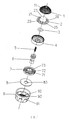
FIG.1 illustrates an exploded and schematic diagram of the present invention. -
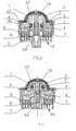
FIG.2 illustrates a sectional diagram of the present invention in water-saving state. -
FIG.3 illustrates a sectional diagram of the present invention in high volume state. -
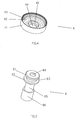
FIG.4 illustrates a schematic diagram of the inlet body. -
FIG.5 illustrates a schematic diagram of the switch shaft. -
- Filter 1, through
hole 11,assembly ring 12 -
Water diversion body 2, protruding 21,water diversion hole 22,accommodating chamber 23,position column 24,hem 25 Reinforcingrib 25,arc section 27 - O-
ring 3 -
Inlet body 4,periphery wall 41,baffle 42, throughouthole 43,first shaft hole 44,step hole 45, position step 46,assembly groove 47Spring 5 -
Switch shaft 6,flange insert hole 64,central portion 65,lower portion 66 - Rectifier 7, concentric
annular ring 71,short column 72,second shaft hole 73 -
Flat filter 8,third shaft hole 83 -
Housing 9,suction hole 91,outlet 92,fourth shaft hole 93 - Referring to
FIGs 1∼3 , a water-saving flow regulator with flow volume switchable of an detailed embodiment of the present invention comprises afilter 1, awater diversion body 2, aninlet body 4, aswitch shaft 6, arectifier 7 and ahousing 9. - The
filter 1 is a semi-spherical shape with a plurality of throughoutholes 11 used to diffuse the water flowing, the lower edge of thefilter 1 is disposed with anassembly ring 12. - The center of the
water diversion body 2 is disposed with a column shaped protruding 21, a plurality ofwater diversion holes 22 are disposed at the lower edge of the protruding 21. The internal portion of theprotruding 21 is disposed with anaccommodating chamber 23 with a downward opening, the axis of the accommodating chamber is disposed with adownward position column 24. The lower edge of the column protruding 21 forms with ahem 25, thewater diversion holes 22 are disposed at the connecting of thehem 25 and the protruding 21, a reinforcingrib 26 is disposed between two adjacentwater diversion holes 22, the top portion of the column protruding 21 is an arc section 27 (as figured inFIG.1 ,FIG.2, FIG.3 ). - Referring to
FIG.4 , the inlet body comprises aperiphery wall 41, the bottom portion of the internal portion of the periphery wall is disposed with abaffle 42, a plurality of throughoutholes 43 are disposed at thebaffle 42. The center of thebaffle 42 is disposed with afirst shaft hole 44, the side of thefirst shaft hole 44 facing to the water diversion body is disposed with astep hole 45 with diameter enlarged. A position step 46 and anassembly groove 47 are disposed above thebaffle 42 of theperiphery wall 41 in order. - Referring to
FIG.5 , theswitch shaft 6 is column shaped with large two ends and small center, the diameter of thecentral portion 65 is smaller than the diameter of theshaft hole 44 of thebaffle 42, a flowing passage is formed between the center and theshaft hole 44. - The upper end of the
switch shaft 6 is disposed with twoflanges flange 61 is larger than the diameter of theshaft hole 44 and is smaller than the diameter of thestep hole 45, so that theflange 61 can be inserted to thestep hole 45 to close the flowing passage between thecentral portion 65 of theswitch shaft 6 and theshaft hole 44. Anannular groove 63 is formed between the two flanges, when assembling, the sealingring 3 is locked to theannular groove 63 and is contacted with the internal wall of thestep hole 45 to fully close the flowing passage. Theswitch shaft 6 is further disposed with aninsert hole 64 with upward opening, thespring 5 is positioned in theinsert hole 64. - The
rectifier 7 is plate shaped with a plurality of concentricannular rings 71, a plurality of radialshort columns 72 are disposed between the annular rings, a water hole is formed between two adjacent short columns. The center of the rectifier is disposed with a second shaft hole to hole theswitch shaft 6. - The center of the
flat filter 8 is disposed with athird shaft hole 83 to hold theswitch shaft 6. - The periphery wall of the
housing 9 is disposed with a plurality of suction holes 91 with space, the center of the bottom plate at the internal portion of the housing is disposed with afourth shaft hole 93 to hold theswitch shaft 6. The bottom plate at the periphery of thefourth shaft hole 93 is disposed with anoutlet 92. - The
flat filter 8, therectifier 7 and theinlet body 4 of the present invention are assembled in thehousing 9 in order; theswitch shaft 6 is assembled in theinlet body 4, thelower portion 66 of theswitch shaft 6 passes through thefirst shaft hole 44, thesecond shaft hole 73 of the rectifier, thethird shaft hole 83 of the flat filter and thefourth shaft hole 93 of the housing in order; thewater diversion body 2 is assembled to the position step 46 of theinlet body 4, thefilter 1 is assembled above thewater diversion body 2, theassembly ring 12 is embedded to theassembly groove 47 of theinlet body 4. An inlet chamber is formed between the internal wall of thefilter 1 and the external periphery surface of thewater diversion body 2; an outlet chamber is formed between the lower surface of thehem 25 of the water diversion body and the top surface of thebaffle 42 of the inlet body. As the top portion of the column protruding 21 is disposed with an arc section that it makes water flowing smoothly, the reinforcingribs 26 disposed incline guarantee the strength of thewater diversion body 2 and smoothly water flowing. - The usage of the present invention is that: normally is the water-saving state, the
flange 61 of theswitch shaft 6 is inserted to thestep hole 45 to close the flowing passage between thecentral portion 65 of the switch shaft and theshaft hole 44, the sealingring 3 is disposed at the internal wall of thestep hole 45 of theinlet body 4 for further sealing, to stop water flowing through thefirst shaft hole 44. The water from thefilter 1 to the flow regulator flows through thewater diversion hole 22 of thewater diversion body 2 to flow downwardly to the throughout holes 43 of theinlet body 4, and then water is rectified by therectifier 7 to mix with air to generate bubble water. Water flows out of the outlet at the bottom of thehousing 9 after the buffering of theflat filter 8. - When high volume is required, the
switch shaft 6 is pushed upwardly until the sealingring 3 abuts against the internal wall of the protruding 21 of thewater diversion body 2. Except the outlet route same as in the water-saving state, water flows downwardly from chamber between theswitch shaft 6 and the internal wall of thefirst shaft hole 44 of theinlet body 4 and then flows out through thesecond shaft hole 73 of therectifier 7, thethird shaft hole 83 of thefilter 8 and thefourth shaft hole 93 of the housing. As an outlet passage is added, it flows out in high volume that it can satisfy the need of washing vegetables. - When in high volume state, with the water pressure pushing upwardly, the
switch shaft 6 overcomes the action of thespring 5 to abut against the internal wall of the protruding 21 of thewater diversion body 2, the switch shaft would not drop down. When the tap is turned off, the water pressure reduces, theswitch shaft 6 is pushed down by the action of thespring 5 to return to initial state, at this time, water flows out of only one flowing passage that it achieves forcible water-saving. - Although the present invention has been described with reference to the preferred embodiments thereof for carrying out the patent for invention, it is apparent to those skilled in the art that a variety of modifications and changes may be made without departing from the scope of the patent for invention which is intended to be defined by the appended claims.
- The present invention is provided with a water-saving flow regulator with flow volume switchable, when in the initial position, the sealing part of the switch shaft closes the first flowing passage of the flow regulating device, water flows out of the second flowing passage; when in a second position, the sealing part of the switch shaft leaves away from the flow regulating device, the second flowing passage is open and keeps open state under the water pressure, water flows out of the first and second flowing passage, the present invention can be freely switched in two outlet states that it has well industrial applicability.
Claims (13)
- A water-saving flow regulator with flow volume switchable, comprising a housing and flow regulating device disposed in the housing, wherein further comprising a switch shaft and a water diversion body disposed above the flow regulating device, the switch shaft is sleeved with a sealing part, the flow regulating device is disposed with a shaft hole, the switch shaft is inserted in the shaft hole, a first flowing passage is formed between the switch shaft and the shaft hole wall of the flow regulating device; the periphery of the shaft hole is disposed with a plurality of through holes, the through holes form a second flowing passage, the bottom portion of the water diversion body forms a chamber, the switch shaft is movable between an initial position and a second position;
in the initial position, the sealing part of the switch valve closes the first flowing passage of the flow regulating device, water only flows out of the second flowing passage;
in the second position, the sealing part of the switch valve leaves away from the flow regulating device, the second flowing passage is open and keeps open under the water pressure, water flows out of the first flowing passage and the second flowing passage. - The water-saving flow regulator with flow volume switchable according to claim 1, wherein the switch shaft is disposed with a big end, the big end is sleeved on the sealing part.
- The water-saving flow regulator with flow volume switchable according to claim 1, wherein the center of the water diversion body is disposed with a hollow protruding, a plurality of water diversion holes are disposed at the edge of the protruding; the internal portion of the protruding is disposed with an accommodating chamber with an downward opening, the sealing part of the switch shaft closes the accommodating chamber when entering the accommodating chamber.
- The water-saving flow regulator with flow volume switchable according to claim 1, wherein the flow regulating device comprises an inlet body and a rectifier, the inlet body is disposed at the inlet port, the rectifier is disposed below the inlet body.
- The water-saving flow regulator with flow volume switchable according to claim 4, wherein the inlet body comprises a periphery wall, the bottom portion of the internal portion of the periphery wall is disposed with a baffle, a plurality of throughout holes are disposed at the baffle, the center of the baffle is disposed with a first shaft hole, the side of the first shaft hole facing to the water diversion body is disposed with a step hole with diameter enlarged.
- The water-saving flow regulator with flow volume switchable according to claim 4, wherein the rectifier is plate shaped with a plurality of concentric annular rings, a plurality of radial short columns are disposed between the annular rings, a water hole is formed between two adjacent short columns; the center of the rectifier is disposed with a second shaft hole to hold the switch shaft.
- The water-saving flow regulator with flow volume switchable according to claim 1, wherein the switch shaft is column shaped, the upper end of the switch shaft is disposed with two protrudings surrounding the periphery wall, an annular groove is formed between the two proturdings, the sealing part is a sealing ring assembled to the annular groove.
- The water-saving flow regulator with flow volume switchable according to claim 1, wherein the flow regulating device further comprises a flat filter assembled to the outlet portion of the flow regulating device, the center of the flat filter is disposed with a third shaft hole to hold the switch shaft.
- The water-saving flow regulator with flow volume switchable according to claim 1, wherein the flow regulator further comprises a switch shaft reset device, the switch shaft reset device comprises a spring, one end of the spring abuts against the switch shaft, the other end abuts against the bottom portion of the water diversion body.
- The water-saving flow regulator with flow volume switchable according to claim 9, wherein the axis of the end portion of the switch shaft is disposed with a spring position chamber, the accommodating chamber of the bottom portion of the water diversion body is disposed with a position column inserted to the spring position chamber; one end of the spring is disposed in the spring position chamber of the switch shaft, the other end abuts against the position column of the water diversion body.
- The water-saving flow regulator with flow volume switchable according to claim 3, wherein the lower edge of the protruding of the water diversion body forms a hem, the water diversion holes are disposed at the connecting of the hem and the protruding, a reinforcing rib is disposed between two adjacent water diversion holes; the top portion of the protruding is an arc section.
- The water-saving flow regulator with flow volume switchable according to claim 11, wherein the flow regulating device comprises an inlet body and a rectifier; the inlet body comprises a periphery wall, the bottom portion of the internal portion of the periphery wall is disposed with a baffle, the baffle is disposed with a plurality of throughout holes; a position step and an assembly groove is disposed in the periphery wall of the inlet body above the baffle.
- The water-saving flow regulator with flow volume switchable according to claim 12, wherein the flow regulating device further comprises a filter and a flat filter; the flat filter, the rectifier and the inlet body are assembled in the housing in order; the switch shaft is disposed in the inlet body, the lower portion of the switch shaft passes through the inlet body, the rectifier, the flat filter and the housing in order; the water diversion body is assembled to the position step of the inlet body, the filter is assembled above the water diversion body, the assembly ring of the filter is embedded to the assembly groove of the inlet body; an inlet chamber is formed between the internal wall of the filter and the external periphery surface of the water diversion body; an outlet chamber is formed between the lower surface of the hem of the water diversion body and the upper surface of the baffle of the inlet body.
Applications Claiming Priority (3)
| Application Number | Priority Date | Filing Date | Title |
|---|---|---|---|
| CN201310731765.8A CN103696462B (en) | 2013-12-26 | 2013-12-26 | Water quantity switchable water-saving bubbler |
| CN201320868791.0U CN203625983U (en) | 2013-12-26 | 2013-12-26 | Water-saving bubbler capable of switching water volume |
| PCT/CN2014/094898 WO2015096759A1 (en) | 2013-12-26 | 2014-12-25 | Water-flow-adjustable water-saving bubbler |
Publications (3)
| Publication Number | Publication Date |
|---|---|
| EP3088615A1 true EP3088615A1 (en) | 2016-11-02 |
| EP3088615A4 EP3088615A4 (en) | 2017-08-09 |
| EP3088615B1 EP3088615B1 (en) | 2020-02-12 |
Family
ID=53477568
Family Applications (1)
| Application Number | Title | Priority Date | Filing Date |
|---|---|---|---|
| EP14875662.0A Active EP3088615B1 (en) | 2013-12-26 | 2014-12-25 | Water-flow-adjustable water-saving bubbler |
Country Status (3)
| Country | Link |
|---|---|
| US (1) | US9982423B2 (en) |
| EP (1) | EP3088615B1 (en) |
| WO (1) | WO2015096759A1 (en) |
Cited By (1)
| Publication number | Priority date | Publication date | Assignee | Title |
|---|---|---|---|---|
| CZ307612B6 (en) * | 2017-04-20 | 2019-01-09 | Wavitar s.r.o. | Perlátor |
Families Citing this family (5)
| Publication number | Priority date | Publication date | Assignee | Title |
|---|---|---|---|---|
| SE540044C2 (en) * | 2015-03-23 | 2018-03-06 | Ngl Teknik I Linkoeping Ab | ADJUSTABLE FLOW LIMITER FOR A MIXER AND A PROCEDURE FOR SETTING THE FLOW |
| WO2017107352A1 (en) * | 2015-12-23 | 2017-06-29 | 芜湖美的厨卫电器制造有限公司 | Flow regulating apparatus and gas water heater having same |
| CN109610569A (en) * | 2018-11-27 | 2019-04-12 | 厦门睿晨环境科技有限公司 | A dual-function automatic switching aerator |
| TWI722765B (en) * | 2020-01-16 | 2021-03-21 | 浩瀚國際有限公司 | Switching water saving valve |
| CN115451228B (en) * | 2022-10-11 | 2024-08-16 | 中交第一公路勘察设计研究院有限公司 | Pipe diameter automatic regulating device for centralized drainage system of highway bridge |
Family Cites Families (20)
| Publication number | Priority date | Publication date | Assignee | Title |
|---|---|---|---|---|
| DE3903800C2 (en) * | 1989-02-09 | 2001-12-06 | Wildfang Dieter Gmbh | Outlet device |
| US5085246A (en) * | 1990-05-22 | 1992-02-04 | Griinke Ralph E | Plural-rate surge-suppressing valve |
| US6131608A (en) * | 1999-06-08 | 2000-10-17 | Lu; Ke-Way | Water flowrate control device |
| US7219690B2 (en) * | 2004-03-11 | 2007-05-22 | Watkins Manufacturing Corporation | Flow control valve |
| US7143997B2 (en) * | 2005-01-03 | 2006-12-05 | Highplus International Co., Ltd. | Plug assembly for a faucet to automatically stop water flow |
| DE202006003342U1 (en) | 2006-03-01 | 2007-07-05 | Neoperl Gmbh | Flow controller for aerating water is fitted with circular grid made up of concentric rings and radial bars, water being divided into several streams as it flows through grid and strikes points where they cross |
| ATE504874T1 (en) * | 2006-12-06 | 2011-04-15 | Neoperl Gmbh | FLOW RATE REGULATOR |
| US7677473B2 (en) * | 2007-12-28 | 2010-03-16 | Highplus International Co., Ltd. | Spout for foaming and saving water |
| US7950624B2 (en) * | 2008-09-04 | 2011-05-31 | Hui-Fen Liao | Water valve apparatus |
| CN201351764Y (en) | 2009-01-10 | 2009-11-25 | 邝溢林 | Water faucet bubble former with improved structure |
| JP3182863U (en) * | 2010-02-12 | 2013-04-18 | 浩瀚国際有限公司 | Water-saving valve |
| CN201618625U (en) * | 2010-03-02 | 2010-11-03 | 厦门松霖科技有限公司 | A push-button water-saving shower |
| DE202010016867U1 (en) * | 2010-05-27 | 2011-09-14 | Neoperl Gmbh | Sanitary outlet insert |
| CN201972201U (en) | 2011-01-20 | 2011-09-14 | 厦门市易洁卫浴有限公司 | Rotary water-saving bubbler |
| CN102359154B (en) * | 2011-08-04 | 2013-03-27 | 厦门松霖科技有限公司 | Gas-water mixing bubbler |
| US9222599B2 (en) * | 2013-02-05 | 2015-12-29 | Highplus International Co., Ltd. | Self-closing water-saving valve assembly |
| CN103696462B (en) | 2013-12-26 | 2015-04-29 | 厦门松霖科技有限公司 | Water quantity switchable water-saving bubbler |
| CN203625983U (en) | 2013-12-26 | 2014-06-04 | 厦门松霖科技有限公司 | Water-saving bubbler capable of switching water volume |
| JP6277835B2 (en) * | 2014-04-08 | 2018-02-14 | 京三電機株式会社 | Fuel vapor control device |
| JP6176215B2 (en) * | 2014-09-25 | 2017-08-09 | 株式会社デンソー | Two-stage switching valve |
-
2014
- 2014-12-25 WO PCT/CN2014/094898 patent/WO2015096759A1/en not_active Ceased
- 2014-12-25 US US15/103,136 patent/US9982423B2/en active Active
- 2014-12-25 EP EP14875662.0A patent/EP3088615B1/en active Active
Cited By (1)
| Publication number | Priority date | Publication date | Assignee | Title |
|---|---|---|---|---|
| CZ307612B6 (en) * | 2017-04-20 | 2019-01-09 | Wavitar s.r.o. | Perlátor |
Also Published As
| Publication number | Publication date |
|---|---|
| EP3088615A4 (en) | 2017-08-09 |
| US20160298321A1 (en) | 2016-10-13 |
| EP3088615B1 (en) | 2020-02-12 |
| US9982423B2 (en) | 2018-05-29 |
| WO2015096759A1 (en) | 2015-07-02 |
Similar Documents
| Publication | Publication Date | Title |
|---|---|---|
| US9982423B2 (en) | Water saving flow regulator that is flow volume switchable | |
| CN202884121U (en) | Change-over valve | |
| CN106704700B (en) | Water saving device for faucet and method for using water saving device | |
| US9550195B1 (en) | Shower head | |
| US20150090812A1 (en) | Pilot valve switch mechanism and a combined shower applied with the pilot valve switch mechanism | |
| CN103696462B (en) | Water quantity switchable water-saving bubbler | |
| CN111804448B (en) | Multifunctional water outlet device | |
| JP2014513846A (en) | Flow regulator | |
| WO2018113129A1 (en) | Showerhead capable of quickly discharging residual water | |
| CN203625983U (en) | Water-saving bubbler capable of switching water volume | |
| JP5576179B2 (en) | Constant flow device | |
| GB2537209A (en) | A water saving mechanism with high flow volume in low pressure | |
| CN210386244U (en) | Shower with switchable water mode | |
| CN201284859Y (en) | Water feed current limiting valve | |
| CN106763889A (en) | A kind of difunctional bubbler of Automatic-reset | |
| CN218000408U (en) | Lifting type valve core capable of discharging water from valve rod | |
| CN108843807B (en) | Remote switching valve structure | |
| US6776189B1 (en) | Four-way switch structure of a fluid control valve | |
| CN206555557U (en) | A kind of water outlet control assembly mounted in watertap discharging tube | |
| US20100025612A1 (en) | Control valve for a water tap | |
| JP2021173057A (en) | Water faucet | |
| CN210713073U (en) | a bubbler | |
| CN104646208A (en) | Spray gun | |
| CN203730826U (en) | Toggle switch valve group and water outlet devices | |
| CN104455698B (en) | Water faucet for water purifier and water purifier having same |
Legal Events
| Date | Code | Title | Description |
|---|---|---|---|
| PUAI | Public reference made under article 153(3) epc to a published international application that has entered the european phase |
Free format text: ORIGINAL CODE: 0009012 |
|
| 17P | Request for examination filed |
Effective date: 20160726 |
|
| AK | Designated contracting states |
Kind code of ref document: A1 Designated state(s): AL AT BE BG CH CY CZ DE DK EE ES FI FR GB GR HR HU IE IS IT LI LT LU LV MC MK MT NL NO PL PT RO RS SE SI SK SM TR |
|
| AX | Request for extension of the european patent |
Extension state: BA ME |
|
| DAX | Request for extension of the european patent (deleted) | ||
| A4 | Supplementary search report drawn up and despatched |
Effective date: 20170710 |
|
| RIC1 | Information provided on ipc code assigned before grant |
Ipc: E03C 1/084 20060101AFI20170704BHEP Ipc: B05B 1/30 20060101ALI20170704BHEP |
|
| RAP1 | Party data changed (applicant data changed or rights of an application transferred) |
Owner name: XIAMEN SOLEX HIGH-TECH INDUSTRIES CO., LTD. Owner name: ZHOU, HUASONG |
|
| RAP1 | Party data changed (applicant data changed or rights of an application transferred) |
Owner name: XIAMEN SOLEX HIGH-TECH INDUSTRIES CO., LTD. |
|
| RAP1 | Party data changed (applicant data changed or rights of an application transferred) |
Owner name: XIAMEN SOLEX HIGH-TECH INDUSTRIES CO., LTD. |
|
| RIC1 | Information provided on ipc code assigned before grant |
Ipc: B05B 1/30 20060101ALI20190710BHEP Ipc: E03C 1/084 20060101AFI20190710BHEP |
|
| GRAP | Despatch of communication of intention to grant a patent |
Free format text: ORIGINAL CODE: EPIDOSNIGR1 |
|
| STAA | Information on the status of an ep patent application or granted ep patent |
Free format text: STATUS: GRANT OF PATENT IS INTENDED |
|
| INTG | Intention to grant announced |
Effective date: 20190819 |
|
| GRAS | Grant fee paid |
Free format text: ORIGINAL CODE: EPIDOSNIGR3 |
|
| GRAA | (expected) grant |
Free format text: ORIGINAL CODE: 0009210 |
|
| STAA | Information on the status of an ep patent application or granted ep patent |
Free format text: STATUS: THE PATENT HAS BEEN GRANTED |
|
| AK | Designated contracting states |
Kind code of ref document: B1 Designated state(s): AL AT BE BG CH CY CZ DE DK EE ES FI FR GB GR HR HU IE IS IT LI LT LU LV MC MK MT NL NO PL PT RO RS SE SI SK SM TR |
|
| REG | Reference to a national code |
Ref country code: GB Ref legal event code: FG4D |
|
| REG | Reference to a national code |
Ref country code: CH Ref legal event code: EP |
|
| REG | Reference to a national code |
Ref country code: AT Ref legal event code: REF Ref document number: 1232276 Country of ref document: AT Kind code of ref document: T Effective date: 20200215 |
|
| REG | Reference to a national code |
Ref country code: IE Ref legal event code: FG4D |
|
| REG | Reference to a national code |
Ref country code: DE Ref legal event code: R096 Ref document number: 602014061067 Country of ref document: DE |
|
| PG25 | Lapsed in a contracting state [announced via postgrant information from national office to epo] |
Ref country code: RS Free format text: LAPSE BECAUSE OF FAILURE TO SUBMIT A TRANSLATION OF THE DESCRIPTION OR TO PAY THE FEE WITHIN THE PRESCRIBED TIME-LIMIT Effective date: 20200212 Ref country code: NO Free format text: LAPSE BECAUSE OF FAILURE TO SUBMIT A TRANSLATION OF THE DESCRIPTION OR TO PAY THE FEE WITHIN THE PRESCRIBED TIME-LIMIT Effective date: 20200512 Ref country code: FI Free format text: LAPSE BECAUSE OF FAILURE TO SUBMIT A TRANSLATION OF THE DESCRIPTION OR TO PAY THE FEE WITHIN THE PRESCRIBED TIME-LIMIT Effective date: 20200212 |
|
| REG | Reference to a national code |
Ref country code: LT Ref legal event code: MG4D |
|
| REG | Reference to a national code |
Ref country code: NL Ref legal event code: MP Effective date: 20200212 |
|
| PG25 | Lapsed in a contracting state [announced via postgrant information from national office to epo] |
Ref country code: SE Free format text: LAPSE BECAUSE OF FAILURE TO SUBMIT A TRANSLATION OF THE DESCRIPTION OR TO PAY THE FEE WITHIN THE PRESCRIBED TIME-LIMIT Effective date: 20200212 Ref country code: LV Free format text: LAPSE BECAUSE OF FAILURE TO SUBMIT A TRANSLATION OF THE DESCRIPTION OR TO PAY THE FEE WITHIN THE PRESCRIBED TIME-LIMIT Effective date: 20200212 Ref country code: IS Free format text: LAPSE BECAUSE OF FAILURE TO SUBMIT A TRANSLATION OF THE DESCRIPTION OR TO PAY THE FEE WITHIN THE PRESCRIBED TIME-LIMIT Effective date: 20200612 Ref country code: HR Free format text: LAPSE BECAUSE OF FAILURE TO SUBMIT A TRANSLATION OF THE DESCRIPTION OR TO PAY THE FEE WITHIN THE PRESCRIBED TIME-LIMIT Effective date: 20200212 Ref country code: BG Free format text: LAPSE BECAUSE OF FAILURE TO SUBMIT A TRANSLATION OF THE DESCRIPTION OR TO PAY THE FEE WITHIN THE PRESCRIBED TIME-LIMIT Effective date: 20200512 Ref country code: GR Free format text: LAPSE BECAUSE OF FAILURE TO SUBMIT A TRANSLATION OF THE DESCRIPTION OR TO PAY THE FEE WITHIN THE PRESCRIBED TIME-LIMIT Effective date: 20200513 |
|
| PG25 | Lapsed in a contracting state [announced via postgrant information from national office to epo] |
Ref country code: NL Free format text: LAPSE BECAUSE OF FAILURE TO SUBMIT A TRANSLATION OF THE DESCRIPTION OR TO PAY THE FEE WITHIN THE PRESCRIBED TIME-LIMIT Effective date: 20200212 |
|
| PG25 | Lapsed in a contracting state [announced via postgrant information from national office to epo] |
Ref country code: SK Free format text: LAPSE BECAUSE OF FAILURE TO SUBMIT A TRANSLATION OF THE DESCRIPTION OR TO PAY THE FEE WITHIN THE PRESCRIBED TIME-LIMIT Effective date: 20200212 Ref country code: PT Free format text: LAPSE BECAUSE OF FAILURE TO SUBMIT A TRANSLATION OF THE DESCRIPTION OR TO PAY THE FEE WITHIN THE PRESCRIBED TIME-LIMIT Effective date: 20200705 Ref country code: LT Free format text: LAPSE BECAUSE OF FAILURE TO SUBMIT A TRANSLATION OF THE DESCRIPTION OR TO PAY THE FEE WITHIN THE PRESCRIBED TIME-LIMIT Effective date: 20200212 Ref country code: SM Free format text: LAPSE BECAUSE OF FAILURE TO SUBMIT A TRANSLATION OF THE DESCRIPTION OR TO PAY THE FEE WITHIN THE PRESCRIBED TIME-LIMIT Effective date: 20200212 Ref country code: EE Free format text: LAPSE BECAUSE OF FAILURE TO SUBMIT A TRANSLATION OF THE DESCRIPTION OR TO PAY THE FEE WITHIN THE PRESCRIBED TIME-LIMIT Effective date: 20200212 Ref country code: DK Free format text: LAPSE BECAUSE OF FAILURE TO SUBMIT A TRANSLATION OF THE DESCRIPTION OR TO PAY THE FEE WITHIN THE PRESCRIBED TIME-LIMIT Effective date: 20200212 Ref country code: RO Free format text: LAPSE BECAUSE OF FAILURE TO SUBMIT A TRANSLATION OF THE DESCRIPTION OR TO PAY THE FEE WITHIN THE PRESCRIBED TIME-LIMIT Effective date: 20200212 Ref country code: CZ Free format text: LAPSE BECAUSE OF FAILURE TO SUBMIT A TRANSLATION OF THE DESCRIPTION OR TO PAY THE FEE WITHIN THE PRESCRIBED TIME-LIMIT Effective date: 20200212 Ref country code: ES Free format text: LAPSE BECAUSE OF FAILURE TO SUBMIT A TRANSLATION OF THE DESCRIPTION OR TO PAY THE FEE WITHIN THE PRESCRIBED TIME-LIMIT Effective date: 20200212 |
|
| REG | Reference to a national code |
Ref country code: DE Ref legal event code: R097 Ref document number: 602014061067 Country of ref document: DE |
|
| REG | Reference to a national code |
Ref country code: AT Ref legal event code: MK05 Ref document number: 1232276 Country of ref document: AT Kind code of ref document: T Effective date: 20200212 |
|
| PLBE | No opposition filed within time limit |
Free format text: ORIGINAL CODE: 0009261 |
|
| STAA | Information on the status of an ep patent application or granted ep patent |
Free format text: STATUS: NO OPPOSITION FILED WITHIN TIME LIMIT |
|
| 26N | No opposition filed |
Effective date: 20201113 |
|
| PG25 | Lapsed in a contracting state [announced via postgrant information from national office to epo] |
Ref country code: AT Free format text: LAPSE BECAUSE OF FAILURE TO SUBMIT A TRANSLATION OF THE DESCRIPTION OR TO PAY THE FEE WITHIN THE PRESCRIBED TIME-LIMIT Effective date: 20200212 Ref country code: IT Free format text: LAPSE BECAUSE OF FAILURE TO SUBMIT A TRANSLATION OF THE DESCRIPTION OR TO PAY THE FEE WITHIN THE PRESCRIBED TIME-LIMIT Effective date: 20200212 |
|
| PG25 | Lapsed in a contracting state [announced via postgrant information from national office to epo] |
Ref country code: SI Free format text: LAPSE BECAUSE OF FAILURE TO SUBMIT A TRANSLATION OF THE DESCRIPTION OR TO PAY THE FEE WITHIN THE PRESCRIBED TIME-LIMIT Effective date: 20200212 Ref country code: PL Free format text: LAPSE BECAUSE OF FAILURE TO SUBMIT A TRANSLATION OF THE DESCRIPTION OR TO PAY THE FEE WITHIN THE PRESCRIBED TIME-LIMIT Effective date: 20200212 |
|
| REG | Reference to a national code |
Ref country code: CH Ref legal event code: PL |
|
| GBPC | Gb: european patent ceased through non-payment of renewal fee |
Effective date: 20201225 |
|
| PG25 | Lapsed in a contracting state [announced via postgrant information from national office to epo] |
Ref country code: MC Free format text: LAPSE BECAUSE OF FAILURE TO SUBMIT A TRANSLATION OF THE DESCRIPTION OR TO PAY THE FEE WITHIN THE PRESCRIBED TIME-LIMIT Effective date: 20200212 |
|
| REG | Reference to a national code |
Ref country code: BE Ref legal event code: MM Effective date: 20201231 |
|
| PG25 | Lapsed in a contracting state [announced via postgrant information from national office to epo] |
Ref country code: FR Free format text: LAPSE BECAUSE OF NON-PAYMENT OF DUE FEES Effective date: 20201231 Ref country code: LU Free format text: LAPSE BECAUSE OF NON-PAYMENT OF DUE FEES Effective date: 20201225 Ref country code: IE Free format text: LAPSE BECAUSE OF NON-PAYMENT OF DUE FEES Effective date: 20201225 |
|
| PG25 | Lapsed in a contracting state [announced via postgrant information from national office to epo] |
Ref country code: CH Free format text: LAPSE BECAUSE OF NON-PAYMENT OF DUE FEES Effective date: 20201231 Ref country code: GB Free format text: LAPSE BECAUSE OF NON-PAYMENT OF DUE FEES Effective date: 20201225 Ref country code: LI Free format text: LAPSE BECAUSE OF NON-PAYMENT OF DUE FEES Effective date: 20201231 |
|
| PGFP | Annual fee paid to national office [announced via postgrant information from national office to epo] |
Ref country code: DE Payment date: 20211231 Year of fee payment: 8 |
|
| PG25 | Lapsed in a contracting state [announced via postgrant information from national office to epo] |
Ref country code: MT Free format text: LAPSE BECAUSE OF FAILURE TO SUBMIT A TRANSLATION OF THE DESCRIPTION OR TO PAY THE FEE WITHIN THE PRESCRIBED TIME-LIMIT Effective date: 20200212 Ref country code: CY Free format text: LAPSE BECAUSE OF FAILURE TO SUBMIT A TRANSLATION OF THE DESCRIPTION OR TO PAY THE FEE WITHIN THE PRESCRIBED TIME-LIMIT Effective date: 20200212 |
|
| PG25 | Lapsed in a contracting state [announced via postgrant information from national office to epo] |
Ref country code: MK Free format text: LAPSE BECAUSE OF FAILURE TO SUBMIT A TRANSLATION OF THE DESCRIPTION OR TO PAY THE FEE WITHIN THE PRESCRIBED TIME-LIMIT Effective date: 20200212 Ref country code: AL Free format text: LAPSE BECAUSE OF FAILURE TO SUBMIT A TRANSLATION OF THE DESCRIPTION OR TO PAY THE FEE WITHIN THE PRESCRIBED TIME-LIMIT Effective date: 20200212 |
|
| PG25 | Lapsed in a contracting state [announced via postgrant information from national office to epo] |
Ref country code: BE Free format text: LAPSE BECAUSE OF NON-PAYMENT OF DUE FEES Effective date: 20201231 |
|
| REG | Reference to a national code |
Ref country code: DE Ref legal event code: R119 Ref document number: 602014061067 Country of ref document: DE |
|
| PG25 | Lapsed in a contracting state [announced via postgrant information from national office to epo] |
Ref country code: DE Free format text: LAPSE BECAUSE OF NON-PAYMENT OF DUE FEES Effective date: 20230701 |
|
| PG25 | Lapsed in a contracting state [announced via postgrant information from national office to epo] |
Ref country code: TR Free format text: LAPSE BECAUSE OF NON-PAYMENT OF DUE FEES Effective date: 20201225 |