EP3088298A1 - Blade plug for communicating fluid therethrough - Google Patents
Blade plug for communicating fluid therethrough Download PDFInfo
- Publication number
- EP3088298A1 EP3088298A1 EP15305650.2A EP15305650A EP3088298A1 EP 3088298 A1 EP3088298 A1 EP 3088298A1 EP 15305650 A EP15305650 A EP 15305650A EP 3088298 A1 EP3088298 A1 EP 3088298A1
- Authority
- EP
- European Patent Office
- Prior art keywords
- plug
- blade
- passage
- tool
- fluid
- Prior art date
- Legal status (The legal status is an assumption and is not a legal conclusion. Google has not performed a legal analysis and makes no representation as to the accuracy of the status listed.)
- Granted
Links
Images


Classifications
-
- B—PERFORMING OPERATIONS; TRANSPORTING
- B64—AIRCRAFT; AVIATION; COSMONAUTICS
- B64C—AEROPLANES; HELICOPTERS
- B64C11/00—Propellers, e.g. of ducted type; Features common to propellers and rotors for rotorcraft
- B64C11/16—Blades
- B64C11/20—Constructional features
- B64C11/24—Hollow blades
-
- F—MECHANICAL ENGINEERING; LIGHTING; HEATING; WEAPONS; BLASTING
- F01—MACHINES OR ENGINES IN GENERAL; ENGINE PLANTS IN GENERAL; STEAM ENGINES
- F01D—NON-POSITIVE DISPLACEMENT MACHINES OR ENGINES, e.g. STEAM TURBINES
- F01D5/00—Blades; Blade-carrying members; Heating, heat-insulating, cooling or antivibration means on the blades or the members
- F01D5/12—Blades
- F01D5/14—Form or construction
- F01D5/18—Hollow blades, i.e. blades with cooling or heating channels or cavities; Heating, heat-insulating or cooling means on blades
-
- F—MECHANICAL ENGINEERING; LIGHTING; HEATING; WEAPONS; BLASTING
- F04—POSITIVE - DISPLACEMENT MACHINES FOR LIQUIDS; PUMPS FOR LIQUIDS OR ELASTIC FLUIDS
- F04D—NON-POSITIVE-DISPLACEMENT PUMPS
- F04D27/00—Control, e.g. regulation, of pumps, pumping installations or pumping systems specially adapted for elastic fluids
- F04D27/02—Surge control
- F04D27/0292—Stop safety or alarm devices, e.g. stop-and-go control; Disposition of check-valves
-
- F—MECHANICAL ENGINEERING; LIGHTING; HEATING; WEAPONS; BLASTING
- F04—POSITIVE - DISPLACEMENT MACHINES FOR LIQUIDS; PUMPS FOR LIQUIDS OR ELASTIC FLUIDS
- F04D—NON-POSITIVE-DISPLACEMENT PUMPS
- F04D29/00—Details, component parts, or accessories
- F04D29/26—Rotors specially for elastic fluids
- F04D29/32—Rotors specially for elastic fluids for axial flow pumps
- F04D29/321—Rotors specially for elastic fluids for axial flow pumps for axial flow compressors
- F04D29/324—Blades
-
- F—MECHANICAL ENGINEERING; LIGHTING; HEATING; WEAPONS; BLASTING
- F05—INDEXING SCHEMES RELATING TO ENGINES OR PUMPS IN VARIOUS SUBCLASSES OF CLASSES F01-F04
- F05D—INDEXING SCHEME FOR ASPECTS RELATING TO NON-POSITIVE-DISPLACEMENT MACHINES OR ENGINES, GAS-TURBINES OR JET-PROPULSION PLANTS
- F05D2230/00—Manufacture
- F05D2230/50—Building or constructing in particular ways
-
- Y—GENERAL TAGGING OF NEW TECHNOLOGICAL DEVELOPMENTS; GENERAL TAGGING OF CROSS-SECTIONAL TECHNOLOGIES SPANNING OVER SEVERAL SECTIONS OF THE IPC; TECHNICAL SUBJECTS COVERED BY FORMER USPC CROSS-REFERENCE ART COLLECTIONS [XRACs] AND DIGESTS
- Y02—TECHNOLOGIES OR APPLICATIONS FOR MITIGATION OR ADAPTATION AGAINST CLIMATE CHANGE
- Y02T—CLIMATE CHANGE MITIGATION TECHNOLOGIES RELATED TO TRANSPORTATION
- Y02T50/00—Aeronautics or air transport
- Y02T50/60—Efficient propulsion technologies, e.g. for aircraft
Definitions
- Embodiments of the disclosure are directed to methods and devices for communicating fluid into or out of a blade cavity.
- Blades including aircraft blades, propeller blades, rotor blades, turbine blades, etc., may include an internal cavity that is plugged to prevent hub oil from migrating into the blade during operation.
- the plug may be installed during manufacture of the blade and, thus, ambient pressure may be locked within the cavity when the blade plug is installed.
- ambient air pressure trapped within the blade cavity may be ambient air pressure at ground level.
- a differential pressure may exist between the air locked within the blade cavity and the ambient air at altitude. Specifically, the ambient air at altitude may be significantly lower than the air pressure locked or trapped within the blade cavity. This differential pressure may result in stresses imposed on the blade that are added to the normal operating stresses that result from aerodynamic loading on the blade.
- a method of manufacturing an aircraft blade includes attaching a fluid communicator to a plug tool connected to a blade plug, opening a passage in the blade plug using the plug tool, communicator fluid to or from a blade cavity through the passage using the fluid communicator, and sealing the passage in the blade plug using the plug tool.
- further embodiments may include installing the plug tool on the blade plug.
- further embodiments may include evacuating air from the plug tool prior to operating the fluid communicator as a vacuum to evacuate air from within a blade.
- further embodiments may include wherein the opening of the passage in the blade plug comprises moving a plug cap from a first position to a second position.
- further embodiments may include wherein the sealing of the passage in the blade plug comprises moving the plug cap from the second position to the first position.
- further embodiments may include installing the blade plug in an opening of a blade.
- further embodiments may include checking a pressure within the blade when the passage is open.
- a blade plug for an aircraft blade includes a first body having a boss extending therefrom and an aperture passing through the boss, the first body configured to sealingly engage with an opening of a blade, a plug cap configured to releasably engage with the boss and move between a first position and a second position, and a passage passing through the first body configured to allow fluid communication through the first body.
- further embodiments may include a second body configured to releasably attach to the first body and form a plug recess between at least a part of the first body and at least a part of the second body.
- further embodiments may include at least one fastener configured to releasably attach the second body to the first body.
- further embodiments may include a retainer ring configured to engage with the plug recess and configured to provide sealing engagement between the blade plug and a blade.
- a plug system for an aircraft blade includes a blade plug having a first body having a boss, an aperture passing through the boss, and a passage passing through the first body configured to allow fluid communication through the first body, a plug cap configured to releasably engage with the boss and move between a first position and a second position, wherein, when the plug cap is in the first position, fluid may not pass through the passage and, when the plug cap is in the second position, fluid may pass through the passage, and a plug tool.
- the plug tool includes a tool body having a port, the tool body configured to sealingly engage with the boss of the blade plug and an operating portion configured to engage with the plug cap to move the plug cap between the first and second positions.
- further embodiments of the blade plug may include a second body configured to releasably attach to the first body and form a plug recess between at least a part of the first body and at least a part of the second body, wherein the first body and the second body are configured to sealing engage with an opening of a blade.
- further embodiments may include a fluid communicator connectable to the port of the plug tool to communicate fluid through the passage of the blade plug.
- further embodiments may include that the blade plug and the plug tool form an integral body.
- inventions of the disclosure include a blade plug that is configured to enable fluid communication to or from a blade cavity, resulting in the minimization or elimination of differential pressure stresses experienced by the blade during operation and/or at altitude. Further, technical effects include a process for communicating fluid into or from the blade cavity during manufacture of the blade. Further technical effects include forming a vacuum in the blade cavity during manufacture of the blade.
- FIGS. 1A and 1B illustrate a blade 100 with a blade plug 102 installed therein.
- the blade 100 may be a propeller or other blade used for operating an aircraft.
- blade 100 may be a propeller blade for a prop plane.
- FIG. 1B shows a detailed view of an end 110 of the blade 100 where the blade 100 is configured to join with a propeller hub, pitch change actuator, or other driving mechanism of an aircraft.
- blade 100 includes a joining member 104 configured to engage with a driving mechanism, such as a propeller hub, pitch change actuator, or other driving mechanism.
- the blade 100 forms a hollow blade in order to reduce the weight of the blade 100 on an aircraft.
- blade 100 defines a blade cavity 106 therein.
- the blade 100 includes an opening 108 at an end 110 proximal to the joining member 104.
- the opening 108 is sealed by the blade plug 102 to lock or seal the blade cavity 106.
- the blade plug 102 is configured to prevent oil, air, contaminants, and/or other fluids from entering the blade cavity 106.
- the blade plug 102 is configured to sealingly engage with the blade 100 in the opening 108 at end 110.
- the blade plug 102 includes a first body 112 and a second body 114, the first body 112 configured to sealingly engage with the opening 108 of the blade 100.
- the first body 112 may be an inner body relative to the cavity 106 and the second body 114 may be an outer body relative to the cavity 106.
- the blade plug 102 defines a circular shape with an outer circumference that engages with the blade 100 at the opening 108.
- the first and second bodies 112, 114 may be formed as circular bodies that are solid and configured to seal the opening 108.
- a first aperture 113 may be located in the center of the first body 112, and a second aperture 115 may be located in the center of the second body 114.
- the first and second apertures 113, 115 may be aligned when the first and second bodies are installed within the opening 108 of the blade 100. Although apertures 113, 115 are shown in the center of the first and second bodies 112, 114, those of skill in the art will appreciate that the aperture(s) may be located at other locations.
- the blade plug 102 further includes a retaining ring 116 configured to fit between an outer circumference of the first body 112 and an outer circumference of the second body 114, wherein the outer circumferences define a plug recess formed therebetween.
- the retaining ring 116 is also configured to engage with a blade recess 118 of the end 110 of the blade 100.
- the first body 112 is inserted into the opening 108.
- the retaining ring 116 is inserted into the opening 108 and fit within the recess 118.
- the second body 114 is inserted into the opening 108, with the first aperture 113 and the second aperture 115 aligned.
- the first body 112 and the second body 114 are then releasably engaged and secured to each other by means of a fastener 120 that passes through the first and second apertures 113, 115.
- the fastener 120 is configured to tighten and hold the first body 112 in engagement with the second body 114 with the retaining ring 116 fitted therebetween.
- the above described installation of the blade plug 102 is performed during manufacture of the blade 100.
- the cavity 106 of the blade 100 may be filled with the ambient air that is present during manufacture, i.e., approximately ground level air pressure.
- the pressure differential that may result between the sealed-in air of the cavity 106 and the ambient air during operation may result in increased stresses imposed on the blade 100.
- Blade plug 200 in accordance with an exemplary embodiment of the disclosure is shown.
- Blade plug 200 includes a first body 202 and a second body 204.
- the first body 202 forms a solid surface whereas the second body 204 forms a ring.
- a plug recess 206 is formed between an outer circumference of the first body 202 and an out circumference of the second body 204.
- the first body 202 and the second body 204 are configured to sealingly engage and/or fit within an opening of a blade, e.g., as shown in FIG. 1 , with a retaining ring (not shown) engaged and held between the first body 202 and the second body 204 in the plug recess 206, as described above.
- the second body 204 is retained or engaged with the first body 202 by a number of fasteners 208. As shown, three fasteners 208 are used; however, those of skill in the art will appreciate that any number of fasteners may be employed without departing from the scope of the disclosure. Further, although shown as screws or bolts, other types of fasteners, including mechanical and/or chemical bonds may be used without departing from the scope of the disclosure.
- the first body 202 includes a plug boss 210 extending from the solid surface thereof. When installed on a blade the plug boss 210 is configured to extend away from a blade cavity.
- a plug cap 212 is configured to sealingly engage with the plug boss 210.
- the plug cap 212 removably and releasably engages with the plug boss 210 to provide a seal therebetween.
- the plug cap 212 includes an engagement mechanism 214. As shown, the engagement mechanism 214 is a hex-shaped recess in a top of the plug cap 212 and is configured to allow a tool to engage with the plug cap 212 for release or removal of the plug cap 212 from the plug boss 210, and for installation into the plug boss 210.
- the plug cap 212 allows for fluid communication through the blade plug 200 to the blade cavity, when the blade plug 200 is installed and sealingly secured within an opening of a blade.
- such access enables generation of a vacuum within the blade cavity, thus reducing the internal stresses that may result from pressure differentials when ambient air is locked or trapped within the blade cavity.
- such access enables fluid to be communicated into the blade cavity to increase the pressure.
- FIG. 3 a cross-sectional side view of a blade plug 300 with a plug tool 330 attached thereto in accordance with an exemplary embodiment of the disclosure is shown.
- Features of blade plug 300 may be substantially similar to features of blade plug 200 of FIG. 2 , and thus like features are labeled with similar reference numerals except preceded by a "3" rather than a "2.”
- Blade plug 300 includes a first body 302 and a second body 304.
- a plug recess 306 if formed between an outer diameter of the first body 302 and an outer diameter of the second body 304. Retained between the first and second bodies 302, 304 and within the plug recess 306 is a retaining ring 307.
- the first body 302 and the second body 304 are held together by one or more fasteners (not shown) as described above.
- a plug boss 310 extends from the first body 302, e.g., upward in FIG. 3 .
- An aperture 311 passes through the center of the plug boss 310. In some embodiments, and as shown in FIG.
- the aperture 311 may be threaded in order to threadedly engage with a threaded portion of a plug cap 312.
- the plug cap 312 may include an engagement mechanism 314 therein, as described above.
- aperture 311 may include a separate threaded insert.
- the threaded insert may be formed from the same or a different material from the rest of the first body 302.
- the plug cap 312 includes a first portion 316 and a second portion 318.
- the first portion 316 may be a top or cap to the plug cap 312.
- the first portion may define an engagement surface 317 that is configured to engage with a top or exterior surface of the plug boss 310, as shown.
- the first portion 316 of the plug cap 312 defines the engagement mechanism 314.
- the first portion 316 also includes a cap seal 320 on the engagement surface 317. Cap seal 320 is configured to sealing engage between the engagement surface 317 of the first portion 316 of the plug cap 312 and a top surface of the plug boss 310, as shown.
- the second portion 318 of the plug cap 312 is configured to engage with the aperture 311 in the plug boss 310 of the first body 302. In some embodiments, such as when the aperture 311 is threaded or incorporates a threaded insert, the second portion 318 may be also threaded. Those of skill in the art will appreciate that other types of connections and engagements may be used without departing from the scope of the disclosure.
- the second portion 318 of the plug cap 312 is configured to enable the plug cap 312 to move, actuate, slide, etc. between a first position and a second position.
- the plug cap 312 In the first position (shown in FIG. 3 ), the plug cap 312 is fully engaged with the plug boss 310. That is, the engagement surface 317, the cap seal 320, and the top surface of the plug boss 310 form a sealed engagement therebetween.
- the first position may be referred to as a closed position.
- the plug cap 312 may then be operated such that it moves to a second position that is at least partially disengaged from the plug boss 310.
- the first position may be when the second portion is fully, threadedly engaged with threads of the aperture 311 of the plug boss 310 or the threaded insert within aperture 311.
- the plug cap 312 may be moved upward in FIG. 3 , such that the cap seal 320 no longer forms a complete seal between the engagement surface 317 of the plug cap 312 and the plug boss 310. That is, in some embodiments, the second position may be defined by partial or complete unthreading of the second portion 318 from the plug boss 310.
- fluid such as air
- first side 322 may be a blade cavity or blade interior and the second side 324 may be exterior to the blade cavity, see, for reference, FIG. 1 .
- first position fluid may not be able to pass from the first side 322 to the second side 324, or in the other direction, due to the plug cap 312 and the cap seal 320.
- the plug cap 312 when the plug cap 312 is in the second position, the cap seal 320 is not in contact with the engagement surface 317 of the plug boss 310, and thus air may be able to pass through the blade plug 300.
- a passage 326 is configured to fluidly connect the first side 322 with the second side 324.
- passage 326 may be a hole that passes through the first body 302.
- the second position may be referred to as an open position.
- a plug tool 330 configured to enable generation of a vacuum or near-vacuum in a blade cavity by extraction or evacuation of air through the blade plug 300.
- the plug tool 330 can be configured to increase pressure within a blade cavity by injecting fluid, such as gas, through the blade plug 300.
- the plug tool 330 is configured to control fluid communication to and from the blade cavity through the blade plug 300.
- the plug tool 330 includes a tool body 332 and an operating portion 334.
- the tool body 332 defines a tool cavity 336 with portions of the tool body 332 configured to sealingly engage with an exterior surface of the plug boss 310 and/or with a surface of the first body 302.
- first tool seal 338 which sealingly fits between the tool body 332 and an exterior surface of the plug boss 310.
- the tool body 332 also includes or defines a port 340 that fluidly connects the second side 324 and the tool cavity 336.
- the port 340 provides the only fluid communication between the second side 324 and the tool cavity 336.
- the operating portion 334 is configured to engage with the engagement mechanism 314 of the plug cap 312 and to move the plug cap 312 from the first position to the second position and from the second position to the first position.
- a second tool seal 342 provides a seal between the operating portion 334 and the tool body 332 such that fluids, such as air, cannot pass between the two parts (332, 334) of the plug tool.
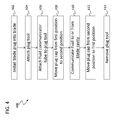
- FIG. 4 an operation 400 for communicating fluid to or from the blade cavity, such as generating a vacuum within a blade cavity, is shown.
- a blade plug is installed within an opening of a blade. When installed on the blade, ambient air is trapped within a cavity of the blade.
- a fluid communicator such as a vacuum tube or pressure tube, may then be attached to a port of the plug tool at step 406.
- the fluid communicator may be operated to communicate fluid to or from a cavity of the plug tool, prior to moving to step 408.
- a vacuum may be formed in a cavity of the plug tool.
- the plug tool is used to move a plug cap from a first position to a second position.
- the fluid communicator is then used to communicate fluid to or from the cavity of the blade, such as pulling air to form a vacuum, through the plug tool, and out the port of the plug tool at step 410.
- the air passes through a first body of the blade plug by means of a passage that passes therethrough, e.g., passage 326 in FIG. 3 .
- the passage fluidly connects an interior side of the plug, i.e., the blade cavity, with an exterior side when a plug cap is in the second, or open, position. When the plug cap is in the first, or closed, position, there is no fluid communication through the passage between the first side and the second side.
- fluid may be communicated into or out of the blade cavity.
- air may be removed from the cavity of the blade and creating or generating a vacuum or near vacuum within the blade.
- fluid such as a gas, may be pumped or communicated into the cavity.
- the plug cap may be moved back to the first, or closed, position by operation of the plug tool at step 412. With the plug cap sealing the blade plug closed, the plug tool 330 may be removed.
- the elements of the blade plug may be formed substantially of aluminum, steel, or other suitable materials.
- Aluminum may be used to provide adequate sealing while maintaining good durability, resistance, and low weight.
- the first and second bodies may be formed of aluminum and the plug cap and fasteners configured to connect the first and second bodies may be formed from steel.
- the threaded portions of the first body may be formed from steel or formed by a steel insert to provide additional strength at the point of threading/unthreading operations.
- a vacuum may be generated within a blade cavity of an aircraft blade.
- the vacuum within the cavity of the blade enables the reduction or removal of stresses that would otherwise be imposed on the blade during operation, particularly at altitude of an aircraft.
- the same process and tool(s) may be used to check air pressure within a blade cavity, as will be appreciated by those of skill in the art.
- the plug tool and blade plug may be formed as an integral piece.
- the first body 302 and the tool body 332 may be integrally formed.
Landscapes
- Engineering & Computer Science (AREA)
- Mechanical Engineering (AREA)
- General Engineering & Computer Science (AREA)
- Aviation & Aerospace Engineering (AREA)
- Pressure Vessels And Lids Thereof (AREA)
Abstract
Description
- Embodiments of the disclosure are directed to methods and devices for communicating fluid into or out of a blade cavity.
- Blades, including aircraft blades, propeller blades, rotor blades, turbine blades, etc., may include an internal cavity that is plugged to prevent hub oil from migrating into the blade during operation. The plug may be installed during manufacture of the blade and, thus, ambient pressure may be locked within the cavity when the blade plug is installed. During manufacturing, ambient air pressure trapped within the blade cavity may be ambient air pressure at ground level. Then, during operation of the blade, i.e., during flight, a differential pressure may exist between the air locked within the blade cavity and the ambient air at altitude. Specifically, the ambient air at altitude may be significantly lower than the air pressure locked or trapped within the blade cavity. This differential pressure may result in stresses imposed on the blade that are added to the normal operating stresses that result from aerodynamic loading on the blade.
- According to one embodiment a method of manufacturing an aircraft blade is provided. The method includes attaching a fluid communicator to a plug tool connected to a blade plug, opening a passage in the blade plug using the plug tool, communicator fluid to or from a blade cavity through the passage using the fluid communicator, and sealing the passage in the blade plug using the plug tool.
- In addition to one or more of the features described above, or as an alternative, further embodiments may include installing the plug tool on the blade plug.
- In addition to one or more of the features described above, or as an alternative, further embodiments may include evacuating air from the plug tool prior to operating the fluid communicator as a vacuum to evacuate air from within a blade.
- In addition to one or more of the features described above, or as an alternative, further embodiments may include wherein the opening of the passage in the blade plug comprises moving a plug cap from a first position to a second position.
- In addition to one or more of the features described above, or as an alternative, further embodiments may include wherein the sealing of the passage in the blade plug comprises moving the plug cap from the second position to the first position.
- In addition to one or more of the features described above, or as an alternative, further embodiments may include installing the blade plug in an opening of a blade.
- In addition to one or more of the features described above, or as an alternative, further embodiments may include checking a pressure within the blade when the passage is open.
- According to another embodiment, a blade plug for an aircraft blade is provided. The blade plug includes a first body having a boss extending therefrom and an aperture passing through the boss, the first body configured to sealingly engage with an opening of a blade, a plug cap configured to releasably engage with the boss and move between a first position and a second position, and a passage passing through the first body configured to allow fluid communication through the first body. When the plug cap is in the first position, fluid may not pass through the passage and, when the plug cap is in the second position, fluid may pass through the passage.
- In addition to one or more of the features described above, or as an alternative, further embodiments may include a second body configured to releasably attach to the first body and form a plug recess between at least a part of the first body and at least a part of the second body.
- In addition to one or more of the features described above, or as an alternative, further embodiments may include at least one fastener configured to releasably attach the second body to the first body.
- In addition to one or more of the features described above, or as an alternative, further embodiments may include a retainer ring configured to engage with the plug recess and configured to provide sealing engagement between the blade plug and a blade.
- According to another embodiment, a plug system for an aircraft blade is provided. The system includes a blade plug having a first body having a boss, an aperture passing through the boss, and a passage passing through the first body configured to allow fluid communication through the first body, a plug cap configured to releasably engage with the boss and move between a first position and a second position, wherein, when the plug cap is in the first position, fluid may not pass through the passage and, when the plug cap is in the second position, fluid may pass through the passage, and a plug tool. The plug tool includes a tool body having a port, the tool body configured to sealingly engage with the boss of the blade plug and an operating portion configured to engage with the plug cap to move the plug cap between the first and second positions.
- In addition to one or more of the features described above, or as an alternative, further embodiments of the blade plug may include a second body configured to releasably attach to the first body and form a plug recess between at least a part of the first body and at least a part of the second body, wherein the first body and the second body are configured to sealing engage with an opening of a blade.
- In addition to one or more of the features described above, or as an alternative, further embodiments may include a fluid communicator connectable to the port of the plug tool to communicate fluid through the passage of the blade plug.
- In addition to one or more of the features described above, or as an alternative, further embodiments may include that the blade plug and the plug tool form an integral body.
- Technical effects of embodiments of the disclosure include a blade plug that is configured to enable fluid communication to or from a blade cavity, resulting in the minimization or elimination of differential pressure stresses experienced by the blade during operation and/or at altitude. Further, technical effects include a process for communicating fluid into or from the blade cavity during manufacture of the blade. Further technical effects include forming a vacuum in the blade cavity during manufacture of the blade.
- The subject matter which is particularly pointed out and distinctly claimed in the claims at the conclusion of the specification. The foregoing and other features and advantages of the disclosure are apparent from the following detailed description taken in conjunction with the accompanying drawings in which:
-
FIG. 1A is a schematic of a blade configured to include a blade plug; -
FIG. 1B is a close-up, cut-away view of the blade and blade plug ofFIG. 1A ; -
FIG. 2 is a perspective view of a blade plug in accordance with an exemplary embodiment of the disclosure; -
FIG. 3 is a side cross-sectional view of a blade plug and plug tool in accordance with an exemplary embodiment of the disclosure; -
FIG. 4 is an operation for communicating fluid to or from a blade cavity in accordance with an exemplary embodiment of the disclosure. -
FIGS. 1A and1B illustrate ablade 100 with ablade plug 102 installed therein. Theblade 100 may be a propeller or other blade used for operating an aircraft. For example,blade 100 may be a propeller blade for a prop plane.FIG. 1B shows a detailed view of anend 110 of theblade 100 where theblade 100 is configured to join with a propeller hub, pitch change actuator, or other driving mechanism of an aircraft. Thus,blade 100 includes a joiningmember 104 configured to engage with a driving mechanism, such as a propeller hub, pitch change actuator, or other driving mechanism. As shown, theblade 100 forms a hollow blade in order to reduce the weight of theblade 100 on an aircraft. Thus,blade 100 defines ablade cavity 106 therein. - The
blade 100 includes anopening 108 at anend 110 proximal to the joiningmember 104. The opening 108 is sealed by theblade plug 102 to lock or seal theblade cavity 106. Theblade plug 102 is configured to prevent oil, air, contaminants, and/or other fluids from entering theblade cavity 106. Thus, theblade plug 102 is configured to sealingly engage with theblade 100 in theopening 108 atend 110. - The
blade plug 102 includes afirst body 112 and asecond body 114, thefirst body 112 configured to sealingly engage with the opening 108 of theblade 100. As shown, thefirst body 112 may be an inner body relative to thecavity 106 and thesecond body 114 may be an outer body relative to thecavity 106. Theblade plug 102 defines a circular shape with an outer circumference that engages with theblade 100 at theopening 108. Thus, the first andsecond bodies opening 108. Afirst aperture 113 may be located in the center of thefirst body 112, and asecond aperture 115 may be located in the center of thesecond body 114. The first andsecond apertures opening 108 of theblade 100. Althoughapertures second bodies - The
blade plug 102 further includes aretaining ring 116 configured to fit between an outer circumference of thefirst body 112 and an outer circumference of thesecond body 114, wherein the outer circumferences define a plug recess formed therebetween. The retainingring 116 is also configured to engage with ablade recess 118 of theend 110 of theblade 100. - To install the
blade plug 102 into theopening 108 of theblade 100, thefirst body 112 is inserted into theopening 108. Then, the retainingring 116 is inserted into theopening 108 and fit within therecess 118. Next, thesecond body 114 is inserted into theopening 108, with thefirst aperture 113 and thesecond aperture 115 aligned. Thefirst body 112 and thesecond body 114 are then releasably engaged and secured to each other by means of afastener 120 that passes through the first andsecond apertures fastener 120 is configured to tighten and hold thefirst body 112 in engagement with thesecond body 114 with the retainingring 116 fitted therebetween. Thus, once thefastener 120 is engaged through the first andsecond apertures blade plug 102 cannot be moved inward or outward relative to theopening 108 and thus the blade plug forms a seal at theopening 108. - The above described installation of the
blade plug 102 is performed during manufacture of theblade 100. Thus, upon completion, thecavity 106 of theblade 100 may be filled with the ambient air that is present during manufacture, i.e., approximately ground level air pressure. As noted above, the pressure differential that may result between the sealed-in air of thecavity 106 and the ambient air during operation may result in increased stresses imposed on theblade 100. - Turning now to
FIG. 2 , ablade plug 200 in accordance with an exemplary embodiment of the disclosure is shown.Blade plug 200 includes afirst body 202 and asecond body 204. As shown, thefirst body 202 forms a solid surface whereas thesecond body 204 forms a ring. This is merely an exemplary and illustrative embodiment, and other configurations are possible without departing from the scope of the disclosure. - A
plug recess 206 is formed between an outer circumference of thefirst body 202 and an out circumference of thesecond body 204. Thefirst body 202 and thesecond body 204 are configured to sealingly engage and/or fit within an opening of a blade, e.g., as shown inFIG. 1 , with a retaining ring (not shown) engaged and held between thefirst body 202 and thesecond body 204 in theplug recess 206, as described above. - The
second body 204 is retained or engaged with thefirst body 202 by a number offasteners 208. As shown, threefasteners 208 are used; however, those of skill in the art will appreciate that any number of fasteners may be employed without departing from the scope of the disclosure. Further, although shown as screws or bolts, other types of fasteners, including mechanical and/or chemical bonds may be used without departing from the scope of the disclosure. - The
first body 202 includes aplug boss 210 extending from the solid surface thereof. When installed on a blade theplug boss 210 is configured to extend away from a blade cavity. Aplug cap 212 is configured to sealingly engage with theplug boss 210. Theplug cap 212 removably and releasably engages with theplug boss 210 to provide a seal therebetween. Theplug cap 212 includes anengagement mechanism 214. As shown, theengagement mechanism 214 is a hex-shaped recess in a top of theplug cap 212 and is configured to allow a tool to engage with theplug cap 212 for release or removal of theplug cap 212 from theplug boss 210, and for installation into theplug boss 210. Advantageously, as explained below, theplug cap 212 allows for fluid communication through theblade plug 200 to the blade cavity, when theblade plug 200 is installed and sealingly secured within an opening of a blade. For example, such access enables generation of a vacuum within the blade cavity, thus reducing the internal stresses that may result from pressure differentials when ambient air is locked or trapped within the blade cavity. Alternatively, such access enables fluid to be communicated into the blade cavity to increase the pressure. - Turning now to
FIG. 3 , a cross-sectional side view of ablade plug 300 with aplug tool 330 attached thereto in accordance with an exemplary embodiment of the disclosure is shown. Features ofblade plug 300 may be substantially similar to features ofblade plug 200 ofFIG. 2 , and thus like features are labeled with similar reference numerals except preceded by a "3" rather than a "2." -
Blade plug 300 includes afirst body 302 and asecond body 304. Aplug recess 306 if formed between an outer diameter of thefirst body 302 and an outer diameter of thesecond body 304. Retained between the first andsecond bodies plug recess 306 is a retainingring 307. Thefirst body 302 and thesecond body 304 are held together by one or more fasteners (not shown) as described above. Aplug boss 310 extends from thefirst body 302, e.g., upward inFIG. 3 . Anaperture 311 passes through the center of theplug boss 310. In some embodiments, and as shown inFIG. 3 , theaperture 311 may be threaded in order to threadedly engage with a threaded portion of aplug cap 312. Theplug cap 312 may include anengagement mechanism 314 therein, as described above. In alternative embodiments,aperture 311 may include a separate threaded insert. In some such embodiments, the threaded insert may be formed from the same or a different material from the rest of thefirst body 302. - The
plug cap 312 includes afirst portion 316 and asecond portion 318. Thefirst portion 316 may be a top or cap to theplug cap 312. The first portion may define anengagement surface 317 that is configured to engage with a top or exterior surface of theplug boss 310, as shown. Further, thefirst portion 316 of theplug cap 312 defines theengagement mechanism 314. Thefirst portion 316 also includes acap seal 320 on theengagement surface 317.Cap seal 320 is configured to sealing engage between theengagement surface 317 of thefirst portion 316 of theplug cap 312 and a top surface of theplug boss 310, as shown. - The
second portion 318 of theplug cap 312 is configured to engage with theaperture 311 in theplug boss 310 of thefirst body 302. In some embodiments, such as when theaperture 311 is threaded or incorporates a threaded insert, thesecond portion 318 may be also threaded. Those of skill in the art will appreciate that other types of connections and engagements may be used without departing from the scope of the disclosure. - The
second portion 318 of theplug cap 312 is configured to enable theplug cap 312 to move, actuate, slide, etc. between a first position and a second position. In the first position (shown inFIG. 3 ), theplug cap 312 is fully engaged with theplug boss 310. That is, theengagement surface 317, thecap seal 320, and the top surface of theplug boss 310 form a sealed engagement therebetween. Thus, the first position may be referred to as a closed position. - The
plug cap 312 may then be operated such that it moves to a second position that is at least partially disengaged from theplug boss 310. For example, in some embodiments, the first position may be when the second portion is fully, threadedly engaged with threads of theaperture 311 of theplug boss 310 or the threaded insert withinaperture 311. In the second position, theplug cap 312 may be moved upward inFIG. 3 , such that thecap seal 320 no longer forms a complete seal between theengagement surface 317 of theplug cap 312 and theplug boss 310. That is, in some embodiments, the second position may be defined by partial or complete unthreading of thesecond portion 318 from theplug boss 310. - In the second position, fluid, such as air, may be able to flow between a
first side 322 of theblade plug 300 to asecond side 324 of theblade plug 300. For example, thefirst side 322 may be a blade cavity or blade interior and thesecond side 324 may be exterior to the blade cavity, see, for reference,FIG. 1 . In the first position, fluid may not be able to pass from thefirst side 322 to thesecond side 324, or in the other direction, due to theplug cap 312 and thecap seal 320. However, when theplug cap 312 is in the second position, thecap seal 320 is not in contact with theengagement surface 317 of theplug boss 310, and thus air may be able to pass through theblade plug 300. To enable this, apassage 326 is configured to fluidly connect thefirst side 322 with thesecond side 324. In some embodiments,passage 326 may be a hole that passes through thefirst body 302. Thus, the second position may be referred to as an open position. - Also shown in
FIG. 3 is aplug tool 330 configured to enable generation of a vacuum or near-vacuum in a blade cavity by extraction or evacuation of air through theblade plug 300. Alternatively, theplug tool 330 can be configured to increase pressure within a blade cavity by injecting fluid, such as gas, through theblade plug 300. Thus, theplug tool 330 is configured to control fluid communication to and from the blade cavity through theblade plug 300. - The
plug tool 330 includes atool body 332 and an operatingportion 334. Thetool body 332 defines atool cavity 336 with portions of thetool body 332 configured to sealingly engage with an exterior surface of theplug boss 310 and/or with a surface of thefirst body 302. As shown, the seal between thetool body 332 and theplug boss 310 is formed, in part, byfirst tool seal 338 which sealingly fits between thetool body 332 and an exterior surface of theplug boss 310. - The
tool body 332 also includes or defines aport 340 that fluidly connects thesecond side 324 and thetool cavity 336. When thefirst tool seal 338 is engaged with theplug boss 310, theport 340 provides the only fluid communication between thesecond side 324 and thetool cavity 336. - Extending into the
tool cavity 336 is a portion of the operatingportion 334. The operatingportion 334 is configured to engage with theengagement mechanism 314 of theplug cap 312 and to move theplug cap 312 from the first position to the second position and from the second position to the first position. Asecond tool seal 342 provides a seal between the operatingportion 334 and thetool body 332 such that fluids, such as air, cannot pass between the two parts (332, 334) of the plug tool. - Turning now to
FIG. 4 , anoperation 400 for communicating fluid to or from the blade cavity, such as generating a vacuum within a blade cavity, is shown. Atstep 402, a blade plug is installed within an opening of a blade. When installed on the blade, ambient air is trapped within a cavity of the blade. To remove the air from the blade cavity, a plug tool is attached to the blade plug atstep 404. A fluid communicator, such as a vacuum tube or pressure tube, may then be attached to a port of the plug tool atstep 406. In some embodiments, as part ofstep 406, the fluid communicator may be operated to communicate fluid to or from a cavity of the plug tool, prior to moving to step 408. For example, atstep 406, a vacuum may be formed in a cavity of the plug tool. - At
step 408, the plug tool is used to move a plug cap from a first position to a second position. The fluid communicator is then used to communicate fluid to or from the cavity of the blade, such as pulling air to form a vacuum, through the plug tool, and out the port of the plug tool atstep 410. - The air passes through a first body of the blade plug by means of a passage that passes therethrough, e.g.,
passage 326 inFIG. 3 . The passage fluidly connects an interior side of the plug, i.e., the blade cavity, with an exterior side when a plug cap is in the second, or open, position. When the plug cap is in the first, or closed, position, there is no fluid communication through the passage between the first side and the second side. - Thus, at
step 410, fluid may be communicated into or out of the blade cavity. For example, air may be removed from the cavity of the blade and creating or generating a vacuum or near vacuum within the blade. Alternatively, fluid, such as a gas, may be pumped or communicated into the cavity. After the fluid is communicated into or out of the blade cavity, the plug cap may be moved back to the first, or closed, position by operation of the plug tool atstep 412. With the plug cap sealing the blade plug closed, theplug tool 330 may be removed. - Although a specific order of steps has been described above and shown in
FIG. 4 , those of skill in the art will appreciate that the order provided is not the only way to achieve forming a vacuum or increasing pressure in a blade by use of a blade plug and plug tool as described herein. Thus, theoperation 400 is provided merely for illustrative and explanatory purposes and the disclosure is not limited thereby. Further, as noted, although described with respect to forming a vacuum, those of skill in the art will appreciate that the process described herein may be used to inject fluid or increase pressure within a blade cavity. - In some embodiments the elements of the blade plug may be formed substantially of aluminum, steel, or other suitable materials. Aluminum may be used to provide adequate sealing while maintaining good durability, resistance, and low weight. In some embodiments, the first and second bodies may be formed of aluminum and the plug cap and fasteners configured to connect the first and second bodies may be formed from steel. Further, in some embodiments, the threaded portions of the first body may be formed from steel or formed by a steel insert to provide additional strength at the point of threading/unthreading operations.
- Advantageously, embodiments disclosed herein provide for communication of fluid through a blade plug during manufacture of the blade. Thus, in accordance with some embodiments disclosed herein, a vacuum may be generated within a blade cavity of an aircraft blade. The vacuum within the cavity of the blade enables the reduction or removal of stresses that would otherwise be imposed on the blade during operation, particularly at altitude of an aircraft.
- Further, advantageously, there is no additional imposition during manufacture of a blade for part of the assembly to be made or formed in a vacuum or near-vacuum environment. As such, relatively minor changes may be made to current manufacturing operations while taking advantage of embodiments of the disclosure, i.e., vacuum formation within a blade cavity.
- While the disclosure has been described in detail in connection with only a limited number of embodiments, it should be readily understood that the disclosure is not limited to such disclosed embodiments. Rather, embodiments of the disclosure can be modified to incorporate any number of variations, alterations, substitutions, combination, sub-combination, or equivalent arrangements not heretofore described, but which are commensurate with the spirit and scope of the disclosure. Additionally, while various embodiments of the disclosure have been described, it is to be understood that aspects of the disclosure may include only some of the described embodiments.
- For example, although described herein as a means of generating a vacuum or increasing pressure within a blade, the same process and tool(s) may be used to check air pressure within a blade cavity, as will be appreciated by those of skill in the art. Further, although some exemplary dimensions, materials, shapes, configurations, etc. are shown and described, those of skill in the art will appreciate that other dimensions, materials, shapes, configurations, etc. may be used without departing from the scope of the disclosure. Further, in some embodiments, the plug tool and blade plug may be formed as an integral piece. For example, with reference to
FIG. 3 , thefirst body 302 and thetool body 332 may be integrally formed. - Accordingly, the disclosure is not to be seen as limited by the foregoing description, but is only limited by the scope of the appended claims.
Claims (11)
- A method of manufacturing an aircraft blade comprising:attaching a fluid communicator to a plug tool connected to a blade plug;opening a passage in the blade plug using the plug tool;communicating fluid to or from a blade cavity through the passage using the fluid
communicator; andsealing the passage in the blade plug using the plug tool. - The method of claim 1, further comprising installing the plug tool on the blade plug.
- The method of claim 1 or 2, further comprising evacuating air from the plug tool prior to operating the fluid communicator as a vacuum to evacuate air from within a blade.
- The method of claim 1, 2 or 3, wherein opening the passage in the blade plug comprises moving a plug cap from a first position to a second position.
- The method of claim 4, wherein sealing the passage in the blade plug comprises moving the plug cap from the second position to the first position.
- The method of any preceding claim, further comprising installing the blade plug in an opening of a blade.
- The method of any preceding claim, further comprising checking a pressure within the blade when the passage is open.
- A blade plug for an aircraft blade, the blade plug comprising:a first body having a boss extending therefrom and an aperture passing through the boss, the first body configured to sealingly engage with an opening of a blade;a plug cap configured to releasably engage with the boss and move between a first position and a second position; anda passage passing through the first body configured to allow fluid communication through the first body,wherein, when the plug cap is in the first position, fluid may not pass through the passage and, when the plug cap is in the second position, fluid may pass through the passage.
- The blade plug of claim 8, further comprising a second body configured to releasably attach to the first body and form a plug recess between at least a part of the first body and at least a part of the second body.
- The blade plug of claim 9, further comprising at least one fastener configured to releasably attach the second body to the first body.
- The blade plug of claim 8, 9 or 10, further comprising a retainer ring configured to engage with the plug recess and configured to provide sealing engagement between the blade plug and a blade.
Priority Applications (2)
| Application Number | Priority Date | Filing Date | Title |
|---|---|---|---|
| EP15305650.2A EP3088298B1 (en) | 2015-04-28 | 2015-04-28 | Blade plug for communicating fluid therethrough |
| US15/131,621 US10464660B2 (en) | 2015-04-28 | 2016-04-18 | Blade plug for communicating fluid therethrough |
Applications Claiming Priority (1)
| Application Number | Priority Date | Filing Date | Title |
|---|---|---|---|
| EP15305650.2A EP3088298B1 (en) | 2015-04-28 | 2015-04-28 | Blade plug for communicating fluid therethrough |
Publications (2)
| Publication Number | Publication Date |
|---|---|
| EP3088298A1 true EP3088298A1 (en) | 2016-11-02 |
| EP3088298B1 EP3088298B1 (en) | 2017-12-13 |
Family
ID=53040485
Family Applications (1)
| Application Number | Title | Priority Date | Filing Date |
|---|---|---|---|
| EP15305650.2A Active EP3088298B1 (en) | 2015-04-28 | 2015-04-28 | Blade plug for communicating fluid therethrough |
Country Status (2)
| Country | Link |
|---|---|
| US (1) | US10464660B2 (en) |
| EP (1) | EP3088298B1 (en) |
Families Citing this family (1)
| Publication number | Priority date | Publication date | Assignee | Title |
|---|---|---|---|---|
| US12203412B2 (en) | 2022-06-10 | 2025-01-21 | Rtx Corporation | Turbine engine shaft plug |
Citations (4)
| Publication number | Priority date | Publication date | Assignee | Title |
|---|---|---|---|---|
| CH235185A (en) * | 1942-07-14 | 1944-11-15 | Messerschmitt Boelkow Blohm | Hollow blade for propellers. |
| US2405022A (en) * | 1943-08-21 | 1946-07-30 | Curtiss Wright Corp | Propeller blade |
| EP0171492A1 (en) * | 1984-02-29 | 1986-02-19 | F.B.M.- HUDSON ITALIANA S.p.A. | Low noise hollow fan blade and process |
| DE10341058B3 (en) * | 2003-09-03 | 2004-11-25 | N.V. Vasco | Venting head for central heating radiator has screw bung fitted with rotational valve body controlling connection between axial bore and venting channel |
Family Cites Families (1)
| Publication number | Priority date | Publication date | Assignee | Title |
|---|---|---|---|---|
| US3667862A (en) * | 1970-12-09 | 1972-06-06 | Boeing Co | Blade inspection system and method |
-
2015
- 2015-04-28 EP EP15305650.2A patent/EP3088298B1/en active Active
-
2016
- 2016-04-18 US US15/131,621 patent/US10464660B2/en active Active
Patent Citations (4)
| Publication number | Priority date | Publication date | Assignee | Title |
|---|---|---|---|---|
| CH235185A (en) * | 1942-07-14 | 1944-11-15 | Messerschmitt Boelkow Blohm | Hollow blade for propellers. |
| US2405022A (en) * | 1943-08-21 | 1946-07-30 | Curtiss Wright Corp | Propeller blade |
| EP0171492A1 (en) * | 1984-02-29 | 1986-02-19 | F.B.M.- HUDSON ITALIANA S.p.A. | Low noise hollow fan blade and process |
| DE10341058B3 (en) * | 2003-09-03 | 2004-11-25 | N.V. Vasco | Venting head for central heating radiator has screw bung fitted with rotational valve body controlling connection between axial bore and venting channel |
Also Published As
| Publication number | Publication date |
|---|---|
| EP3088298B1 (en) | 2017-12-13 |
| US20160318598A1 (en) | 2016-11-03 |
| US10464660B2 (en) | 2019-11-05 |
Similar Documents
| Publication | Publication Date | Title |
|---|---|---|
| US10533448B2 (en) | Borescope plug for gas turbine engine | |
| EP3450694A3 (en) | Flow path assemblies for gas turbine engines and assembly methods therefore | |
| US9541151B2 (en) | Dual stage shock strut with removable second stage fluid chamber | |
| CN113366229B (en) | Spark suppressing cap | |
| EP2851521A1 (en) | Air turbine starter including a lightweight, low differential pressure check valve | |
| US20220380019A1 (en) | Duct stringer assembly with bulkhead | |
| CN104482280B (en) | A kind of water discharge method of aircraft air-tight cabin | |
| US10704667B2 (en) | Vented gear spline lubrication | |
| CN103256410A (en) | Refrigeration system and ball valve thereof | |
| CN105916659A (en) | Insert and method of attaching insert to structure | |
| US10464660B2 (en) | Blade plug for communicating fluid therethrough | |
| US20140131999A1 (en) | Claw quick disconnect intercom fitting | |
| US10407158B2 (en) | Blade plug for communicating fluid therethrough | |
| CN109649630B (en) | Convenient quick aerating device of airship gasbag | |
| CN108709728B (en) | Centrifugal ventilator performance test device | |
| EP2943712B1 (en) | Lever quick connect intercom fitting | |
| CN110281203A (en) | A kind of normal pressure changes alloy cutter sealing device maintenance replacement tooling and application method | |
| US20170159796A1 (en) | Vented gear spline lubrication | |
| EP2977564A1 (en) | Bleed valve assembly with resonator chamber | |
| CN108910016A (en) | Quick Release wing and unmanned vehicle | |
| CN103754390A (en) | Ram air parachute and chordwise chain type closing method thereof | |
| US10293930B2 (en) | Spar end cap with drain hole provisions | |
| JP4366600B2 (en) | Emergency release fitting | |
| CN210510326U (en) | Control valve capable of realizing manual pressure relief and manual emergency closing | |
| US20140260956A1 (en) | Circumferential sealing of piston assembly in a piston actuator |
Legal Events
| Date | Code | Title | Description |
|---|---|---|---|
| PUAI | Public reference made under article 153(3) epc to a published international application that has entered the european phase |
Free format text: ORIGINAL CODE: 0009012 |
|
| AK | Designated contracting states |
Kind code of ref document: A1 Designated state(s): AL AT BE BG CH CY CZ DE DK EE ES FI FR GB GR HR HU IE IS IT LI LT LU LV MC MK MT NL NO PL PT RO RS SE SI SK SM TR |
|
| AX | Request for extension of the european patent |
Extension state: BA ME |
|
| 17P | Request for examination filed |
Effective date: 20170427 |
|
| RBV | Designated contracting states (corrected) |
Designated state(s): AL AT BE BG CH CY CZ DE DK EE ES FI FR GB GR HR HU IE IS IT LI LT LU LV MC MK MT NL NO PL PT RO RS SE SI SK SM TR |
|
| STAA | Information on the status of an ep patent application or granted ep patent |
Free format text: STATUS: REQUEST FOR EXAMINATION WAS MADE |
|
| RIC1 | Information provided on ipc code assigned before grant |
Ipc: F04D 27/02 20060101ALI20170517BHEP Ipc: F04D 29/32 20060101ALI20170517BHEP Ipc: F01D 5/14 20060101ALI20170517BHEP Ipc: B64C 11/24 20060101AFI20170517BHEP Ipc: F01D 5/18 20060101ALI20170517BHEP |
|
| GRAP | Despatch of communication of intention to grant a patent |
Free format text: ORIGINAL CODE: EPIDOSNIGR1 |
|
| STAA | Information on the status of an ep patent application or granted ep patent |
Free format text: STATUS: GRANT OF PATENT IS INTENDED |
|
| INTG | Intention to grant announced |
Effective date: 20170627 |
|
| GRAS | Grant fee paid |
Free format text: ORIGINAL CODE: EPIDOSNIGR3 |
|
| GRAA | (expected) grant |
Free format text: ORIGINAL CODE: 0009210 |
|
| STAA | Information on the status of an ep patent application or granted ep patent |
Free format text: STATUS: THE PATENT HAS BEEN GRANTED |
|
| REG | Reference to a national code |
Ref country code: GB Ref legal event code: FG4D |
|
| REG | Reference to a national code |
Ref country code: AT Ref legal event code: REF Ref document number: 954100 Country of ref document: AT Kind code of ref document: T Effective date: 20171215 Ref country code: CH Ref legal event code: EP |
|
| REG | Reference to a national code |
Ref country code: IE Ref legal event code: FG4D |
|
| REG | Reference to a national code |
Ref country code: DE Ref legal event code: R096 Ref document number: 602015006646 Country of ref document: DE |
|
| REG | Reference to a national code |
Ref country code: FR Ref legal event code: PLFP Year of fee payment: 4 |
|
| REG | Reference to a national code |
Ref country code: NL Ref legal event code: MP Effective date: 20171213 |
|
| PG25 | Lapsed in a contracting state [announced via postgrant information from national office to epo] |
Ref country code: FI Free format text: LAPSE BECAUSE OF FAILURE TO SUBMIT A TRANSLATION OF THE DESCRIPTION OR TO PAY THE FEE WITHIN THE PRESCRIBED TIME-LIMIT Effective date: 20171213 Ref country code: NO Free format text: LAPSE BECAUSE OF FAILURE TO SUBMIT A TRANSLATION OF THE DESCRIPTION OR TO PAY THE FEE WITHIN THE PRESCRIBED TIME-LIMIT Effective date: 20180313 Ref country code: SE Free format text: LAPSE BECAUSE OF FAILURE TO SUBMIT A TRANSLATION OF THE DESCRIPTION OR TO PAY THE FEE WITHIN THE PRESCRIBED TIME-LIMIT Effective date: 20171213 |
|
| REG | Reference to a national code |
Ref country code: AT Ref legal event code: MK05 Ref document number: 954100 Country of ref document: AT Kind code of ref document: T Effective date: 20171213 |
|
| PG25 | Lapsed in a contracting state [announced via postgrant information from national office to epo] |
Ref country code: BG Free format text: LAPSE BECAUSE OF FAILURE TO SUBMIT A TRANSLATION OF THE DESCRIPTION OR TO PAY THE FEE WITHIN THE PRESCRIBED TIME-LIMIT Effective date: 20180313 Ref country code: HR Free format text: LAPSE BECAUSE OF FAILURE TO SUBMIT A TRANSLATION OF THE DESCRIPTION OR TO PAY THE FEE WITHIN THE PRESCRIBED TIME-LIMIT Effective date: 20171213 Ref country code: GR Free format text: LAPSE BECAUSE OF FAILURE TO SUBMIT A TRANSLATION OF THE DESCRIPTION OR TO PAY THE FEE WITHIN THE PRESCRIBED TIME-LIMIT Effective date: 20180314 Ref country code: LV Free format text: LAPSE BECAUSE OF FAILURE TO SUBMIT A TRANSLATION OF THE DESCRIPTION OR TO PAY THE FEE WITHIN THE PRESCRIBED TIME-LIMIT Effective date: 20171213 Ref country code: RS Free format text: LAPSE BECAUSE OF FAILURE TO SUBMIT A TRANSLATION OF THE DESCRIPTION OR TO PAY THE FEE WITHIN THE PRESCRIBED TIME-LIMIT Effective date: 20171213 |
|
| PG25 | Lapsed in a contracting state [announced via postgrant information from national office to epo] |
Ref country code: NL Free format text: LAPSE BECAUSE OF FAILURE TO SUBMIT A TRANSLATION OF THE DESCRIPTION OR TO PAY THE FEE WITHIN THE PRESCRIBED TIME-LIMIT Effective date: 20171213 |
|
| PG25 | Lapsed in a contracting state [announced via postgrant information from national office to epo] |
Ref country code: CY Free format text: LAPSE BECAUSE OF FAILURE TO SUBMIT A TRANSLATION OF THE DESCRIPTION OR TO PAY THE FEE WITHIN THE PRESCRIBED TIME-LIMIT Effective date: 20171213 Ref country code: EE Free format text: LAPSE BECAUSE OF FAILURE TO SUBMIT A TRANSLATION OF THE DESCRIPTION OR TO PAY THE FEE WITHIN THE PRESCRIBED TIME-LIMIT Effective date: 20171213 Ref country code: CZ Free format text: LAPSE BECAUSE OF FAILURE TO SUBMIT A TRANSLATION OF THE DESCRIPTION OR TO PAY THE FEE WITHIN THE PRESCRIBED TIME-LIMIT Effective date: 20171213 Ref country code: ES Free format text: LAPSE BECAUSE OF FAILURE TO SUBMIT A TRANSLATION OF THE DESCRIPTION OR TO PAY THE FEE WITHIN THE PRESCRIBED TIME-LIMIT Effective date: 20171213 Ref country code: SK Free format text: LAPSE BECAUSE OF FAILURE TO SUBMIT A TRANSLATION OF THE DESCRIPTION OR TO PAY THE FEE WITHIN THE PRESCRIBED TIME-LIMIT Effective date: 20171213 |
|
| PG25 | Lapsed in a contracting state [announced via postgrant information from national office to epo] |
Ref country code: SM Free format text: LAPSE BECAUSE OF FAILURE TO SUBMIT A TRANSLATION OF THE DESCRIPTION OR TO PAY THE FEE WITHIN THE PRESCRIBED TIME-LIMIT Effective date: 20171213 Ref country code: PL Free format text: LAPSE BECAUSE OF FAILURE TO SUBMIT A TRANSLATION OF THE DESCRIPTION OR TO PAY THE FEE WITHIN THE PRESCRIBED TIME-LIMIT Effective date: 20171213 Ref country code: AT Free format text: LAPSE BECAUSE OF FAILURE TO SUBMIT A TRANSLATION OF THE DESCRIPTION OR TO PAY THE FEE WITHIN THE PRESCRIBED TIME-LIMIT Effective date: 20171213 Ref country code: IS Free format text: LAPSE BECAUSE OF FAILURE TO SUBMIT A TRANSLATION OF THE DESCRIPTION OR TO PAY THE FEE WITHIN THE PRESCRIBED TIME-LIMIT Effective date: 20180413 Ref country code: RO Free format text: LAPSE BECAUSE OF FAILURE TO SUBMIT A TRANSLATION OF THE DESCRIPTION OR TO PAY THE FEE WITHIN THE PRESCRIBED TIME-LIMIT Effective date: 20171213 Ref country code: IT Free format text: LAPSE BECAUSE OF FAILURE TO SUBMIT A TRANSLATION OF THE DESCRIPTION OR TO PAY THE FEE WITHIN THE PRESCRIBED TIME-LIMIT Effective date: 20171213 |
|
| REG | Reference to a national code |
Ref country code: DE Ref legal event code: R097 Ref document number: 602015006646 Country of ref document: DE |
|
| PLBE | No opposition filed within time limit |
Free format text: ORIGINAL CODE: 0009261 |
|
| STAA | Information on the status of an ep patent application or granted ep patent |
Free format text: STATUS: NO OPPOSITION FILED WITHIN TIME LIMIT |
|
| REG | Reference to a national code |
Ref country code: DE Ref legal event code: R119 Ref document number: 602015006646 Country of ref document: DE |
|
| 26N | No opposition filed |
Effective date: 20180914 |
|
| PG25 | Lapsed in a contracting state [announced via postgrant information from national office to epo] |
Ref country code: DK Free format text: LAPSE BECAUSE OF FAILURE TO SUBMIT A TRANSLATION OF THE DESCRIPTION OR TO PAY THE FEE WITHIN THE PRESCRIBED TIME-LIMIT Effective date: 20171213 Ref country code: MC Free format text: LAPSE BECAUSE OF FAILURE TO SUBMIT A TRANSLATION OF THE DESCRIPTION OR TO PAY THE FEE WITHIN THE PRESCRIBED TIME-LIMIT Effective date: 20171213 |
|
| REG | Reference to a national code |
Ref country code: CH Ref legal event code: PL |
|
| REG | Reference to a national code |
Ref country code: BE Ref legal event code: MM Effective date: 20180430 |
|
| REG | Reference to a national code |
Ref country code: IE Ref legal event code: MM4A |
|
| PG25 | Lapsed in a contracting state [announced via postgrant information from national office to epo] |
Ref country code: DE Free format text: LAPSE BECAUSE OF NON-PAYMENT OF DUE FEES Effective date: 20181101 Ref country code: LU Free format text: LAPSE BECAUSE OF NON-PAYMENT OF DUE FEES Effective date: 20180428 |
|
| PG25 | Lapsed in a contracting state [announced via postgrant information from national office to epo] |
Ref country code: SI Free format text: LAPSE BECAUSE OF FAILURE TO SUBMIT A TRANSLATION OF THE DESCRIPTION OR TO PAY THE FEE WITHIN THE PRESCRIBED TIME-LIMIT Effective date: 20171213 Ref country code: LI Free format text: LAPSE BECAUSE OF NON-PAYMENT OF DUE FEES Effective date: 20180430 Ref country code: BE Free format text: LAPSE BECAUSE OF NON-PAYMENT OF DUE FEES Effective date: 20180430 Ref country code: CH Free format text: LAPSE BECAUSE OF NON-PAYMENT OF DUE FEES Effective date: 20180430 |
|
| PG25 | Lapsed in a contracting state [announced via postgrant information from national office to epo] |
Ref country code: IE Free format text: LAPSE BECAUSE OF NON-PAYMENT OF DUE FEES Effective date: 20180428 |
|
| PG25 | Lapsed in a contracting state [announced via postgrant information from national office to epo] |
Ref country code: MT Free format text: LAPSE BECAUSE OF NON-PAYMENT OF DUE FEES Effective date: 20180428 |
|
| PG25 | Lapsed in a contracting state [announced via postgrant information from national office to epo] |
Ref country code: TR Free format text: LAPSE BECAUSE OF FAILURE TO SUBMIT A TRANSLATION OF THE DESCRIPTION OR TO PAY THE FEE WITHIN THE PRESCRIBED TIME-LIMIT Effective date: 20171213 |
|
| PG25 | Lapsed in a contracting state [announced via postgrant information from national office to epo] |
Ref country code: PT Free format text: LAPSE BECAUSE OF FAILURE TO SUBMIT A TRANSLATION OF THE DESCRIPTION OR TO PAY THE FEE WITHIN THE PRESCRIBED TIME-LIMIT Effective date: 20171213 |
|
| PG25 | Lapsed in a contracting state [announced via postgrant information from national office to epo] |
Ref country code: MK Free format text: LAPSE BECAUSE OF NON-PAYMENT OF DUE FEES Effective date: 20171213 Ref country code: HU Free format text: LAPSE BECAUSE OF FAILURE TO SUBMIT A TRANSLATION OF THE DESCRIPTION OR TO PAY THE FEE WITHIN THE PRESCRIBED TIME-LIMIT; INVALID AB INITIO Effective date: 20150428 Ref country code: LT Free format text: LAPSE BECAUSE OF FAILURE TO SUBMIT A TRANSLATION OF THE DESCRIPTION OR TO PAY THE FEE WITHIN THE PRESCRIBED TIME-LIMIT Effective date: 20171213 |
|
| PG25 | Lapsed in a contracting state [announced via postgrant information from national office to epo] |
Ref country code: AL Free format text: LAPSE BECAUSE OF FAILURE TO SUBMIT A TRANSLATION OF THE DESCRIPTION OR TO PAY THE FEE WITHIN THE PRESCRIBED TIME-LIMIT Effective date: 20171213 |
|
| P01 | Opt-out of the competence of the unified patent court (upc) registered |
Free format text: CASE NUMBER: UPC_APP_0019537_3088298/2025 Effective date: 20251228 |
|
| PGFP | Annual fee paid to national office [announced via postgrant information from national office to epo] |
Ref country code: GB Payment date: 20260319 Year of fee payment: 12 |
|
| PGFP | Annual fee paid to national office [announced via postgrant information from national office to epo] |
Ref country code: FR Payment date: 20260320 Year of fee payment: 12 |