EP3088145B1 - Shaver, shaver cutting mesh and process for manufacturing shaver cutting mesh - Google Patents
Shaver, shaver cutting mesh and process for manufacturing shaver cutting mesh Download PDFInfo
- Publication number
- EP3088145B1 EP3088145B1 EP14874411.3A EP14874411A EP3088145B1 EP 3088145 B1 EP3088145 B1 EP 3088145B1 EP 14874411 A EP14874411 A EP 14874411A EP 3088145 B1 EP3088145 B1 EP 3088145B1
- Authority
- EP
- European Patent Office
- Prior art keywords
- mesh
- shaver
- cutting
- cutting mesh
- manufacturing
- Prior art date
- Legal status (The legal status is an assumption and is not a legal conclusion. Google has not performed a legal analysis and makes no representation as to the accuracy of the status listed.)
- Active
Links
- 238000005520 cutting process Methods 0.000 claims description 101
- 238000000034 method Methods 0.000 claims description 28
- 230000008569 process Effects 0.000 claims description 28
- 238000004519 manufacturing process Methods 0.000 claims description 24
- 238000003466 welding Methods 0.000 claims description 19
- 239000002184 metal Substances 0.000 claims description 15
- 238000010438 heat treatment Methods 0.000 claims description 7
- 239000000463 material Substances 0.000 claims description 4
- 238000004080 punching Methods 0.000 claims description 4
- 230000005540 biological transmission Effects 0.000 claims description 2
- 238000005530 etching Methods 0.000 claims description 2
- 230000007246 mechanism Effects 0.000 claims description 2
- 229910001220 stainless steel Inorganic materials 0.000 claims 2
- 239000010935 stainless steel Substances 0.000 claims 2
- 238000005868 electrolysis reaction Methods 0.000 claims 1
- 238000003754 machining Methods 0.000 description 9
- 230000000694 effects Effects 0.000 description 3
- 230000002411 adverse Effects 0.000 description 2
- 230000009286 beneficial effect Effects 0.000 description 2
- 238000003825 pressing Methods 0.000 description 2
- 230000009471 action Effects 0.000 description 1
- 238000010923 batch production Methods 0.000 description 1
- 230000008901 benefit Effects 0.000 description 1
- 230000007547 defect Effects 0.000 description 1
- 238000010586 diagram Methods 0.000 description 1
- 230000006872 improvement Effects 0.000 description 1
- 238000005259 measurement Methods 0.000 description 1
- 238000002844 melting Methods 0.000 description 1
- 230000008018 melting Effects 0.000 description 1
- 238000009987 spinning Methods 0.000 description 1
Images
Classifications
-
- B—PERFORMING OPERATIONS; TRANSPORTING
- B26—HAND CUTTING TOOLS; CUTTING; SEVERING
- B26B—HAND-HELD CUTTING TOOLS NOT OTHERWISE PROVIDED FOR
- B26B19/00—Clippers or shavers operating with a plurality of cutting edges, e.g. hair clippers, dry shavers
- B26B19/14—Clippers or shavers operating with a plurality of cutting edges, e.g. hair clippers, dry shavers of the rotary-cutter type; Cutting heads therefor; Cutters therefor
- B26B19/143—Details of outer cutters
-
- B—PERFORMING OPERATIONS; TRANSPORTING
- B26—HAND CUTTING TOOLS; CUTTING; SEVERING
- B26B—HAND-HELD CUTTING TOOLS NOT OTHERWISE PROVIDED FOR
- B26B19/00—Clippers or shavers operating with a plurality of cutting edges, e.g. hair clippers, dry shavers
- B26B19/38—Details of, or accessories for, hair clippers, or dry shavers, e.g. housings, casings, grips, guards
- B26B19/3893—Manufacturing of shavers or clippers or components thereof
Definitions
- the invention relates to a process for manufacturing a shaver cutting mesh according to the preamble of claim 1.
- the invention relates to a shaver, a shaver cutting mesh, and a process for manufacturing the shaver cutting mesh.
- a process for manufacturing a shaver cutting mesh is known, for example, from FR 56 021 E .
- CN 203 019 397 U discloses a mesh enclosure of a shaver.
- the mesh enclosure comprises a mesh enclosure body connected with a shaver body and a blade arranged in the mesh enclosure, wherein the mesh enclosure body comprises a mesh enclosure surface and a circular mesh enclosure seat; mesh holes through which beard can pass are fully formed in the mesh enclosure surface; the upper end of the mesh enclosure seat is connected with the mesh enclosure surface; the lower end of the mesh enclosure seat is fixedly connected with the shaver body; and the blade is arranged in a space formed by the mesh enclosure surface and the mesh enclosure seat.
- the mesh enclosure of a tool bit of the shaver is divided into the mesh enclosure surface and the mesh enclosure seat connected with the mesh enclosure surface, so that the mesh enclosure is convenient to produce, assemble and replace, simple in structure and easy to process; and the consumption cost is saved.
- the rotary electric shaver head according to WO 2013/056512 A1 comprises a cutter mesh cover having a wavy curved surface.
- the cutter mesh cover is provided with a C-shaped or an S-shaped beard feeding hole slot.
- the beard feeding hole slot is a combination of a round hole and a slot, or a combination of a long slot and a short slot.
- a movable cutter is fixed on a drive connection member through hot-press melting to form a movable cutter assembly.
- the movable cutter assembly is driven through the contact of an upper conical surface of a conical surface drive shaft and an inner conical surface of a drive shaft sleeve.
- the movable cutter assembly is arranged on a boss at an inner surface of an elastic cutter seat.
- the movable cutter assembly contacts only the boss at the inner surface of the elastic cutter seat when spinning.
- the elastic cutter seat applies an upward pressing force to the movable cutter assembly, and is connected to the cutter mesh cover. Under the action of the pressing force, the movable cutter assembly closely contacts an inner surface of the cutter mesh cover.
- the rotary electric shaver head solves the problems of beard gripping, beard pulling, poor sharpness, and poor shaving sound quality, and can capture the human face skin contour, so as to provide more efficient, comfortable and complete shaving experience.
- the electric shavers are divided into reciprocating type circle razors and rotary type shavers.
- a cutting mesh of a rotary type shaver is a thin-wall and shallow-groove part.
- the thickness of a mesh surface is required to reach 0.1mm uniformly, because only the mesh surface with the thicknesses of 0.1mm can ensure not only comfort degree but also cleanness when used for shaving.
- a cutting mesh structure in a plane form appeared earlier, and the cutting mesh is manufactured with the following steps: punching the whole of a metal sheet with a thickness being 0.5mm to obtain a blank, machining mesh slots, then performing heat treatment, and then performing cutting and grinding on cutting mesh parts in batches.
- a mesh surface meets the requirement of uniform thickness being 0.1 mm, and a housing at the lower part also has a relatively big thickness.
- a surface contacted with the skin has a plane structure, general equipment is much, and the measurement is relatively easy, so that the process in a batch production course can be monitored more easily.
- the cutting mesh structure in the plane form has the advantage that the mesh surface in a plane has an ideal effect for short beards. The disadvantage is that the ability of capturing long beards performs poorly, a user easily feels pulling in beards and the skin feeling is poor.
- the cutting mesh with the arc surface is manufactured with the following steps: punching the whole of a material with a thickness being 0.5mm to obtain a blank, machining mesh slots, then performing heat treatment, and adopting special equipment for independent cutting and grinding, so as to enable the whole mesh surface to meet the requirement of desired thickness being 0.1mm, and a housing at the lower part to have a relatively big thickness.
- the mesh surface made in this way can reach the thickness of 0.1mm only in one certain point, so that it is difficult to enable the whole arc surface to reach the thickness of 0.1mm by adopting the manufacturing process.
- the cutting mesh behaves relatively well in the ability of capturing both long and short beards, and the skin feeling is good.
- the arc surface is difficult to manufacture, high in production cost, and not ideal in effect, which is adverse to the development of the industry.
- the invention provides a shaver according to claim 13, a shaver cutting mesh, and a process for manufacturing the shaver cutting mesh according to claim 1 with further embodiments described in claims 2 to 12, and mainly solves the problem that the cutting mesh with an arc surface in the prior art is difficult to manufacture, high in production cost, and not ideal in effect, which is adverse to the development of the industry.
- a shaver cutting mesh comprises a cutting mesh surface and a cutting mesh housing, a plurality of mesh slots are formed in the cutting mesh surface, the lower part of the cutting mesh surface extends to form a welding portion, the cutting mesh housing is a circular ring, a clamp ring is integrally formed on an edge at the lower part of the cutting mesh housing, and the cutting mesh surface is arranged at the upper part of the cutting mesh housing in a sleeving manner and is welded with the cutting mesh housing by the welding portion.
- a blade locater is welded at the center of the cutting mesh surface, and is arranged on the inner surface of the cutting mesh surface.
- the cutting mesh housing is provided with a circular groove matched with the welding portion.
- the invention has the beneficial effects that an integral drawing process is not adopted, the cutting mesh is divided into two parts to be machined, and then the two parts are combined together by adopting a welding process, so that the mesh surface part is good in uniformity, the radian of the whole mesh surface also can be ensured, the comfort degree and the cleanness in shaving are further improved, and the housing part is machined at a thickness (such as 0.5mm) larger than that of the mesh surface part to ensure the strength of a whole mesh cover.
- a shaver cutting mesh comprises a cutting mesh surface 1 and a cutting mesh housing 2, a plurality of mesh slots 5 are formed in the cutting mesh surface 1, the lower part of the cutting mesh surface 1 extends to form a welding portion 11, the cutting mesh housing 2 is a circular ring, a clamp ring 4 is integrally formed on an edge at the lower part of the cutting mesh housing 2, and the cutting mesh surface 1 is arranged at the upper part of the cutting mesh housing 2 in a sleeving manner and is welded with the cutting mesh housing 2 by the welding portion 11.
- a blade locater 6 is welded at the center of the cutting mesh surface 1, and is arranged on the inner surface of the cutting mesh surface 1. The blade locater is used for mounting a rotary blade.
- the cutting mesh housing 2 is provided with a circular groove 3 matched with the welding portion 11.
- the shaver cutting mesh has good suitability and is convenient to mount and match.
- a shaver comprises a housing, a power supply, an electric motor, and shaving components controlled by a transmission mechanism, and the shaver is provided with the shaver cutting mesh. Because of an arc surface structure, the cutting mesh behaves relatively well in the ability of capturing both long and short beards, and the skin feeling is good.
- a process for manufacturing a shaver cutting mesh comprises the following steps: preparing a metal sheet with a thickness being 0.1mm and a metal sheet with a thickness being 0.5mm; forming mesh slots 5 in the metal sheet with the thickness being 0.1mm by cutting and machining; drawing the metal sheet with the machined mesh slots to form a cutting mesh surface 1 and extending an edge of the cutting mesh surface 1 to form a welding portion 11; manufacturing an arc surface on the cutting mesh surface 1 by adopting a male die of a die to shallowly stretch the middle part of the metal sheet with the machined mesh slots; after drawing the cutting mesh surface, welding a blade locater 6 at the center of the inner surface of the cutting mesh surface 1; stretching the metal sheet with the thickness being 0.5mm to form a cutting mesh housing 2 which is a circular ring, machining the cutting mesh housing 2 to form a circular groove 3 matched with the welding portion 11, and forming a clamp ring 4 on an edge at the lower part of the cutting mesh housing 2; welding the cutting mesh surface 1 with the cutting mesh housing
- the step of machining mesh slots can be put after the step of welding the cutting mesh surface 1 with the cutting mesh housing 2, and then the mesh slots are machined on the cutting mesh surface 1.
- the mesh slots also can be machined by adopting an etching process, an electrolytic machining process, a punching machining process or the like.
- the machining precision is high, and the yield is high.
- the invention has the beneficial effects that an integral drawing process is not adopted, the cutting mesh is divided into two parts to be machined, and then the two parts are completely combined together by adopting a welding process, so that the mesh surface part is good in uniformity, the radian of the whole mesh surface also can be ensured, the comfort degree and the cleanness in shaving are further improved, and the housing part is machined at a thickness (such as 0.5mm) larger than that of the mesh surface part to ensure the strength of a whole mesh cover.
Landscapes
- Engineering & Computer Science (AREA)
- Life Sciences & Earth Sciences (AREA)
- Forests & Forestry (AREA)
- Mechanical Engineering (AREA)
- Manufacturing & Machinery (AREA)
- Dry Shavers And Clippers (AREA)
- Wire Processing (AREA)
Description
- The invention relates to a process for manufacturing a shaver cutting mesh according to the preamble of claim 1. In particular, the invention relates to a shaver, a shaver cutting mesh, and a process for manufacturing the shaver cutting mesh.
- A process for manufacturing a shaver cutting mesh is known, for example, from
FR 56 021 E - Further,
CN 203 019 397 U discloses a mesh enclosure of a shaver. The mesh enclosure comprises a mesh enclosure body connected with a shaver body and a blade arranged in the mesh enclosure, wherein the mesh enclosure body comprises a mesh enclosure surface and a circular mesh enclosure seat; mesh holes through which beard can pass are fully formed in the mesh enclosure surface; the upper end of the mesh enclosure seat is connected with the mesh enclosure surface; the lower end of the mesh enclosure seat is fixedly connected with the shaver body; and the blade is arranged in a space formed by the mesh enclosure surface and the mesh enclosure seat. The mesh enclosure of a tool bit of the shaver is divided into the mesh enclosure surface and the mesh enclosure seat connected with the mesh enclosure surface, so that the mesh enclosure is convenient to produce, assemble and replace, simple in structure and easy to process; and the consumption cost is saved. - Further, the rotary electric shaver head according to
WO 2013/056512 A1 comprises a cutter mesh cover having a wavy curved surface. The cutter mesh cover is provided with a C-shaped or an S-shaped beard feeding hole slot. The beard feeding hole slot is a combination of a round hole and a slot, or a combination of a long slot and a short slot. A movable cutter is fixed on a drive connection member through hot-press melting to form a movable cutter assembly. The movable cutter assembly is driven through the contact of an upper conical surface of a conical surface drive shaft and an inner conical surface of a drive shaft sleeve. The movable cutter assembly is arranged on a boss at an inner surface of an elastic cutter seat. The movable cutter assembly contacts only the boss at the inner surface of the elastic cutter seat when spinning. The elastic cutter seat applies an upward pressing force to the movable cutter assembly, and is connected to the cutter mesh cover. Under the action of the pressing force, the movable cutter assembly closely contacts an inner surface of the cutter mesh cover. The rotary electric shaver head solves the problems of beard gripping, beard pulling, poor sharpness, and poor shaving sound quality, and can capture the human face skin contour, so as to provide more efficient, comfortable and complete shaving experience. - There are various shaver products in the current market, and two main types are manual razor blades and electric shavers. The electric shavers are divided into reciprocating type circle razors and rotary type shavers.
- Due to relatively good adaptability, the rotary type shavers become more and more popular in the market. With the constant development of the electric shavers, machining of cutting meshes becomes an urgent subject for improvement and research in the current industry. A cutting mesh of a rotary type shaver is a thin-wall and shallow-groove part. The thickness of a mesh surface is required to reach 0.1mm uniformly, because only the mesh surface with the thicknesses of 0.1mm can ensure not only comfort degree but also cleanness when used for shaving.
- A cutting mesh structure in a plane form appeared earlier, and the cutting mesh is manufactured with the following steps: punching the whole of a metal sheet with a thickness being 0.5mm to obtain a blank, machining mesh slots, then performing heat treatment, and then performing cutting and grinding on cutting mesh parts in batches. A mesh surface meets the requirement of uniform thickness being 0.1 mm, and a housing at the lower part also has a relatively big thickness. A surface contacted with the skin has a plane structure, general equipment is much, and the measurement is relatively easy, so that the process in a batch production course can be monitored more easily. The cutting mesh structure in the plane form has the advantage that the mesh surface in a plane has an ideal effect for short beards. The disadvantage is that the ability of capturing long beards performs poorly, a user easily feels pulling in beards and the skin feeling is poor.
- Later, a cutting mesh structure in an arc surface form appeared, and the cutting mesh with the arc surface is manufactured with the following steps: punching the whole of a material with a thickness being 0.5mm to obtain a blank, machining mesh slots, then performing heat treatment, and adopting special equipment for independent cutting and grinding, so as to enable the whole mesh surface to meet the requirement of desired thickness being 0.1mm, and a housing at the lower part to have a relatively big thickness. However, the mesh surface made in this way can reach the thickness of 0.1mm only in one certain point, so that it is difficult to enable the whole arc surface to reach the thickness of 0.1mm by adopting the manufacturing process. Because of the arc surface structure, the cutting mesh behaves relatively well in the ability of capturing both long and short beards, and the skin feeling is good. However, the arc surface is difficult to manufacture, high in production cost, and not ideal in effect, which is adverse to the development of the industry.
- In order to overcome defects in the background art, the invention provides a shaver according to claim 13, a shaver cutting mesh, and a process for manufacturing the shaver cutting mesh according to claim 1 with further embodiments described in
claims 2 to 12, and mainly solves the problem that the cutting mesh with an arc surface in the prior art is difficult to manufacture, high in production cost, and not ideal in effect, which is adverse to the development of the industry. - The invention adopts a technical scheme: a shaver cutting mesh comprises a cutting mesh surface and a cutting mesh housing, a plurality of mesh slots are formed in the cutting mesh surface, the lower part of the cutting mesh surface extends to form a welding portion, the cutting mesh housing is a circular ring, a clamp ring is integrally formed on an edge at the lower part of the cutting mesh housing, and the cutting mesh surface is arranged at the upper part of the cutting mesh housing in a sleeving manner and is welded with the cutting mesh housing by the welding portion.
- A blade locater is welded at the center of the cutting mesh surface, and is arranged on the inner surface of the cutting mesh surface.
- The cutting mesh housing is provided with a circular groove matched with the welding portion.
- The invention has the beneficial effects that an integral drawing process is not adopted, the cutting mesh is divided into two parts to be machined, and then the two parts are combined together by adopting a welding process, so that the mesh surface part is good in uniformity, the radian of the whole mesh surface also can be ensured, the comfort degree and the cleanness in shaving are further improved, and the housing part is machined at a thickness (such as 0.5mm) larger than that of the mesh surface part to ensure the strength of a whole mesh cover.
-
-
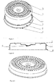
Figure 1 is an exploded view of a shaver cutting mesh. -
Figure 2 is a sectional view of a shaver cutting mesh. -
Figure 3 is a stereogram of a shaver cutting mesh. -
Figure 4 is a structural schematic diagram of a shaver cutting mesh. - In the
figures, 1 - cutting mesh surface, 11 - welding portion, 2 - cutting mesh housing, 3 - circular groove, 4 - clamp ring, 5 - mesh slot, 6 - blade locater - Embodiments of the invention are further described as follows with reference to the drawings:
As shown inFigure 1 combined withFigures 2-4 , a shaver cutting mesh comprises a cutting mesh surface 1 and acutting mesh housing 2, a plurality ofmesh slots 5 are formed in the cutting mesh surface 1, the lower part of the cutting mesh surface 1 extends to form awelding portion 11, thecutting mesh housing 2 is a circular ring, aclamp ring 4 is integrally formed on an edge at the lower part of thecutting mesh housing 2, and the cutting mesh surface 1 is arranged at the upper part of thecutting mesh housing 2 in a sleeving manner and is welded with thecutting mesh housing 2 by thewelding portion 11. Ablade locater 6 is welded at the center of the cutting mesh surface 1, and is arranged on the inner surface of the cutting mesh surface 1. The blade locater is used for mounting a rotary blade. - The
cutting mesh housing 2 is provided with acircular groove 3 matched with thewelding portion 11. The shaver cutting mesh has good suitability and is convenient to mount and match. - A shaver comprises a housing, a power supply, an electric motor, and shaving components controlled by a transmission mechanism, and the shaver is provided with the shaver cutting mesh. Because of an arc surface structure, the cutting mesh behaves relatively well in the ability of capturing both long and short beards, and the skin feeling is good.
- A process for manufacturing a shaver cutting mesh comprises the following steps: preparing a metal sheet with a thickness being 0.1mm and a metal sheet with a thickness being 0.5mm; forming
mesh slots 5 in the metal sheet with the thickness being 0.1mm by cutting and machining; drawing the metal sheet with the machined mesh slots to form a cutting mesh surface 1 and extending an edge of the cutting mesh surface 1 to form awelding portion 11; manufacturing an arc surface on the cutting mesh surface 1 by adopting a male die of a die to shallowly stretch the middle part of the metal sheet with the machined mesh slots; after drawing the cutting mesh surface, welding ablade locater 6 at the center of the inner surface of the cutting mesh surface 1; stretching the metal sheet with the thickness being 0.5mm to form acutting mesh housing 2 which is a circular ring, machining thecutting mesh housing 2 to form acircular groove 3 matched with thewelding portion 11, and forming aclamp ring 4 on an edge at the lower part of thecutting mesh housing 2; welding the cutting mesh surface 1 with thecutting mesh housing 2; performing heat treatment for the cutting mesh surface 1 and thecutting mesh housing 2; removing burrs after completing the heat treatment. - In the embodiment, the step of machining mesh slots can be put after the step of welding the cutting mesh surface 1 with the
cutting mesh housing 2, and then the mesh slots are machined on the cutting mesh surface 1. - In the embodiment, the mesh slots also can be machined by adopting an etching process, an electrolytic machining process, a punching machining process or the like. The machining precision is high, and the yield is high.
- The invention has the beneficial effects that an integral drawing process is not adopted, the cutting mesh is divided into two parts to be machined, and then the two parts are completely combined together by adopting a welding process, so that the mesh surface part is good in uniformity, the radian of the whole mesh surface also can be ensured, the comfort degree and the cleanness in shaving are further improved, and the housing part is machined at a thickness (such as 0.5mm) larger than that of the mesh surface part to ensure the strength of a whole mesh cover.
Claims (13)
- A process for manufacturing a shaver cutting mesh, comprising the following steps: a, material selection: preparing a metal sheet I with a first thickness and a metal sheet II with a second thickness; b, cutting mesh surface drawing: drawing the metal sheet I to form a cutting mesh surface (1) and extending an edge of the cutting mesh surface (1) to form a welding portion (11); c, cutting mesh housing stretching: stretching the metal sheet II to form a cutting mesh housing (2) which is a circular ring, and forming a clamp ring (4) on an edge at the lower part of the cutting mesh housing (2); d, welding: welding the cutting mesh surface (1) with the cutting mesh housing (2); e, heat treatment, the process being further characterized in that a blade locater (6) is welded at the center of the inner surface of the cutting mesh surface (1) after the cutting mesh surface is drawn and before the cutting mesh housing is stretched.
- The process for manufacturing a shaver cutting mesh of claim 1, wherein the metal sheet I is machined to form mesh slots (5) before the cutting mesh surface is drawn.
- The process for manufacturing a shaver cutting mesh of claim 1, wherein the cutting mesh surface (1) is machined to form mesh slots (5) after welding and before heat treatment.
- The process for manufacturing a shaver cutting mesh of claim 2 or 3, wherein the mesh slots (5) are machined and made by adopting a cutting process.
- The process for manufacturing a shaver cutting mesh of claim 2 or 3, wherein the mesh slots (5) are machined and made by adopting an etching process.
- The process for manufacturing a shaver cutting mesh of claim 2 or 3, wherein the mesh slots (5) are machined and made by adopting an electrolysis process.
- The process for manufacturing a shaver cutting mesh of claim 2 or 3, wherein the mesh slots (5) are machined and made by adopting a punching process.
- The process for manufacturing a shaver cutting mesh of claim 1, wherein burrs are removed after the heat treatment is completed.
- The process for manufacturing a shaver cutting mesh of claim 1, wherein an arc surface is manufactured on the cutting mesh surface (1) by adopting a male die of a die to shallowly stretch the middle part of the metal sheet I.
- The process for manufacturing a shaver cutting mesh of claim 1, wherein a circular groove (3) matched with the welding portion (11) is machined on the cutting mesh housing (2).
- The process for manufacturing a shaver cutting mesh of claim 1, wherein the metal sheet I is made of a stainless steel material, and the thickness is 0.1mm.
- The process for manufacturing a shaver cutting mesh of claim 1, wherein the metal sheet II is made of a stainless steel material, and the thickness is 0.5mm.
- A shaver, comprising a housing, a power supply, an electric motor, and shaving components controlled by a transmission mechanism, wherein the shaver is provided with a shaver cutting mesh that is manufactured following the manufacturing process set forth in claim 1.
Applications Claiming Priority (2)
| Application Number | Priority Date | Filing Date | Title |
|---|---|---|---|
| CN201310714564 | 2013-12-23 | ||
| PCT/CN2014/072021 WO2015096276A1 (en) | 2013-12-23 | 2014-02-13 | Shaver, shaver cutting mesh and process for manufacturing shaver cutting mesh |
Publications (3)
| Publication Number | Publication Date |
|---|---|
| EP3088145A1 EP3088145A1 (en) | 2016-11-02 |
| EP3088145A4 EP3088145A4 (en) | 2017-10-11 |
| EP3088145B1 true EP3088145B1 (en) | 2019-05-01 |
Family
ID=50521003
Family Applications (1)
| Application Number | Title | Priority Date | Filing Date |
|---|---|---|---|
| EP14874411.3A Active EP3088145B1 (en) | 2013-12-23 | 2014-02-13 | Shaver, shaver cutting mesh and process for manufacturing shaver cutting mesh |
Country Status (5)
| Country | Link |
|---|---|
| US (1) | US9676109B2 (en) |
| EP (1) | EP3088145B1 (en) |
| JP (1) | JP2017500909A (en) |
| CN (1) | CN103753608B (en) |
| WO (1) | WO2015096276A1 (en) |
Families Citing this family (9)
| Publication number | Priority date | Publication date | Assignee | Title |
|---|---|---|---|---|
| US9737545B2 (en) | 2013-12-19 | 2017-08-22 | Merck Sharp & Dohme Corp. | HIV protease inhibitors |
| CN103753608B (en) * | 2013-12-23 | 2016-08-17 | 温州朗威电器有限公司 | Shaver and shaver cutter net and the manufacturing process of shaver cutter net |
| US20170217030A1 (en) * | 2016-02-02 | 2017-08-03 | Izumi Products Company | Rotary electric shaver and method of manufacturing outer blade of rotary electric shaver |
| CN108068144B (en) * | 2016-11-11 | 2023-08-22 | 浙江超人科技股份有限公司 | Processing method of anti-separation circular knife assembly of electric shaver |
| CN107584522B (en) * | 2017-10-24 | 2024-02-06 | 焕醒科技(杭州)有限公司 | Electric shaver convenient to assemble |
| EP3736092A1 (en) * | 2019-05-08 | 2020-11-11 | Koninklijke Philips N.V. | Method of manufacturing a guard element for use in a hair-cutting unit |
| EP3895856A1 (en) * | 2020-04-14 | 2021-10-20 | Koninklijke Philips N.V. | Reducing sound production in a hair-cutting unit comprising an external cutting member and a rotatable internal cutting member |
| CN116460435B (en) * | 2023-04-08 | 2025-09-09 | 余姚市人杰电器有限公司 | Full-automatic razor blade welding machine |
| CN116551175B (en) * | 2023-07-11 | 2023-11-28 | 张家港市美安金属制品科技有限公司 | Automatic processing system for eyebrow trimming blade |
Citations (1)
| Publication number | Priority date | Publication date | Assignee | Title |
|---|---|---|---|---|
| WO2013056512A1 (en) * | 2011-10-18 | 2013-04-25 | 上海奔腾电工有限公司 | Rotary electric shaver head |
Family Cites Families (25)
| Publication number | Priority date | Publication date | Assignee | Title |
|---|---|---|---|---|
| US2341833A (en) * | 1941-09-29 | 1944-02-15 | Chris L Volz | Shaving device |
| FR56021E (en) * | 1945-08-02 | 1952-09-11 | Electric razor improvements | |
| GB1056038A (en) * | 1963-11-06 | 1967-01-25 | Philips Electronic Associated | Improvements in or relating to methods of manufacturing curved metal bodies provided with apertures |
| US3881373A (en) * | 1974-03-13 | 1975-05-06 | Matsushita Electric Works Ltd | Method of making outer blade for electric shaver |
| JPS602069B2 (en) | 1976-09-14 | 1985-01-18 | 松下電工株式会社 | Inner blade of rotary electric shaver |
| JPS615868A (en) * | 1984-06-20 | 1986-01-11 | 松下電工株式会社 | Outer blade of electric razor |
| JPS61125372A (en) * | 1984-11-21 | 1986-06-13 | 松下電工株式会社 | Electric razor blade |
| JPH1033853A (en) | 1996-07-22 | 1998-02-10 | Matsushita Electric Works Ltd | Rotary type electric razor |
| CN2480119Y (en) | 2001-06-13 | 2002-03-06 | 包成华 | Net hood for rotary razor |
| US20030070304A1 (en) * | 2001-10-15 | 2003-04-17 | Zachary Curello | Cutting foil for rotary shavers and manufacturing methods for producing same |
| CN2647519Y (en) * | 2003-06-17 | 2004-10-13 | 上海真博电器有限公司 | Four-head double-directional electric shaver |
| CN2721304Y (en) * | 2004-01-18 | 2005-08-31 | 超人集团有限公司 | Non-nickel stainless steel netting sheet production line |
| CN100577348C (en) * | 2004-01-18 | 2010-01-06 | 超人集团有限公司 | A kind of manufacturing method of mesh sheet for razor |
| JP2005230238A (en) * | 2004-02-19 | 2005-09-02 | Izumi Products Co | Electric razor |
| CN200970785Y (en) * | 2006-11-21 | 2007-11-07 | 童志荣 | Screen of shaver |
| CN101254596B (en) | 2008-02-20 | 2010-07-14 | 浙江金达电机电器有限公司 | Double-edge tool bit of multiheaded rotary electric shaver |
| KR200457537Y1 (en) * | 2009-04-22 | 2011-12-22 | 오태준 | Split electric razor-net of electric razor |
| CN202155897U (en) | 2011-07-07 | 2012-03-07 | 浙江光科电器有限公司 | Shaver net structure |
| CN202147287U (en) | 2011-07-15 | 2012-02-22 | 浙江金达电机电器有限公司 | Stationary knife of multi-head rotary electric shaver |
| CN102259144B (en) * | 2011-07-15 | 2013-06-19 | 浙江金达电机电器有限公司 | Manufacture method for shim of multi-head rotary electric shaver |
| JP2014198059A (en) | 2011-08-09 | 2014-10-23 | 株式会社泉精器製作所 | Method of producing outer blade of rotary shaver and outer blade |
| CN102366962B (en) * | 2011-10-18 | 2014-11-12 | 上海奔腾电工有限公司 | Tool bit for rotary electric shaver |
| CN203019397U (en) * | 2013-01-18 | 2013-06-26 | 温州市庆东五金制品有限公司 | Mesh enclosure of shaver |
| CN203680340U (en) * | 2013-12-23 | 2014-07-02 | 温州朗威电器有限公司 | Blade net of shaver |
| CN103753608B (en) | 2013-12-23 | 2016-08-17 | 温州朗威电器有限公司 | Shaver and shaver cutter net and the manufacturing process of shaver cutter net |
-
2014
- 2014-02-08 CN CN201410045589.7A patent/CN103753608B/en active Active
- 2014-02-13 EP EP14874411.3A patent/EP3088145B1/en active Active
- 2014-02-13 WO PCT/CN2014/072021 patent/WO2015096276A1/en not_active Ceased
- 2014-02-13 US US15/107,082 patent/US9676109B2/en not_active Expired - Fee Related
- 2014-02-13 JP JP2016530167A patent/JP2017500909A/en active Pending
Patent Citations (2)
| Publication number | Priority date | Publication date | Assignee | Title |
|---|---|---|---|---|
| WO2013056512A1 (en) * | 2011-10-18 | 2013-04-25 | 上海奔腾电工有限公司 | Rotary electric shaver head |
| US20150082637A1 (en) * | 2011-10-18 | 2015-03-26 | Shanghai Povos Electric Works Co., Ltd. | Rotary electric shaver head |
Also Published As
| Publication number | Publication date |
|---|---|
| WO2015096276A1 (en) | 2015-07-02 |
| EP3088145A4 (en) | 2017-10-11 |
| US9676109B2 (en) | 2017-06-13 |
| CN103753608B (en) | 2016-08-17 |
| JP2017500909A (en) | 2017-01-12 |
| CN103753608A (en) | 2014-04-30 |
| US20170028575A1 (en) | 2017-02-02 |
| EP3088145A1 (en) | 2016-11-02 |
Similar Documents
| Publication | Publication Date | Title |
|---|---|---|
| EP3088145B1 (en) | Shaver, shaver cutting mesh and process for manufacturing shaver cutting mesh | |
| WO2013056512A1 (en) | Rotary electric shaver head | |
| WO2009036593A1 (en) | A external cutter structure of reciprocating electric shaver and the method of making the same | |
| JP2017500909A5 (en) | ||
| CN100371145C (en) | Inner cutter of reciprocating electric shaver and manufacturing method thereof | |
| CN203495989U (en) | Novel shaver cutter head structure | |
| CN212684032U (en) | Shaver head and shaver | |
| CN102366962B (en) | Tool bit for rotary electric shaver | |
| CN217703512U (en) | Static blade | |
| CN202278590U (en) | Rotary type electric shaver head | |
| CN203460205U (en) | Rotary shaver | |
| CN107000228B (en) | Razor head, razor net and manufacturing process method of razor net | |
| CN104339963A (en) | Microscopic carving method for making fine pattern die by adopting metal material | |
| CN217595612U (en) | Processing device for spring coil notch | |
| CN216781909U (en) | Shaver head with pre-hair-stretching function and reciprocating shaver | |
| CN203680340U (en) | Blade net of shaver | |
| CN215328436U (en) | A kind of electrolytic forming mould of shaver net cover | |
| CN210336035U (en) | Shaver convenient to change tool bit | |
| CN204295709U (en) | A kind of rotary electric shaver cutter net | |
| CN203471809U (en) | Rotary-type double-ring convex-cambered-surface electric shaver head | |
| CN204295710U (en) | A kind of rotary electric shaver shaver head assembly | |
| CN209774725U (en) | Personal care trimmer | |
| CN210100071U (en) | Shaving apparatus | |
| CN211615689U (en) | Shaving device | |
| CN213829071U (en) | Multifunctional cutter mesh suitable for spherical shaver and plush trimmer |
Legal Events
| Date | Code | Title | Description |
|---|---|---|---|
| PUAI | Public reference made under article 153(3) epc to a published international application that has entered the european phase |
Free format text: ORIGINAL CODE: 0009012 |
|
| 17P | Request for examination filed |
Effective date: 20160705 |
|
| AK | Designated contracting states |
Kind code of ref document: A1 Designated state(s): AL AT BE BG CH CY CZ DE DK EE ES FI FR GB GR HR HU IE IS IT LI LT LU LV MC MK MT NL NO PL PT RO RS SE SI SK SM TR |
|
| AX | Request for extension of the european patent |
Extension state: BA ME |
|
| DAX | Request for extension of the european patent (deleted) | ||
| A4 | Supplementary search report drawn up and despatched |
Effective date: 20170911 |
|
| RIC1 | Information provided on ipc code assigned before grant |
Ipc: B26B 19/38 20060101ALI20170905BHEP Ipc: B26B 19/14 20060101AFI20170905BHEP |
|
| STAA | Information on the status of an ep patent application or granted ep patent |
Free format text: STATUS: EXAMINATION IS IN PROGRESS |
|
| 17Q | First examination report despatched |
Effective date: 20180820 |
|
| GRAP | Despatch of communication of intention to grant a patent |
Free format text: ORIGINAL CODE: EPIDOSNIGR1 |
|
| STAA | Information on the status of an ep patent application or granted ep patent |
Free format text: STATUS: GRANT OF PATENT IS INTENDED |
|
| INTG | Intention to grant announced |
Effective date: 20190125 |
|
| GRAS | Grant fee paid |
Free format text: ORIGINAL CODE: EPIDOSNIGR3 |
|
| GRAA | (expected) grant |
Free format text: ORIGINAL CODE: 0009210 |
|
| STAA | Information on the status of an ep patent application or granted ep patent |
Free format text: STATUS: THE PATENT HAS BEEN GRANTED |
|
| AK | Designated contracting states |
Kind code of ref document: B1 Designated state(s): AL AT BE BG CH CY CZ DE DK EE ES FI FR GB GR HR HU IE IS IT LI LT LU LV MC MK MT NL NO PL PT RO RS SE SI SK SM TR |
|
| REG | Reference to a national code |
Ref country code: GB Ref legal event code: FG4D |
|
| REG | Reference to a national code |
Ref country code: CH Ref legal event code: EP Ref country code: AT Ref legal event code: REF Ref document number: 1126306 Country of ref document: AT Kind code of ref document: T Effective date: 20190515 |
|
| REG | Reference to a national code |
Ref country code: DE Ref legal event code: R096 Ref document number: 602014046012 Country of ref document: DE |
|
| REG | Reference to a national code |
Ref country code: IE Ref legal event code: FG4D |
|
| REG | Reference to a national code |
Ref country code: NL Ref legal event code: MP Effective date: 20190501 |
|
| REG | Reference to a national code |
Ref country code: LT Ref legal event code: MG4D |
|
| PG25 | Lapsed in a contracting state [announced via postgrant information from national office to epo] |
Ref country code: SE Free format text: LAPSE BECAUSE OF FAILURE TO SUBMIT A TRANSLATION OF THE DESCRIPTION OR TO PAY THE FEE WITHIN THE PRESCRIBED TIME-LIMIT Effective date: 20190501 Ref country code: NL Free format text: LAPSE BECAUSE OF FAILURE TO SUBMIT A TRANSLATION OF THE DESCRIPTION OR TO PAY THE FEE WITHIN THE PRESCRIBED TIME-LIMIT Effective date: 20190501 Ref country code: ES Free format text: LAPSE BECAUSE OF FAILURE TO SUBMIT A TRANSLATION OF THE DESCRIPTION OR TO PAY THE FEE WITHIN THE PRESCRIBED TIME-LIMIT Effective date: 20190501 Ref country code: HR Free format text: LAPSE BECAUSE OF FAILURE TO SUBMIT A TRANSLATION OF THE DESCRIPTION OR TO PAY THE FEE WITHIN THE PRESCRIBED TIME-LIMIT Effective date: 20190501 Ref country code: AL Free format text: LAPSE BECAUSE OF FAILURE TO SUBMIT A TRANSLATION OF THE DESCRIPTION OR TO PAY THE FEE WITHIN THE PRESCRIBED TIME-LIMIT Effective date: 20190501 Ref country code: PT Free format text: LAPSE BECAUSE OF FAILURE TO SUBMIT A TRANSLATION OF THE DESCRIPTION OR TO PAY THE FEE WITHIN THE PRESCRIBED TIME-LIMIT Effective date: 20190901 Ref country code: NO Free format text: LAPSE BECAUSE OF FAILURE TO SUBMIT A TRANSLATION OF THE DESCRIPTION OR TO PAY THE FEE WITHIN THE PRESCRIBED TIME-LIMIT Effective date: 20190801 Ref country code: FI Free format text: LAPSE BECAUSE OF FAILURE TO SUBMIT A TRANSLATION OF THE DESCRIPTION OR TO PAY THE FEE WITHIN THE PRESCRIBED TIME-LIMIT Effective date: 20190501 Ref country code: LT Free format text: LAPSE BECAUSE OF FAILURE TO SUBMIT A TRANSLATION OF THE DESCRIPTION OR TO PAY THE FEE WITHIN THE PRESCRIBED TIME-LIMIT Effective date: 20190501 |
|
| PG25 | Lapsed in a contracting state [announced via postgrant information from national office to epo] |
Ref country code: GR Free format text: LAPSE BECAUSE OF FAILURE TO SUBMIT A TRANSLATION OF THE DESCRIPTION OR TO PAY THE FEE WITHIN THE PRESCRIBED TIME-LIMIT Effective date: 20190802 Ref country code: LV Free format text: LAPSE BECAUSE OF FAILURE TO SUBMIT A TRANSLATION OF THE DESCRIPTION OR TO PAY THE FEE WITHIN THE PRESCRIBED TIME-LIMIT Effective date: 20190501 Ref country code: RS Free format text: LAPSE BECAUSE OF FAILURE TO SUBMIT A TRANSLATION OF THE DESCRIPTION OR TO PAY THE FEE WITHIN THE PRESCRIBED TIME-LIMIT Effective date: 20190501 Ref country code: BG Free format text: LAPSE BECAUSE OF FAILURE TO SUBMIT A TRANSLATION OF THE DESCRIPTION OR TO PAY THE FEE WITHIN THE PRESCRIBED TIME-LIMIT Effective date: 20190801 |
|
| REG | Reference to a national code |
Ref country code: AT Ref legal event code: MK05 Ref document number: 1126306 Country of ref document: AT Kind code of ref document: T Effective date: 20190501 |
|
| PG25 | Lapsed in a contracting state [announced via postgrant information from national office to epo] |
Ref country code: IS Free format text: LAPSE BECAUSE OF FAILURE TO SUBMIT A TRANSLATION OF THE DESCRIPTION OR TO PAY THE FEE WITHIN THE PRESCRIBED TIME-LIMIT Effective date: 20190901 |
|
| PG25 | Lapsed in a contracting state [announced via postgrant information from national office to epo] |
Ref country code: DK Free format text: LAPSE BECAUSE OF FAILURE TO SUBMIT A TRANSLATION OF THE DESCRIPTION OR TO PAY THE FEE WITHIN THE PRESCRIBED TIME-LIMIT Effective date: 20190501 Ref country code: EE Free format text: LAPSE BECAUSE OF FAILURE TO SUBMIT A TRANSLATION OF THE DESCRIPTION OR TO PAY THE FEE WITHIN THE PRESCRIBED TIME-LIMIT Effective date: 20190501 Ref country code: AT Free format text: LAPSE BECAUSE OF FAILURE TO SUBMIT A TRANSLATION OF THE DESCRIPTION OR TO PAY THE FEE WITHIN THE PRESCRIBED TIME-LIMIT Effective date: 20190501 Ref country code: RO Free format text: LAPSE BECAUSE OF FAILURE TO SUBMIT A TRANSLATION OF THE DESCRIPTION OR TO PAY THE FEE WITHIN THE PRESCRIBED TIME-LIMIT Effective date: 20190501 Ref country code: SK Free format text: LAPSE BECAUSE OF FAILURE TO SUBMIT A TRANSLATION OF THE DESCRIPTION OR TO PAY THE FEE WITHIN THE PRESCRIBED TIME-LIMIT Effective date: 20190501 Ref country code: CZ Free format text: LAPSE BECAUSE OF FAILURE TO SUBMIT A TRANSLATION OF THE DESCRIPTION OR TO PAY THE FEE WITHIN THE PRESCRIBED TIME-LIMIT Effective date: 20190501 |
|
| REG | Reference to a national code |
Ref country code: DE Ref legal event code: R097 Ref document number: 602014046012 Country of ref document: DE |
|
| PG25 | Lapsed in a contracting state [announced via postgrant information from national office to epo] |
Ref country code: IT Free format text: LAPSE BECAUSE OF FAILURE TO SUBMIT A TRANSLATION OF THE DESCRIPTION OR TO PAY THE FEE WITHIN THE PRESCRIBED TIME-LIMIT Effective date: 20190501 Ref country code: SM Free format text: LAPSE BECAUSE OF FAILURE TO SUBMIT A TRANSLATION OF THE DESCRIPTION OR TO PAY THE FEE WITHIN THE PRESCRIBED TIME-LIMIT Effective date: 20190501 |
|
| PLBE | No opposition filed within time limit |
Free format text: ORIGINAL CODE: 0009261 |
|
| STAA | Information on the status of an ep patent application or granted ep patent |
Free format text: STATUS: NO OPPOSITION FILED WITHIN TIME LIMIT |
|
| PG25 | Lapsed in a contracting state [announced via postgrant information from national office to epo] |
Ref country code: TR Free format text: LAPSE BECAUSE OF FAILURE TO SUBMIT A TRANSLATION OF THE DESCRIPTION OR TO PAY THE FEE WITHIN THE PRESCRIBED TIME-LIMIT Effective date: 20190501 |
|
| 26N | No opposition filed |
Effective date: 20200204 |
|
| PG25 | Lapsed in a contracting state [announced via postgrant information from national office to epo] |
Ref country code: PL Free format text: LAPSE BECAUSE OF FAILURE TO SUBMIT A TRANSLATION OF THE DESCRIPTION OR TO PAY THE FEE WITHIN THE PRESCRIBED TIME-LIMIT Effective date: 20190501 |
|
| PG25 | Lapsed in a contracting state [announced via postgrant information from national office to epo] |
Ref country code: SI Free format text: LAPSE BECAUSE OF FAILURE TO SUBMIT A TRANSLATION OF THE DESCRIPTION OR TO PAY THE FEE WITHIN THE PRESCRIBED TIME-LIMIT Effective date: 20190501 |
|
| REG | Reference to a national code |
Ref country code: DE Ref legal event code: R119 Ref document number: 602014046012 Country of ref document: DE |
|
| REG | Reference to a national code |
Ref country code: CH Ref legal event code: PL |
|
| GBPC | Gb: european patent ceased through non-payment of renewal fee |
Effective date: 20200213 |
|
| REG | Reference to a national code |
Ref country code: BE Ref legal event code: MM Effective date: 20200229 |
|
| PG25 | Lapsed in a contracting state [announced via postgrant information from national office to epo] |
Ref country code: LU Free format text: LAPSE BECAUSE OF NON-PAYMENT OF DUE FEES Effective date: 20200213 Ref country code: MC Free format text: LAPSE BECAUSE OF FAILURE TO SUBMIT A TRANSLATION OF THE DESCRIPTION OR TO PAY THE FEE WITHIN THE PRESCRIBED TIME-LIMIT Effective date: 20190501 |
|
| PG25 | Lapsed in a contracting state [announced via postgrant information from national office to epo] |
Ref country code: CH Free format text: LAPSE BECAUSE OF NON-PAYMENT OF DUE FEES Effective date: 20200229 Ref country code: LI Free format text: LAPSE BECAUSE OF NON-PAYMENT OF DUE FEES Effective date: 20200229 |
|
| PG25 | Lapsed in a contracting state [announced via postgrant information from national office to epo] |
Ref country code: IE Free format text: LAPSE BECAUSE OF NON-PAYMENT OF DUE FEES Effective date: 20200213 Ref country code: DE Free format text: LAPSE BECAUSE OF NON-PAYMENT OF DUE FEES Effective date: 20200901 Ref country code: GB Free format text: LAPSE BECAUSE OF NON-PAYMENT OF DUE FEES Effective date: 20200213 Ref country code: FR Free format text: LAPSE BECAUSE OF NON-PAYMENT OF DUE FEES Effective date: 20200229 |
|
| PG25 | Lapsed in a contracting state [announced via postgrant information from national office to epo] |
Ref country code: BE Free format text: LAPSE BECAUSE OF NON-PAYMENT OF DUE FEES Effective date: 20200229 |
|
| PG25 | Lapsed in a contracting state [announced via postgrant information from national office to epo] |
Ref country code: MT Free format text: LAPSE BECAUSE OF FAILURE TO SUBMIT A TRANSLATION OF THE DESCRIPTION OR TO PAY THE FEE WITHIN THE PRESCRIBED TIME-LIMIT Effective date: 20190501 Ref country code: CY Free format text: LAPSE BECAUSE OF FAILURE TO SUBMIT A TRANSLATION OF THE DESCRIPTION OR TO PAY THE FEE WITHIN THE PRESCRIBED TIME-LIMIT Effective date: 20190501 |
|
| PG25 | Lapsed in a contracting state [announced via postgrant information from national office to epo] |
Ref country code: MK Free format text: LAPSE BECAUSE OF FAILURE TO SUBMIT A TRANSLATION OF THE DESCRIPTION OR TO PAY THE FEE WITHIN THE PRESCRIBED TIME-LIMIT Effective date: 20190501 |