EP3087780B1 - Devices mitigating interference - Google Patents
Devices mitigating interference Download PDFInfo
- Publication number
- EP3087780B1 EP3087780B1 EP14873613.5A EP14873613A EP3087780B1 EP 3087780 B1 EP3087780 B1 EP 3087780B1 EP 14873613 A EP14873613 A EP 14873613A EP 3087780 B1 EP3087780 B1 EP 3087780B1
- Authority
- EP
- European Patent Office
- Prior art keywords
- radio device
- sub
- hub
- coverage area
- transmit power
- Prior art date
- Legal status (The legal status is an assumption and is not a legal conclusion. Google has not performed a legal analysis and makes no representation as to the accuracy of the status listed.)
- Active
Links
Images

Classifications
-
- H—ELECTRICITY
- H04—ELECTRIC COMMUNICATION TECHNIQUE
- H04W—WIRELESS COMMUNICATION NETWORKS
- H04W16/00—Network planning, e.g. coverage or traffic planning tools; Network deployment, e.g. resource partitioning or cells structures
- H04W16/02—Resource partitioning among network components, e.g. reuse partitioning
-
- H—ELECTRICITY
- H04—ELECTRIC COMMUNICATION TECHNIQUE
- H04H—BROADCAST COMMUNICATION
- H04H20/00—Arrangements for broadcast or for distribution combined with broadcast
- H04H20/42—Arrangements for resource management
-
- H—ELECTRICITY
- H04—ELECTRIC COMMUNICATION TECHNIQUE
- H04H—BROADCAST COMMUNICATION
- H04H20/00—Arrangements for broadcast or for distribution combined with broadcast
- H04H20/65—Arrangements characterised by transmission systems for broadcast
- H04H20/71—Wireless systems
- H04H20/72—Wireless systems of terrestrial networks
-
- H—ELECTRICITY
- H04—ELECTRIC COMMUNICATION TECHNIQUE
- H04W—WIRELESS COMMUNICATION NETWORKS
- H04W16/00—Network planning, e.g. coverage or traffic planning tools; Network deployment, e.g. resource partitioning or cells structures
- H04W16/14—Spectrum sharing arrangements between different networks
-
- H—ELECTRICITY
- H04—ELECTRIC COMMUNICATION TECHNIQUE
- H04W—WIRELESS COMMUNICATION NETWORKS
- H04W52/00—Power management, e.g. Transmission Power Control [TPC] or power classes
- H04W52/04—Transmission power control [TPC]
- H04W52/06—TPC algorithms
- H04W52/14—Separate analysis of uplink or downlink
- H04W52/143—Downlink power control
-
- H—ELECTRICITY
- H04—ELECTRIC COMMUNICATION TECHNIQUE
- H04W—WIRELESS COMMUNICATION NETWORKS
- H04W52/00—Power management, e.g. Transmission Power Control [TPC] or power classes
- H04W52/04—Transmission power control [TPC]
- H04W52/18—TPC being performed according to specific parameters
- H04W52/28—TPC being performed according to specific parameters using user profile, e.g. mobile speed, priority or network state, e.g. standby, idle or non-transmission
- H04W52/283—Power depending on the position of the mobile
-
- H—ELECTRICITY
- H04—ELECTRIC COMMUNICATION TECHNIQUE
- H04W—WIRELESS COMMUNICATION NETWORKS
- H04W52/00—Power management, e.g. Transmission Power Control [TPC] or power classes
- H04W52/04—Transmission power control [TPC]
- H04W52/30—Transmission power control [TPC] using constraints in the total amount of available transmission power
- H04W52/34—TPC management, i.e. sharing limited amount of power among users or channels or data types, e.g. cell loading
- H04W52/346—TPC management, i.e. sharing limited amount of power among users or channels or data types, e.g. cell loading distributing total power among users or channels
-
- H—ELECTRICITY
- H04—ELECTRIC COMMUNICATION TECHNIQUE
- H04W—WIRELESS COMMUNICATION NETWORKS
- H04W28/00—Network traffic management; Network resource management
- H04W28/16—Central resource management; Negotiation of resources or communication parameters, e.g. negotiating bandwidth or QoS [Quality of Service]
-
- H—ELECTRICITY
- H04—ELECTRIC COMMUNICATION TECHNIQUE
- H04W—WIRELESS COMMUNICATION NETWORKS
- H04W52/00—Power management, e.g. Transmission Power Control [TPC] or power classes
- H04W52/04—Transmission power control [TPC]
- H04W52/30—Transmission power control [TPC] using constraints in the total amount of available transmission power
- H04W52/36—Transmission power control [TPC] using constraints in the total amount of available transmission power with a discrete range or set of values, e.g. step size, ramping or offsets
- H04W52/367—Power values between minimum and maximum limits, e.g. dynamic range
-
- H—ELECTRICITY
- H04—ELECTRIC COMMUNICATION TECHNIQUE
- H04W—WIRELESS COMMUNICATION NETWORKS
- H04W88/00—Devices specially adapted for wireless communication networks, e.g. terminals, base stations or access point devices
- H04W88/02—Terminal devices
- H04W88/04—Terminal devices adapted for relaying to or from another terminal or user
Definitions
- the technology of the present disclosure relates generally to wireless communications and, more particularly, to devices facilitating channel map acquisition in "spoke" radio devices that do not have a direct Internet connection.
- the channel map may be acquired through a "hub” radio device that does have an Internet connection. Interference to protected radio devices caused by link establishment between the spoke and hub radio devices is minimized.
- US 2010/330919 relates to a method of determining operating parameters for a secondary system transmitter.
- WO 2013/093551 relates to link specific parameters based on emission characteristics of a device.
- WO 2013/038234 relates to maximum transmission power for white space devices based on the maximum degradation.
- US 2013/300941 relates to enablement in TV white spaces.
- WO 2012/138800 relates to communication in a white space.
- Spectrum sharing is thought of as one of the most viable ways of improving the amount of spectrum available to wireless networks and other radio devices for conducting wireless communications.
- An exemplary spectrum sharing technique involves use of television white spaces under regulations set forth by an appropriate regulatory agency.
- An exemplary regulatory agency that regulates the use of wireless spectrum is the U.S. Federal Communications Commission (FCC). Other countries may have similar regulatory entities.
- FCC Federal Communications Commission
- the FCC has eliminated analog television (TV) broadcasts in favor of digital TV broadcasts.
- TV television
- This has freed spectrum channels for use by unlicensed radio systems to offer various services, such as mobile communications and Internet access.
- the freed spectrum is commonly referred to as TV white space (or TVWS) but other types of white spaces are possible.
- TV white space the white space is comprised of unused spectrum that is interleaved with spectrum used by incumbent radio devices in the channel 2 to channel 51 range (corresponding to 54 MHz to 698 MHz).
- Exemplary incumbent radio devices for TV white space include television broadcasters and other priority users of television channels.
- radio devices that use TVWS must register with a central database server (also referred to as a spectrum management server) and receive a channel list (also referred to as a channel map) of available channels for which the radio device may use in a shared environment with other TV band devices (TVBDs) while minimizing the possibility of creating undesirable interference to incumbent radio systems.
- the channel list that is generated for a radio device is generated by the central database server based on the location of the radio device. In this manner, the operation of incumbent radio devices having protected areas in which the radio device is located may be taken into account when determining channel availability.
- geo-location database technology to control or manage spectrum access for radios in other situations.
- use of geo-location database technology has been proposed for the 5 GHz UNII bands and for the 3.550 GHz to 3.650 GHz bands in which the U.S. government and military are incumbent users.
- ASA authorized shared access
- LSA licensed shared access
- IETF Internet Engineering Task Force's
- PAWS Protocol to Access White Space
- a first radio device e.g., a first TVBD
- a second radio device e.g., a second TVBD
- the connectivity typically must be established without causing interference to primary, incumbent or other concurrent radio devices (collectively referred to as incumbent users).
- An exemplary radio device involved in this situation may be a fixed-location TVDB device that is connected to the Internet over a medium that does not cause impermissible interference to another radio device.
- the medium over which Internet connectivity is made may be, for example, a terrestrial connection or a cellular connection.
- this radio device may be considered a hub radio device due to its relationship with another radio device, which may be considered a spoke radio device.
- the hub radio device may acquire a channel list from a geo-location database (also referred to a spectrum management server).
- the channel list authorizes the hub radio device to transmit on specified channels, at a specified location, at a maximum power, and for a specified period of time.
- spoke radio device another TVBD in the example
- the spoke radio device which does not have independent access to the Internet
- the two radio devices are considered hub and spoke radio devices due to their relationship with one another relative to the Internet connection.
- an authorized channel list for the spoke radio device may not include an authorization for the same channel(s) used by the hub radio device.
- the channels used by the hub radio device may not be authorized for use by TVBDs, including the spoke radio device, in the location of the spoke radio device due to presence of an incumbent user with a protected boundary area that encompasses the location of the spoke radio device, but not the location of the hub radio device.
- the fixed TVBD needing initialization may transmit to that other fixed TVBD on either a channel that the other TVBD has transmitted on or on a channel which the other TVBD indicates is available for use to access the database to register its location and receive a list of channels that are available for it to use. Subsequently, the newly registered TVBD must only use the television channels that the database indicates are available for it to use.
- a fixed device may not obtain lists of available channels from another fixed device as provided by a TV bands database for such other device, i.e., a fixed device may not simply operate on the list of available channels provided by a TV bands database for another fixed device with which it communicates but must contact a database to obtain a list of available channels on which it may operate.
- the generic list of channels is the same as the specific list of channels, but includes a transmit power limit for each channel.
- the transmit power limit is the lowest authorized transmit power at any location in the hub's coverage area.
- the spoke regardless of its location in the coverage area of the hub, may not transmit with a power above the limit for the relevant channel.
- the transmit power limit values may differ on a channel-by-channel basis.
- the area that includes the coverage area of the hub radio device is broken up into "pixels" where each pixel is a square unit area or some other predefined shape and area.
- the transmit power limit for each channel is determined by comparing the maximum allowable transmit power for every "pixel" overlapping with the coverage area and selecting the lowest value for the channel. This "lowest value" represents the maximum allowable transmit power for the channel that may be used by another non-specifically authorized device during communications with the hub (e.g., to use the hub as a pathway or proxy to obtain a channel list).
- the hub radio device broadcasts a beacon with a list of channels and an allowable transmit power for each channel in the list.
- An exemplary channel list with generic operating parameters for the entirety of the hub's coverage area may be specified in a simple list format or in a table format with channel and transmit power entries (CH, TX POWER).
- CH, TX POWER channel and transmit power entries
- Table 1 Channel Transmit Power CH 1 0 dBm CH 2 12 dBm ⁇ ⁇ CH 13 3 dBm
- the spoke radio device may use the generic operational parameters specified in the beacon to communicate with the hub, including the generic transmit power as a maximum transmit power.
- the spoke radio device may request specific operational parameters (e.g., an authorized channel list) for the geographic location of the spoke radio device from the server hosting the geo-location database functions.
- FIG. 1 shows an exemplary hub radio device 10 and a coverage area 12 of the hub radio device 10.
- the coverage area 12 has a maximum range of about 10 miles (about 16 kilometers) from the location of the hub radio device 10.
- the geographic area that includes the coverage area 12 is divided into square-shaped pixels. In each pixel, a representative maximum allowable transmit power in dBm for the pixel is shown for a single channel. Also shown are two exemplary spoke radio devices 14a and 14b at different locations in the coverage area 12 of the hub radio device 10.
- the hub radio device 10 may be authorized to transmit at 30 dBm at its specific location. If it had specific channel authorization to use the channel of the illustrated example, the spoke radio device 14a also would be able to transmit at 30 dBm. But the lowest allowable transmit power in the exemplary coverage area 12, which occurs at the location of the spoke radio device 14b, is only 0 dBm. This lowest allowable transmit power represents the generic transmit power limit for the channel for the entire coverage area 12. Therefore, without specific authorization, the spoke radio device 14a in this example may communicate with the hub radio device 10 using a maximum transmit power of 0 dBm.
- the hub radio device 10 will receive transmitted data from the spoke radio devices 14a, 14b (e.g., a specific operating parameter request) since the transmit power of the spoke radio devices 14a, 14b is limited to be much less than the transmit power of the hub radio device 10. Signal reception will still be a problem even if the data rate is drastically reduced to increase link budget. Moreover, reducing the data rate further complicates the situation by requiring the hub radio device 10 to listen at varying data rates.
- hub radio device 10 and the spoke radio device 14a or 14b are able to initially establish and achieve reliable communications that enable the exchange and confirmation of specific operating parameters with higher allowable transmit power. Establishment of such a link might occur during quiet conditions, such as at night. But, from time to time, the hub radio device 10 may reacquire specific operating parameters due to a reboot or expiration of earlier specific operating parameters. In this case, further communications over the original link between the hub radio device 10 and the spoke radio device 14 may not be possible, thereby artificially inhibiting communications.
- the generic operating parameters may be established by a central geo-location database server and supplied to the hub radio device for broadcast in a beacon transmitted by the hub radio device.
- the generic operating parameters are established in a manner that minimizes the possibility of creating undesirable interference to protected radio systems.
- the central geo-location database server may be a whitespace management server that supplies white space channel maps (also referred to as a white space channel lists) or other white space spectrum authorizations to TVBDs.
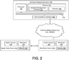
- the system includes a server 100, a hub radio device 102 and a spoke radio device 104.
- the hub and spoke radio devices 102, 104 may be TVBDs.
- each of the server 100, the hub radio device 102 and the spoke radio device 104 are configured to carry out the respective logical functions that are described herein.
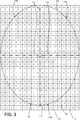
- the coverage area 106 has a maximum range of about 10 miles (about 16 kilometers) from the location of the hub radio device 102.
- the geographic area that includes the coverage area 106 is divided into square-shaped pixels 108.
- a representative maximum allowable transmit power in dBm for the pixel 108 is shown for a channel that is available to serve as a generic access channel for a spoke radio device 104 ( FIG. 2 ) located in the coverage area 106.
- the pixels 108 may be shapes other than squares, such as rectangles or hexagons.
- the coverage area 106 of the hub radio device 102 is divided into areas, or sub-regions 110.
- the coverage area 106 is divided into four sub-regions, respectively labeled 110a, 110b, 110c and 110d.
- a maximum transmit power limit for generic radio operations is determined for each sub-regions 110.
- a spoke radio device 104 that seeks to communicate under a generic channel authorization determines the sub-region 110 of the coverage area 106 in which it is physically present and uses the corresponding maximum transmit power level for communications with the hub radio device 102.
- the sub-regions 110 are non-overlapping but are contiguous with one another so that, when combined, have substantially the same shape and size as the coverage area 106.
- the sub-regions 110 are sectors of the coverage area 106.
- each sub-region 110 is defined by two radii 112 (shown using dash-dot lines) that extend from the location of the hub radio device 102.
- the sectors may or may not be further defined by a third leg that coincides with the contour of the coverage area 106.
- the third leg may be an arc of the circle or the ellipse. In other cases, the third leg will follow the regular or irregular contour of the coverage area 106 between points where the radii 112 intersect the contour.
- Each sub-region 110 defines a shape and may be expressed or defined in an appropriate manner, such as using an Environmental Systems Research Institute, Inc. (ESRI) shapefile (e.g., .shp file format), using azimuths and/or vectors relative to the location of the hub radio device 102, pixels, GIS coordinates, etc.
- ESRI Environmental Systems Research Institute, Inc.
- the coverage area 106 of the hub radio device 102 is divided into four sub-regions 110, each of which is an equally sized sector (by azimuth). It will be understood that there may be more than or less than four sub-regions 110. Also, the sub-regions 110 need not be sectors and need not have equal sizes.
- a maximum transmit power level for use in generic access communications for a channel may be identified for each sub-region 110.
- the maximum transmit power level for a sub-region 110 for a given channel is the lowest allowable transmit power value found in any of the pixels that overlap with the sub-regions 110.
- the maximum transmit power level for use in generic access communications for an exemplary channel is +12 dBm for the sub-region 110b (the upper right quadrant of the coverage area 106 between 0° and 90°).
- the maximum transmit power level for use in generic access communications is 0 dBm for the sub-region 110d (the lower right quadrant between 90° and 180°).
- the maximum transmit power level for use in generic access communications is +8 dBm for the sub-region 110c (the lower left quadrant between 180° and 270°).
- the maximum transmit power level for use in generic access communications for the sub-region 110a is +30 dBm (the upper left quadrant between 270° and 360°).
- the maximum transmit power level for each sub-region 110 is the generic transmit power limit found in the sub-region 110.
- the variation in results among the sub-regions 110 provides a distinct advantage over using the lowest generic transmit power level for the entire coverage area 106 of the hub radio device 102. This is because a spoke radio device 104 in any sub-region 110 other than the sub-region 110 with the lowest generic transmit power for the entire coverage area 106 may transmit with more power than is allowed in the conventional approach.
- a format may be established to communicate the generic operating parameters for each sub-region 110.
- the generic operating parameters for each sub-region 110 may be broadcast in a beacon transmitted by the hub radio device 102.
- the beacon also may include information that geographically defines each sub-region 110.
- the information includes location of the hub radio device 102 (e.g., specified by latitude and longitude) and, for each channel, an identification of each sub-region 110 and, for each channel/sub-region combination, a transmit power value.
- each sub-region 110 may be identified by a pair of azimuths (e.g., an azimuth start and an azimuth stop).
- the information may be provided in list or table form, such as set forth in representative table 2.
- Table 2 is populated with exemplary data, but excludes latitude and longitude values for the location of the hub radio device 102 since this data may be identified separately. Also identified separately may be information that geographically identifies each sub-region 110.
- Data to geographically identify each sub-region 110 for this example is set forth in table 3. It will be appreciated that the information from tables 2 and 3 may be merged. In the examples, thirteen channels are identified. It will be appreciated that there may be more than 13 channels or less than 13 channels. Also, in one aspect of the invention, the data may exclude channels that the hub radio device 102 is not authorized to use (e.g., channels not specified as available in the hub's specific white space channel list).
- the permissible spoke operating parameters may be determined by the central server 100.
- the spoke radio device 104 may determine a channel and transmit power to use to initiate a communication link with the hub radio device 102. As part of this determination, the spoke radio device 104 may be responsible for identifying the sub-region 110 in which the spoke radio device 104 is located.
- the spoke radio device 103 is a location-aware cognitive radio and may determine its location using a location acquisition means (e.g., a GPS receiver) or from stored information (e.g., in the case of a fixed-location device, a location programmed by an installer). This location may be compared to the location of the hub radio device 102 to calculate an azimuth angle from the hub radio device 102 to the spoke radio device 104.
- a location acquisition means e.g., a GPS receiver
- stored information e.g., in the case of a fixed-location device, a location programmed by an installer
- This azimuth value is compared against the azimuth start and stop angles that are used to geographically identify the sub-regions 110 so as to identify the sub-region 110 in which the spoke radio device 104 is located. If the sub-regions 104 are specified in other ways (e.g., GIS data, a collection of coordinates, etc.), other appropriate approaches may be used by the spoke radio device 104 to determine the sub-region 110 in which the spoke radio device 104 is located.
- the spoke radio device 104 may select a channel from the channels identified in the beacon.
- the selected channel may be the channel with the highest allowable transmit power for the sub-region 110 in which the spoke is located.
- channel selection may be based on other information, such as a preferred channel indication from the hub radio device 102.
- the source radio device 104 may attempt to establish a communication link with the hub radio device 102 for purposes of acquiring specific channel authorization from the server 100.
- the disclosed techniques result in finer resolution generic operating parameters than the conventional approach by using logically partitioned "sub" areas of the coverage area 106 of the hub radio device 102.
- the number of sub-regions 110 may be selected (e.g., optimized) to balance the amount of data that is included in beacons broadcast by the hub radio device 102 versus attempting to increase the potential for the spoke radio device 104 to be located in a sub-region 110 with a relatively high transmit power limit for one or more channels.
- the hub radio device 102 communicates with the server 100 to acquire the generic operating parameters for inclusion in the beacon.
- the server 100 may determine the sub-regions 110 or the hub radio device 102 may determine the sub-regions 110. In either case, the server 100 assesses known data regarding protected transmitters to determine the generic transmit power value for each sub-region 110 and for each channel on which the hub radio device 02 may engage in generic radio access communications with spoke radio devices 104.
- the server 100 may make modifications to the generic transmit power values if there is a change in the spectrum environment, such as when a new protected transmitter becomes present.
- each device includes appropriate control circuitry and/or processors and memory components.
- Logical instructions to carry out the respective processes may be embodied as software that is executed by the relevant device and that is stored on a non-transitory computer readable medium (e.g., computer memory) of the relevant device.
- FIG. 2 is a schematic block diagram of an exemplary system for implementing the disclosed techniques.
- the hub radio device 102 may be or may include any type of electronic device that engages in wireless communications, such a computing device, an information and/or entertainment system, a modem and router for providing Internet connectivity to other devices, etc.
- the hub radio device 102 is a fixed-location device, but could be a mobile device, such as a mobile phone, tablet, etc.
- the spoke radio device 104 may be or may include any type of fixed or mobile electronic device that engages in wireless communications, such a computing device, an information and/or entertainment system, a mobile phone, a modem and router for providing Internet connectivity to other devices, etc.
- the server 100 communicates with the hub radio device 102 over any appropriate communications medium 114, such as one or more of the Internet, a cellular network, a WiFi network, etc.
- the server 100 may be a central white space registration system or some other form of spectrum management platform.
- the spoke radio device 104 is location aware. For instance, the spoke radio device 104 may be capable of determining its position (also referred to as geo-location) using a location-determining technique, such as GPS or other technology. In some aspects of the invention, the spoke radio device 104 may have a GPS receiver that is used to receive GPS satellite signals from which position coordinates are triangulated. Furthermore, if the spoke radio device 104 is a mobile device, it may be capable of manually or autonomously updating its determined position as it moves.
- the spoke radio device 104 includes communications circuitry, such as radio circuitry 116.
- the radio circuitry 116 may include one or more radio modems (e.g., radio transceivers) and corresponding antenna assemblies to allow for communications over various types of network connections and/or protocols.
- the radio circuitry 116 may be used to carry out various wireless communications functions, including communicating with the hub radio device 102 using generic access credentials.
- the spoke radio device 104 may use the hub radio device 102 as a proxy to gain specific access credentials or may communicate with the server 100 via the hub radio device 102 to gain specific access credentials.
- the spoke radio device 104 may engage in various communications functions such as, but not limited to, engaging in voice or video calls, and sending or receiving messages (e.g., email messages, text messages, multimedia messages, instant messages, etc.), accessing the Internet, transferring data (e.g., streaming video, obtaining or sending files), etc.
- messages e.g., email messages, text messages, multimedia messages, instant messages, etc.
- accessing the Internet e.g., streaming video, obtaining or sending files, etc.
- the spoke radio device 104 may be controlled by a control circuit that includes a processing device 118.
- the processing device 118 may execute code that is stored in a memory 120.
- the processing device 118 may be used to execute an operating system and other applications that are installed on the spoke radio device 104.
- the operating system or applications may include executable logic to implement the functions of the spoke radio device 104 that are described herein.
- the memory 120 is a non-transitory computer readable medium and may be, for example, one or more of a buffer, a flash memory, a hard drive, a removable media, a volatile memory, a non-volatile memory, a random access memory (RAM), or other suitable device.
- the memory 120 includes a non-volatile memory for long term data storage and a volatile memory that functions as system memory for the control circuit.
- the spoke radio device 104 may include any other appropriate components such as, but not limited to, a display, a speaker, a microphone, a user interface (e.g., a keypad and/or a touch-sensitive input), motion sensors, etc.
- the hub radio device 102 includes communications circuitry, such as radio circuitry 122.
- the radio circuitry 122 may include one or more radio modems (e.g., radio transceivers) and corresponding antenna assemblies to allow for communications over various types of network connections and/or protocols.
- the radio circuitry 122 may be used to carry out various wireless communications functions, including communicating with the spoke radio device 104 using generic access credentials.
- the processing device 124 may execute code that is stored in a memory 126.
- the processing device 124 may be used to execute an operating system and other applications that are installed on the hub radio device 102.
- the operating system or applications may include executable logic to implement the functions of the hub radio device 102 that are described herein.
- the memory 126 is a non-transitory computer readable medium and may be, for example, one or more of a buffer, a flash memory, a hard drive, a removable media, a volatile memory, a non-volatile memory, a random access memory (RAM), or other suitable device.
- the memory 126 includes a non-volatile memory for long term data storage and a volatile memory that functions as system memory for the control circuit.
- the hub radio device 102 may include any other appropriate components such as, but not limited to, a display, a speaker, a microphone, a user interface (e.g., a keypad and/or a touch-sensitive input), motion sensors, etc.
- the server 100 may be implemented as a computer-based system that is capable of executing computer applications (e.g., software programs), including a spectrum management function 128 that, when executed, carries out functions of the server 100 that are described herein.
- the spectrum management function 128 and a database 130 may be stored on a non-transitory computer readable medium, such as a memory 132.
- the database 130 may be used to store various information sets used to carry out the functions described in this disclosure.
- the server 100 may store or access data about known protected radio devices.
- the memory 132 may be a magnetic, optical or electronic storage device (e.g., hard disk, optical disk, flash memory, etc.), and may comprise several devices, including volatile and non-volatile memory components.
- the memory 132 may include, for example, random access memory (RAM) for acting as system memory, read-only memory (ROM), solid-state drives, hard disks, optical disks (e.g., CDs and DVDs), tapes, flash devices and/or other memory components, plus associated drives, players and/or readers for the memory devices.
- RAM random access memory
- ROM read-only memory
- solid-state drives hard disks
- optical disks e.g., CDs and DVDs
- tapes e.g., CDs and DVDs
- the server 100 may include one or more processors 134 used to execute instructions that carry out logic routines.
- the processor 134 and the memory 132 may be coupled using a local interface 136.
- the local interface 136 may be, for example, a data bus with accompanying control bus, a network, or other subsystem.
- the server 100 may have various input/output (I/O) interfaces for operatively connecting to various peripheral devices, as well as one or more communications interfaces 138.
- the communications interface 138 may include for example, a modem and/or a network interface card.
- the communications interface 138 may enable the server 10 to send and receive data signals, voice signals, video signals, and the like to and from other computing devices via an external network.
- the communications interface 138 may operatively connect the server 100 to the communications medium 114.
- the server 100 may be configured to host the above-described services for a plurality of electronic devices, including the hub and spoke radio devices 102, 104.
- the services may include spectrum management functions, such as providing channel lists, specific channel access credentials and/or generic channel access credentials to qualified radio devices upon registration so as to allow the radio devices to make use of spectrum for wireless communications.
- the server 100 may host an Internet-style website for the various corresponding parties to conduct initial enrollment with the server 100, conduct manual registration if needed, access various tools and reports supplied by the server 100, and so forth.
- the server 100 may collect spectrum usage information from various sources, including but not limited to public databases, private databases and deployed radio devices (e.g., in the form of channel use selections or spectrum sensing results).
- the database information may contain information about known spectrum users, such as incumbent spectrum users (e.g., digital television stations, wireless microphone systems, cable head end systems, FM radio stations, etc.), licensed spectrum users, or radio systems that are exempt from seeking channel map information in order to operate.
- incumbent spectrum users e.g., digital television stations, wireless microphone systems, cable head end systems, FM radio stations, etc.
- licensed spectrum users e.g., licensed spectrum users, or radio systems that are exempt from seeking channel map information in order to operate.
- the server may undertake spectrum management functions other than those that are described in detail, such as responding to white space channel list requests with appropriate channel lists. Therefore, in some aspects of the invention, the server may be considered a central spectrum "database” or white space registration/allocation system.
- aspects of the disclosed systems and methods are independent of the type or types of devices that may use spectrum.
- the systems and methods may be applied in any operational context for wireless communications, and wireless communications are expressly intended to encompass unidirectional signal transmissions (e.g., broadcasting of a signal for receipt by a device without response) and to encompass bidirectional communications where devices engage in the exchange of signals.
- the methods and systems may be applied to dumb and/or cognitive radio devices.
- the methods and systems may be applied to licensed or unlicensed spectrum, including but not limited to shared spectrum environments such as white spaces (e.g., TV white spaces or TVWS) where available channels are interleaved with licensed channels.
- the methods and systems are generic to modulation schemes, harmonic considerations, frequency bands or channels used by the electronic device, the type of data or information that is transmitted, how the electronic device uses received information, and other similar communications considerations.
- the systems and methods have application in any suitable environment.
Landscapes
- Engineering & Computer Science (AREA)
- Signal Processing (AREA)
- Computer Networks & Wireless Communication (AREA)
- Business, Economics & Management (AREA)
- General Business, Economics & Management (AREA)
- Mobile Radio Communication Systems (AREA)
Description
- The technology of the present disclosure relates generally to wireless communications and, more particularly, to devices facilitating channel map acquisition in "spoke" radio devices that do not have a direct Internet connection. The channel map may be acquired through a "hub" radio device that does have an Internet connection. Interference to protected radio devices caused by link establishment between the spoke and hub radio devices is minimized.
-
US 2010/330919 relates to a method of determining operating parameters for a secondary system transmitter.WO 2013/093551 relates to link specific parameters based on emission characteristics of a device.WO 2013/038234 relates to maximum transmission power for white space devices based on the maximum degradation.US 2013/300941 relates to enablement in TV white spaces.WO 2012/138800 relates to communication in a white space. Spectrum sharing is thought of as one of the most viable ways of improving the amount of spectrum available to wireless networks and other radio devices for conducting wireless communications. An exemplary spectrum sharing technique involves use of television white spaces under regulations set forth by an appropriate regulatory agency. An exemplary regulatory agency that regulates the use of wireless spectrum is the U.S. Federal Communications Commission (FCC). Other countries may have similar regulatory entities. - In the U.S., for example, the FCC has eliminated analog television (TV) broadcasts in favor of digital TV broadcasts. This has freed spectrum channels for use by unlicensed radio systems to offer various services, such as mobile communications and Internet access. In this context, the freed spectrum is commonly referred to as TV white space (or TVWS) but other types of white spaces are possible. In the case of TV white space, the white space is comprised of unused spectrum that is interleaved with spectrum used by incumbent radio devices in the
channel 2 to channel 51 range (corresponding to 54 MHz to 698 MHz). Exemplary incumbent radio devices for TV white space include television broadcasters and other priority users of television channels. Under FCC regulations, for example, radio devices that use TVWS must register with a central database server (also referred to as a spectrum management server) and receive a channel list (also referred to as a channel map) of available channels for which the radio device may use in a shared environment with other TV band devices (TVBDs) while minimizing the possibility of creating undesirable interference to incumbent radio systems. The channel list that is generated for a radio device is generated by the central database server based on the location of the radio device. In this manner, the operation of incumbent radio devices having protected areas in which the radio device is located may be taken into account when determining channel availability. - Also, regulators and industry groups have proposed the use of geo-location database technology to control or manage spectrum access for radios in other situations. For example, use of geo-location database technology has been proposed for the 5 GHz UNII bands and for the 3.550 GHz to 3.650 GHz bands in which the U.S. government and military are incumbent users.
- Outside the U.S., use of geo-location database technology has been proposed for TVWS bands in a number of countries. In the European Union (EU), TVWS sharing is often referred to as authorized shared access (ASA) and/or licensed shared access (LSA). Exemplary regulations for ASA/LSA are outlined in European Telecommunications Standards Institute (ETSI) EN 301 598. Other standards bodies have also proposed mechanisms for supporting spectrum sharing, such as the Internet Engineering Task Force's (IETF) Protocol to Access White Space (PAWS).
- In cognitive radio ecosystems, such as the above-mentioned TV white space environment, it is common for a first radio device (e.g., a first TVBD) to establish wireless connectivity with a second radio device (e.g., a second TVBD). Under controlling regulations, the connectivity typically must be established without causing interference to primary, incumbent or other concurrent radio devices (collectively referred to as incumbent users).
- An exemplary radio device involved in this situation may be a fixed-location TVDB device that is connected to the Internet over a medium that does not cause impermissible interference to another radio device. The medium over which Internet connectivity is made may be, for example, a terrestrial connection or a cellular connection. As will become clear from the following, this radio device may be considered a hub radio device due to its relationship with another radio device, which may be considered a spoke radio device.
- The hub radio device may acquire a channel list from a geo-location database (also referred to a spectrum management server). The channel list authorizes the hub radio device to transmit on specified channels, at a specified location, at a maximum power, and for a specified period of time.
- An issue arises when the spoke radio device (another TVBD in the example), which does not have independent access to the Internet, attempts to acquire a channel list from the geo-location database using a radio link established with the hub radio device as a pathway for Internet access. The two radio devices are considered hub and spoke radio devices due to their relationship with one another relative to the Internet connection.
- Since the spoke radio device is in a different location than the hub radio device, an authorized channel list for the spoke radio device may not include an authorization for the same channel(s) used by the hub radio device. The channels used by the hub radio device may not be authorized for use by TVBDs, including the spoke radio device, in the location of the spoke radio device due to presence of an incumbent user with a protected boundary area that encompasses the location of the spoke radio device, but not the location of the hub radio device.
- This is a dilemma. But, at least in the U.S., the Federal Communications Commission (FCC) considers this a special situation and allows limited use of the operational channel of the hub radio device by the spoke radio device under the following regulation set forth in 47 C.F.R. § 15.711(e):
Fixed devices without a direct connection to the Internet. If a fixed TVBD does not have a direct connection to the Internet and has not yet been initialized and registered with the TV bands database consistent with §15.713, but can receive the transmissions of another fixed TVBD, the fixed TVBD needing initialization may transmit to that other fixed TVBD on either a channel that the other TVBD has transmitted on or on a channel which the other TVBD indicates is available for use to access the database to register its location and receive a list of channels that are available for it to use. Subsequently, the newly registered TVBD must only use the television channels that the database indicates are available for it to use. A fixed device may not obtain lists of available channels from another fixed device as provided by a TV bands database for such other device, i.e., a fixed device may not simply operate on the list of available channels provided by a TV bands database for another fixed device with which it communicates but must contact a database to obtain a list of available channels on which it may operate. - A consequence of this pragmatic methodology is the creation of a transient condition that might cause brief unintended interference to operations of incumbent users.
- Other approaches may result in comparatively less transient interference in this situation. For example, certain regulations do not allow the flexibility of temporary communications that exceed certain transmit power thresholds. Unfortunately, these constraints have consequences that may promote unreliable or artificially hindered communications. As an example, European regulators have specified a situation in which a fixed device (e.g., the hub in the foregoing example) with a terrestrial connection to a database/server may acquire a "generic" channel authorization list and a "specific" channel authentication list. The specific channel authorization list allows normal use of the channel(s) in the list with other devices that also have specific authorization to use the channel(s). The "generic" channel authorization list allows communications with devices that do not have specific authorization, but these communications are more constrained.
- The generic list of channels is the same as the specific list of channels, but includes a transmit power limit for each channel. The transmit power limit is the lowest authorized transmit power at any location in the hub's coverage area. The spoke, regardless of its location in the coverage area of the hub, may not transmit with a power above the limit for the relevant channel. The transmit power limit values may differ on a channel-by-channel basis.
- More specifically, the area that includes the coverage area of the hub radio device is broken up into "pixels" where each pixel is a square unit area or some other predefined shape and area. The transmit power limit for each channel is determined by comparing the maximum allowable transmit power for every "pixel" overlapping with the coverage area and selecting the lowest value for the channel. This "lowest value" represents the maximum allowable transmit power for the channel that may be used by another non-specifically authorized device during communications with the hub (e.g., to use the hub as a pathway or proxy to obtain a channel list). To make other radio devices aware of the generic channel availability, the hub radio device broadcasts a beacon with a list of channels and an allowable transmit power for each channel in the list.
- An exemplary channel list with generic operating parameters for the entirety of the hub's coverage area may be specified in a simple list format or in a table format with channel and transmit power entries (CH, TX POWER). An example is set forth in table 1.
Table 1 Channel Transmit Power CH 1 0 dBm CH 2 12 dBm ⋮ ⋮ CH 13 3 dBm - Under this approach, the spoke radio device may use the generic operational parameters specified in the beacon to communicate with the hub, including the generic transmit power as a maximum transmit power. By way of these communications and using the hub radio device as a communications pathway or proxy, the spoke radio device may request specific operational parameters (e.g., an authorized channel list) for the geographic location of the spoke radio device from the server hosting the geo-location database functions.
- But, as shown in
FIG. 1 , it is likely that the specific operational parameters will be more favorable (i.e., allow higher transmit power) and enable a more reliable communications link than the generic parameters.FIG. 1 shows an exemplaryhub radio device 10 and acoverage area 12 of thehub radio device 10. In the illustrated example, thecoverage area 12 has a maximum range of about 10 miles (about 16 kilometers) from the location of thehub radio device 10. The geographic area that includes thecoverage area 12 is divided into square-shaped pixels. In each pixel, a representative maximum allowable transmit power in dBm for the pixel is shown for a single channel. Also shown are two exemplaryspoke radio devices coverage area 12 of thehub radio device 10. In the illustrated example, thehub radio device 10 may be authorized to transmit at 30 dBm at its specific location. If it had specific channel authorization to use the channel of the illustrated example, thespoke radio device 14a also would be able to transmit at 30 dBm. But the lowest allowable transmit power in theexemplary coverage area 12, which occurs at the location of thespoke radio device 14b, is only 0 dBm. This lowest allowable transmit power represents the generic transmit power limit for the channel for theentire coverage area 12. Therefore, without specific authorization, thespoke radio device 14a in this example may communicate with thehub radio device 10 using a maximum transmit power of 0 dBm. - In this scenario, is that it is highly unlikely that the
hub radio device 10 will receive transmitted data from thespoke radio devices spoke radio devices hub radio device 10. Signal reception will still be a problem even if the data rate is drastically reduced to increase link budget. Moreover, reducing the data rate further complicates the situation by requiring thehub radio device 10 to listen at varying data rates. - Another problem occurs if the
hub radio device 10 and thespoke radio device hub radio device 10 may reacquire specific operating parameters due to a reboot or expiration of earlier specific operating parameters. In this case, further communications over the original link between thehub radio device 10 and thespoke radio device 14 may not be possible, thereby artificially inhibiting communications. -
-
FIG. 1 is a schematic view of a representative spectrum environment in which generic channel authorizations are determined in a conventional manner. -
FIG. 2 is a schematic diagram of an exemplary system for facilitating channel map acquisition for spoke radio devices according to the present invention. -
FIG. 3 is a schematic view of a representative spectrum environment in which generic channel authorizations are determined by the system ofFIG. 2 . - Aspects and preferred features are set out in the accompanying claims. Aspects of the invention will now be described with reference to the drawings, wherein like reference numerals are used to refer to like elements throughout. It will be understood that the figures are not necessarily to scale. Features that are described and/or illustrated with respect to one aspect of the invention may be used in the same way or in a similar way in one or more other aspects of the invention and/or in combination with or instead of the features of the other aspects of the invention. The invention is defined in the independent claims. Additional features of the invention are provided in the dependent claims. The embodiments and/or examples disclosed in the following description which are not covered by the appended claims are considered as not being part of the present invention.
- Disclosed are systems and methods to determine generic operating parameters for areas that are smaller than an entire coverage area of a hub radio device. The generic operating parameters may be established by a central geo-location database server and supplied to the hub radio device for broadcast in a beacon transmitted by the hub radio device. The generic operating parameters are established in a manner that minimizes the possibility of creating undesirable interference to protected radio systems. The central geo-location database server may be a whitespace management server that supplies white space channel maps (also referred to as a white space channel lists) or other white space spectrum authorizations to TVBDs.
- With reference to
FIG. 2 , shown is an exemplary system in which channel map acquisition for spoke radio devices that do not have a direct Internet connection is facilitated. The system includes aserver 100, ahub radio device 102 and aspoke radio device 104. The hub and spokeradio devices server 100, thehub radio device 102 and thespoke radio device 104 are configured to carry out the respective logical functions that are described herein. - With additional reference to
FIG. 3 , shown is an exemplaryhub radio device 102 surrounded by a correspondingcoverage area 106 of thehub radio device 102. In the illustrated example, thecoverage area 106 has a maximum range of about 10 miles (about 16 kilometers) from the location of thehub radio device 102. The geographic area that includes thecoverage area 106 is divided into square-shapedpixels 108. In eachpixel 108, a representative maximum allowable transmit power in dBm for thepixel 108 is shown for a channel that is available to serve as a generic access channel for a spoke radio device 104 (FIG. 2 ) located in thecoverage area 106. Thepixels 108 may be shapes other than squares, such as rectangles or hexagons. - In one aspect of the invention, the
coverage area 106 of thehub radio device 102 is divided into areas, or sub-regions 110. In the illustrated example, thecoverage area 106 is divided into four sub-regions, respectively labeled 110a, 110b, 110c and 110d. A maximum transmit power limit for generic radio operations is determined for each sub-regions 110. A spokeradio device 104 that seeks to communicate under a generic channel authorization determines the sub-region 110 of thecoverage area 106 in which it is physically present and uses the corresponding maximum transmit power level for communications with thehub radio device 102. In one aspect of the invention, the sub-regions 110 are non-overlapping but are contiguous with one another so that, when combined, have substantially the same shape and size as thecoverage area 106. In a more specific aspect of the invention, the sub-regions 110 are sectors of thecoverage area 106. In this case, each sub-region 110 is defined by two radii 112 (shown using dash-dot lines) that extend from the location of thehub radio device 102. The sectors may or may not be further defined by a third leg that coincides with the contour of thecoverage area 106. In the case where a third leg is used and thecoverage area 106 is a circle or an ellipse, the third leg may be an arc of the circle or the ellipse. In other cases, the third leg will follow the regular or irregular contour of thecoverage area 106 between points where theradii 112 intersect the contour. Each sub-region 110 defines a shape and may be expressed or defined in an appropriate manner, such as using an Environmental Systems Research Institute, Inc. (ESRI) shapefile (e.g., .shp file format), using azimuths and/or vectors relative to the location of thehub radio device 102, pixels, GIS coordinates, etc. - In the illustrated example of
FIG. 3 , thecoverage area 106 of thehub radio device 102 is divided into four sub-regions 110, each of which is an equally sized sector (by azimuth). It will be understood that there may be more than or less than four sub-regions 110. Also, the sub-regions 110 need not be sectors and need not have equal sizes. - A maximum transmit power level for use in generic access communications for a channel may be identified for each sub-region 110. The maximum transmit power level for a sub-region 110 for a given channel is the lowest allowable transmit power value found in any of the pixels that overlap with the sub-regions 110. In the illustrated example of
FIG. 3 , the maximum transmit power level for use in generic access communications for an exemplary channel is +12 dBm for thesub-region 110b (the upper right quadrant of thecoverage area 106 between 0° and 90°). For the same channel, the maximum transmit power level for use in generic access communications is 0 dBm for thesub-region 110d (the lower right quadrant between 90° and 180°). For the same channel, the maximum transmit power level for use in generic access communications is +8 dBm for thesub-region 110c (the lower left quadrant between 180° and 270°). Similarly, for the same channel, the maximum transmit power level for use in generic access communications for thesub-region 110a is +30 dBm (the upper left quadrant between 270° and 360°). - The maximum transmit power level for each sub-region 110 is the generic transmit power limit found in the sub-region 110. The variation in results among the sub-regions 110 provides a distinct advantage over using the lowest generic transmit power level for the
entire coverage area 106 of thehub radio device 102. This is because aspoke radio device 104 in any sub-region 110 other than the sub-region 110 with the lowest generic transmit power for theentire coverage area 106 may transmit with more power than is allowed in the conventional approach. - A format may be established to communicate the generic operating parameters for each sub-region 110. The generic operating parameters for each sub-region 110 may be broadcast in a beacon transmitted by the
hub radio device 102. The beacon also may include information that geographically defines each sub-region 110. - In one exemplary aspect of the invention, the information includes location of the hub radio device 102 (e.g., specified by latitude and longitude) and, for each channel, an identification of each sub-region 110 and, for each channel/sub-region combination, a transmit power value. When the sub-regions 110 are sectors, each sub-region 110 may be identified by a pair of azimuths (e.g., an azimuth start and an azimuth stop). Thus, the information may be provided in list or table form, such as set forth in representative table 2. Table 2 is populated with exemplary data, but excludes latitude and longitude values for the location of the
hub radio device 102 since this data may be identified separately. Also identified separately may be information that geographically identifies each sub-region 110. Data to geographically identify each sub-region 110 for this example is set forth in table 3. It will be appreciated that the information from tables 2 and 3 may be merged. In the examples, thirteen channels are identified. It will be appreciated that there may be more than 13 channels or less than 13 channels. Also, in one aspect of the invention, the data may exclude channels that thehub radio device 102 is not authorized to use (e.g., channels not specified as available in the hub's specific white space channel list).Table 2 Channel Area 1 Area 2Area 3 Area 4CH1 12 dBm 0 dBm 8 dBm 30 dBm CH2 12 dBm 12 dBm 15 dBm 18 dBm ⋮ ⋮ ⋮ ⋮ ⋮ CH13 30 dBm 17 dBm 3 dBm 11 dBm Table 3 Area 1Area 2Area 3 Area 4Azimuth Start Azimuth Stop Azimuth Start Azimuth Stop Azimuth Start Azimuth Stop Azimuth Start Azimuth Stop 0° 90° 90° 180° 180° 270° 270° 360° - As indicated, the permissible spoke operating parameters, including the sub-region definitions, may be determined by the
central server 100. - After receiving the beacon from the
hub radio device 102, thespoke radio device 104 may determine a channel and transmit power to use to initiate a communication link with thehub radio device 102. As part of this determination, thespoke radio device 104 may be responsible for identifying the sub-region 110 in which thespoke radio device 104 is located. In one aspect of the invention, the spoke radio device 103 is a location-aware cognitive radio and may determine its location using a location acquisition means (e.g., a GPS receiver) or from stored information (e.g., in the case of a fixed-location device, a location programmed by an installer). This location may be compared to the location of thehub radio device 102 to calculate an azimuth angle from thehub radio device 102 to thespoke radio device 104. This azimuth value is compared against the azimuth start and stop angles that are used to geographically identify the sub-regions 110 so as to identify the sub-region 110 in which thespoke radio device 104 is located. If thesub-regions 104 are specified in other ways (e.g., GIS data, a collection of coordinates, etc.), other appropriate approaches may be used by thespoke radio device 104 to determine the sub-region 110 in which thespoke radio device 104 is located. - Once the sub-region 140 in which the
spoke radio device 104 is located is determined, thespoke radio device 104 may select a channel from the channels identified in the beacon. The selected channel may be the channel with the highest allowable transmit power for the sub-region 110 in which the spoke is located. In another aspect of the invention, channel selection may be based on other information, such as a preferred channel indication from thehub radio device 102. Once the channel is selected, thesource radio device 104 may attempt to establish a communication link with thehub radio device 102 for purposes of acquiring specific channel authorization from theserver 100. - The disclosed techniques result in finer resolution generic operating parameters than the conventional approach by using logically partitioned "sub" areas of the
coverage area 106 of thehub radio device 102. The number of sub-regions 110 may be selected (e.g., optimized) to balance the amount of data that is included in beacons broadcast by thehub radio device 102 versus attempting to increase the potential for thespoke radio device 104 to be located in a sub-region 110 with a relatively high transmit power limit for one or more channels. - In one aspect of the invention, the
hub radio device 102 communicates with theserver 100 to acquire the generic operating parameters for inclusion in the beacon. Theserver 100 may determine the sub-regions 110 or thehub radio device 102 may determine the sub-regions 110. In either case, theserver 100 assesses known data regarding protected transmitters to determine the generic transmit power value for each sub-region 110 and for each channel on which the hub radio device 02 may engage in generic radio access communications withspoke radio devices 104. Theserver 100 may make modifications to the generic transmit power values if there is a change in the spectrum environment, such as when a new protected transmitter becomes present. - It will be understood that some of the described operations are carried out by the
server 100, some of the operations are carried out by thehub radio device 102, and some of the operations are carried out by thespoke radio device 104. Tasks carried out by each device respectively may be considered a method carried out by that device. For these purposes, each of these devices includes appropriate control circuitry and/or processors and memory components. Logical instructions to carry out the respective processes may be embodied as software that is executed by the relevant device and that is stored on a non-transitory computer readable medium (e.g., computer memory) of the relevant device. - The
server 100 communicates with thehub radio device 102 over any appropriate communications medium 114, such as one or more of the Internet, a cellular network, a WiFi network, etc. In addition to carrying out the operations described herein, theserver 100 may be a central white space registration system or some other form of spectrum management platform. - The
spoke radio device 104 is location aware. For instance, thespoke radio device 104 may be capable of determining its position (also referred to as geo-location) using a location-determining technique, such as GPS or other technology. In some aspects of the invention, thespoke radio device 104 may have a GPS receiver that is used to receive GPS satellite signals from which position coordinates are triangulated. Furthermore, if thespoke radio device 104 is a mobile device, it may be capable of manually or autonomously updating its determined position as it moves. - The
spoke radio device 104 includes communications circuitry, such asradio circuitry 116. Theradio circuitry 116 may include one or more radio modems (e.g., radio transceivers) and corresponding antenna assemblies to allow for communications over various types of network connections and/or protocols. Theradio circuitry 116 may be used to carry out various wireless communications functions, including communicating with thehub radio device 102 using generic access credentials. Thespoke radio device 104 may use thehub radio device 102 as a proxy to gain specific access credentials or may communicate with theserver 100 via thehub radio device 102 to gain specific access credentials. Once specific access credentials are acquired by thespoke radio device 104, thespoke radio device 104 may engage in various communications functions such as, but not limited to, engaging in voice or video calls, and sending or receiving messages (e.g., email messages, text messages, multimedia messages, instant messages, etc.), accessing the Internet, transferring data (e.g., streaming video, obtaining or sending files), etc. - Overall functionality of the
spoke radio device 104 may be controlled by a control circuit that includes aprocessing device 118. Theprocessing device 118 may execute code that is stored in amemory 120. For instance, theprocessing device 118 may be used to execute an operating system and other applications that are installed on thespoke radio device 104. The operating system or applications may include executable logic to implement the functions of thespoke radio device 104 that are described herein. Thememory 120 is a non-transitory computer readable medium and may be, for example, one or more of a buffer, a flash memory, a hard drive, a removable media, a volatile memory, a non-volatile memory, a random access memory (RAM), or other suitable device. In a typical arrangement, thememory 120 includes a non-volatile memory for long term data storage and a volatile memory that functions as system memory for the control circuit. - The
spoke radio device 104 may include any other appropriate components such as, but not limited to, a display, a speaker, a microphone, a user interface (e.g., a keypad and/or a touch-sensitive input), motion sensors, etc. - Similar to the
spoke radio device 104, thehub radio device 102 includes communications circuitry, such asradio circuitry 122. Theradio circuitry 122 may include one or more radio modems (e.g., radio transceivers) and corresponding antenna assemblies to allow for communications over various types of network connections and/or protocols. Theradio circuitry 122 may be used to carry out various wireless communications functions, including communicating with thespoke radio device 104 using generic access credentials. - Overall functionality of the
hub radio device 102 may be controlled by a control circuit that includes aprocessing device 124. Theprocessing device 124 may execute code that is stored in amemory 126. For instance, theprocessing device 124 may be used to execute an operating system and other applications that are installed on thehub radio device 102. The operating system or applications may include executable logic to implement the functions of thehub radio device 102 that are described herein. Thememory 126 is a non-transitory computer readable medium and may be, for example, one or more of a buffer, a flash memory, a hard drive, a removable media, a volatile memory, a non-volatile memory, a random access memory (RAM), or other suitable device. In a typical arrangement, thememory 126 includes a non-volatile memory for long term data storage and a volatile memory that functions as system memory for the control circuit. - The
hub radio device 102 may include any other appropriate components such as, but not limited to, a display, a speaker, a microphone, a user interface (e.g., a keypad and/or a touch-sensitive input), motion sensors, etc. - The
server 100 may be implemented as a computer-based system that is capable of executing computer applications (e.g., software programs), including aspectrum management function 128 that, when executed, carries out functions of theserver 100 that are described herein. Thespectrum management function 128 and adatabase 130 may be stored on a non-transitory computer readable medium, such as amemory 132. Thedatabase 130 may be used to store various information sets used to carry out the functions described in this disclosure. For instance, theserver 100 may store or access data about known protected radio devices. Thememory 132 may be a magnetic, optical or electronic storage device (e.g., hard disk, optical disk, flash memory, etc.), and may comprise several devices, including volatile and non-volatile memory components. Accordingly, thememory 132 may include, for example, random access memory (RAM) for acting as system memory, read-only memory (ROM), solid-state drives, hard disks, optical disks (e.g., CDs and DVDs), tapes, flash devices and/or other memory components, plus associated drives, players and/or readers for the memory devices. - To execute logical operations, the
server 100 may include one ormore processors 134 used to execute instructions that carry out logic routines. Theprocessor 134 and thememory 132 may be coupled using alocal interface 136. Thelocal interface 136 may be, for example, a data bus with accompanying control bus, a network, or other subsystem. - The
server 100 may have various input/output (I/O) interfaces for operatively connecting to various peripheral devices, as well as one or more communications interfaces 138. Thecommunications interface 138 may include for example, a modem and/or a network interface card. Thecommunications interface 138 may enable theserver 10 to send and receive data signals, voice signals, video signals, and the like to and from other computing devices via an external network. In particular, thecommunications interface 138 may operatively connect theserver 100 to thecommunications medium 114. - In one aspect of the invention, the
server 100 may be configured to host the above-described services for a plurality of electronic devices, including the hub and spokeradio devices server 100 may host an Internet-style website for the various corresponding parties to conduct initial enrollment with theserver 100, conduct manual registration if needed, access various tools and reports supplied by theserver 100, and so forth. For supplying the services, theserver 100 may collect spectrum usage information from various sources, including but not limited to public databases, private databases and deployed radio devices (e.g., in the form of channel use selections or spectrum sensing results). The database information may contain information about known spectrum users, such as incumbent spectrum users (e.g., digital television stations, wireless microphone systems, cable head end systems, FM radio stations, etc.), licensed spectrum users, or radio systems that are exempt from seeking channel map information in order to operate. - In aspects of the invention in this disclosure, the server may undertake spectrum management functions other than those that are described in detail, such as responding to white space channel list requests with appropriate channel lists. Therefore, in some aspects of the invention, the server may be considered a central spectrum "database" or white space registration/allocation system.
- Aspects of the disclosed systems and methods are independent of the type or types of devices that may use spectrum. As such, the systems and methods may be applied in any operational context for wireless communications, and wireless communications are expressly intended to encompass unidirectional signal transmissions (e.g., broadcasting of a signal for receipt by a device without response) and to encompass bidirectional communications where devices engage in the exchange of signals. The methods and systems may be applied to dumb and/or cognitive radio devices. The methods and systems may be applied to licensed or unlicensed spectrum, including but not limited to shared spectrum environments such as white spaces (e.g., TV white spaces or TVWS) where available channels are interleaved with licensed channels. Furthermore, the methods and systems are generic to modulation schemes, harmonic considerations, frequency bands or channels used by the electronic device, the type of data or information that is transmitted, how the electronic device uses received information, and other similar communications considerations. Thus, the systems and methods have application in any suitable environment.
- Although certain aspects of the invention have been shown and described, it is understood that equivalents and modifications falling within the scope of the appended claims will occur to others who are skilled in the art upon the reading and understanding of this specification.
Claims (11)
- A spectrum management server (100), comprising:a communications interface (138) over which communications with a hub radio device (102) are made, wherein spectrum access requests for a spoke radio device (104) are received at the spectrum management server by way of the hub radio device; anda processor (134) characterised in that the processor is adapted to execute logical instructions to generate generic channel access credentials used by the spoke radio device to wirelessly communicate with the hub radio device before specific channel access credentials are supplied to the spoke radio device, the logical instructions configure the spectrum management server to:determine a coverage area (106) of the hub radio device and determine sub-regions (110) of the coverage area;logically overlap the coverage area (106) with pixels (108) of known geographic location and size;determine, for each pixel (108), a maximum transmit power level;identify a lowest maximum transmit power level for all pixels (108) overlapping the sub-region (110) of the coverage area (106);determine a generic access transmit power limit for each sub-region of the coverage area based at least in part on the identifying a lowest maximum transmit power level, wherein the generic access transmit power is determined for one or more channels on which the hub radio device has specific channel access credentials to engage in wireless communications; andtransmit the generic access transmit power limit for each sub-region and channel combination to the hub radio device.
- The spectrum management server of claim 1, wherein the sub-regions of the coverage area are segments of the coverage area defined by a first azimuth and a second azimuth relative to a location of the hub radio device.
- The spectrum management server of claim 1, wherein the maximum transmit power levels for the pixels are a function of operational characteristics of protected transmitters operating near the hub radio device.
- A hub radio device (102), comprising:radio circuitry (122) configured to engage in wireless communications using specific channel access credentials, characterised in the hub radio device having a coverage area (106), and the specific channel access credentials acquired from a spectrum management server (100) with which the hub radio device communicates over a communication medium (114) that does not cause interference to protected radio devices; anda control circuit (124) configured to execute logical instructions to configure the hub radio device to:determine, at the hub radio device, sub-regions (110) of the coverage area that are logically overlapped with pixels (108) of known geographic location and size;receive a generic access transmit power limit for each sub-region of the coverage area for one or more of the channels in which the hub radio device has specific channel access credentials, wherein the generic access transmit power limit is determined by the spectrum management server by identifying a lowest maximum transmit power level for all pixels overlapping the sub-region of the coverage area;broadcast a beacon with the radio circuitry containing the generic access transmit power limit for each sub-region and channel combination, an identification of a location of the hub radio device, and a geographic indication associated with each sub-region; andestablish a communication link with a spoke radio device (104) operating under generic channel access credentials that conform to the generic access transmit power limit for one of the sub-region and channel combinations specified in the beacon, the spoke radio device acquires the specific channel access credentials for a location of the spoke radio device from the spectrum management server by way of the communication link, the hub radio device and the communication medium.
- The hub radio device of claim 4, wherein the sub-regions of the coverage area are segments of the coverage area defined by a first azimuth and a second azimuth relative to the location of the hub radio device.
- A spoke radio device (104), comprising:radio circuitry (116) configured to engage in wireless communications, the wireless communications including establishing a link with a hub radio device (102) characterised in using generic channel access credentials to support acquisition of specific channel access credentials from a spectrum management server (100); anda control circuit (118) that configured to execute logical instructions to configure the spoke radio device to:receive a beacon from the hub radio device, the beacon containing the generic channel access credentials, the generic access credentials including a generic access transmit power limit for each of plural sub-regions (110) of a coverage area (106) of the hub radio device, wherein the coverage area is logically overlapped with pixels (108) of known geographic location and size, and for one or more of the channels for which the hub radio device has specific channel access credentials, the beacon further containing an identification of a location of the hub radio device and a geographic indication associated with each of the plural sub-regions;identify one of the sub-regions of the coverage area of the hub radio device in which the spoke radio device is located based at least in part on the identification of the location of the hub radio device and the geographic indication associated with each of the plural sub-regions; andselect a channel from the beacon, and wherein the link is established using the generic access transmit power limit corresponding to the selected channel and identified lowest maximum transmit power level for all pixels overlapping the sub-region in which the spoke radio device is located.
- The spoke radio device of claim 6, wherein the selected channel is the channel with the highest generic access transmit power limit for the identified sub-region in which the spoke radio device is located.
- The spoke radio device of claim 6, wherein the spoke radio device is adapted to the sub-region in which the spoke radio device is located by identifying an azimuth between the hub radio device and the spoke radio device and comparing the identified azimuth to start and stop azimuths used to define each sub-region of the coverage area of the hub radio device.
- The spectrum management server of claim 1, wherein the sub-regions of the coverage area are defined by two radii extending from a location of the hub radio device, and a contour of the coverage area between points where the two radii intersect the contour.
- The spectrum management server of claim 1, wherein the number of determined sub-regions of the coverage area is selected as a means to balance a data amount included in each of one or more beacons broadcast by the hub radio device and attempt to increase the potential for the spoke radio device to be located in a sub-region with a relatively high transmit power limit for one or more channels.
- The hub radio device of claim 4, wherein the generic access transmit power limit for each sub-region and channel combination and the geographic indication associated with each sub-region may be identified separately or merged within the beacon signal.
Applications Claiming Priority (3)
| Application Number | Priority Date | Filing Date | Title |
|---|---|---|---|
| US201361920850P | 2013-12-26 | 2013-12-26 | |
| US14/573,260 US9491628B2 (en) | 2013-12-26 | 2014-12-17 | System and method for mitigating interference when initializing links between cognitive radios |
| PCT/US2014/071896 WO2015100239A1 (en) | 2013-12-26 | 2014-12-22 | System and method for mitigating interference when initializing links between cognitive radios |
Publications (3)
| Publication Number | Publication Date |
|---|---|
| EP3087780A1 EP3087780A1 (en) | 2016-11-02 |
| EP3087780A4 EP3087780A4 (en) | 2017-08-30 |
| EP3087780B1 true EP3087780B1 (en) | 2019-09-04 |
Family
ID=53479614
Family Applications (1)
| Application Number | Title | Priority Date | Filing Date |
|---|---|---|---|
| EP14873613.5A Active EP3087780B1 (en) | 2013-12-26 | 2014-12-22 | Devices mitigating interference |
Country Status (3)
| Country | Link |
|---|---|
| US (1) | US9491628B2 (en) |
| EP (1) | EP3087780B1 (en) |
| WO (1) | WO2015100239A1 (en) |
Families Citing this family (7)
| Publication number | Priority date | Publication date | Assignee | Title |
|---|---|---|---|---|
| US9775189B2 (en) * | 2013-12-26 | 2017-09-26 | Qualcomm Incorporated | System and method for reducing control data traffic in a white space network |
| US11228925B2 (en) | 2015-07-01 | 2022-01-18 | Comcast Cable Communications, Llc | Providing utilization information for intelligent selection of operating parameters of a wireless access point |
| US12082002B2 (en) | 2015-07-01 | 2024-09-03 | Comcast Cable Communications, Llc | Intelligent selection of operating parameters for a wireless access point |
| US9961576B2 (en) | 2015-10-15 | 2018-05-01 | Comcast Cable Communications, Llc | Wi-Fi radio health score |
| US10736114B2 (en) * | 2018-01-10 | 2020-08-04 | Charter Communications Operating, Llc | RF channel analysis and improved usage of wireless channels in a wireless network |
| US10972191B2 (en) * | 2018-05-22 | 2021-04-06 | Asia Satellite Telecommunications Company Limited | Uplink interference geolocation method and system for high throughput satellite |
| CN111526570A (en) | 2019-02-01 | 2020-08-11 | 索尼公司 | Electronic device and method for wireless communication, computer-readable storage medium |
Family Cites Families (9)
| Publication number | Priority date | Publication date | Assignee | Title |
|---|---|---|---|---|
| US6907229B2 (en) | 2002-05-06 | 2005-06-14 | Extricom Ltd. | Enhancing wireless LAN capacity using transmission power control |
| AU2008222837B2 (en) | 2007-03-06 | 2013-02-14 | Qualcomm Incorporated | System and method for spectrum management |
| US8160599B2 (en) * | 2009-04-14 | 2012-04-17 | Spectrum Bridge, Inc. | System and method for managing spectrum allocation |
| US8660498B2 (en) * | 2009-06-29 | 2014-02-25 | Motorola Solutions, Inc. | Method for database driven channel quality estimation in a cognitive radio network |
| US8576817B2 (en) * | 2010-04-08 | 2013-11-05 | Spectrum Bridge, Inc. | System and method for managing radio access to spectrum and to a spectrum management system |
| US9124347B2 (en) * | 2011-04-04 | 2015-09-01 | Qualcomm Incorporated | Systems and methods for communication in a white space |
| WO2013038234A1 (en) * | 2011-09-15 | 2013-03-21 | Nokia Corporation | Maximum transmission power in white spaces |
| EP2795952B1 (en) * | 2011-12-19 | 2019-12-04 | Nokia Technologies Oy | Methods and apparatuses for modifying operating parameters of a slave white space device |
| US9578514B2 (en) * | 2012-05-10 | 2017-02-21 | Nokia Technologies Oy | Method, apparatus, and computer program product for enablement |
-
2014
- 2014-12-17 US US14/573,260 patent/US9491628B2/en active Active
- 2014-12-22 WO PCT/US2014/071896 patent/WO2015100239A1/en not_active Ceased
- 2014-12-22 EP EP14873613.5A patent/EP3087780B1/en active Active
Non-Patent Citations (1)
| Title |
|---|
| None * |
Also Published As
| Publication number | Publication date |
|---|---|
| WO2015100239A1 (en) | 2015-07-02 |
| EP3087780A4 (en) | 2017-08-30 |
| US20150189513A1 (en) | 2015-07-02 |
| US9491628B2 (en) | 2016-11-08 |
| EP3087780A1 (en) | 2016-11-02 |
Similar Documents
| Publication | Publication Date | Title |
|---|---|---|
| US9491628B2 (en) | System and method for mitigating interference when initializing links between cognitive radios | |
| US8700077B2 (en) | System and method for determining noise floor in a wireless communications environment | |
| US10575321B1 (en) | Method of operating a user equipment to connect to a radio access network | |
| KR101353870B1 (en) | Dynamic spectrum allocation(dsa) in a communication network | |
| US9124347B2 (en) | Systems and methods for communication in a white space | |
| EP2999254B1 (en) | Radio resource management system and method, secondary system and storage system | |
| US20160242183A1 (en) | Apparatus and method for coexistence of lte-u and wifi services in unlicensed bands | |
| US9179322B2 (en) | System and method for allocating spectrum using dynamically adjusted separation distances for mitigating interference | |
| CN104412636A (en) | Coordination of co-spectrum users with wireless broadband networks | |
| US8929937B2 (en) | Managing spectrum resources using channel maps and predicted noise floor | |
| US8886240B2 (en) | System and method for assessing noise floor data using radio blocking performance | |
| EP2684412B1 (en) | System and method for managing spectrum allocation | |
| CN104115516A (en) | Method, apparatus and computer program product for link-specific parameters based on emission characteristics of equipment | |
| US9326257B2 (en) | System and method for optimizing channel characteristics when initializing links between cognitive radios in a shared spectrum environment | |
| WO2013050645A1 (en) | Method and apparatus for using radio channels | |
| EP2896258A1 (en) | System and method for identifying and managing overlapping spectrum use | |
| US9775189B2 (en) | System and method for reducing control data traffic in a white space network | |
| KR101992195B1 (en) | Method and apparatus for determining operating mode of device in wireless communication system | |
| US20200367065A1 (en) | 600 mhz spectrum access systems and methods | |
| US20150296502A1 (en) | Electronic device with multi-mode radio capabilities | |
| US20130045736A1 (en) | System, method and product for verifying the allocation of locally unused radio frequencies |
Legal Events
| Date | Code | Title | Description |
|---|---|---|---|
| PUAI | Public reference made under article 153(3) epc to a published international application that has entered the european phase |
Free format text: ORIGINAL CODE: 0009012 |
|
| 17P | Request for examination filed |
Effective date: 20160629 |
|
| AK | Designated contracting states |
Kind code of ref document: A1 Designated state(s): AL AT BE BG CH CY CZ DE DK EE ES FI FR GB GR HR HU IE IS IT LI LT LU LV MC MK MT NL NO PL PT RO RS SE SI SK SM TR |
|
| AX | Request for extension of the european patent |
Extension state: BA ME |
|
| DAX | Request for extension of the european patent (deleted) | ||
| A4 | Supplementary search report drawn up and despatched |
Effective date: 20170801 |
|
| RIC1 | Information provided on ipc code assigned before grant |
Ipc: H04W 28/16 20090101AFI20170726BHEP Ipc: H04H 20/72 20080101ALI20170726BHEP Ipc: H04H 20/42 20080101ALI20170726BHEP Ipc: H04W 52/50 20090101ALI20170726BHEP Ipc: H04W 88/04 20090101ALI20170726BHEP Ipc: H04W 16/14 20090101ALI20170726BHEP Ipc: H04W 48/12 20090101ALI20170726BHEP |
|
| RAP1 | Party data changed (applicant data changed or rights of an application transferred) |
Owner name: SPECTRUM BRIDGE, INC. |
|
| RAP1 | Party data changed (applicant data changed or rights of an application transferred) |
Owner name: QUALCOMM INCORPORATED |
|
| STAA | Information on the status of an ep patent application or granted ep patent |
Free format text: STATUS: EXAMINATION IS IN PROGRESS |
|
| 17Q | First examination report despatched |
Effective date: 20180322 |
|
| REG | Reference to a national code |
Ref country code: DE Ref legal event code: R079 Ref document number: 602014053199 Country of ref document: DE Free format text: PREVIOUS MAIN CLASS: H04W0028160000 Ipc: H04W0016140000 |
|
| GRAP | Despatch of communication of intention to grant a patent |
Free format text: ORIGINAL CODE: EPIDOSNIGR1 |
|
| STAA | Information on the status of an ep patent application or granted ep patent |
Free format text: STATUS: GRANT OF PATENT IS INTENDED |
|
| RIC1 | Information provided on ipc code assigned before grant |
Ipc: H04W 52/14 20090101ALI20190307BHEP Ipc: H04W 52/28 20090101ALI20190307BHEP Ipc: H04W 52/36 20090101ALN20190307BHEP Ipc: H04W 16/14 20090101AFI20190307BHEP Ipc: H04H 20/42 20080101ALI20190307BHEP Ipc: H04H 20/72 20080101ALI20190307BHEP Ipc: H04W 88/04 20090101ALN20190307BHEP Ipc: H04W 52/34 20090101ALI20190307BHEP Ipc: H04W 28/16 20090101ALN20190307BHEP |
|
| INTG | Intention to grant announced |
Effective date: 20190402 |
|
| GRAS | Grant fee paid |
Free format text: ORIGINAL CODE: EPIDOSNIGR3 |
|
| GRAA | (expected) grant |
Free format text: ORIGINAL CODE: 0009210 |
|
| STAA | Information on the status of an ep patent application or granted ep patent |
Free format text: STATUS: THE PATENT HAS BEEN GRANTED |
|
| AK | Designated contracting states |
Kind code of ref document: B1 Designated state(s): AL AT BE BG CH CY CZ DE DK EE ES FI FR GB GR HR HU IE IS IT LI LT LU LV MC MK MT NL NO PL PT RO RS SE SI SK SM TR |
|
| REG | Reference to a national code |
Ref country code: GB Ref legal event code: FG4D |
|
| REG | Reference to a national code |
Ref country code: CH Ref legal event code: EP |
|
| REG | Reference to a national code |
Ref country code: AT Ref legal event code: REF Ref document number: 1177124 Country of ref document: AT Kind code of ref document: T Effective date: 20190915 |
|
| REG | Reference to a national code |
Ref country code: DE Ref legal event code: R096 Ref document number: 602014053199 Country of ref document: DE Ref country code: IE Ref legal event code: FG4D |
|
| REG | Reference to a national code |
Ref country code: NL Ref legal event code: MP Effective date: 20190904 |
|
| REG | Reference to a national code |
Ref country code: LT Ref legal event code: MG4D |
|
| PG25 | Lapsed in a contracting state [announced via postgrant information from national office to epo] |
Ref country code: SE Free format text: LAPSE BECAUSE OF FAILURE TO SUBMIT A TRANSLATION OF THE DESCRIPTION OR TO PAY THE FEE WITHIN THE PRESCRIBED TIME-LIMIT Effective date: 20190904 Ref country code: LT Free format text: LAPSE BECAUSE OF FAILURE TO SUBMIT A TRANSLATION OF THE DESCRIPTION OR TO PAY THE FEE WITHIN THE PRESCRIBED TIME-LIMIT Effective date: 20190904 Ref country code: BG Free format text: LAPSE BECAUSE OF FAILURE TO SUBMIT A TRANSLATION OF THE DESCRIPTION OR TO PAY THE FEE WITHIN THE PRESCRIBED TIME-LIMIT Effective date: 20191204 Ref country code: HR Free format text: LAPSE BECAUSE OF FAILURE TO SUBMIT A TRANSLATION OF THE DESCRIPTION OR TO PAY THE FEE WITHIN THE PRESCRIBED TIME-LIMIT Effective date: 20190904 Ref country code: FI Free format text: LAPSE BECAUSE OF FAILURE TO SUBMIT A TRANSLATION OF THE DESCRIPTION OR TO PAY THE FEE WITHIN THE PRESCRIBED TIME-LIMIT Effective date: 20190904 Ref country code: NO Free format text: LAPSE BECAUSE OF FAILURE TO SUBMIT A TRANSLATION OF THE DESCRIPTION OR TO PAY THE FEE WITHIN THE PRESCRIBED TIME-LIMIT Effective date: 20191204 |
|
| PG25 | Lapsed in a contracting state [announced via postgrant information from national office to epo] |
Ref country code: LV Free format text: LAPSE BECAUSE OF FAILURE TO SUBMIT A TRANSLATION OF THE DESCRIPTION OR TO PAY THE FEE WITHIN THE PRESCRIBED TIME-LIMIT Effective date: 20190904 Ref country code: ES Free format text: LAPSE BECAUSE OF FAILURE TO SUBMIT A TRANSLATION OF THE DESCRIPTION OR TO PAY THE FEE WITHIN THE PRESCRIBED TIME-LIMIT Effective date: 20190904 Ref country code: AL Free format text: LAPSE BECAUSE OF FAILURE TO SUBMIT A TRANSLATION OF THE DESCRIPTION OR TO PAY THE FEE WITHIN THE PRESCRIBED TIME-LIMIT Effective date: 20190904 Ref country code: GR Free format text: LAPSE BECAUSE OF FAILURE TO SUBMIT A TRANSLATION OF THE DESCRIPTION OR TO PAY THE FEE WITHIN THE PRESCRIBED TIME-LIMIT Effective date: 20191205 Ref country code: RS Free format text: LAPSE BECAUSE OF FAILURE TO SUBMIT A TRANSLATION OF THE DESCRIPTION OR TO PAY THE FEE WITHIN THE PRESCRIBED TIME-LIMIT Effective date: 20190904 |
|
| REG | Reference to a national code |
Ref country code: AT Ref legal event code: MK05 Ref document number: 1177124 Country of ref document: AT Kind code of ref document: T Effective date: 20190904 |
|
| PG25 | Lapsed in a contracting state [announced via postgrant information from national office to epo] |
Ref country code: AT Free format text: LAPSE BECAUSE OF FAILURE TO SUBMIT A TRANSLATION OF THE DESCRIPTION OR TO PAY THE FEE WITHIN THE PRESCRIBED TIME-LIMIT Effective date: 20190904 Ref country code: PL Free format text: LAPSE BECAUSE OF FAILURE TO SUBMIT A TRANSLATION OF THE DESCRIPTION OR TO PAY THE FEE WITHIN THE PRESCRIBED TIME-LIMIT Effective date: 20190904 Ref country code: PT Free format text: LAPSE BECAUSE OF FAILURE TO SUBMIT A TRANSLATION OF THE DESCRIPTION OR TO PAY THE FEE WITHIN THE PRESCRIBED TIME-LIMIT Effective date: 20200106 Ref country code: EE Free format text: LAPSE BECAUSE OF FAILURE TO SUBMIT A TRANSLATION OF THE DESCRIPTION OR TO PAY THE FEE WITHIN THE PRESCRIBED TIME-LIMIT Effective date: 20190904 Ref country code: NL Free format text: LAPSE BECAUSE OF FAILURE TO SUBMIT A TRANSLATION OF THE DESCRIPTION OR TO PAY THE FEE WITHIN THE PRESCRIBED TIME-LIMIT Effective date: 20190904 Ref country code: RO Free format text: LAPSE BECAUSE OF FAILURE TO SUBMIT A TRANSLATION OF THE DESCRIPTION OR TO PAY THE FEE WITHIN THE PRESCRIBED TIME-LIMIT Effective date: 20190904 Ref country code: IT Free format text: LAPSE BECAUSE OF FAILURE TO SUBMIT A TRANSLATION OF THE DESCRIPTION OR TO PAY THE FEE WITHIN THE PRESCRIBED TIME-LIMIT Effective date: 20190904 |
|
| PG25 | Lapsed in a contracting state [announced via postgrant information from national office to epo] |
Ref country code: SM Free format text: LAPSE BECAUSE OF FAILURE TO SUBMIT A TRANSLATION OF THE DESCRIPTION OR TO PAY THE FEE WITHIN THE PRESCRIBED TIME-LIMIT Effective date: 20190904 Ref country code: IS Free format text: LAPSE BECAUSE OF FAILURE TO SUBMIT A TRANSLATION OF THE DESCRIPTION OR TO PAY THE FEE WITHIN THE PRESCRIBED TIME-LIMIT Effective date: 20200224 Ref country code: CZ Free format text: LAPSE BECAUSE OF FAILURE TO SUBMIT A TRANSLATION OF THE DESCRIPTION OR TO PAY THE FEE WITHIN THE PRESCRIBED TIME-LIMIT Effective date: 20190904 Ref country code: SK Free format text: LAPSE BECAUSE OF FAILURE TO SUBMIT A TRANSLATION OF THE DESCRIPTION OR TO PAY THE FEE WITHIN THE PRESCRIBED TIME-LIMIT Effective date: 20190904 |
|
| REG | Reference to a national code |
Ref country code: DE Ref legal event code: R097 Ref document number: 602014053199 Country of ref document: DE |
|
| PLBE | No opposition filed within time limit |
Free format text: ORIGINAL CODE: 0009261 |
|
| STAA | Information on the status of an ep patent application or granted ep patent |
Free format text: STATUS: NO OPPOSITION FILED WITHIN TIME LIMIT |
|
| PG2D | Information on lapse in contracting state deleted |
Ref country code: IS |
|
| PG25 | Lapsed in a contracting state [announced via postgrant information from national office to epo] |
Ref country code: DK Free format text: LAPSE BECAUSE OF FAILURE TO SUBMIT A TRANSLATION OF THE DESCRIPTION OR TO PAY THE FEE WITHIN THE PRESCRIBED TIME-LIMIT Effective date: 20190904 Ref country code: IS Free format text: LAPSE BECAUSE OF FAILURE TO SUBMIT A TRANSLATION OF THE DESCRIPTION OR TO PAY THE FEE WITHIN THE PRESCRIBED TIME-LIMIT Effective date: 20200105 |
|
| REG | Reference to a national code |
Ref country code: CH Ref legal event code: PL |
|
| 26N | No opposition filed |
Effective date: 20200605 |
|
| REG | Reference to a national code |
Ref country code: BE Ref legal event code: MM Effective date: 20191231 |
|
| PG25 | Lapsed in a contracting state [announced via postgrant information from national office to epo] |
Ref country code: SI Free format text: LAPSE BECAUSE OF FAILURE TO SUBMIT A TRANSLATION OF THE DESCRIPTION OR TO PAY THE FEE WITHIN THE PRESCRIBED TIME-LIMIT Effective date: 20190904 Ref country code: MC Free format text: LAPSE BECAUSE OF FAILURE TO SUBMIT A TRANSLATION OF THE DESCRIPTION OR TO PAY THE FEE WITHIN THE PRESCRIBED TIME-LIMIT Effective date: 20190904 |
|
| PG25 | Lapsed in a contracting state [announced via postgrant information from national office to epo] |
Ref country code: IE Free format text: LAPSE BECAUSE OF NON-PAYMENT OF DUE FEES Effective date: 20191222 Ref country code: LU Free format text: LAPSE BECAUSE OF NON-PAYMENT OF DUE FEES Effective date: 20191222 |
|
| PG25 | Lapsed in a contracting state [announced via postgrant information from national office to epo] |
Ref country code: BE Free format text: LAPSE BECAUSE OF NON-PAYMENT OF DUE FEES Effective date: 20191231 Ref country code: CH Free format text: LAPSE BECAUSE OF NON-PAYMENT OF DUE FEES Effective date: 20191231 Ref country code: LI Free format text: LAPSE BECAUSE OF NON-PAYMENT OF DUE FEES Effective date: 20191231 |
|
| PG25 | Lapsed in a contracting state [announced via postgrant information from national office to epo] |
Ref country code: CY Free format text: LAPSE BECAUSE OF FAILURE TO SUBMIT A TRANSLATION OF THE DESCRIPTION OR TO PAY THE FEE WITHIN THE PRESCRIBED TIME-LIMIT Effective date: 20190904 |
|
| PG25 | Lapsed in a contracting state [announced via postgrant information from national office to epo] |
Ref country code: MT Free format text: LAPSE BECAUSE OF FAILURE TO SUBMIT A TRANSLATION OF THE DESCRIPTION OR TO PAY THE FEE WITHIN THE PRESCRIBED TIME-LIMIT Effective date: 20190904 Ref country code: HU Free format text: LAPSE BECAUSE OF FAILURE TO SUBMIT A TRANSLATION OF THE DESCRIPTION OR TO PAY THE FEE WITHIN THE PRESCRIBED TIME-LIMIT; INVALID AB INITIO Effective date: 20141222 |
|
| PG25 | Lapsed in a contracting state [announced via postgrant information from national office to epo] |
Ref country code: TR Free format text: LAPSE BECAUSE OF FAILURE TO SUBMIT A TRANSLATION OF THE DESCRIPTION OR TO PAY THE FEE WITHIN THE PRESCRIBED TIME-LIMIT Effective date: 20190904 |
|
| PG25 | Lapsed in a contracting state [announced via postgrant information from national office to epo] |
Ref country code: MK Free format text: LAPSE BECAUSE OF FAILURE TO SUBMIT A TRANSLATION OF THE DESCRIPTION OR TO PAY THE FEE WITHIN THE PRESCRIBED TIME-LIMIT Effective date: 20190904 |
|
| PGFP | Annual fee paid to national office [announced via postgrant information from national office to epo] |
Ref country code: DE Payment date: 20251118 Year of fee payment: 12 |
|
| PGFP | Annual fee paid to national office [announced via postgrant information from national office to epo] |
Ref country code: GB Payment date: 20251113 Year of fee payment: 12 |
|
| PGFP | Annual fee paid to national office [announced via postgrant information from national office to epo] |
Ref country code: FR Payment date: 20251111 Year of fee payment: 12 |