EP3087400B1 - An atomic force microscope integrated with a multiple degrees-of-freedom magnetic actuator - Google Patents
An atomic force microscope integrated with a multiple degrees-of-freedom magnetic actuator Download PDFInfo
- Publication number
- EP3087400B1 EP3087400B1 EP15775521.6A EP15775521A EP3087400B1 EP 3087400 B1 EP3087400 B1 EP 3087400B1 EP 15775521 A EP15775521 A EP 15775521A EP 3087400 B1 EP3087400 B1 EP 3087400B1
- Authority
- EP
- European Patent Office
- Prior art keywords
- magnetic
- cantilever
- actuator
- nanowire
- biomolecules
- Prior art date
- Legal status (The legal status is an assumption and is not a legal conclusion. Google has not performed a legal analysis and makes no representation as to the accuracy of the status listed.)
- Active
Links
- 230000005291 magnetic effect Effects 0.000 title claims description 98
- 239000002070 nanowire Substances 0.000 claims description 78
- 238000005259 measurement Methods 0.000 claims description 36
- 230000003993 interaction Effects 0.000 claims description 13
- PXHVJJICTQNCMI-UHFFFAOYSA-N Nickel Chemical compound [Ni] PXHVJJICTQNCMI-UHFFFAOYSA-N 0.000 claims description 8
- XEEYBQQBJWHFJM-UHFFFAOYSA-N Iron Chemical compound [Fe] XEEYBQQBJWHFJM-UHFFFAOYSA-N 0.000 claims description 6
- PCHJSUWPFVWCPO-UHFFFAOYSA-N gold Chemical compound [Au] PCHJSUWPFVWCPO-UHFFFAOYSA-N 0.000 claims description 4
- 239000010931 gold Substances 0.000 claims description 4
- 229910052737 gold Inorganic materials 0.000 claims description 4
- 229910052759 nickel Inorganic materials 0.000 claims description 4
- 229910045601 alloy Inorganic materials 0.000 claims description 3
- 239000000956 alloy Substances 0.000 claims description 3
- 229910017052 cobalt Inorganic materials 0.000 claims description 3
- 239000010941 cobalt Substances 0.000 claims description 3
- GUTLYIVDDKVIGB-UHFFFAOYSA-N cobalt atom Chemical compound [Co] GUTLYIVDDKVIGB-UHFFFAOYSA-N 0.000 claims description 3
- 229910052742 iron Inorganic materials 0.000 claims description 3
- 239000000696 magnetic material Substances 0.000 claims description 3
- 239000000463 material Substances 0.000 claims description 3
- 229920000642 polymer Polymers 0.000 claims description 3
- 229910052581 Si3N4 Inorganic materials 0.000 claims description 2
- VYPSYNLAJGMNEJ-UHFFFAOYSA-N Silicium dioxide Chemical compound O=[Si]=O VYPSYNLAJGMNEJ-UHFFFAOYSA-N 0.000 claims description 2
- XUIMIQQOPSSXEZ-UHFFFAOYSA-N Silicon Chemical compound [Si] XUIMIQQOPSSXEZ-UHFFFAOYSA-N 0.000 claims description 2
- 229910052751 metal Inorganic materials 0.000 claims description 2
- 239000002184 metal Substances 0.000 claims description 2
- 150000002739 metals Chemical class 0.000 claims description 2
- 229910052710 silicon Inorganic materials 0.000 claims description 2
- 239000010703 silicon Substances 0.000 claims description 2
- HQVNEWCFYHHQES-UHFFFAOYSA-N silicon nitride Chemical compound N12[Si]34N5[Si]62N3[Si]51N64 HQVNEWCFYHHQES-UHFFFAOYSA-N 0.000 claims description 2
- 229910052814 silicon oxide Inorganic materials 0.000 claims description 2
- 238000004630 atomic force microscopy Methods 0.000 description 27
- 238000000034 method Methods 0.000 description 7
- 238000005516 engineering process Methods 0.000 description 6
- 239000002086 nanomaterial Substances 0.000 description 6
- 102000004169 proteins and genes Human genes 0.000 description 6
- 108090000623 proteins and genes Proteins 0.000 description 6
- 238000001514 detection method Methods 0.000 description 5
- 239000006249 magnetic particle Substances 0.000 description 4
- 239000011324 bead Substances 0.000 description 3
- 238000002474 experimental method Methods 0.000 description 3
- 239000007788 liquid Substances 0.000 description 3
- 230000007246 mechanism Effects 0.000 description 3
- 239000002245 particle Substances 0.000 description 3
- 230000037361 pathway Effects 0.000 description 3
- UQSXHKLRYXJYBZ-UHFFFAOYSA-N Iron oxide Chemical compound [Fe]=O UQSXHKLRYXJYBZ-UHFFFAOYSA-N 0.000 description 2
- 238000013459 approach Methods 0.000 description 2
- 238000005452 bending Methods 0.000 description 2
- 201000010099 disease Diseases 0.000 description 2
- 208000037265 diseases, disorders, signs and symptoms Diseases 0.000 description 2
- 238000002184 dynamic force spectroscopy Methods 0.000 description 2
- 230000006872 improvement Effects 0.000 description 2
- 229920002521 macromolecule Polymers 0.000 description 2
- 239000011325 microbead Substances 0.000 description 2
- 230000002411 adverse Effects 0.000 description 1
- 210000004556 brain Anatomy 0.000 description 1
- 238000004364 calculation method Methods 0.000 description 1
- 238000013016 damping Methods 0.000 description 1
- 238000011161 development Methods 0.000 description 1
- 230000002255 enzymatic effect Effects 0.000 description 1
- 230000005284 excitation Effects 0.000 description 1
- 239000012530 fluid Substances 0.000 description 1
- 238000003384 imaging method Methods 0.000 description 1
- 230000010354 integration Effects 0.000 description 1
- 230000009878 intermolecular interaction Effects 0.000 description 1
- 230000008863 intramolecular interaction Effects 0.000 description 1
- SZVJSHCCFOBDDC-UHFFFAOYSA-N iron(II,III) oxide Inorganic materials O=[Fe]O[Fe]O[Fe]=O SZVJSHCCFOBDDC-UHFFFAOYSA-N 0.000 description 1
- 238000004519 manufacturing process Methods 0.000 description 1
- 238000000691 measurement method Methods 0.000 description 1
- 230000004001 molecular interaction Effects 0.000 description 1
- 239000002071 nanotube Substances 0.000 description 1
- 230000007935 neutral effect Effects 0.000 description 1
- 230000003287 optical effect Effects 0.000 description 1
- 229910000889 permalloy Inorganic materials 0.000 description 1
- 230000009467 reduction Effects 0.000 description 1
- 239000000758 substrate Substances 0.000 description 1
Images


Classifications
-
- G—PHYSICS
- G01—MEASURING; TESTING
- G01N—INVESTIGATING OR ANALYSING MATERIALS BY DETERMINING THEIR CHEMICAL OR PHYSICAL PROPERTIES
- G01N33/00—Investigating or analysing materials by specific methods not covered by groups G01N1/00 - G01N31/00
- G01N33/48—Biological material, e.g. blood, urine; Haemocytometers
- G01N33/50—Chemical analysis of biological material, e.g. blood, urine; Testing involving biospecific ligand binding methods; Immunological testing
- G01N33/53—Immunoassay; Biospecific binding assay; Materials therefor
- G01N33/543—Immunoassay; Biospecific binding assay; Materials therefor with an insoluble carrier for immobilising immunochemicals
- G01N33/54366—Apparatus specially adapted for solid-phase testing
-
- G—PHYSICS
- G01—MEASURING; TESTING
- G01N—INVESTIGATING OR ANALYSING MATERIALS BY DETERMINING THEIR CHEMICAL OR PHYSICAL PROPERTIES
- G01N33/00—Investigating or analysing materials by specific methods not covered by groups G01N1/00 - G01N31/00
- G01N33/48—Biological material, e.g. blood, urine; Haemocytometers
- G01N33/50—Chemical analysis of biological material, e.g. blood, urine; Testing involving biospecific ligand binding methods; Immunological testing
- G01N33/53—Immunoassay; Biospecific binding assay; Materials therefor
- G01N33/543—Immunoassay; Biospecific binding assay; Materials therefor with an insoluble carrier for immobilising immunochemicals
- G01N33/54313—Immunoassay; Biospecific binding assay; Materials therefor with an insoluble carrier for immobilising immunochemicals the carrier being characterised by its particulate form
- G01N33/54326—Magnetic particles
- G01N33/54333—Modification of conditions of immunological binding reaction, e.g. use of more than one type of particle, use of chemical agents to improve binding, choice of incubation time or application of magnetic field during binding reaction
-
- G—PHYSICS
- G01—MEASURING; TESTING
- G01N—INVESTIGATING OR ANALYSING MATERIALS BY DETERMINING THEIR CHEMICAL OR PHYSICAL PROPERTIES
- G01N33/00—Investigating or analysing materials by specific methods not covered by groups G01N1/00 - G01N31/00
- G01N33/48—Biological material, e.g. blood, urine; Haemocytometers
- G01N33/50—Chemical analysis of biological material, e.g. blood, urine; Testing involving biospecific ligand binding methods; Immunological testing
- G01N33/53—Immunoassay; Biospecific binding assay; Materials therefor
- G01N33/543—Immunoassay; Biospecific binding assay; Materials therefor with an insoluble carrier for immobilising immunochemicals
- G01N33/54313—Immunoassay; Biospecific binding assay; Materials therefor with an insoluble carrier for immobilising immunochemicals the carrier being characterised by its particulate form
- G01N33/54346—Nanoparticles
-
- G—PHYSICS
- G01—MEASURING; TESTING
- G01Q—SCANNING-PROBE TECHNIQUES OR APPARATUS; APPLICATIONS OF SCANNING-PROBE TECHNIQUES, e.g. SCANNING PROBE MICROSCOPY [SPM]
- G01Q10/00—Scanning or positioning arrangements, i.e. arrangements for actively controlling the movement or position of the probe
- G01Q10/04—Fine scanning or positioning
-
- G—PHYSICS
- G01—MEASURING; TESTING
- G01Q—SCANNING-PROBE TECHNIQUES OR APPARATUS; APPLICATIONS OF SCANNING-PROBE TECHNIQUES, e.g. SCANNING PROBE MICROSCOPY [SPM]
- G01Q60/00—Particular types of SPM [Scanning Probe Microscopy] or microscopes; Essential components thereof
- G01Q60/24—AFM [Atomic Force Microscopy] or apparatus therefor, e.g. AFM probes
- G01Q60/38—Probes, their manufacture, or their related instrumentation, e.g. holders
- G01Q60/42—Functionalisation
-
- G—PHYSICS
- G01—MEASURING; TESTING
- G01Q—SCANNING-PROBE TECHNIQUES OR APPARATUS; APPLICATIONS OF SCANNING-PROBE TECHNIQUES, e.g. SCANNING PROBE MICROSCOPY [SPM]
- G01Q70/00—General aspects of SPM probes, their manufacture or their related instrumentation, insofar as they are not specially adapted to a single SPM technique covered by group G01Q60/00
- G01Q70/08—Probe characteristics
- G01Q70/10—Shape or taper
- G01Q70/12—Nanotube tips
Definitions
- the present invention relates to an atomic force microscope integrated with a multiple degrees-of-freedom magnetic actuator which enables to measure interaction forces between two molecules or intramolecular forces within a single molecule, and a measurement system using magnetic nanowires and other nano structures.
- Atomic force microscopy has become an important tool in nanoscale science and applications.
- a micro-sized passive cantilever structure in a general AFM arrangement is used to measure interaction forces between a sharp needle integrated with the cantilever and a surface that the needle interacts with.
- the cantilever is moved over the surface by the help of a piezo actuator.
- the force acting on the cantilever causes bending on the cantilever depending on its spring constant. Bending is measured by optical means.
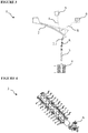
- Figure 1 conceptually shows an AFM cantilever scanning the surface, the closed-loop control system that controls operation thereof and detection optics.
- AFM is the most commonly used technology for single-molecule mechanics measurements thanks to its versatility.
- Commercially available AFM cantilevers provide force resolution of few picoNewtons (pN) in liquid.
- Cantilevers should be actuated within a specific speed range for AFM-based dynamic force spectroscopy applications. Higher dynamic range for actuation and detection is required along with higher force resolution for improved dynamic force spectroscopy.
- the pulling speed of the cantilever by using a piezo actuator determines the molecular loading rate in a conventional AFM system. Hydrodynamic drag force on the moving cantilever increases with the pulling speed.
- Drag force may reach the level of biomolecular forces, which is desired to be measured, even at moderate speed levels, i.e., a few tens of ⁇ m/s for most of the cantilevers in use. However higher pulling speed capability is required for complete understanding of energy landscapes. In the light of these, the need for novel force sensors and technologies that allow high loading rates with minimal hydrodynamic drag forces on the force sensors can be put in a proper context.
- Magnetic micro-beads are frequently used for actuating biomolecules by magnetic particles.
- the present invention which enables manipulation of biomolecules for investigating their conformational behavior with high precision along multiple degrees of freedom, is fundamentally different from the approaches used in conventional magnetic manipulation systems in which magnetic beads are used.
- the magnetic micro-beads are typically made of iron oxide particles covered by polymer matrices.
- a spherical single domain magnetite particle with a diameter of 100 nm cannot exert forces in excess of tens of picoNewtons given practical limitations on the generation of magnetic field gradients, and is incapable of generating torque due to its geometry. This is a significant limitation in their use.
- the size of the particles may be increased to increase the attainable force levels; however, surface area of magnetic particles with diameters larger than 1 ⁇ m is much larger than an area to which a single biomolecule can bind. Therefore, their use in single-molecule measurements is limited.
- High aspect ratio magnetic nanowires address this bottleneck. Magnetic nanowires exhibit larger magnetic moments as compared to the beads because of their higher volume and their inherent magnetic shape anisotropy. Upon comparing the attainable force levels, it was observed that nickel magnetic nanowires outperformed magnetic beads of the same volume by a factor of two. Moreover, when increasing the volume of nanowires, the size of its tip binding to the molecules does not have to be increased. Volume of a nanowire can be increased by extending its length while keeping its diameter small enough so that it can still interact with single molecules. Additionally, nanowires can also generate torque thanks to their geometric forms.
- the structure disclosed in United States Patent document no. US8479309B2 is a novel AFM cantilever.
- An improved measurement cantilever is produced by means of a nano-needle integrated to an AFM cantilever and it is disclosed that by means of this cantilever improvements are achieved in the measurements conducted in liquid.
- This method is aimed for developing a new cantilever, and the nano-needle arranged on the cantilever only provides a new geometry to the cantilever.
- the innovation disclosed by the biomolecular measurement system of the present invention is combination of magnetic nanowires with biomolecules and using the nanowires as actuators. In the bimolecular measurement system of the present invention, the nanowires are integral part of the measurement system and they provide magnetic actuation capability.
- the document titled " New fabrication methods and measurement techniques enable development of nanoscale bimorph actuators” (E. H. Yang, 23 June 2010, SPIE Newsroom. DOI: 10.1117/2.1201006.002602 ) presents nano-scale actuators produced with bimorph structures.
- the feature of bimorph structures is that they bend under temperature difference. By means of this feature, it is possible to exert force at micro and nano-scale.
- the nano-structures are used to exert force on biological structures.
- the nanowires used in the biomolecular measurement system of the present invention are the actuators of the AFM system.
- the nanowires described in the present invention are magnetic actuators and differ from the nano-structures of bimorph actuators in terms of both function and structure.
- the article titled " Control of tip-to-sample distance in atomic force microscopy: a dual-actuator tip-motion control scheme" (Jeong Y, Jayanth GR, Menq CH., Rev Sci Instrum. 2007 Sep;78(9):093706 ) describes actuation of a standard AFM cantilever by a magnetic particle adhered on the AFM cantilever.
- the mechanical structure moved in this system is the cantilever itself and the magnetic particle is fixed to the cantilever.
- the moving structure is nanowire whereas the cantilever is fixed.
- the cantilever moves only as a result of biomolecular interaction forces. It does not move due to the signal applied to the actuator. Thus, low noise and high stability measurements can be performed.
- the patent application document no. KR 10-2013-0060027 A discloses an AFM wherein a biomolecule is bound between the AFM tip and a magnetic nanowire.
- the AFM cantilever is moved by an actuator.
- the invention is about a biomolecular measurement system as in claim 1.
- piezotube actuators are used in AFM systems as actuators.
- the approach in the present invention is use of a nanostructure actuator miniaturized down to the size of a single macromolecule as an actuator for biomolecular measurements.
- the innovative actuation method proposed here will advance beyond the state of the art in the field of single-molecule studies.
- the implementation of the actuator will be based on a five degrees-of-freedom (three translational and two rotational) wireless magnetic manipulator.
- At the heart of the magnetic manipulator there lies a magnetic nanowire or a magnetic micro/nano-structure.
- the footprint of the actuator will be orders of magnitude smaller than the commonly used piezotubes.
- Use of miniaturized mechanical actuator improves system dynamics. It enhances resolution and stability of the system. Drift and system complexity due to a larger scale piezo actuator can be eliminated.
- an AFM cantilever is attached to a macromolecule that is already attached to a magnetic nanowire. Under the externally controlled magnetic fields and field gradients, it is possible to manipulate the molecule along multiple degrees-of-freedom without a substrate surface. Manipulation tasks with objects varying in dimensions from nanometers to centimeters with five degrees-of-freedom with high resolution that is limited by imaging technology have already been demonstrated with electromagnetic manipulation setups. Electromagnetic coils, magnets or both can be used at the same time in varying arrangements for the magnetic manipulation of objects. Using nanowires made of soft magnetic materials (e.g., Permalloy, Nickel, Iron, Cobalt or alloys comprising these materials), manipulation is accomplished using relatively small magnetic fields (a few hundreds Oe).
- soft magnetic materials e.g., Permalloy, Nickel, Iron, Cobalt or alloys comprising these materials
- a magnetic nanowire encounters drastically smaller hydrodynamic drag forces in viscous fluids as compared to larger structures.
- the drag (hence damping) on a mechanical system is an indication of thermal noise according to the fluctuation dissipation theorem. Reduced hydrodynamic drag improves force resolution significantly.
- the most important objective of the present invention is to utilize a low noise AFM system.
- the proposed method is unique in its ability to detect the slightest conformational changes on a single molecule level in contrast to the current technologies. This system promises a leap forward in characterizing proteins and probing their structure and function.
- the proposed biomolecular measurement system is capable of probing biomolecular interactions:
- a novel and improved single molecule measurement system is proposed by combining AFM technology with magnetic positioning by means of the present invention.
- Inter/intra-molecular interactions of biomolecules are investigated with high precision along multiple degrees-of-freedom at single molecule level with the new technology,.
- This objective is supported by integration of the electromagnetic nano-actuators with the molecules.
- By means of reduction of the size of the actuators to the size of molecules molecule positioning at multiple degrees-of-freedom and detection at single-molecule level are possible.
- High stability experiments can be conducted by means of the newly developed biomolecular measurement system.
- speed and manipulation capabilities of the novel actuators will enable improved AFM experiments.
- a biomolecular measurement system (1) which enables to measure the intermolecular forces arising from the interaction between two biomolecules or the intramolecular forces of a single biomolecule by using an atomic force microscope (AFM), basically comprises
- the cantilever (2) provided in the biomolecular measurement system (1) of the present invention is fixed and is not moved by any actuator.
- the cantilever (2) has a pointed cantilever tip (2.1) having a diameter that allows binding of only a single biomolecule.
- the cantilever tip (2.1) can be a tip produced from materials, such as gold, silicon, silicon nitride or silicon oxide that allow attachment of the biomolecules.
- the magnetic nanowire (3) is a cylindrical structure preferably having a length of 1 ⁇ m (micrometer) and a diameter of 100nm (nanometer).
- the end of the said magnetic nanowire (3) which is the area of attachment for the biomolecules, is made of gold or polymer, while the other parts can be made of a magnetic material, which does not bind to the molecules, preferably cobalt, iron, nickel or an alloy comprising at least one of these metals.
- the magnetic nanowire (3) acts as a magnet and can be pushed and pulled by the actuator (4) by applying a magnetic field.
- An example magnetic nanowire (3) is shown in Figure 3 .
- An actuator (4) positioned at the lower part of the magnetic nanowire (3) is used for this purpose.
- This actuator (4) may comprise at least one electromagnet, magnet, Helmhotz coil or at least one of these structures.
- the said actuator (4) is driven by a driver electronics (not shown in the figures), magnetic force is applied to the magnetic nanowire (3) by passing current through the cables wound around the core of the electromagnet, and thus the biomolecules between the cantilever tip (2.1) attached on the magnetic nanowire (3) are moved.
- the cantilever tip (2.1) and thus the cantilever (2) move at any coordinate on the x, y and z axes in the direction of the biomolecules or make a rotational movement.
- a laser source (5) and a photodetector (6) located at the upper part of the cantilever (2) are used to measure the interaction between the biomolecules.
- a split photodetector can be used as a photodetector (6), for detection of the movement of the cantilever at linear axes and a quadrature photodetector can be used for detection of the torque movement.
- the incoming light (I) coming from the laser source (5) onto the reflector surface of the cantilever (2) is projected on the photodetector (6) right in the center.
- the angle of the cantilever with respect to its neutral axis (2) changes due to the movement of the biomolecules and the light reflected from the cantilever (2) is projected not in the center but at a different region of the photodetector (6).
- the molecules can be moved at any coordinate on x, y, z axes by using the magnetic nanowires (3).
- Figure 6 (left) shows how the magnetic nanowire (3) is pulled downwards by means of the force exerted by the actuator (4) onto the nanowire (3) on y axis.
- Figure 6 (middle) shows the force exerted by the actuator (4) onto the magnetic nanowire (3) at any coordinate on x, y and z axes.
- the force on the magnetic nanowire (3) can be increased by extending the length of the magnetic nanowire (3).
- torque in least one preferably three different axes can also be applied by the actuator (4) on the magnetic nanowire (3).
- Figure 6 shows the torque applied to the magnetic nanowire (3). Applying torque on the magnetic nanowire (3) enables for example double helix DNAs to recoil.
- an actuator (4) functioning as a positioner that will be formed by electromagnets, the molecules attached between the magnetic nanowire (3) and the cantilever tip (2.1) can be pulled in different directions and torque can be applied under rotating magnetic field and angular positioning can be performed.
- the magnetic nanowire (3) can be positioned precisely in a spherical working field by means of an actuator (4) that will be formed by bringing eight electromagnets together. For this reason, molecular folding/unfolding/refolding mechanisms can be completely performed by the actuators (4) formed with the said electromagnets.
- a single biomolecule such as a protein.
- proteins unfold like a string when they take part in enzymatic interaction, and then when they are done, they refold.
- Some critical diseases occur when the proteins, after unfolding and fulfilling their function, get misfolded. For example Alzheimer is one of these diseases. If a typical protein in the brain is unfolded, carries out its function and then folds incorrectly, it cannot unfold again. Examination of this is very important in single molecule level.
- one end of the said biomolecule is attached to the magnetic nanowire (3) while the other end thereof is attached to the cantilever tip (2.1).
- the magnetic nanowire (3) is subjected to the magnetic field formed by passing current through the coils of electromagnets (4) and the magnetic nanowire (3) is moved forward and backward.
- the biomolecule at the end of the magnetic nanowire (3) is enabled to be unfolded and folded.
- the biomolecule moves the cantilever tip (2.1) when being unfolded and folded, and this movement enables the light projected by the laser (5) on the reflector surface of the cantilever (2) to be reflected at a different angle and to be projected to a position which is different from the position where the reflected light (R) is first projected on the photodetector.
- Pathways and dynamics of unfolding and folding of the biomolecule can be elucidated also by calculation of the difference of position of the light projected on the photodetector (6).
- the biomolecular measurement system (1) of the present invention thanks to not using an actuator to move the cantilever (2), a fluctuation is not created in the liquid in which the biomolecules are present. This in turn prevents the measurements from getting adversely affected.
Landscapes
- Health & Medical Sciences (AREA)
- Immunology (AREA)
- Life Sciences & Earth Sciences (AREA)
- Engineering & Computer Science (AREA)
- Chemical & Material Sciences (AREA)
- Physics & Mathematics (AREA)
- General Physics & Mathematics (AREA)
- General Health & Medical Sciences (AREA)
- Biomedical Technology (AREA)
- Molecular Biology (AREA)
- Urology & Nephrology (AREA)
- Hematology (AREA)
- Nuclear Medicine, Radiotherapy & Molecular Imaging (AREA)
- Radiology & Medical Imaging (AREA)
- Food Science & Technology (AREA)
- Cell Biology (AREA)
- Analytical Chemistry (AREA)
- Biochemistry (AREA)
- Biotechnology (AREA)
- Pathology (AREA)
- Medicinal Chemistry (AREA)
- Microbiology (AREA)
- Nanotechnology (AREA)
- Chemical Kinetics & Catalysis (AREA)
- Micromachines (AREA)
- Investigating Or Analyzing Materials By The Use Of Magnetic Means (AREA)
- Apparatus Associated With Microorganisms And Enzymes (AREA)
Description
- The present invention relates to an atomic force microscope integrated with a multiple degrees-of-freedom magnetic actuator which enables to measure interaction forces between two molecules or intramolecular forces within a single molecule, and a measurement system using magnetic nanowires and other nano structures.
- Atomic force microscopy (AFM) has become an important tool in nanoscale science and applications. A micro-sized passive cantilever structure in a general AFM arrangement is used to measure interaction forces between a sharp needle integrated with the cantilever and a surface that the needle interacts with. The cantilever is moved over the surface by the help of a piezo actuator. In the meantime, the force acting on the cantilever causes bending on the cantilever depending on its spring constant. Bending is measured by optical means.
Figure 1 conceptually shows an AFM cantilever scanning the surface, the closed-loop control system that controls operation thereof and detection optics. - AFM is the most commonly used technology for single-molecule mechanics measurements thanks to its versatility. Commercially available AFM cantilevers provide force resolution of few picoNewtons (pN) in liquid. , Cantilevers should be actuated within a specific speed range for AFM-based dynamic force spectroscopy applications. Higher dynamic range for actuation and detection is required along with higher force resolution for improved dynamic force spectroscopy. The pulling speed of the cantilever by using a piezo actuator determines the molecular loading rate in a conventional AFM system. Hydrodynamic drag force on the moving cantilever increases with the pulling speed. Drag force may reach the level of biomolecular forces, which is desired to be measured, even at moderate speed levels, i.e., a few tens of µm/s for most of the cantilevers in use. However higher pulling speed capability is required for complete understanding of energy landscapes. In the light of these, the need for novel force sensors and technologies that allow high loading rates with minimal hydrodynamic drag forces on the force sensors can be put in a proper context.
- Magnetic micro-beads are frequently used for actuating biomolecules by magnetic particles. The present invention, which enables manipulation of biomolecules for investigating their conformational behavior with high precision along multiple degrees of freedom, is fundamentally different from the approaches used in conventional magnetic manipulation systems in which magnetic beads are used. The magnetic micro-beads are typically made of iron oxide particles covered by polymer matrices. A spherical single domain magnetite particle with a diameter of 100 nm cannot exert forces in excess of tens of picoNewtons given practical limitations on the generation of magnetic field gradients, and is incapable of generating torque due to its geometry. This is a significant limitation in their use. The size of the particles may be increased to increase the attainable force levels; however, surface area of magnetic particles with diameters larger than 1 µm is much larger than an area to which a single biomolecule can bind. Therefore, their use in single-molecule measurements is limited. High aspect ratio magnetic nanowires address this bottleneck. Magnetic nanowires exhibit larger magnetic moments as compared to the beads because of their higher volume and their inherent magnetic shape anisotropy. Upon comparing the attainable force levels, it was observed that nickel magnetic nanowires outperformed magnetic beads of the same volume by a factor of two. Moreover, when increasing the volume of nanowires, the size of its tip binding to the molecules does not have to be increased. Volume of a nanowire can be increased by extending its length while keeping its diameter small enough so that it can still interact with single molecules. Additionally, nanowires can also generate torque thanks to their geometric forms.
- The International patent application document no.
WO2011029592 , an application in the state of the art, discloses a magnetic manipulation device for magnetic elements. - The structure disclosed in United States Patent document no.
US8479309B2 , an application in the state of the art, is a novel AFM cantilever. An improved measurement cantilever is produced by means of a nano-needle integrated to an AFM cantilever and it is disclosed that by means of this cantilever improvements are achieved in the measurements conducted in liquid. This method is aimed for developing a new cantilever, and the nano-needle arranged on the cantilever only provides a new geometry to the cantilever. The innovation disclosed by the biomolecular measurement system of the present invention is combination of magnetic nanowires with biomolecules and using the nanowires as actuators. In the bimolecular measurement system of the present invention, the nanowires are integral part of the measurement system and they provide magnetic actuation capability. - The document titled "New fabrication methods and measurement techniques enable development of nanoscale bimorph actuators" (E. H. Yang, 23 June 2010, SPIE Newsroom. DOI: 10.1117/2.1201006.002602) presents nano-scale actuators produced with bimorph structures. The feature of bimorph structures is that they bend under temperature difference. By means of this feature, it is possible to exert force at micro and nano-scale. The nano-structures are used to exert force on biological structures. The nanowires used in the biomolecular measurement system of the present invention are the actuators of the AFM system. The nanowires described in the present invention are magnetic actuators and differ from the nano-structures of bimorph actuators in terms of both function and structure.
- The article titled "Control of tip-to-sample distance in atomic force microscopy: a dual-actuator tip-motion control scheme" (Jeong Y, Jayanth GR, Menq CH., Rev Sci Instrum. 2007 Sep;78(9):093706) describes actuation of a standard AFM cantilever by a magnetic particle adhered on the AFM cantilever. The mechanical structure moved in this system is the cantilever itself and the magnetic particle is fixed to the cantilever. In the biomolecular measurement system of the present invention, the moving structure is nanowire whereas the cantilever is fixed. The cantilever moves only as a result of biomolecular interaction forces. It does not move due to the signal applied to the actuator. Thus, low noise and high stability measurements can be performed.
- The document titled "Electromagnetically Actuated Cantilevers Using Magnetic Micropillars for Atomic Force Microscopy" (A Fakhraee, N Shamsudhin, S Sevim, A Lindo, S Pane, O Ergeneman, H Torun, B Nelson, IEEE International Magnetics Conference, May 4-8 2014, Dresden, Germany) discloses that the cantilever is moved by the magnetic forces in an application similar to the structure described by the document titled "Control of tip-to-sample distance in atomic force microscopy: a dual-actuator tip-motion control scheme". A micropillar is adhered onto the cantilever. The actuation method formed by an electromagnet is different from the method used in the biomolecular measurement system of the present invention. In the present invention, while the cantilever remains fixed, the magnetic nanowires are actuated by the actuator signal. Furthermore, the nanowires in the present invention are much smaller than the micropillars described in the mentioned document.
- The patent application document no.
KR 10-2013-0060027 A - The invention is about a biomolecular measurement system as in claim 1.
- Usually piezotube actuators are used in AFM systems as actuators. The approach in the present invention is use of a nanostructure actuator miniaturized down to the size of a single macromolecule as an actuator for biomolecular measurements. The innovative actuation method proposed here will advance beyond the state of the art in the field of single-molecule studies. The implementation of the actuator will be based on a five degrees-of-freedom (three translational and two rotational) wireless magnetic manipulator. At the heart of the magnetic manipulator, there lies a magnetic nanowire or a magnetic micro/nano-structure. Thus the footprint of the actuator will be orders of magnitude smaller than the commonly used piezotubes. Use of miniaturized mechanical actuator improves system dynamics. It enhances resolution and stability of the system. Drift and system complexity due to a larger scale piezo actuator can be eliminated.
- An unprecedented improvement can be provided over the system dynamics by using magnetic nanowires as actuators and keeping the cantilevers fixed. In this architecture, an AFM cantilever is attached to a macromolecule that is already attached to a magnetic nanowire. Under the externally controlled magnetic fields and field gradients, it is possible to manipulate the molecule along multiple degrees-of-freedom without a substrate surface. Manipulation tasks with objects varying in dimensions from nanometers to centimeters with five degrees-of-freedom with high resolution that is limited by imaging technology have already been demonstrated with electromagnetic manipulation setups. Electromagnetic coils, magnets or both can be used at the same time in varying arrangements for the magnetic manipulation of objects. Using nanowires made of soft magnetic materials (e.g., Permalloy, Nickel, Iron, Cobalt or alloys comprising these materials), manipulation is accomplished using relatively small magnetic fields (a few hundreds Oe).
- On the nanometer scale, manipulation of different types of structures such as nanocoils, nanowires and nanotubes with different motion strategies such as gradient based translational motion and field based rotational motion have been demonstrated. Use of magnetic nanowires offers various advantages over other magnetic nanostructures. They exhibit strong geometric anisotropy due to their high aspect ratio. Therefore, in addition to linear pulling, it is possible to apply torque on the nanowires under the influence of rotating magnetic field. Complete energy landscape of the molecules can be obtained thanks to the new actuation method. Also, molecular unfolding/folding/refolding mechanisms can be investigated with an unprecedented detail and accuracy using magnetic nanoactuators. An immediate application will be elucidating folding/unfolding pathways of single protein molecules. A magnetic nanowire encounters drastically smaller hydrodynamic drag forces in viscous fluids as compared to larger structures. The drag (hence damping) on a mechanical system is an indication of thermal noise according to the fluctuation dissipation theorem. Reduced hydrodynamic drag improves force resolution significantly.
- Thus, the most important objective of the present invention is to utilize a low noise AFM system. The proposed method is unique in its ability to detect the slightest conformational changes on a single molecule level in contrast to the current technologies. This system promises a leap forward in characterizing proteins and probing their structure and function.
- The proposed biomolecular measurement system is capable of probing biomolecular interactions:
- under controlled forces and excitations with multiple degrees-of-freedom,
- at a much higher dynamic rate to elucidate the complete energy landscape of single molecular interactions, and
- at physiological rates (i.e. long time scale biophysical experiments) by reducing drift and increasing stability.
- In this architecture of this biomolecular measurement system
- magnetic nanowires are functionalized with biomolecules.
- an AFM cantilever picks biomolecules that are already anchored to nanowires.
- magnetic nanowires are actuated using one or more electromagnets or magnets that apply force and torque in multiple degrees-of-freedom,
- the interaction forces within the biomolecules or between the different types of biomolecules attached to nanowires are detected using the AFM cantilever.
- A novel and improved single molecule measurement system is proposed by combining AFM technology with magnetic positioning by means of the present invention. Inter/intra-molecular interactions of biomolecules are investigated with high precision along multiple degrees-of-freedom at single molecule level with the new technology,. This objective is supported by integration of the electromagnetic nano-actuators with the molecules. By means of reduction of the size of the actuators to the size of molecules, molecule positioning at multiple degrees-of-freedom and detection at single-molecule level are possible. High stability experiments can be conducted by means of the newly developed biomolecular measurement system. Furthermore, speed and manipulation capabilities of the novel actuators will enable improved AFM experiments. By means of the positioner that will be formed by nanowires, molecules attached between the nanowire and the lever can be pulled in different directions and torque can be applied under rotating magnetic field and angular positioning can be performed. For this reason, molecular folding/unfolding/refolding mechanisms can be completely elucidated by the actuators produced with the mentioned structures.
- Biomolecular measurement system developed to fulfill the objective of the present invention is illustrated in the accompanying figures, in which,
- Figure 1
- is a view of the atomic force microscope used in the prior art.
- Figure 2
- is a view of the biomolecular measurement system that enables measurement of interaction forces between two molecules.
- Figure 3
- is a view of the biomolecular measurement system that enables unfolding and folding of a single molecule.
- Figure 4
- is a perspective view of the nanowire.
- Figure 5
- is a view of a manipulator formed by multiple electromagnets.
- Figure 6
- is a representative view of the forces applied to the magnetic nanowire - in order to actuate a magnetic nanowire - at y axis and xyz axis respectively and the torque applied to the magnetic nanowire.
- The components in the figures are given reference numbers as follows:
- 1. Biomolecular measurement system
- 2. Cantilever
- 3. Magnetic nanowire
- 4. Actuator
- 5. Laser source
- 6. Photodetector
- R. Reflected light
- I. Incoming light
- A. Molecule A
- B. Molecule B
- A biomolecular measurement system (1), which enables to measure the intermolecular forces arising from the interaction between two biomolecules or the intramolecular forces of a single biomolecule by using an atomic force microscope (AFM), basically comprises
- at least one cantilever (2) which remains fixed and changes position only upon movement of the molecules without using any actuator,
- at least one cantilever tip (2.1) having a diameter that allows binding of a single biomolecule,
- at least one magnetic nanowire (3), to the end of which a single molecule can bind, and which enables to move the molecules,
- at least one actuator (4) which, by applying magnetic field to the magnetic nanowire (3), enables to pull and push the magnetic nanowire (3) at any coordinate on x, y, z axes and to apply torque on the magnetic nanowire (3) in two different axes,
- at least one laser source (5) which projects light on the cantilever (2),
- at least one photodetector (6) on which the light (R) reflected from the cantilever (2) is projected.
- The cantilever (2) provided in the biomolecular measurement system (1) of the present invention is fixed and is not moved by any actuator. The cantilever (2) has a pointed cantilever tip (2.1) having a diameter that allows binding of only a single biomolecule. The cantilever tip (2.1) can be a tip produced from materials, such as gold, silicon, silicon nitride or silicon oxide that allow attachment of the biomolecules.
- In a preferred embodiment of the invention, in order to measure the forces between two biomolecules (for example molecule A and molecule B), one of the biomolecules is attached to the cantilever tip (2.1) while the other biomolecule binds to the end of the magnetic nanowire (3). The magnetic nanowire (3) is a cylindrical structure preferably having a length of 1µm (micrometer) and a diameter of 100nm (nanometer). The end of the said magnetic nanowire (3), which is the area of attachment for the biomolecules, is made of gold or polymer, while the other parts can be made of a magnetic material, which does not bind to the molecules, preferably cobalt, iron, nickel or an alloy comprising at least one of these metals. Thus the magnetic nanowire (3) acts as a magnet and can be pushed and pulled by the actuator (4) by applying a magnetic field. An example magnetic nanowire (3) is shown in
Figure 3 . - In order to measure the interaction force between the biomolecules binding to the cantilever tip (2.1) and the magnetic nanowire (3) end, these biomolecules should be actuated. An actuator (4) positioned at the lower part of the magnetic nanowire (3) is used for this purpose. This actuator (4) may comprise at least one electromagnet, magnet, Helmhotz coil or at least one of these structures. The said actuator (4) is driven by a driver electronics (not shown in the figures), magnetic force is applied to the magnetic nanowire (3) by passing current through the cables wound around the core of the electromagnet, and thus the biomolecules between the cantilever tip (2.1) attached on the magnetic nanowire (3) are moved. Due to the movement of the biomolecules actuated by the actuator (4), the cantilever tip (2.1) and thus the cantilever (2) move at any coordinate on the x, y and z axes in the direction of the biomolecules or make a rotational movement.
- A laser source (5) and a photodetector (6) located at the upper part of the cantilever (2) are used to measure the interaction between the biomolecules. A split photodetector can be used as a photodetector (6), for detection of the movement of the cantilever at linear axes and a quadrature photodetector can be used for detection of the torque movement. The incoming light (I) coming from the laser source (5) onto the reflector surface of the cantilever (2) is projected on the photodetector (6) right in the center. The angle of the cantilever with respect to its neutral axis (2) changes due to the movement of the biomolecules and the light reflected from the cantilever (2) is projected not in the center but at a different region of the photodetector (6).
- The molecules can be moved at any coordinate on x, y, z axes by using the magnetic nanowires (3).
Figure 6 (left) shows how the magnetic nanowire (3) is pulled downwards by means of the force exerted by the actuator (4) onto the nanowire (3) on y axis.Figure 6 (middle) shows the force exerted by the actuator (4) onto the magnetic nanowire (3) at any coordinate on x, y and z axes. The force on the magnetic nanowire (3) can be increased by extending the length of the magnetic nanowire (3). - Thanks to use of magnetic nanowires (3) instead of magnetic spheres, in addition to the force in at least one preferably three different axes, torque in least one preferably three different axes can also be applied by the actuator (4) on the magnetic nanowire (3).
Figure 6 (right) shows the torque applied to the magnetic nanowire (3). Applying torque on the magnetic nanowire (3) enables for example double helix DNAs to recoil. By means of an actuator (4) functioning as a positioner that will be formed by electromagnets, the molecules attached between the magnetic nanowire (3) and the cantilever tip (2.1) can be pulled in different directions and torque can be applied under rotating magnetic field and angular positioning can be performed. To this end, the magnetic nanowire (3) can be positioned precisely in a spherical working field by means of an actuator (4) that will be formed by bringing eight electromagnets together. For this reason, molecular folding/unfolding/refolding mechanisms can be completely performed by the actuators (4) formed with the said electromagnets. - In another embodiment of the invention, instead of measuring the interactions between two biomolecules, it is enabled to elucidate unfolding/folding pathways and dynamics of a single biomolecule such as a protein. For example proteins unfold like a string when they take part in enzymatic interaction, and then when they are done, they refold. Some critical diseases occur when the proteins, after unfolding and fulfilling their function, get misfolded. For example Alzheimer is one of these diseases. If a typical protein in the brain is unfolded, carries out its function and then folds incorrectly, it cannot unfold again. Examination of this is very important in single molecule level.
- In order to examine the intramolecular forces of a single biomolecule, one end of the said biomolecule is attached to the magnetic nanowire (3) while the other end thereof is attached to the cantilever tip (2.1). As in the previous application, the magnetic nanowire (3) is subjected to the magnetic field formed by passing current through the coils of electromagnets (4) and the magnetic nanowire (3) is moved forward and backward. Thus the biomolecule at the end of the magnetic nanowire (3) is enabled to be unfolded and folded. The biomolecule moves the cantilever tip (2.1) when being unfolded and folded, and this movement enables the light projected by the laser (5) on the reflector surface of the cantilever (2) to be reflected at a different angle and to be projected to a position which is different from the position where the reflected light (R) is first projected on the photodetector. Pathways and dynamics of unfolding and folding of the biomolecule can be elucidated also by calculation of the difference of position of the light projected on the photodetector (6).
- In the biomolecular measurement system (1) of the present invention, thanks to not using an actuator to move the cantilever (2), a fluctuation is not created in the liquid in which the biomolecules are present. This in turn prevents the measurements from getting adversely affected.
Claims (9)
- A biomolecular measurement system (1), which enables to measure the intermolecular forces arising from the interaction between two biomolecules or the intramolecular forces of a single biomolecule by using an atomic force microscope (AFM), basically comprising,- at least one cantilever (2) which remains fixed,- at least one cantilever tip (2.1) to which a single biomolecule (A) can bind,- at least one magnetic nanowire (3) to the end of which a single biomolecule (A, B) can bind,
wherein,- the single molecule (A, B) which can bind to the end of the magnetic nanowire (3) can bind to:- the single biomolecule (A) which can bind to the cantilever tip (2.1); or- to the cantilever tip (2.1) so that the biomolecules (A, B) bound together or the single biomolecule (A) can have one end attached to the magnetic nanowire (3) and the other end attached to cantilever tip (2.1),- at least one laser source (5) which projects light on the cantilever (2),- at least one photodetector (6) on which the light (R) reflected from the cantilever (2) is projected,
and wherein- at least one actuator (4) which, by applying magnetic force to the magnetic nanowire (3), enables to pull and push the magnetic nanowire (3) on x, y, z axes, wherein- the magnetic nanowire (3) moves by means of the magnetic force exerted by the actuator (4) and enables to move the molecule which is attached to the end thereof, and- the cantilever (2) moves at any coordinate on the x, y and z axes in the direction of the biomolecules or makes a rotational movement without using any actuator, only by means of the movement of the biomolecules actuated by the actuator (4). - A biomolecular measurement system (1) according to Claim 1, characterized by the cantilever tip (2.1) which is pointed and has a radius of curvature at its apex that allows binding of only a single biomolecule.
- A biomolecular measurement system (1) according to Claim 1 or 2, characterized by the cantilever tip (2.1) which is produced from materials that allow attachment of the biomolecules, preferably gold, silicon, silicon nitride or silicon oxide.
- A biomolecular measurement system (1) according to Claim 1, characterized by the nanowire (3), whose end that is the area of attachment for the biomolecules is preferably produced from gold or polymer, and whose other parts are produced from a magnetic material which does not bind to the molecules, preferably cobalt, iron, nickel or an alloy comprising at least one of these metals.
- A biomolecular measurement system (1) according to Claim 1, characterized by at least one actuator (4) comprising at least one electromagnet, magnet, Helmhotz coil or at least one of these structures.
- A biomolecular measurement system (1) according to Claim 1 or 5, characterized by the actuator (4); which, in order to measure the interaction force between the biomolecules, one of which is attached to the cantilever tip (2.1) and the other to the magnetic nanowire (3), applies magnetic field to the magnetic nanowire (3); and thereby enables the biomolecules attached to the magnetic nanowire (3) to be moved.
- A biomolecular measurement system (1) according to Claim 4 or 5, characterized by the actuator (4) which enables to apply force in at least one preferably three different axes, and torque in least one preferably three different axes on the magnetic nanowire (3).
- A biomolecular measurement system (1) according to Claims 5 to 7, characterized by the actuator (4), which, by means of a positioner that will be formed by using a plurality of electromagnets, enables the molecules attached between the magnetic nanowire (3) and the cantilever tip (2.1) to be pulled in different directions and torque to be applied under rotating magnetic field and angular positioning to be performed.
- A biomolecular measurement system (1) according to Claim 5 to 8, characterized by the actuator (4); which; in order to measure the intramolecular force of a biomolecule, one end of which is attached to the cantilever tip (2.1) and the other end to the magnetic nanowire (3); applies magnetic field to the magnetic nanowire (3); and thereby enables the said molecule to unfold/fold.
Applications Claiming Priority (2)
| Application Number | Priority Date | Filing Date | Title |
|---|---|---|---|
| TR201409565 | 2014-08-15 | ||
| PCT/TR2015/050052 WO2016024931A1 (en) | 2014-08-15 | 2015-07-31 | An atomic force microscope integrated with a multiple degrees-of-freedom magnetic actuator |
Publications (2)
| Publication Number | Publication Date |
|---|---|
| EP3087400A1 EP3087400A1 (en) | 2016-11-02 |
| EP3087400B1 true EP3087400B1 (en) | 2019-11-13 |
Family
ID=54256813
Family Applications (1)
| Application Number | Title | Priority Date | Filing Date |
|---|---|---|---|
| EP15775521.6A Active EP3087400B1 (en) | 2014-08-15 | 2015-07-31 | An atomic force microscope integrated with a multiple degrees-of-freedom magnetic actuator |
Country Status (3)
| Country | Link |
|---|---|
| US (1) | US9645144B2 (en) |
| EP (1) | EP3087400B1 (en) |
| WO (1) | WO2016024931A1 (en) |
Cited By (1)
| Publication number | Priority date | Publication date | Assignee | Title |
|---|---|---|---|---|
| US11175307B1 (en) | 2020-08-28 | 2021-11-16 | Globalfoundries U.S. Inc. | Conductive atomic force microscopy system with enhanced sensitivity and methods of using such a system |
Families Citing this family (2)
| Publication number | Priority date | Publication date | Assignee | Title |
|---|---|---|---|---|
| US10073057B2 (en) * | 2016-06-14 | 2018-09-11 | Universidad De Santiago De Chile | Micro magnetic trap and process for evaluating forces with pico Newton resolution |
| CN109725177B (en) * | 2019-03-05 | 2020-05-22 | 西安交通大学 | A method for measuring the interfacial binding energy of one-dimensional nanomaterials |
Family Cites Families (8)
| Publication number | Priority date | Publication date | Assignee | Title |
|---|---|---|---|---|
| WO2000074107A2 (en) * | 1999-05-31 | 2000-12-07 | Evgeny Invievich Givargizov | Tip structures, devices on their basis, and methods for their preparation |
| US6583411B1 (en) * | 2000-09-13 | 2003-06-24 | Europaisches Laboratorium Für Molekularbiologie (Embl) | Multiple local probe measuring device and method |
| JP4610811B2 (en) * | 2000-09-15 | 2011-01-12 | アイメック | Probe manufacturing method and apparatus |
| US7357018B2 (en) * | 2006-02-10 | 2008-04-15 | Agilent Technologies, Inc. | Method for performing a measurement inside a specimen using an insertable nanoscale FET probe |
| WO2011029592A1 (en) | 2009-09-11 | 2011-03-17 | Eth Zurich | Magnetic manipulation and navigation system for a magnetic element |
| GB2484749B (en) * | 2010-10-20 | 2013-10-23 | Frank Michael Ohnesorge | Interatomic force measurements using passively drift-compensated non-contact in-situ calibrated atomic force microscopy - quantifying chemical bond forces |
| US8479309B2 (en) | 2011-04-28 | 2013-07-02 | The Board Of Trustees Of The University Of Illinois | Ultra-low damping imaging mode related to scanning probe microscopy in liquid |
| KR101308117B1 (en) | 2011-11-29 | 2013-09-12 | 포항공과대학교 산학협력단 | Magnetic force microscopy cantilever with a magnetic particle at the tip end and fabrication method therefor |
-
2015
- 2015-07-31 WO PCT/TR2015/050052 patent/WO2016024931A1/en not_active Ceased
- 2015-07-31 US US15/033,115 patent/US9645144B2/en not_active Expired - Fee Related
- 2015-07-31 EP EP15775521.6A patent/EP3087400B1/en active Active
Non-Patent Citations (1)
| Title |
|---|
| None * |
Cited By (1)
| Publication number | Priority date | Publication date | Assignee | Title |
|---|---|---|---|---|
| US11175307B1 (en) | 2020-08-28 | 2021-11-16 | Globalfoundries U.S. Inc. | Conductive atomic force microscopy system with enhanced sensitivity and methods of using such a system |
Also Published As
| Publication number | Publication date |
|---|---|
| EP3087400A1 (en) | 2016-11-02 |
| WO2016024931A1 (en) | 2016-02-18 |
| US9645144B2 (en) | 2017-05-09 |
| US20160266107A1 (en) | 2016-09-15 |
Similar Documents
| Publication | Publication Date | Title |
|---|---|---|
| US6828786B2 (en) | Method and apparatus for nanomagnetic manipulation and sensing | |
| Li et al. | " Videolized" atomic force microscopy for interactive nanomanipulation and nanoassembly | |
| Dong et al. | Tutorial-Robotics in the small part II: nanorobotics | |
| Von Gratowski et al. | Advanced system for nanofabrication and nanomanipulation based on shape memory alloy | |
| Kaestner et al. | Advanced electric-field scanning probe lithography on molecular resist using active cantilever | |
| US9548677B2 (en) | Microelectromechanical (MEMS) manipulators for control of nanoparticle coupling interactions | |
| Nelson et al. | Micro-/nanorobots | |
| US9645144B2 (en) | Atomic force microscope integrated with a multiple degrees-of-freedom magnetic actuator | |
| Lu et al. | Nanorobotic system for precise in situ three-dimensional manufacture of helical microstructures | |
| Mekid et al. | Nanoscale manipulators: review of conceptual designs through recent patents | |
| Mekid et al. | Engineering manipulation at nanoscale: further functional specifications | |
| Dong et al. | Engineering multiwalled carbon nanotubes inside a transmission electron microscope using nanorobotic manipulation | |
| Tseng | Three-dimensional patterning of nanostructures using atomic force microscopes | |
| Makulavicius et al. | Recent advances in mechanical micro-and nanomanipulation | |
| Fatikow et al. | Nanohandling automation: trends and current developments | |
| Kandpal et al. | Spin-coatable, photopatternable magnetic nanocomposite thin films for MEMS device applications | |
| Martel | Nanorobots for microfactories to operations in the human body and robots propelled by bacteria | |
| Jayanth et al. | Design and modeling of an active five-axis compliant micromanipulator | |
| Narendra et al. | An electromagnetically actuated ball and socket joint for applications in 3D metrology | |
| US9649763B2 (en) | Micro-nano tools with changeable tips for micro-NANO manipulation | |
| US8893311B2 (en) | Three-dimensional imaging and manipulation | |
| Punyabrahma et al. | A magnetometer for estimating the moment of magnetic micro-particle in three dimensions | |
| Meier | Magnetoresistive and Thermoresistive Scanning Probe Microscopy with Applications in Micro-and Nanotechnology | |
| Maroufi et al. | MEMS in Nanopositioning | |
| Xie et al. | Descriptions and challenges of AFM based nanorobotic systems |
Legal Events
| Date | Code | Title | Description |
|---|---|---|---|
| PUAI | Public reference made under article 153(3) epc to a published international application that has entered the european phase |
Free format text: ORIGINAL CODE: 0009012 |
|
| 17P | Request for examination filed |
Effective date: 20160331 |
|
| AK | Designated contracting states |
Kind code of ref document: A1 Designated state(s): AL AT BE BG CH CY CZ DE DK EE ES FI FR GB GR HR HU IE IS IT LI LT LU LV MC MK MT NL NO PL PT RO RS SE SI SK SM TR |
|
| AX | Request for extension of the european patent |
Extension state: BA ME |
|
| DAV | Request for validation of the european patent (deleted) | ||
| DAX | Request for extension of the european patent (deleted) | ||
| GRAP | Despatch of communication of intention to grant a patent |
Free format text: ORIGINAL CODE: EPIDOSNIGR1 |
|
| STAA | Information on the status of an ep patent application or granted ep patent |
Free format text: STATUS: GRANT OF PATENT IS INTENDED |
|
| RIC1 | Information provided on ipc code assigned before grant |
Ipc: G01Q 60/42 20100101ALI20190604BHEP Ipc: G01Q 10/04 20100101AFI20190604BHEP Ipc: G01Q 70/12 20100101ALI20190604BHEP |
|
| INTG | Intention to grant announced |
Effective date: 20190703 |
|
| RIN1 | Information on inventor provided before grant (corrected) |
Inventor name: NELSON, BRADLEY J. Inventor name: TORUN, HAMDI Inventor name: PANE I VIDAL, SALVADOR Inventor name: ERGENEMAN, OLGAC |
|
| GRAS | Grant fee paid |
Free format text: ORIGINAL CODE: EPIDOSNIGR3 |
|
| GRAA | (expected) grant |
Free format text: ORIGINAL CODE: 0009210 |
|
| STAA | Information on the status of an ep patent application or granted ep patent |
Free format text: STATUS: THE PATENT HAS BEEN GRANTED |
|
| AK | Designated contracting states |
Kind code of ref document: B1 Designated state(s): AL AT BE BG CH CY CZ DE DK EE ES FI FR GB GR HR HU IE IS IT LI LT LU LV MC MK MT NL NO PL PT RO RS SE SI SK SM TR |
|
| REG | Reference to a national code |
Ref country code: CH Ref legal event code: EP Ref country code: AT Ref legal event code: REF Ref document number: 1202236 Country of ref document: AT Kind code of ref document: T Effective date: 20191115 |
|
| REG | Reference to a national code |
Ref country code: DE Ref legal event code: R096 Ref document number: 602015041704 Country of ref document: DE |
|
| REG | Reference to a national code |
Ref country code: IE Ref legal event code: FG4D |
|
| REG | Reference to a national code |
Ref country code: CH Ref legal event code: NV Representative=s name: ARNOLD AND SIEDSMA AG, CH |
|
| REG | Reference to a national code |
Ref country code: NL Ref legal event code: MP Effective date: 20191113 |
|
| REG | Reference to a national code |
Ref country code: LT Ref legal event code: MG4D |
|
| PG25 | Lapsed in a contracting state [announced via postgrant information from national office to epo] |
Ref country code: LT Free format text: LAPSE BECAUSE OF FAILURE TO SUBMIT A TRANSLATION OF THE DESCRIPTION OR TO PAY THE FEE WITHIN THE PRESCRIBED TIME-LIMIT Effective date: 20191113 Ref country code: GR Free format text: LAPSE BECAUSE OF FAILURE TO SUBMIT A TRANSLATION OF THE DESCRIPTION OR TO PAY THE FEE WITHIN THE PRESCRIBED TIME-LIMIT Effective date: 20200214 Ref country code: PL Free format text: LAPSE BECAUSE OF FAILURE TO SUBMIT A TRANSLATION OF THE DESCRIPTION OR TO PAY THE FEE WITHIN THE PRESCRIBED TIME-LIMIT Effective date: 20191113 Ref country code: NO Free format text: LAPSE BECAUSE OF FAILURE TO SUBMIT A TRANSLATION OF THE DESCRIPTION OR TO PAY THE FEE WITHIN THE PRESCRIBED TIME-LIMIT Effective date: 20200213 Ref country code: LV Free format text: LAPSE BECAUSE OF FAILURE TO SUBMIT A TRANSLATION OF THE DESCRIPTION OR TO PAY THE FEE WITHIN THE PRESCRIBED TIME-LIMIT Effective date: 20191113 Ref country code: SE Free format text: LAPSE BECAUSE OF FAILURE TO SUBMIT A TRANSLATION OF THE DESCRIPTION OR TO PAY THE FEE WITHIN THE PRESCRIBED TIME-LIMIT Effective date: 20191113 Ref country code: BG Free format text: LAPSE BECAUSE OF FAILURE TO SUBMIT A TRANSLATION OF THE DESCRIPTION OR TO PAY THE FEE WITHIN THE PRESCRIBED TIME-LIMIT Effective date: 20200213 Ref country code: FI Free format text: LAPSE BECAUSE OF FAILURE TO SUBMIT A TRANSLATION OF THE DESCRIPTION OR TO PAY THE FEE WITHIN THE PRESCRIBED TIME-LIMIT Effective date: 20191113 Ref country code: PT Free format text: LAPSE BECAUSE OF FAILURE TO SUBMIT A TRANSLATION OF THE DESCRIPTION OR TO PAY THE FEE WITHIN THE PRESCRIBED TIME-LIMIT Effective date: 20200313 Ref country code: NL Free format text: LAPSE BECAUSE OF FAILURE TO SUBMIT A TRANSLATION OF THE DESCRIPTION OR TO PAY THE FEE WITHIN THE PRESCRIBED TIME-LIMIT Effective date: 20191113 |
|
| PG25 | Lapsed in a contracting state [announced via postgrant information from national office to epo] |
Ref country code: RS Free format text: LAPSE BECAUSE OF FAILURE TO SUBMIT A TRANSLATION OF THE DESCRIPTION OR TO PAY THE FEE WITHIN THE PRESCRIBED TIME-LIMIT Effective date: 20191113 Ref country code: IS Free format text: LAPSE BECAUSE OF FAILURE TO SUBMIT A TRANSLATION OF THE DESCRIPTION OR TO PAY THE FEE WITHIN THE PRESCRIBED TIME-LIMIT Effective date: 20200313 Ref country code: HR Free format text: LAPSE BECAUSE OF FAILURE TO SUBMIT A TRANSLATION OF THE DESCRIPTION OR TO PAY THE FEE WITHIN THE PRESCRIBED TIME-LIMIT Effective date: 20191113 |
|
| PG25 | Lapsed in a contracting state [announced via postgrant information from national office to epo] |
Ref country code: AL Free format text: LAPSE BECAUSE OF FAILURE TO SUBMIT A TRANSLATION OF THE DESCRIPTION OR TO PAY THE FEE WITHIN THE PRESCRIBED TIME-LIMIT Effective date: 20191113 |
|
| PG25 | Lapsed in a contracting state [announced via postgrant information from national office to epo] |
Ref country code: EE Free format text: LAPSE BECAUSE OF FAILURE TO SUBMIT A TRANSLATION OF THE DESCRIPTION OR TO PAY THE FEE WITHIN THE PRESCRIBED TIME-LIMIT Effective date: 20191113 Ref country code: DK Free format text: LAPSE BECAUSE OF FAILURE TO SUBMIT A TRANSLATION OF THE DESCRIPTION OR TO PAY THE FEE WITHIN THE PRESCRIBED TIME-LIMIT Effective date: 20191113 Ref country code: ES Free format text: LAPSE BECAUSE OF FAILURE TO SUBMIT A TRANSLATION OF THE DESCRIPTION OR TO PAY THE FEE WITHIN THE PRESCRIBED TIME-LIMIT Effective date: 20191113 Ref country code: RO Free format text: LAPSE BECAUSE OF FAILURE TO SUBMIT A TRANSLATION OF THE DESCRIPTION OR TO PAY THE FEE WITHIN THE PRESCRIBED TIME-LIMIT Effective date: 20191113 Ref country code: CZ Free format text: LAPSE BECAUSE OF FAILURE TO SUBMIT A TRANSLATION OF THE DESCRIPTION OR TO PAY THE FEE WITHIN THE PRESCRIBED TIME-LIMIT Effective date: 20191113 |
|
| REG | Reference to a national code |
Ref country code: DE Ref legal event code: R097 Ref document number: 602015041704 Country of ref document: DE |
|
| REG | Reference to a national code |
Ref country code: AT Ref legal event code: MK05 Ref document number: 1202236 Country of ref document: AT Kind code of ref document: T Effective date: 20191113 |
|
| PG25 | Lapsed in a contracting state [announced via postgrant information from national office to epo] |
Ref country code: SM Free format text: LAPSE BECAUSE OF FAILURE TO SUBMIT A TRANSLATION OF THE DESCRIPTION OR TO PAY THE FEE WITHIN THE PRESCRIBED TIME-LIMIT Effective date: 20191113 Ref country code: SK Free format text: LAPSE BECAUSE OF FAILURE TO SUBMIT A TRANSLATION OF THE DESCRIPTION OR TO PAY THE FEE WITHIN THE PRESCRIBED TIME-LIMIT Effective date: 20191113 |
|
| PLBE | No opposition filed within time limit |
Free format text: ORIGINAL CODE: 0009261 |
|
| STAA | Information on the status of an ep patent application or granted ep patent |
Free format text: STATUS: NO OPPOSITION FILED WITHIN TIME LIMIT |
|
| 26N | No opposition filed |
Effective date: 20200814 |
|
| PG25 | Lapsed in a contracting state [announced via postgrant information from national office to epo] |
Ref country code: SI Free format text: LAPSE BECAUSE OF FAILURE TO SUBMIT A TRANSLATION OF THE DESCRIPTION OR TO PAY THE FEE WITHIN THE PRESCRIBED TIME-LIMIT Effective date: 20191113 Ref country code: AT Free format text: LAPSE BECAUSE OF FAILURE TO SUBMIT A TRANSLATION OF THE DESCRIPTION OR TO PAY THE FEE WITHIN THE PRESCRIBED TIME-LIMIT Effective date: 20191113 |
|
| PG25 | Lapsed in a contracting state [announced via postgrant information from national office to epo] |
Ref country code: IT Free format text: LAPSE BECAUSE OF FAILURE TO SUBMIT A TRANSLATION OF THE DESCRIPTION OR TO PAY THE FEE WITHIN THE PRESCRIBED TIME-LIMIT Effective date: 20191113 |
|
| PG25 | Lapsed in a contracting state [announced via postgrant information from national office to epo] |
Ref country code: MC Free format text: LAPSE BECAUSE OF FAILURE TO SUBMIT A TRANSLATION OF THE DESCRIPTION OR TO PAY THE FEE WITHIN THE PRESCRIBED TIME-LIMIT Effective date: 20191113 |
|
| REG | Reference to a national code |
Ref country code: BE Ref legal event code: MM Effective date: 20200731 |
|
| PG25 | Lapsed in a contracting state [announced via postgrant information from national office to epo] |
Ref country code: LU Free format text: LAPSE BECAUSE OF NON-PAYMENT OF DUE FEES Effective date: 20200731 |
|
| PG25 | Lapsed in a contracting state [announced via postgrant information from national office to epo] |
Ref country code: BE Free format text: LAPSE BECAUSE OF NON-PAYMENT OF DUE FEES Effective date: 20200731 |
|
| PG25 | Lapsed in a contracting state [announced via postgrant information from national office to epo] |
Ref country code: IE Free format text: LAPSE BECAUSE OF NON-PAYMENT OF DUE FEES Effective date: 20200731 |
|
| PG25 | Lapsed in a contracting state [announced via postgrant information from national office to epo] |
Ref country code: TR Free format text: LAPSE BECAUSE OF FAILURE TO SUBMIT A TRANSLATION OF THE DESCRIPTION OR TO PAY THE FEE WITHIN THE PRESCRIBED TIME-LIMIT Effective date: 20191113 Ref country code: MT Free format text: LAPSE BECAUSE OF FAILURE TO SUBMIT A TRANSLATION OF THE DESCRIPTION OR TO PAY THE FEE WITHIN THE PRESCRIBED TIME-LIMIT Effective date: 20191113 Ref country code: CY Free format text: LAPSE BECAUSE OF FAILURE TO SUBMIT A TRANSLATION OF THE DESCRIPTION OR TO PAY THE FEE WITHIN THE PRESCRIBED TIME-LIMIT Effective date: 20191113 |
|
| PG25 | Lapsed in a contracting state [announced via postgrant information from national office to epo] |
Ref country code: MK Free format text: LAPSE BECAUSE OF FAILURE TO SUBMIT A TRANSLATION OF THE DESCRIPTION OR TO PAY THE FEE WITHIN THE PRESCRIBED TIME-LIMIT Effective date: 20191113 |
|
| PGFP | Annual fee paid to national office [announced via postgrant information from national office to epo] |
Ref country code: GB Payment date: 20220824 Year of fee payment: 8 Ref country code: DE Payment date: 20220729 Year of fee payment: 8 |
|
| PGFP | Annual fee paid to national office [announced via postgrant information from national office to epo] |
Ref country code: FR Payment date: 20220722 Year of fee payment: 8 |
|
| PGFP | Annual fee paid to national office [announced via postgrant information from national office to epo] |
Ref country code: CH Payment date: 20220808 Year of fee payment: 8 |
|
| REG | Reference to a national code |
Ref country code: DE Ref legal event code: R119 Ref document number: 602015041704 Country of ref document: DE |
|
| REG | Reference to a national code |
Ref country code: CH Ref legal event code: PL |
|
| GBPC | Gb: european patent ceased through non-payment of renewal fee |
Effective date: 20230731 |
|
| PG25 | Lapsed in a contracting state [announced via postgrant information from national office to epo] |
Ref country code: DE Free format text: LAPSE BECAUSE OF NON-PAYMENT OF DUE FEES Effective date: 20240201 Ref country code: GB Free format text: LAPSE BECAUSE OF NON-PAYMENT OF DUE FEES Effective date: 20230731 Ref country code: CH Free format text: LAPSE BECAUSE OF NON-PAYMENT OF DUE FEES Effective date: 20230731 |
|
| PG25 | Lapsed in a contracting state [announced via postgrant information from national office to epo] |
Ref country code: FR Free format text: LAPSE BECAUSE OF NON-PAYMENT OF DUE FEES Effective date: 20230731 |