EP3087270B1 - Starter engine solenoid - Google Patents
Starter engine solenoid Download PDFInfo
- Publication number
- EP3087270B1 EP3087270B1 EP14835690.0A EP14835690A EP3087270B1 EP 3087270 B1 EP3087270 B1 EP 3087270B1 EP 14835690 A EP14835690 A EP 14835690A EP 3087270 B1 EP3087270 B1 EP 3087270B1
- Authority
- EP
- European Patent Office
- Prior art keywords
- diode
- structural body
- solenoid
- starter engine
- accommodation
- Prior art date
- Legal status (The legal status is an assumption and is not a legal conclusion. Google has not performed a legal analysis and makes no representation as to the accuracy of the status listed.)
- Active
Links
Images

Classifications
-
- H—ELECTRICITY
- H01—ELECTRIC ELEMENTS
- H01F—MAGNETS; INDUCTANCES; TRANSFORMERS; SELECTION OF MATERIALS FOR THEIR MAGNETIC PROPERTIES
- H01F7/00—Magnets
- H01F7/06—Electromagnets; Actuators including electromagnets
- H01F7/08—Electromagnets; Actuators including electromagnets with armatures
-
- F—MECHANICAL ENGINEERING; LIGHTING; HEATING; WEAPONS; BLASTING
- F02—COMBUSTION ENGINES; HOT-GAS OR COMBUSTION-PRODUCT ENGINE PLANTS
- F02N—STARTING OF COMBUSTION ENGINES; STARTING AIDS FOR SUCH ENGINES, NOT OTHERWISE PROVIDED FOR
- F02N15/00—Other power-operated starting apparatus; Component parts, details, or accessories, not provided for in, or of interest apart from groups F02N5/00 - F02N13/00
- F02N15/006—Assembling or mounting of starting devices
-
- F—MECHANICAL ENGINEERING; LIGHTING; HEATING; WEAPONS; BLASTING
- F02—COMBUSTION ENGINES; HOT-GAS OR COMBUSTION-PRODUCT ENGINE PLANTS
- F02N—STARTING OF COMBUSTION ENGINES; STARTING AIDS FOR SUCH ENGINES, NOT OTHERWISE PROVIDED FOR
- F02N11/00—Starting of engines by means of electric motors
- F02N11/08—Circuits specially adapted for starting of engines
- F02N11/0859—Circuits specially adapted for starting of engines specially adapted to the type of the starter motor or integrated into it
-
- F—MECHANICAL ENGINEERING; LIGHTING; HEATING; WEAPONS; BLASTING
- F02—COMBUSTION ENGINES; HOT-GAS OR COMBUSTION-PRODUCT ENGINE PLANTS
- F02N—STARTING OF COMBUSTION ENGINES; STARTING AIDS FOR SUCH ENGINES, NOT OTHERWISE PROVIDED FOR
- F02N15/00—Other power-operated starting apparatus; Component parts, details, or accessories, not provided for in, or of interest apart from groups F02N5/00 - F02N13/00
- F02N15/10—Safety devices not otherwise provided for
-
- F—MECHANICAL ENGINEERING; LIGHTING; HEATING; WEAPONS; BLASTING
- F02—COMBUSTION ENGINES; HOT-GAS OR COMBUSTION-PRODUCT ENGINE PLANTS
- F02N—STARTING OF COMBUSTION ENGINES; STARTING AIDS FOR SUCH ENGINES, NOT OTHERWISE PROVIDED FOR
- F02N11/00—Starting of engines by means of electric motors
-
- F—MECHANICAL ENGINEERING; LIGHTING; HEATING; WEAPONS; BLASTING
- F02—COMBUSTION ENGINES; HOT-GAS OR COMBUSTION-PRODUCT ENGINE PLANTS
- F02N—STARTING OF COMBUSTION ENGINES; STARTING AIDS FOR SUCH ENGINES, NOT OTHERWISE PROVIDED FOR
- F02N11/00—Starting of engines by means of electric motors
- F02N11/08—Circuits specially adapted for starting of engines
- F02N11/0862—Circuits specially adapted for starting of engines characterised by the electrical power supply means, e.g. battery
-
- F—MECHANICAL ENGINEERING; LIGHTING; HEATING; WEAPONS; BLASTING
- F02—COMBUSTION ENGINES; HOT-GAS OR COMBUSTION-PRODUCT ENGINE PLANTS
- F02N—STARTING OF COMBUSTION ENGINES; STARTING AIDS FOR SUCH ENGINES, NOT OTHERWISE PROVIDED FOR
- F02N11/00—Starting of engines by means of electric motors
- F02N11/10—Safety devices
-
- F—MECHANICAL ENGINEERING; LIGHTING; HEATING; WEAPONS; BLASTING
- F02—COMBUSTION ENGINES; HOT-GAS OR COMBUSTION-PRODUCT ENGINE PLANTS
- F02N—STARTING OF COMBUSTION ENGINES; STARTING AIDS FOR SUCH ENGINES, NOT OTHERWISE PROVIDED FOR
- F02N15/00—Other power-operated starting apparatus; Component parts, details, or accessories, not provided for in, or of interest apart from groups F02N5/00 - F02N13/00
- F02N15/02—Gearing between starting-engines and started engines; Engagement or disengagement thereof
-
- F—MECHANICAL ENGINEERING; LIGHTING; HEATING; WEAPONS; BLASTING
- F02—COMBUSTION ENGINES; HOT-GAS OR COMBUSTION-PRODUCT ENGINE PLANTS
- F02N—STARTING OF COMBUSTION ENGINES; STARTING AIDS FOR SUCH ENGINES, NOT OTHERWISE PROVIDED FOR
- F02N15/00—Other power-operated starting apparatus; Component parts, details, or accessories, not provided for in, or of interest apart from groups F02N5/00 - F02N13/00
- F02N15/02—Gearing between starting-engines and started engines; Engagement or disengagement thereof
- F02N15/04—Gearing between starting-engines and started engines; Engagement or disengagement thereof the gearing including disengaging toothed gears
- F02N15/06—Gearing between starting-engines and started engines; Engagement or disengagement thereof the gearing including disengaging toothed gears the toothed gears being moved by axial displacement
- F02N15/067—Gearing between starting-engines and started engines; Engagement or disengagement thereof the gearing including disengaging toothed gears the toothed gears being moved by axial displacement the starter comprising an electro-magnetically actuated lever
-
- F—MECHANICAL ENGINEERING; LIGHTING; HEATING; WEAPONS; BLASTING
- F02—COMBUSTION ENGINES; HOT-GAS OR COMBUSTION-PRODUCT ENGINE PLANTS
- F02N—STARTING OF COMBUSTION ENGINES; STARTING AIDS FOR SUCH ENGINES, NOT OTHERWISE PROVIDED FOR
- F02N11/00—Starting of engines by means of electric motors
- F02N11/08—Circuits specially adapted for starting of engines
- F02N2011/0881—Components of the circuit not provided for by previous groups
Definitions
- the present invention relates to a diode accommodation core, particularly developed for use in solenoid of starter engines used in automotive vehicles. More preferably, the diode accommodation core, object of the present invention, comprises technical, constructive and functional aspects totally innovative and that are able to get a simple, practical, and highly e solution regarding the installation and accommodation of the diodes in the solenoids without thereby affect the structural configuration of the diodes or the structures of starter engines.
- starter engines also called starters
- starters are formed by a structure comprised basically of a cooperating solenoid with an actuating lever which in turn moves the sprocket or freewheel to connect to the crankshaft of the combustion engine.
- the actuation of these mechanisms occurs through the power supply from the moment the automotive vehicle's driver rotates the key, triggers the start button on the vehicle dashboard or the vehicle's ECU activates the actuation.
- the solenoid receives an electrical signal through the engine driving terminal thereof, which is also called “borne #50" in order to trigger the coils of said solenoid and, thus, generate a magnetic field that pulls the solenoid armature, dragging the driving lever of the starter engine.
- said actuating lever pushes the sprocket or freewheel to connect in the crankshaft gear and at the same time, the solenoid closes the electrical contact of the main circuit and starts to energize the coil and armature of the starter engine, producing a magnetic field and consequently the engine rotational motion with enough torque and speed so that the crankshaft can drive the combustion engine.
- Another solution available in the prior art comprises a combination of welding and locking by crimping the diode terminals with the solenoid structure. More specifically, this way of inserting and installing said diode consists of crimping one of the diode terminals with the male bracket of borne #50, and the other terminal is welded in the magnetic core of the solenoid. It is noted that, although functional until the present days, this solution still shows a bit complicated and can be improved and / or optimized, in particular as to the manufacturing process to ensure proper positioning of the respective electrical contacts.
- the diode accommodation core object of the present invention is yet intended to also eliminate the need for processes that lead to high manufacturing costs, for example crimping, machining, welding, or other similar manufacturing processes, which ultimately compromise the production lines and the solenoid assembly to starter engines.
- one of the main objectives of the present invention is to propose a diode accommodation core, especially for solenoids of starter engines, consisting of technical aspects developed to facilitate the manufacturing and assembly process of the solenoids, but mainly to ensure the positioning of the terminals by conducting electrical connection by pressure, without requiring adjustments in the geometric structure of the solenoids currently available on the market, or the obligatory use of welding and / or assembly additional processes.
- the present invention relates to a starter engine solenoid according to claim 1, which comprises a core for diode accommodation, as defined in claim 1, being comprised of a structural body having an opening where the body of the diode can be accommodated, and also has two contact sides which are opposite to each other, and each of them is provided with accommodation guide of the respective terminals of the diode, which has a surface portion in which at least one of said terminals is supported and at least partially exposed in relation to the surface of the corresponding contact side of the structural body, so as to promote the electrical contact with at least one adjacent component by pressure.
- the object of the present invention comprises a terminal supported and at least partially exposed to the surface of the corresponding contact side of the structural chorus, while the other terminal is crimped to the surface of the corresponding contact side of the structural body, or connected to the same by interference or other appropriate means; alternatively both terminals may remain supported and at least partially exposed regarding the surface of the corresponding contact side of the structural body.
- each of the accommodation guides extends from said opening and they are formed by an upward portion which is inclined toward the surface of the respective contact side, and by said surface portion.
- the diode accommodation core comprises accommodating tabs extending from said opening, and which are formed only by a surface portion arranged on the surface of the corresponding contact side of the structural body.
- said structural body of the diode accommodation core comprises a tablet shape.
- the opening provided in the structural body of the diode accommodation core according to the present invention has slots for the passage of the diode contact terminals, said slots being in communication with said accommodation guide arranged in each contact side of the structural body.
- said structural body of the diode accommodation core is manufactured in a flexible and insulating material. More preferably, it can be manufactured in a material selected from rubber, silicone, plastics and other insulating polymers. In particular, attention is drawn to the fact that at least the surface of the contact sides of the structural body must be covered with an insulating material.
- said structural body may comprise at least one locking portion whose purpose is to promote fitting into respective openings or slots already provided in the solenoid cover. More advantageously, with regard to fixing and adhesion, said locking portions are provided with ribs.
- the surface portions of the accommodating guides of the structural body comprise a channel profile to ensure proper positioning of the diode terminals.
- said structural body of the diode accommodation core according to the present invention comprises a shape corresponding to the screw head shape, more preferably, comprises an hexagonal shape.
- said opening may be positioned in the center of the structural body, or optionally in an asymmetric or decentralized manner.
- the diode accommodation core object of the present invention is preferably applied to starter engines (M), which are made of a structure comprising essentially a solenoid (S) which cooperates with a driving lever (A) which, in turn, moves the sprocket or freewheel (R) for connection to the combustion engine.
- S solenoid
- A driving lever
- R freewheel
- said solenoid (S) comprises a cover (T) where the bornes of electrical contact are positioned, including borne #50 (B) that is fixed with the body of the cover (T) through screw (P).
- said cover (T) is fitted with the solenoid body (S) in order to press the magnetic core (N), forming between the screw head (P) and said magnetic core (N) a space (E) which is currently totally free of any material.
- Figure 2C shows more clearly that space (E) between the screw head (P) and the surface of the magnetic core (N), the diode accommodation core object of the present invention is preferably inserted and positioned in this space (E).
- the diode accommodation core comprises a structural body 1, preferably in tablet form, provided with opening 2 for accommodating the body 4 of the diode (D) and two contact sides 3a and 3b opposing each other, each provided with accommodation guide 5', 5" of the respective terminal 6', 6" of diode (D).
- each accommodation guide 5', 5" extends from said opening 2, and can be formed by an rising portion 7, which is inclined toward the surface of the respective contact side 3a or 3b, and a surface portion 8 in which said terminal 6', 6" is supported and at least partially exposed regarding the surface of the corresponding contact side 3a or 3b of the structural body 1.
- This configuration of the accommodation guides 5' 5" is preferred in the case of the diode (D) be horizontally accommodated in the opening 2, i.e. parallel to said contact sides 3a and 3b in order to promote electrical contact with at least one adjacent component by pressure, and therefore, without requiring the welding of components. Note that such a construction discloses a single part capable of promoting pressure connection, significantly in a more simple, practical and efficient manner than that achieved with the use of similar known ones.
- FIGS 5A, 5B and 5C show in more detail the configuration and arrangement of said diode (D) properly embedded and accommodated in the diode accommodation core object of the present invention. More particularly, it can be seen that body 4 of the diode (D) is accommodated in opening 2 of structural body 1, and the respective contact terminals 6', 6" are folded and rested on respective accommodation guides 5', 5" of each contact side 3a and 3b of structural body 1. As can be seen, by this arrangement it is possile to ensure that said contact terminals 6', 6" remain separated and primarily isolated from one another, each contact terminal 6', 6" is positioned in one of said contact sides 3a, 3b of structural body 1.
- the contact terminal 6" is positioned on the accommodation guide 5" provided in said side 3b of the structural body 1, therewith, when the diode is allocated in the accommodation core, and side 3b positioned adjacent / on the head of screw (P), it is ensured that there will be contact between the head of screw (P) and diode (D) due to the terminal portion (6") be accommodated in the surface portion (8).
- terminal contact 6' is positioned on accommodation guide 5' provided in side 3a of structural body 1 so that, when the diode is allocated in the accomodation core, and side 3a positioned adjacent to magnetic core (N), it can ensure contact between magnetic core (N) and diode (D) due to terminal portion (6') be accommodated in surface portion (8) of contact side 3a.
- diode (D) With borne #50 and said electrical ground reference, in this case magnetic core (N), without the need for any soldering or crimping process.
- diode accomodation core more specifically structural body 1, that is comprised by opening 2 for receiving body 4 of diode (D), wherein said opening 2 has slots 9 for the passage of contact terminals 6', 6" of the diode (D), to enable folding and support of these terminals on accomodation guides 5', 5", particularly, positioning such terminals 6', 6' on rising portions 7 and, in sequence, on surface portions 8.
- said structural body 1 of the diode accommodation core is manufactured in a flexible and insulating material, and which is mainly susceptible to partial deshaping when subjected to pressure when coupling the cover (T) in the body of the solenoid (S).
- this material may be selected from rubber, silicone, plastics and other insulating polymers. More particularly, it should be clear that at least the surface of the contact sides 3a and 3b should be coated or consists of an insulating material.
- the structural body 1of the diode accommodating core according to the present invention may also comprise a locking portion 10 whose purpose is to penetrate and fit into openings or grooves provided in the cover (T) of the solenoid (S).
- this locking portion 10 can comprise different arrangements, since it should correspond to the formed and geometrical characteristics of cover (T).
- this locking portion 10 can comprise ribs 11 which enhance the flexibility, but improve the adhesion with the surface of the cover (T).
- Figures 7A, 7B, 8A, 8B , 9, 10A, 10B, 11A, 11B show in more detail the characteristics of the diode accommodation core, according to a possible embodiment of the present invention, in which case the structural body 1 comprises two locking portions 10, one smooth and the other with a series of ribs 11 to ensure the perfect fit and keep the same with the cover. It is noted that the geometrical arrangement of this embodiment is designed to meet the shape and configuration of cover (T) of solenoid (S), in which there is provision for a hole and space around the head of screw (P) of borne #50 (B).
- Figures 12, 13A and 13B show another constructive embodiment of structural body 1 of the diode accommodation core according to the present invention. More particularly, in this case, it appears that there is only one locking portion 10, which is provided with a series of ribs 11 to promote proper adhesion of structural body 1 with cover (T). Further, it is noted that said cap (T) comprises a region whose geometry corresponds to locking portion 10, allowing the frame body 1 with the diode thereof (D) to be embedded in cover (T) without occupying or disrupting the operation of other components of solenoid (S).
- structural body 1 and the possible locking portions 10 thereof are designed to meet the needs and settings of each solenoid model, and more particularly to each model of cover (T) of solenoids (S).
- said surface portions 8 of accommodation guides 5', 5" may comprise a channel profile, in order to ensure the positioning of contact terminals 6', 6" of diode (D), thereby avoiding any risk of diode (D) to move and provide eventual contact failures.
- said structural body 1 comprises a hexagonal shape, since the vast majority of the solenoid models known in the current market has a borne #50 fixed by a standard screw of hexagonal head type - M6, and thus it is possible to accommodate said core in space (E) generated between screw (P) and magnetic core (C) of solenoid (S). Therefore, the shape of structural body 1 depends on the solution used in the cover of solenoid (S) which provides space (E) between the connection of borne #50 and magnetic core (N), not being necessarily hexagonal.
- the diode accommodation core is able to promote a series of advantages and technical, practical and functional benefits, eliminating process steps which are complex, expensive and difficult to perform.
- terminals 6', 6" of diode (D) are separated and insulated from each other without providing any risk of contact between them and hence it is eliminated eventual risk of failure in the operation of the diode and, as a result, one can reduce the problems and inconveniences generated by the electrical pulses generated by the energizing and de-energizing the solenoid coils.
- the diode accommodation core object of the present invention can achieve as practical results the proper support of diode (D), and at the same time, ensures that the terminals of said diode (D) are pressed against the contact of borne #50 and the electrical ground reference, more preferably, through contact with the head of screw (P) and magnetic core (N) of solenoid (S).
Landscapes
- Engineering & Computer Science (AREA)
- Chemical & Material Sciences (AREA)
- Combustion & Propulsion (AREA)
- Mechanical Engineering (AREA)
- General Engineering & Computer Science (AREA)
- Physics & Mathematics (AREA)
- Electromagnetism (AREA)
- Power Engineering (AREA)
- Electromagnets (AREA)
Description
- The present invention relates to a diode accommodation core, particularly developed for use in solenoid of starter engines used in automotive vehicles. More preferably, the diode accommodation core, object of the present invention, comprises technical, constructive and functional aspects totally innovative and that are able to get a simple, practical, and highly eficiente solution regarding the installation and accommodation of the diodes in the solenoids without thereby affect the structural configuration of the diodes or the structures of starter engines.
- According to the prior art, and as should be within the common knowledge among the skilled ones in the art, starter engines, also called starters, are formed by a structure comprised basically of a cooperating solenoid with an actuating lever which in turn moves the sprocket or freewheel to connect to the crankshaft of the combustion engine. The actuation of these mechanisms occurs through the power supply from the moment the automotive vehicle's driver rotates the key, triggers the start button on the vehicle dashboard or the vehicle's ECU activates the actuation.
- More particularly, at the time of starting the engine combustion of automotive vehicles, the solenoid receives an electrical signal through the engine driving terminal thereof, which is also called "borne #50" in order to trigger the coils of said solenoid and, thus, generate a magnetic field that pulls the solenoid armature, dragging the driving lever of the starter engine. At this time, said actuating lever pushes the sprocket or freewheel to connect in the crankshaft gear and at the same time, the solenoid closes the electrical contact of the main circuit and starts to energize the coil and armature of the starter engine, producing a magnetic field and consequently the engine rotational motion with enough torque and speed so that the crankshaft can drive the combustion engine.
- From the moment the combustion engine can move alone, the electrical signal applied to borne #50 of the solenoid can be stopped and, with it, the coils are no longer energized and the sprocket or freewheel is, then disengaged from the crankshaft gear, usually through the action of a spring arranged to ensure that decoupling.
- Some time ago it was noticed that at the time the electrical signal at said borne #50 was stopped, electrical pulses were generated due to the inductance properties of the solenoid's coils, these electrical pulses being harmful to the electrical system of automotive vehicles, affecting the operation of the equipment and electrical and electronic components.
- Thus, in order to solve and / or minimize these drawbacks related to the electrical pulses, the starter engine manufacturers began to install a voltage suppressor diode with the solenoid, particularly in a parallel connection with the coils, in order to limit said electrical pulses in more acceptable values and levels to reduce risks and damage to the electrical system of the automotive vehicle.
- Thus, it is known in the art a variety of ways for inserting, positioning and installing the suppressor diode with the structure of the solenoid, which must necessarily be connected in one side to the borne #50 and in the other side with an electrical ground reference which may be, for example, the housing or the magnetic core of the solenoid.
- One of the ways known in the prior art consists of providing brackets welded to the terminals of the diodes, which are used to fixture and contact with the respective electrical contacts of the solenoid. This solution does not seem practical and simple, since it is necessary to weld the diodes terminals together with said brackets and then insert and install them in the solenoid structure, the assembly process is therefore complex and the costs involved are increased. An example of this solution can be seen in document
JP2008196373 US6148781-A ,US2012105179-A1 andJP2008166649-A - Another solution available in the prior art comprises a combination of welding and locking by crimping the diode terminals with the solenoid structure. More specifically, this way of inserting and installing said diode consists of crimping one of the diode terminals with the male bracket of borne #50, and the other terminal is welded in the magnetic core of the solenoid. It is noted that, although functional until the present days, this solution still shows a bit complicated and can be improved and / or optimized, in particular as to the manufacturing process to ensure proper positioning of the respective electrical contacts.
- Additionally, it is also known in the state of the art solutions in which the welds are eliminated, preserving only the locking bycrimping of the diode terminals with the respective contacts, that is, folding and crimping the diode terminals on borne #50 and the magnetic core of the solenoid. However, it is noted that this process is very complex and quite difficult to be realized in the practice, since, as should be appreciated by those skilled in the art, there is no space available on the solenoid structure for handling and crimping of the diode terminals and consequently, there is a great difficulty in obtaining the correct and secure positioning of this diode, without risk of release.
- Thus, as can be seen, the ways known in the state of the art for application and installation of suppressor diodes on solenoids of starter engines disclose relatively complex solutions, require additional structural elements or substantial adjustments in the structure of the solenoid as a whole. Further, it is noted that these solutions can even result in damage to other components of the solenoid, or the starter engine itself, due to the difficulty and complexity of the insertion and installation process of these diodes.
- More particularly, it is confirmed that the solutions proposed and known until the present days use welds or locking by crimping, said means can affect and damage the diodes and the solenoid. In a clear manner, the welding process is relatively dangerous to the diodes, given that the high temperatures required to promote the weld can damage the inner structure of the diodes. However, the locking by crimping process requires additional components and parts to support and lock the terminals and also to use as connectors of the diodes.
- It should be noted, therefore, that both forms of attachment and installation of the diodes face serious difficulties due to the space available for handling the involved elements and, as a consequence, they sacrifice the fixture quality and the contact level required to reduce and / or eliminate the problems generated by electrical pulses coming from the energizing and de-energizing of the starter engine coils.
- Thus, before all the above reported, it can be noted that the means for insertion and installation of suppressor diodes in starter engines for automotive vehicles known in the prior art have problems, inconveniences and restrictions for proper accommodation of the diode, as well as regarding the safe arrangement of the terminals thereof. More specifically, it is noted that the current state of the art lacks solutions able to effectively eliminate the use of weld-type harmful media as well as additional components and elements to promote the locking by crimping.
- It is therefore an object of the present invention to provide a diode accommodation core, particularly for use in solenoid of starter engines used in automotive vehicles, being comprised of technical, structural and functional features specially developed to solve, in a simple, efficient and economical manner, the limitations and drawbacks disclosed by the various forms known in the diodes insertion and installation technique in solenoids of starter engines.
- More preferably, it is an object of the present invention to provide a diode accommodation core whose characteristics have been designed to further simplify the diodes insertion and installation process with the solenoids structures, eliminating to the maximum extent the need to use locking by crimping, and especially the use of welds.
- It is also one of the objectives of the present invention to provide a diode accommodation core which allows to use the geometries and the spaces currently available in the structural components of the solenoid, thus avoiding the need for adjustments and / or modifications that may somehow affect the production lines of the starter engines.
- It is yet another among the objectives of the present invention to provide a diode accommodation core, which configuration allows to position in a safe and appropriate manner the diode contact terminals, isolating them from each other, and ensuring that each terminal stay in touch, respectively, with the fixture screw of borne #50, and with the electrical ground reference.
- The diode accommodation core object of the present invention is yet intended to also eliminate the need for processes that lead to high manufacturing costs, for example crimping, machining, welding, or other similar manufacturing processes, which ultimately compromise the production lines and the solenoid assembly to starter engines.
- Therefore, in summary, it is possible to say that one of the main objectives of the present invention is to propose a diode accommodation core, especially for solenoids of starter engines, consisting of technical aspects developed to facilitate the manufacturing and assembly process of the solenoids, but mainly to ensure the positioning of the terminals by conducting electrical connection by pressure, without requiring adjustments in the geometric structure of the solenoids currently available on the market, or the obligatory use of welding and / or assembly additional processes.
- Thus, in order to achieve the objectives and technical effects stated above, the present invention relates to a starter engine solenoid according to
claim 1, which comprises a core for diode accommodation, as defined inclaim 1, being comprised of a structural body having an opening where the body of the diode can be accommodated, and also has two contact sides which are opposite to each other, and each of them is provided with accommodation guide of the respective terminals of the diode, which has a surface portion in which at least one of said terminals is supported and at least partially exposed in relation to the surface of the corresponding contact side of the structural body, so as to promote the electrical contact with at least one adjacent component by pressure. - Optionally, the object of the present invention comprises a terminal supported and at least partially exposed to the surface of the corresponding contact side of the structural chorus, while the other terminal is crimped to the surface of the corresponding contact side of the structural body, or connected to the same by interference or other appropriate means; alternatively both terminals may remain supported and at least partially exposed regarding the surface of the corresponding contact side of the structural body.
- More preferably, each of the accommodation guides extends from said opening and they are formed by an upward portion which is inclined toward the surface of the respective contact side, and by said surface portion.
- Optionally, according to a variant embodiment of the present invention in which the diode can be positioned at an angle in said opening, the diode accommodation core comprises accommodating tabs extending from said opening, and which are formed only by a surface portion arranged on the surface of the corresponding contact side of the structural body.
- According to a possible embodiment of the present invention, said structural body of the diode accommodation core comprises a tablet shape.
- Preferably, the opening provided in the structural body of the diode accommodation core according to the present invention has slots for the passage of the diode contact terminals, said slots being in communication with said accommodation guide arranged in each contact side of the structural body.
- According to preferred embodiments of the present invention, said structural body of the diode accommodation core is manufactured in a flexible and insulating material. More preferably, it can be manufactured in a material selected from rubber, silicone, plastics and other insulating polymers. In particular, attention is drawn to the fact that at least the surface of the contact sides of the structural body must be covered with an insulating material.
- Optionally, and in accordance with the solenoid model used, said structural body may comprise at least one locking portion whose purpose is to promote fitting into respective openings or slots already provided in the solenoid cover. More advantageously, with regard to fixing and adhesion, said locking portions are provided with ribs.
- Additionally, according to advantageous embodiment of the present invention, the surface portions of the accommodating guides of the structural body comprise a channel profile to ensure proper positioning of the diode terminals.
- Further, according to one advantageous embodiment preferably nowadays, said structural body of the diode accommodation core according to the present invention, comprises a shape corresponding to the screw head shape, more preferably, comprises an hexagonal shape.
- Finally, according to other possible embodiments of the diode accommodating core of the present invention, said opening may be positioned in the center of the structural body, or optionally in an asymmetric or decentralized manner.
- The features, advantages and technical effects of the present invention, as outlined above, will be best understood by one skilled in the art from the following detailed description, made merely by way of example, and not limitation, of preferred embodiments, and with reference to the appended schematic figures, which:
-
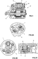
Figure 1 illustrates a sectional view of a conventional starter engine for automotive vehicles; -
Figure 2A illustrates a perspective view of the solenoid cover of a starter engine, as shown inFigure 1 ; -
Figure 2B illustrates a top view of the solenoid cover as shown inFigure 2A ; -
Figure 2C illustrates an enlarged sectional view according to the lines C-C shown in solenoid cover illustrated inFigure 2B ; -
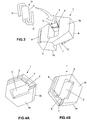
Figure 3 illustrates an exploded perspective view of the diode accommodation core according to the present invention, with the suppressor diode uncoupled; -
Figures 4A and 4B illustrate perspective views of the diode accommodation core object of the present invention in different viewing angles; -
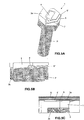
Figure 5A shows a perspective view of the diode accommodation core according to the present invention, positioned on the fixture screw of borne #50 of the solenoid; and -
Figure 5B shows an enlarged view of the detail of the diode contact terminal touching the surface of the fixture screw of borne #50 according to the present invention; -
Figure 5C shows another enlarged view of the detail of the other diode contact terminal touching the surface of the magnetic core of the solenoid according to the present invention; -
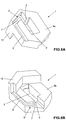
Figures 6A and 6B show perspective views, from opposite sides, of a constructive embodiment of the diode accommodation core object of the present invention; -
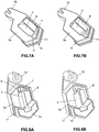
Figures 7A and 7B illustrate perspective views of another constructive embodiment of the diode accommodation core according to the present invention, with and without the suppressor diode, respectively; -
Figures 8A and 8B illustrate perspective views of opposite sides to those illustrated inFigures 7A and 7B , of the diode accommodation core according to the present invention, with and without the suppressor diode, respectively; -
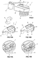
Figure 9 shows a perspective view of another possible embodiment of the diode accommodation core, according to the present invention; -
Figure 10A illustrates a perspective view of the diode accommodation core perspective according to the invention, with said diode uncoupled; -
Figure 10B illustrates a perspective view of the diode accomodation core similar toFigure 10A , but with said diode coupled; -
Figures 11A and 11B illustrate perspective views of a solenoid cover according to the present invention with and without the diode accommodation core, respectively; -
Figure 12 shows a perspective view of another alternative embodiment of the diode accommodation core according to the present invention; -
Figures 13A and 13B illustrate perspective views of a solenoid cover according to the present invention without and with the coupled diode accommodation core, respectively. - According to the schematic figure indicated above, some examples of possible and preferred embodiments of the present invention will be described in more detail below, but it should be clear that this is a purely exemplary and nonlimiting description, since this diode accommodation core can have different details and structural and dimensional aspects without thereby being out of the scope of protection.
- Additionally, it is noteworthy that some references indicative of the features of the present invention will not be fully reproduced in all the above mentioned figures, considering that the reproduction of all references in all the figures could affect the understanding and definition of the present scope of protection.
- In accordance with the accompanying drawings, particularly with reference to
Figures 1, 2A, 2B and 2C , it is seen that the diode accommodation core object of the present invention is preferably applied to starter engines (M), which are made of a structure comprising essentially a solenoid (S) which cooperates with a driving lever (A) which, in turn, moves the sprocket or freewheel (R) for connection to the combustion engine. The actuation and operation of these components is well known to those skilled in the art and was also briefly noted above, reason for which it is believed that it is unnecessary to go into detail again. - In this regard, it is noted that said solenoid (S) comprises a cover (T) where the bornes of electrical contact are positioned, including borne #50 (B) that is fixed with the body of the cover (T) through screw (P).
- Additionally, it is noted that said cover (T) is fitted with the solenoid body (S) in order to press the magnetic core (N), forming between the screw head (P) and said magnetic core (N) a space (E) which is currently totally free of any material.
Figure 2C shows more clearly that space (E) between the screw head (P) and the surface of the magnetic core (N), the diode accommodation core object of the present invention is preferably inserted and positioned in this space (E). - Thus, referring now to the other figures, and particularly to
Figures 3, 4A and 4B , it is noted that the diode accommodation core according to the present invention comprises astructural body 1, preferably in tablet form, provided withopening 2 for accommodating thebody 4 of the diode (D) and twocontact sides accommodation guide 5', 5" of therespective terminal 6', 6" of diode (D). - More specifically, each
accommodation guide 5', 5" extends from saidopening 2, and can be formed by an risingportion 7, which is inclined toward the surface of therespective contact side surface portion 8 in which saidterminal 6', 6" is supported and at least partially exposed regarding the surface of thecorresponding contact side structural body 1. This configuration of the accommodation guides 5' 5" is preferred in the case of the diode (D) be horizontally accommodated in theopening 2, i.e. parallel to saidcontact sides - It should be noted that although the preferred embodiment illustrated in the appended figures shows that in both
terminals 6', 6" the electrical contact is made by pressing of the components, it is possible that only one terminal 6' acts under pressure and thecomplementary terminal 6" acts by crimping, or vice versa, without thereby standing out of the scope of protection required here. Alternatively, it is possible to perform the electrical contact of the complementary terminal by interference assembly or other suitable technique available. -
Figures 5A, 5B and 5C show in more detail the configuration and arrangement of said diode (D) properly embedded and accommodated in the diode accommodation core object of the present invention. More particularly, it can be seen thatbody 4 of the diode (D) is accommodated inopening 2 ofstructural body 1, and therespective contact terminals 6', 6" are folded and rested on respective accommodation guides 5', 5" of eachcontact side structural body 1. As can be seen, by this arrangement it is possile to ensure that saidcontact terminals 6', 6" remain separated and primarily isolated from one another, eachcontact terminal 6', 6" is positioned in one of saidcontact sides structural body 1. - Although the accompanying drawings illustrate configurations in which the accommodation guides 5', 5" comprise said rising
portion 7, alternatively, and depending on the space (E) available in the cover (T), said diode (D) could be positioned inopening 2 at an angle so that, in this condition, it is even possible to eliminate risingportion 7, saidterminals 6', 6" already being in the level of saidsurface portion 8 and thus providing proper electrical contact with screw head (P) and the magnetic core (N). - At the time that said cover (T) is positioned with the body of solenoid (S), an axial pressure occurs by interference to ensure the electrical connection of diode (D) with screw (P) and magnetic core (N).
- Particularly with respect to
Figure 5B , it is noted that thecontact terminal 6" is positioned on theaccommodation guide 5" provided in saidside 3b of thestructural body 1, therewith, when the diode is allocated in the accommodation core, andside 3b positioned adjacent / on the head of screw (P), it is ensured that there will be contact between the head of screw (P) and diode (D) due to the terminal portion (6") be accommodated in the surface portion (8). Opposite, as illustrated inFigure 5C , terminal contact 6' is positioned on accommodation guide 5' provided inside 3a ofstructural body 1 so that, when the diode is allocated in the accomodation core, andside 3a positioned adjacent to magnetic core (N), it can ensure contact between magnetic core (N) and diode (D) due to terminal portion (6') be accommodated in surface portion (8) ofcontact side 3a. Thus, by this arrangement, it is possible to close the connection of diode (D) with borne #50 and said electrical ground reference, in this case magnetic core (N), without the need for any soldering or crimping process. - Referring to
Figures 6A and 6B , it can be seen in a somewhat more detailed manner the diode accomodation core, more specificallystructural body 1, that is comprised by opening 2 for receivingbody 4 of diode (D), wherein saidopening 2 hasslots 9 for the passage ofcontact terminals 6', 6" of the diode (D), to enable folding and support of these terminals onaccomodation guides 5', 5", particularly, positioning such terminals 6', 6' on risingportions 7 and, in sequence, onsurface portions 8. - According to a preferred embodiment of the present invention, said
structural body 1 of the diode accommodation core is manufactured in a flexible and insulating material, and which is mainly susceptible to partial deshaping when subjected to pressure when coupling the cover (T) in the body of the solenoid (S). Most preferably, this material may be selected from rubber, silicone, plastics and other insulating polymers. More particularly, it should be clear that at least the surface of the contact sides 3a and 3b should be coated or consists of an insulating material. - The structural body 1of the diode accommodating core according to the present invention may also comprise a locking
portion 10 whose purpose is to penetrate and fit into openings or grooves provided in the cover (T) of the solenoid (S). Of course, as it should be appreciated by those skilled in the art, this lockingportion 10 can comprise different arrangements, since it should correspond to the formed and geometrical characteristics of cover (T). Optionally, this lockingportion 10 can compriseribs 11 which enhance the flexibility, but improve the adhesion with the surface of the cover (T). -
Figures 7A, 7B, 8A, 8B ,9, 10A, 10B, 11A, 11B show in more detail the characteristics of the diode accommodation core, according to a possible embodiment of the present invention, in which case thestructural body 1 comprises two lockingportions 10, one smooth and the other with a series ofribs 11 to ensure the perfect fit and keep the same with the cover. It is noted that the geometrical arrangement of this embodiment is designed to meet the shape and configuration of cover (T) of solenoid (S), in which there is provision for a hole and space around the head of screw (P) of borne #50 (B). -
Figures 12, 13A and 13B show another constructive embodiment ofstructural body 1 of the diode accommodation core according to the present invention. More particularly, in this case, it appears that there is only one lockingportion 10, which is provided with a series ofribs 11 to promote proper adhesion ofstructural body 1 with cover (T). Further, it is noted that said cap (T) comprises a region whose geometry corresponds to lockingportion 10, allowing theframe body 1 with the diode thereof (D) to be embedded in cover (T) without occupying or disrupting the operation of other components of solenoid (S). - As a rule, as should be noted, the geometric configuration of
structural body 1 and thepossible locking portions 10 thereof are designed to meet the needs and settings of each solenoid model, and more particularly to each model of cover (T) of solenoids (S). - According to one preferably advantageous embodiment, and as can be seen in some of the attached figures, said
surface portions 8 of accommodation guides 5', 5" may comprise a channel profile, in order to ensure the positioning ofcontact terminals 6', 6" of diode (D), thereby avoiding any risk of diode (D) to move and provide eventual contact failures. - Also, according to other preferred embodiments of the present invention, said
structural body 1 comprises a hexagonal shape, since the vast majority of the solenoid models known in the current market has a borne #50 fixed by a standard screw of hexagonal head type - M6, and thus it is possible to accommodate said core in space (E) generated between screw (P) and magnetic core (C) of solenoid (S). Therefore, the shape ofstructural body 1 depends on the solution used in the cover of solenoid (S) which provides space (E) between the connection of borne #50 and magnetic core (N), not being necessarily hexagonal. - Further, attention is drawn to the fact that although the illustrative figures present a
second opening 2 relatively disposed in the center ofstructural body 1, the present invention should not be limited and restricted to this condition, since it is possible to arrange saidopening 2 in an asymmetric or decentralized manner. - According to the above, it becomes possible to verify that the diode accommodation core, according to the possible embodiments of the present invention, is able to promote a series of advantages and technical, practical and functional benefits, eliminating process steps which are complex, expensive and difficult to perform. In addition, it becomes possible to ensure proper positioning of
terminals 6', 6" of diode (D) in relation to borne #50 (B) through the head of screw (P) and said electrical ground reference, in this case the magnetic core (C) of solenoid (S). - This proper positioning and connection are also possible due to the fact that
terminals 6', 6" of diode (D) are separated and insulated from each other without providing any risk of contact between them and hence it is eliminated eventual risk of failure in the operation of the diode and, as a result, one can reduce the problems and inconveniences generated by the electrical pulses generated by the energizing and de-energizing the solenoid coils. More particularly, it becomes clear that the diode accommodation core object of the present invention can achieve as practical results the proper support of diode (D), and at the same time, ensures that the terminals of said diode (D) are pressed against the contact of borne #50 and the electrical ground reference, more preferably, through contact with the head of screw (P) and magnetic core (N) of solenoid (S). - Finally, considering all the above, it is important to note that the present disclosure is solely intended to describe in an exemplificative manner the prefered embodiments of the diode accommodation core for starter engines, according to the instant invention. So, as well comprised by the skilled technician in the art, numerous constructive modifications, variations and combinations of the elements performing the same function in substantially the same way are possible to achieve the same results, which should be included within the scope of protection defined by the appended claims.
Claims (16)
- Starter engine solenoid comprising a cover (T), a magnetic core (N), a diode (D) and a diode accommodation core, CHARACTERIZED in that said diode accommodation core is positioned in a space (E) defined between the cover (T) and the magnetic core (N) and said diode accommodation core comprises a structural body (1) being manufactured in a flexible and insulating material, said structural body (1) provided with:an opening (2) of accommodation of a body (4) of the diode (D);two contact sides (3a, 3b) opposite to each other, wherein each contact side (3a, 3b) is provided with an accommodation guide (5', 5") of terminals (6', 6") of the diode (D);each accommodation guide (5', 5") comprising a surface portion (8) in which at least one of said terminals (6', 6") is supported and at least partially exposed to the surface of the corresponding contact side (3a, 3b) of structural body (1), in order to be electrically contacted with at least one adjacent component by pressing when said cover (T) presses the diode accommodation core against the magnetic core (N).
- Starter engine solenoid, according to claim 1, CHARACTERIZED in that one terminal (6' or 6") of the diode (D) is supported and at least partially exposed regarding the surface of the corresponding contact side (3a or 3b) of structural body (1), and another terminal (6' or 6") is crimped to the surface of the corresponding contact side (3a or 3b) of structural body (1) or connected thereto by interference or other suitable means.
- Starter engine solenoid, according to claim 1, CHARACTERIZED in that the two terminals (6', 6") of the diode (D) are supported and at least partially exposed regarding the surface of the corresponding contact side (3a, 3b) of structural body (1).
- Starter engine solenoid, according to claim 1, CHARACTERIZED in that each accommodation guide (5', 5") extends from said opening (2), and is formed by a rising portion (7), inclined toward the surface of the respective contact side (3a, 3b) and said surface portion (8).
- Starter engine solenoid, according to claim 1, CHARACTERIZED in that each accommodation guide (5 ', 5") extends from said opening (2) and is formed only by surface portion (8) arranged in the surface of the corresponding contact side (3a, 3b) of structural body (1).
- Starter engine solenoid, according to claim 1, CHARACTERIZED in that said structural body (1) comprises a tablet shape.
- Starter engine solenoid, according to claim 1, CHARACTERIZED in that said opening (2) has slots (9) for the passage of contact terminals (6', 6") of diode (D).
- Starter engine solenoid, according to claim 1, CHARACTERIZED in that said structural body (1) is manufactured in a material selected from rubber, silicone, plastic or other polymer.
- Starter engine solenoid, according to claim 1, CHARACTERIZED in that at least the surface of contact sides (3a, 3b) of structural body (1) is coated with or consists of an insulating material.
- Starter engine solenoid, according to claim 1, CHARACTERIZED in that said structural body (1) comprises at least one locking portion (10) for engagement in openings or slots provided on a cover (T) of solenoid (S).
- Starter engine solenoid, according to claim 8, CHARACTERIZED in that said locking portion (10) comprises ribs (11).
- Starter engine solenoid, according to claim 1, CHARACTERIZED in that said surface portions (8) comprise a channel profile.
- Starter engine solenoid, according to claim 1, CHARACTERIZED in that said structural body (1) comprises a shape corresponding to the shape of the head of screw (P).
- Starter engine solenoid, according to claim 1, CHARACTERIZED in that said structural body (1) comprises a hexagonal shape.
- Starter engine solenoid, according to claim 1, CHARACTERIZED in that said opening (2) is positioned at the center of structural body (1).
- Starter engine solenoid, according to claim 1, CHARACTERIZED in that said opening (2) is positioned in an asymmetrical or decentralized manner in structural body (1).
Applications Claiming Priority (3)
| Application Number | Priority Date | Filing Date | Title |
|---|---|---|---|
| BR102013033677A BR102013033677A2 (en) | 2013-12-27 | 2013-12-27 | diode housing core |
| BR102014030289-1A BR102014030289B1 (en) | 2013-12-27 | 2014-12-03 | STARTER ENGINES SOLENOID |
| PCT/BR2014/000454 WO2015095944A1 (en) | 2013-12-27 | 2014-12-26 | Diode accomodation core |
Publications (2)
| Publication Number | Publication Date |
|---|---|
| EP3087270A1 EP3087270A1 (en) | 2016-11-02 |
| EP3087270B1 true EP3087270B1 (en) | 2021-08-11 |
Family
ID=52468856
Family Applications (1)
| Application Number | Title | Priority Date | Filing Date |
|---|---|---|---|
| EP14835690.0A Active EP3087270B1 (en) | 2013-12-27 | 2014-12-26 | Starter engine solenoid |
Country Status (4)
| Country | Link |
|---|---|
| US (1) | US9875836B2 (en) |
| EP (1) | EP3087270B1 (en) |
| JP (1) | JP6674379B2 (en) |
| WO (1) | WO2015095944A1 (en) |
Families Citing this family (1)
| Publication number | Priority date | Publication date | Assignee | Title |
|---|---|---|---|---|
| WO2017147666A1 (en) * | 2016-02-29 | 2017-09-08 | Robert Bosch Motores De Partida E Alternadores Ltda. | Housing assembly for voltage suppressor diode and manufacturing and assembling method thereof |
Family Cites Families (23)
| Publication number | Priority date | Publication date | Assignee | Title |
|---|---|---|---|---|
| JPS5263533A (en) * | 1975-11-20 | 1977-05-26 | Nissan Motor Co Ltd | Start-up device for diesel engine |
| US4169450A (en) * | 1976-12-22 | 1979-10-02 | Toyota Jidosha Kogyo Kabushiki Kaisha | Internal combustion engine for an automobile provided with an air-conditioner |
| US4432446A (en) * | 1980-06-28 | 1984-02-21 | Nippondenso Co., Ltd. | Electromagnetic coupling apparatus |
| JPH11502579A (en) * | 1995-02-03 | 1999-03-02 | ローベルト ボツシユ ゲゼルシヤフト ミツト ベシユレンクテル ハフツング | Starting device for starting an internal combustion engine |
| US5927240A (en) * | 1995-04-07 | 1999-07-27 | Maxon; Eric A. | Housing shared by vehicle component and disabling switch and decoder |
| JP3069044B2 (en) * | 1996-05-07 | 2000-07-24 | サンデン株式会社 | Electromagnetic coupling device |
| JP3099288B2 (en) * | 1996-07-23 | 2000-10-16 | 小倉クラッチ株式会社 | Electromagnetic coupling device |
| US6941779B2 (en) * | 2002-07-30 | 2005-09-13 | Kabushiki Kaisha Honda Lock | Steerage locking system for vehicle |
| US6752110B2 (en) * | 2002-09-20 | 2004-06-22 | Briggs & Stratton Corporation | Electromechanical choke system for an internal combustion engine |
| US8820286B2 (en) * | 2003-08-28 | 2014-09-02 | Mainstream Engineering Corporation | Lightweight portable electric generator with integrated starter/alternator |
| JP2008166649A (en) * | 2007-01-05 | 2008-07-17 | Diamond Electric Mfg Co Ltd | Ignition coil for internal combustion engine |
| JP2008196373A (en) | 2007-02-13 | 2008-08-28 | Mitsuba Corp | Starter |
| JP4780233B2 (en) * | 2009-05-11 | 2011-09-28 | 株式会社デンソー | Engine starter |
| JP2012094412A (en) * | 2010-10-28 | 2012-05-17 | Denso Corp | Electromagnetic switch |
| EP2538068B1 (en) * | 2011-06-22 | 2017-11-08 | Volvo Car Corporation | Method and arrangement for improving the performance of an electrical system of a vehicle |
| JP5862091B2 (en) * | 2011-07-27 | 2016-02-16 | 株式会社デンソー | Starter |
| US20130062891A1 (en) * | 2011-09-08 | 2013-03-14 | Enerpro, Inc. | Engine cranking motor soft-start system and method |
| US8733072B2 (en) * | 2011-11-04 | 2014-05-27 | Briggs & Stratton Corporation | Starter system for an engine |
| US9127658B2 (en) * | 2011-11-04 | 2015-09-08 | Briggs & Stratton Corporation | Internal combustion engine including starting system powered by lithium-ion battery |
| US9528487B2 (en) * | 2011-11-17 | 2016-12-27 | Ford Global Technologies, Llc | Starter motor control with pre-spin |
| JP5910336B2 (en) * | 2012-06-11 | 2016-04-27 | 株式会社デンソー | Electromagnetic solenoid device |
| DE112013005461T5 (en) * | 2012-11-14 | 2015-09-03 | Hitachi Koki Co., Ltd. | Motor operated implement |
| US9429107B2 (en) * | 2013-02-22 | 2016-08-30 | Briggs & Stratton Corporation | Solenoid autochoke for an engine |
-
2014
- 2014-12-26 US US15/108,049 patent/US9875836B2/en active Active
- 2014-12-26 WO PCT/BR2014/000454 patent/WO2015095944A1/en not_active Ceased
- 2014-12-26 JP JP2016543175A patent/JP6674379B2/en active Active
- 2014-12-26 EP EP14835690.0A patent/EP3087270B1/en active Active
Also Published As
| Publication number | Publication date |
|---|---|
| EP3087270A1 (en) | 2016-11-02 |
| JP6674379B2 (en) | 2020-04-01 |
| WO2015095944A1 (en) | 2015-07-02 |
| JP2017503955A (en) | 2017-02-02 |
| US9875836B2 (en) | 2018-01-23 |
| US20160329142A1 (en) | 2016-11-10 |
Similar Documents
| Publication | Publication Date | Title |
|---|---|---|
| CN108886294B (en) | Electric machine and method for producing an electric machine | |
| JP5043201B2 (en) | Brush unit for electric machine, arrangement of spring and seal therefor, and manufacturing method thereof | |
| CN101682236A (en) | Electric motor stator comprising a temperature controller | |
| CN103988376B (en) | Power socket and contact unit used for the power socket | |
| TWI605648B (en) | Control device for automobile appliance plug housing | |
| CN107275036B (en) | The sealing structure of electromagnet conducting wire | |
| KR20170113199A (en) | Electric machine and method for producing an electric machine | |
| CN101354002A (en) | Biaxial type of starter for starting internal combustion engine | |
| CN107546898A (en) | The attachment means of stator, the motor comprising attachment means and the method for manufacturing motor | |
| US20080117007A1 (en) | Starter including electromagnetic switch with protective cover for protecting terminals | |
| CN103794952B (en) | For transmitting the jockey of high-tension current in field of motor vehicles | |
| US9875836B2 (en) | Diode accommodation core | |
| WO2017051551A1 (en) | Noise filter for in-vehicle device, and in-vehicle device | |
| JP6838711B2 (en) | Wire harness connection structure to two circuits | |
| JP5199615B2 (en) | Electromagnetic relay | |
| CN104242536A (en) | Carbon brush mounting structure, motor and motor assembling method | |
| JP5080866B2 (en) | Electromagnetic relay | |
| KR101281383B1 (en) | Heat engine starter switch comprising improved winding electrical connection means | |
| JP2009104951A (en) | Electromagnetic relay | |
| JP2010020959A (en) | Electromagnetic switch | |
| JP5138984B2 (en) | Electromagnetic relay | |
| WO2017147666A1 (en) | Housing assembly for voltage suppressor diode and manufacturing and assembling method thereof | |
| JP6176345B2 (en) | Manufacturing method of electromagnetic clutch | |
| WO2014024974A1 (en) | Rotating electrical machine | |
| JP5080873B2 (en) | Electromagnetic relay |
Legal Events
| Date | Code | Title | Description |
|---|---|---|---|
| PUAI | Public reference made under article 153(3) epc to a published international application that has entered the european phase |
Free format text: ORIGINAL CODE: 0009012 |
|
| 17P | Request for examination filed |
Effective date: 20160713 |
|
| AK | Designated contracting states |
Kind code of ref document: A1 Designated state(s): AL AT BE BG CH CY CZ DE DK EE ES FI FR GB GR HR HU IE IS IT LI LT LU LV MC MK MT NL NO PL PT RO RS SE SI SK SM TR |
|
| AX | Request for extension of the european patent |
Extension state: BA ME |
|
| RAP1 | Party data changed (applicant data changed or rights of an application transferred) |
Owner name: ROBERT BOSCH MOTORES DE PARTIDA E ALTERNADORES LTD |
|
| DAX | Request for extension of the european patent (deleted) | ||
| RIC1 | Information provided on ipc code assigned before grant |
Ipc: F02N 15/06 20060101ALN20210114BHEP Ipc: F02N 15/00 20060101AFI20210114BHEP Ipc: F02N 15/10 20060101ALI20210114BHEP Ipc: F02N 11/10 20060101ALN20210114BHEP Ipc: F02N 11/08 20060101ALN20210114BHEP Ipc: F02N 15/02 20060101ALN20210114BHEP |
|
| RIC1 | Information provided on ipc code assigned before grant |
Ipc: F02N 11/10 20060101ALN20210122BHEP Ipc: F02N 15/00 20060101AFI20210122BHEP Ipc: F02N 15/10 20060101ALI20210122BHEP Ipc: F02N 15/06 20060101ALN20210122BHEP Ipc: F02N 15/02 20060101ALN20210122BHEP Ipc: F02N 11/08 20060101ALN20210122BHEP |
|
| GRAP | Despatch of communication of intention to grant a patent |
Free format text: ORIGINAL CODE: EPIDOSNIGR1 |
|
| STAA | Information on the status of an ep patent application or granted ep patent |
Free format text: STATUS: GRANT OF PATENT IS INTENDED |
|
| RIC1 | Information provided on ipc code assigned before grant |
Ipc: F02N 15/00 20060101AFI20210225BHEP Ipc: F02N 11/10 20060101ALN20210225BHEP Ipc: F02N 15/02 20060101ALN20210225BHEP Ipc: F02N 15/06 20060101ALN20210225BHEP Ipc: F02N 11/08 20060101ALN20210225BHEP Ipc: F02N 15/10 20060101ALI20210225BHEP |
|
| INTG | Intention to grant announced |
Effective date: 20210311 |
|
| GRAS | Grant fee paid |
Free format text: ORIGINAL CODE: EPIDOSNIGR3 |
|
| GRAA | (expected) grant |
Free format text: ORIGINAL CODE: 0009210 |
|
| STAA | Information on the status of an ep patent application or granted ep patent |
Free format text: STATUS: THE PATENT HAS BEEN GRANTED |
|
| AK | Designated contracting states |
Kind code of ref document: B1 Designated state(s): AL AT BE BG CH CY CZ DE DK EE ES FI FR GB GR HR HU IE IS IT LI LT LU LV MC MK MT NL NO PL PT RO RS SE SI SK SM TR |
|
| REG | Reference to a national code |
Ref country code: CH Ref legal event code: EP |
|
| REG | Reference to a national code |
Ref country code: DE Ref legal event code: R096 Ref document number: 602014079412 Country of ref document: DE |
|
| REG | Reference to a national code |
Ref country code: IE Ref legal event code: FG4D Ref country code: AT Ref legal event code: REF Ref document number: 1419628 Country of ref document: AT Kind code of ref document: T Effective date: 20210915 |
|
| REG | Reference to a national code |
Ref country code: LT Ref legal event code: MG9D |
|
| REG | Reference to a national code |
Ref country code: NL Ref legal event code: MP Effective date: 20210811 |
|
| REG | Reference to a national code |
Ref country code: AT Ref legal event code: MK05 Ref document number: 1419628 Country of ref document: AT Kind code of ref document: T Effective date: 20210811 |
|
| PG25 | Lapsed in a contracting state [announced via postgrant information from national office to epo] |
Ref country code: SE Free format text: LAPSE BECAUSE OF FAILURE TO SUBMIT A TRANSLATION OF THE DESCRIPTION OR TO PAY THE FEE WITHIN THE PRESCRIBED TIME-LIMIT Effective date: 20210811 Ref country code: RS Free format text: LAPSE BECAUSE OF FAILURE TO SUBMIT A TRANSLATION OF THE DESCRIPTION OR TO PAY THE FEE WITHIN THE PRESCRIBED TIME-LIMIT Effective date: 20210811 Ref country code: HR Free format text: LAPSE BECAUSE OF FAILURE TO SUBMIT A TRANSLATION OF THE DESCRIPTION OR TO PAY THE FEE WITHIN THE PRESCRIBED TIME-LIMIT Effective date: 20210811 Ref country code: LT Free format text: LAPSE BECAUSE OF FAILURE TO SUBMIT A TRANSLATION OF THE DESCRIPTION OR TO PAY THE FEE WITHIN THE PRESCRIBED TIME-LIMIT Effective date: 20210811 Ref country code: BG Free format text: LAPSE BECAUSE OF FAILURE TO SUBMIT A TRANSLATION OF THE DESCRIPTION OR TO PAY THE FEE WITHIN THE PRESCRIBED TIME-LIMIT Effective date: 20211111 Ref country code: AT Free format text: LAPSE BECAUSE OF FAILURE TO SUBMIT A TRANSLATION OF THE DESCRIPTION OR TO PAY THE FEE WITHIN THE PRESCRIBED TIME-LIMIT Effective date: 20210811 Ref country code: NO Free format text: LAPSE BECAUSE OF FAILURE TO SUBMIT A TRANSLATION OF THE DESCRIPTION OR TO PAY THE FEE WITHIN THE PRESCRIBED TIME-LIMIT Effective date: 20211111 Ref country code: PT Free format text: LAPSE BECAUSE OF FAILURE TO SUBMIT A TRANSLATION OF THE DESCRIPTION OR TO PAY THE FEE WITHIN THE PRESCRIBED TIME-LIMIT Effective date: 20211213 Ref country code: ES Free format text: LAPSE BECAUSE OF FAILURE TO SUBMIT A TRANSLATION OF THE DESCRIPTION OR TO PAY THE FEE WITHIN THE PRESCRIBED TIME-LIMIT Effective date: 20210811 Ref country code: FI Free format text: LAPSE BECAUSE OF FAILURE TO SUBMIT A TRANSLATION OF THE DESCRIPTION OR TO PAY THE FEE WITHIN THE PRESCRIBED TIME-LIMIT Effective date: 20210811 |
|
| PG25 | Lapsed in a contracting state [announced via postgrant information from national office to epo] |
Ref country code: PL Free format text: LAPSE BECAUSE OF FAILURE TO SUBMIT A TRANSLATION OF THE DESCRIPTION OR TO PAY THE FEE WITHIN THE PRESCRIBED TIME-LIMIT Effective date: 20210811 Ref country code: LV Free format text: LAPSE BECAUSE OF FAILURE TO SUBMIT A TRANSLATION OF THE DESCRIPTION OR TO PAY THE FEE WITHIN THE PRESCRIBED TIME-LIMIT Effective date: 20210811 |
|
| PG25 | Lapsed in a contracting state [announced via postgrant information from national office to epo] |
Ref country code: NL Free format text: LAPSE BECAUSE OF FAILURE TO SUBMIT A TRANSLATION OF THE DESCRIPTION OR TO PAY THE FEE WITHIN THE PRESCRIBED TIME-LIMIT Effective date: 20210811 |
|
| PG25 | Lapsed in a contracting state [announced via postgrant information from national office to epo] |
Ref country code: DK Free format text: LAPSE BECAUSE OF FAILURE TO SUBMIT A TRANSLATION OF THE DESCRIPTION OR TO PAY THE FEE WITHIN THE PRESCRIBED TIME-LIMIT Effective date: 20210811 |
|
| REG | Reference to a national code |
Ref country code: DE Ref legal event code: R097 Ref document number: 602014079412 Country of ref document: DE |
|
| PG25 | Lapsed in a contracting state [announced via postgrant information from national office to epo] |
Ref country code: SM Free format text: LAPSE BECAUSE OF FAILURE TO SUBMIT A TRANSLATION OF THE DESCRIPTION OR TO PAY THE FEE WITHIN THE PRESCRIBED TIME-LIMIT Effective date: 20210811 Ref country code: SK Free format text: LAPSE BECAUSE OF FAILURE TO SUBMIT A TRANSLATION OF THE DESCRIPTION OR TO PAY THE FEE WITHIN THE PRESCRIBED TIME-LIMIT Effective date: 20210811 Ref country code: RO Free format text: LAPSE BECAUSE OF FAILURE TO SUBMIT A TRANSLATION OF THE DESCRIPTION OR TO PAY THE FEE WITHIN THE PRESCRIBED TIME-LIMIT Effective date: 20210811 Ref country code: EE Free format text: LAPSE BECAUSE OF FAILURE TO SUBMIT A TRANSLATION OF THE DESCRIPTION OR TO PAY THE FEE WITHIN THE PRESCRIBED TIME-LIMIT Effective date: 20210811 Ref country code: CZ Free format text: LAPSE BECAUSE OF FAILURE TO SUBMIT A TRANSLATION OF THE DESCRIPTION OR TO PAY THE FEE WITHIN THE PRESCRIBED TIME-LIMIT Effective date: 20210811 Ref country code: AL Free format text: LAPSE BECAUSE OF FAILURE TO SUBMIT A TRANSLATION OF THE DESCRIPTION OR TO PAY THE FEE WITHIN THE PRESCRIBED TIME-LIMIT Effective date: 20210811 |
|
| PLBE | No opposition filed within time limit |
Free format text: ORIGINAL CODE: 0009261 |
|
| STAA | Information on the status of an ep patent application or granted ep patent |
Free format text: STATUS: NO OPPOSITION FILED WITHIN TIME LIMIT |
|
| 26N | No opposition filed |
Effective date: 20220512 |
|
| PG25 | Lapsed in a contracting state [announced via postgrant information from national office to epo] |
Ref country code: MC Free format text: LAPSE BECAUSE OF FAILURE TO SUBMIT A TRANSLATION OF THE DESCRIPTION OR TO PAY THE FEE WITHIN THE PRESCRIBED TIME-LIMIT Effective date: 20210811 |
|
| REG | Reference to a national code |
Ref country code: CH Ref legal event code: PL |
|
| PG25 | Lapsed in a contracting state [announced via postgrant information from national office to epo] |
Ref country code: SI Free format text: LAPSE BECAUSE OF FAILURE TO SUBMIT A TRANSLATION OF THE DESCRIPTION OR TO PAY THE FEE WITHIN THE PRESCRIBED TIME-LIMIT Effective date: 20210811 |
|
| REG | Reference to a national code |
Ref country code: BE Ref legal event code: MM Effective date: 20211231 |
|
| PG25 | Lapsed in a contracting state [announced via postgrant information from national office to epo] |
Ref country code: LU Free format text: LAPSE BECAUSE OF NON-PAYMENT OF DUE FEES Effective date: 20211226 Ref country code: IE Free format text: LAPSE BECAUSE OF NON-PAYMENT OF DUE FEES Effective date: 20211226 |
|
| PG25 | Lapsed in a contracting state [announced via postgrant information from national office to epo] |
Ref country code: BE Free format text: LAPSE BECAUSE OF NON-PAYMENT OF DUE FEES Effective date: 20211231 |
|
| PG25 | Lapsed in a contracting state [announced via postgrant information from national office to epo] |
Ref country code: LI Free format text: LAPSE BECAUSE OF NON-PAYMENT OF DUE FEES Effective date: 20211231 Ref country code: CH Free format text: LAPSE BECAUSE OF NON-PAYMENT OF DUE FEES Effective date: 20211231 |
|
| PG25 | Lapsed in a contracting state [announced via postgrant information from national office to epo] |
Ref country code: HU Free format text: LAPSE BECAUSE OF FAILURE TO SUBMIT A TRANSLATION OF THE DESCRIPTION OR TO PAY THE FEE WITHIN THE PRESCRIBED TIME-LIMIT; INVALID AB INITIO Effective date: 20141226 |
|
| PG25 | Lapsed in a contracting state [announced via postgrant information from national office to epo] |
Ref country code: CY Free format text: LAPSE BECAUSE OF FAILURE TO SUBMIT A TRANSLATION OF THE DESCRIPTION OR TO PAY THE FEE WITHIN THE PRESCRIBED TIME-LIMIT Effective date: 20210811 |
|
| PG25 | Lapsed in a contracting state [announced via postgrant information from national office to epo] |
Ref country code: GR Free format text: LAPSE BECAUSE OF FAILURE TO SUBMIT A TRANSLATION OF THE DESCRIPTION OR TO PAY THE FEE WITHIN THE PRESCRIBED TIME-LIMIT Effective date: 20210811 |
|
| PG25 | Lapsed in a contracting state [announced via postgrant information from national office to epo] |
Ref country code: MK Free format text: LAPSE BECAUSE OF FAILURE TO SUBMIT A TRANSLATION OF THE DESCRIPTION OR TO PAY THE FEE WITHIN THE PRESCRIBED TIME-LIMIT Effective date: 20210811 |
|
| PG25 | Lapsed in a contracting state [announced via postgrant information from national office to epo] |
Ref country code: TR Free format text: LAPSE BECAUSE OF FAILURE TO SUBMIT A TRANSLATION OF THE DESCRIPTION OR TO PAY THE FEE WITHIN THE PRESCRIBED TIME-LIMIT Effective date: 20210811 |
|
| PG25 | Lapsed in a contracting state [announced via postgrant information from national office to epo] |
Ref country code: MT Free format text: LAPSE BECAUSE OF FAILURE TO SUBMIT A TRANSLATION OF THE DESCRIPTION OR TO PAY THE FEE WITHIN THE PRESCRIBED TIME-LIMIT Effective date: 20210811 |
|
| PGFP | Annual fee paid to national office [announced via postgrant information from national office to epo] |
Ref country code: DE Payment date: 20251215 Year of fee payment: 12 |
|
| PGFP | Annual fee paid to national office [announced via postgrant information from national office to epo] |
Ref country code: GB Payment date: 20251215 Year of fee payment: 12 |
|
| PGFP | Annual fee paid to national office [announced via postgrant information from national office to epo] |
Ref country code: FR Payment date: 20251228 Year of fee payment: 12 |
|
| PGFP | Annual fee paid to national office [announced via postgrant information from national office to epo] |
Ref country code: IT Payment date: 20251215 Year of fee payment: 12 |