EP3086924B1 - Wind turbine blades - Google Patents
Wind turbine blades Download PDFInfo
- Publication number
- EP3086924B1 EP3086924B1 EP14820739.2A EP14820739A EP3086924B1 EP 3086924 B1 EP3086924 B1 EP 3086924B1 EP 14820739 A EP14820739 A EP 14820739A EP 3086924 B1 EP3086924 B1 EP 3086924B1
- Authority
- EP
- European Patent Office
- Prior art keywords
- resin
- mould
- spar
- core material
- spar structure
- Prior art date
- Legal status (The legal status is an assumption and is not a legal conclusion. Google has not performed a legal analysis and makes no representation as to the accuracy of the status listed.)
- Active
Links
Images


Classifications
-
- F—MECHANICAL ENGINEERING; LIGHTING; HEATING; WEAPONS; BLASTING
- F03—MACHINES OR ENGINES FOR LIQUIDS; WIND, SPRING, OR WEIGHT MOTORS; PRODUCING MECHANICAL POWER OR A REACTIVE PROPULSIVE THRUST, NOT OTHERWISE PROVIDED FOR
- F03D—WIND MOTORS
- F03D1/00—Wind motors with rotation axis substantially parallel to the air flow entering the rotor
- F03D1/06—Rotors
- F03D1/065—Rotors characterised by their construction elements
- F03D1/0675—Rotors characterised by their construction elements of the blades
-
- B—PERFORMING OPERATIONS; TRANSPORTING
- B29—WORKING OF PLASTICS; WORKING OF SUBSTANCES IN A PLASTIC STATE IN GENERAL
- B29C—SHAPING OR JOINING OF PLASTICS; SHAPING OF MATERIAL IN A PLASTIC STATE, NOT OTHERWISE PROVIDED FOR; AFTER-TREATMENT OF THE SHAPED PRODUCTS, e.g. REPAIRING
- B29C41/00—Shaping by coating a mould, core or other substrate, i.e. by depositing material and stripping-off the shaped article; Apparatus therefor
- B29C41/02—Shaping by coating a mould, core or other substrate, i.e. by depositing material and stripping-off the shaped article; Apparatus therefor for making articles of definite length, i.e. discrete articles
- B29C41/12—Spreading-out the material on a substrate, e.g. on the surface of a liquid
-
- B—PERFORMING OPERATIONS; TRANSPORTING
- B29—WORKING OF PLASTICS; WORKING OF SUBSTANCES IN A PLASTIC STATE IN GENERAL
- B29C—SHAPING OR JOINING OF PLASTICS; SHAPING OF MATERIAL IN A PLASTIC STATE, NOT OTHERWISE PROVIDED FOR; AFTER-TREATMENT OF THE SHAPED PRODUCTS, e.g. REPAIRING
- B29C70/00—Shaping composites, i.e. plastics material comprising reinforcements, fillers or preformed parts, e.g. inserts
- B29C70/04—Shaping composites, i.e. plastics material comprising reinforcements, fillers or preformed parts, e.g. inserts comprising reinforcements only, e.g. self-reinforcing plastics
- B29C70/28—Shaping operations therefor
- B29C70/40—Shaping or impregnating by compression not applied
- B29C70/42—Shaping or impregnating by compression not applied for producing articles of definite length, i.e. discrete articles
- B29C70/44—Shaping or impregnating by compression not applied for producing articles of definite length, i.e. discrete articles using isostatic pressure, e.g. pressure difference-moulding, vacuum bag-moulding, autoclave-moulding or expanding rubber-moulding
-
- B—PERFORMING OPERATIONS; TRANSPORTING
- B29—WORKING OF PLASTICS; WORKING OF SUBSTANCES IN A PLASTIC STATE IN GENERAL
- B29C—SHAPING OR JOINING OF PLASTICS; SHAPING OF MATERIAL IN A PLASTIC STATE, NOT OTHERWISE PROVIDED FOR; AFTER-TREATMENT OF THE SHAPED PRODUCTS, e.g. REPAIRING
- B29C70/00—Shaping composites, i.e. plastics material comprising reinforcements, fillers or preformed parts, e.g. inserts
- B29C70/04—Shaping composites, i.e. plastics material comprising reinforcements, fillers or preformed parts, e.g. inserts comprising reinforcements only, e.g. self-reinforcing plastics
- B29C70/28—Shaping operations therefor
- B29C70/54—Component parts, details or accessories; Auxiliary operations, e.g. feeding or storage of prepregs or SMC after impregnation or during ageing
- B29C70/546—Measures for feeding or distributing the matrix material in the reinforcing structure
- B29C70/547—Measures for feeding or distributing the matrix material in the reinforcing structure using channels or porous distribution layers incorporated in or associated with the product
-
- B—PERFORMING OPERATIONS; TRANSPORTING
- B29—WORKING OF PLASTICS; WORKING OF SUBSTANCES IN A PLASTIC STATE IN GENERAL
- B29D—PRODUCING PARTICULAR ARTICLES FROM PLASTICS OR FROM SUBSTANCES IN A PLASTIC STATE
- B29D99/00—Subject matter not provided for in other groups of this subclass
- B29D99/0025—Producing blades or the like, e.g. blades for turbines, propellers, or wings
- B29D99/0028—Producing blades or the like, e.g. blades for turbines, propellers, or wings hollow blades
-
- B—PERFORMING OPERATIONS; TRANSPORTING
- B29—WORKING OF PLASTICS; WORKING OF SUBSTANCES IN A PLASTIC STATE IN GENERAL
- B29K—INDEXING SCHEME ASSOCIATED WITH SUBCLASSES B29B, B29C OR B29D, RELATING TO MOULDING MATERIALS OR TO MATERIALS FOR MOULDS, REINFORCEMENTS, FILLERS OR PREFORMED PARTS, e.g. INSERTS
- B29K2075/00—Use of PU, i.e. polyureas or polyurethanes or derivatives thereof, as moulding material
-
- B—PERFORMING OPERATIONS; TRANSPORTING
- B29—WORKING OF PLASTICS; WORKING OF SUBSTANCES IN A PLASTIC STATE IN GENERAL
- B29K—INDEXING SCHEME ASSOCIATED WITH SUBCLASSES B29B, B29C OR B29D, RELATING TO MOULDING MATERIALS OR TO MATERIALS FOR MOULDS, REINFORCEMENTS, FILLERS OR PREFORMED PARTS, e.g. INSERTS
- B29K2105/00—Condition, form or state of moulded material or of the material to be shaped
- B29K2105/04—Condition, form or state of moulded material or of the material to be shaped cellular or porous
-
- B—PERFORMING OPERATIONS; TRANSPORTING
- B29—WORKING OF PLASTICS; WORKING OF SUBSTANCES IN A PLASTIC STATE IN GENERAL
- B29K—INDEXING SCHEME ASSOCIATED WITH SUBCLASSES B29B, B29C OR B29D, RELATING TO MOULDING MATERIALS OR TO MATERIALS FOR MOULDS, REINFORCEMENTS, FILLERS OR PREFORMED PARTS, e.g. INSERTS
- B29K2105/00—Condition, form or state of moulded material or of the material to be shaped
- B29K2105/06—Condition, form or state of moulded material or of the material to be shaped containing reinforcements, fillers or inserts
-
- B—PERFORMING OPERATIONS; TRANSPORTING
- B29—WORKING OF PLASTICS; WORKING OF SUBSTANCES IN A PLASTIC STATE IN GENERAL
- B29K—INDEXING SCHEME ASSOCIATED WITH SUBCLASSES B29B, B29C OR B29D, RELATING TO MOULDING MATERIALS OR TO MATERIALS FOR MOULDS, REINFORCEMENTS, FILLERS OR PREFORMED PARTS, e.g. INSERTS
- B29K2307/00—Use of elements other than metals as reinforcement
- B29K2307/04—Carbon
-
- B—PERFORMING OPERATIONS; TRANSPORTING
- B29—WORKING OF PLASTICS; WORKING OF SUBSTANCES IN A PLASTIC STATE IN GENERAL
- B29L—INDEXING SCHEME ASSOCIATED WITH SUBCLASS B29C, RELATING TO PARTICULAR ARTICLES
- B29L2031/00—Other particular articles
- B29L2031/08—Blades for rotors, stators, fans, turbines or the like, e.g. screw propellers
- B29L2031/082—Blades, e.g. for helicopters
- B29L2031/085—Wind turbine blades
-
- F—MECHANICAL ENGINEERING; LIGHTING; HEATING; WEAPONS; BLASTING
- F05—INDEXING SCHEMES RELATING TO ENGINES OR PUMPS IN VARIOUS SUBCLASSES OF CLASSES F01-F04
- F05B—INDEXING SCHEME RELATING TO WIND, SPRING, WEIGHT, INERTIA OR LIKE MOTORS, TO MACHINES OR ENGINES FOR LIQUIDS COVERED BY SUBCLASSES F03B, F03D AND F03G
- F05B2220/00—Application
- F05B2220/30—Application in turbines
-
- F—MECHANICAL ENGINEERING; LIGHTING; HEATING; WEAPONS; BLASTING
- F05—INDEXING SCHEMES RELATING TO ENGINES OR PUMPS IN VARIOUS SUBCLASSES OF CLASSES F01-F04
- F05B—INDEXING SCHEME RELATING TO WIND, SPRING, WEIGHT, INERTIA OR LIKE MOTORS, TO MACHINES OR ENGINES FOR LIQUIDS COVERED BY SUBCLASSES F03B, F03D AND F03G
- F05B2230/00—Manufacture
- F05B2230/20—Manufacture essentially without removing material
- F05B2230/21—Manufacture essentially without removing material by casting
-
- F—MECHANICAL ENGINEERING; LIGHTING; HEATING; WEAPONS; BLASTING
- F05—INDEXING SCHEMES RELATING TO ENGINES OR PUMPS IN VARIOUS SUBCLASSES OF CLASSES F01-F04
- F05B—INDEXING SCHEME RELATING TO WIND, SPRING, WEIGHT, INERTIA OR LIKE MOTORS, TO MACHINES OR ENGINES FOR LIQUIDS COVERED BY SUBCLASSES F03B, F03D AND F03G
- F05B2230/00—Manufacture
- F05B2230/30—Manufacture with deposition of material
-
- F—MECHANICAL ENGINEERING; LIGHTING; HEATING; WEAPONS; BLASTING
- F05—INDEXING SCHEMES RELATING TO ENGINES OR PUMPS IN VARIOUS SUBCLASSES OF CLASSES F01-F04
- F05B—INDEXING SCHEME RELATING TO WIND, SPRING, WEIGHT, INERTIA OR LIKE MOTORS, TO MACHINES OR ENGINES FOR LIQUIDS COVERED BY SUBCLASSES F03B, F03D AND F03G
- F05B2280/00—Materials; Properties thereof
- F05B2280/60—Properties or characteristics given to material by treatment or manufacturing
- F05B2280/6001—Fabrics
-
- F—MECHANICAL ENGINEERING; LIGHTING; HEATING; WEAPONS; BLASTING
- F05—INDEXING SCHEMES RELATING TO ENGINES OR PUMPS IN VARIOUS SUBCLASSES OF CLASSES F01-F04
- F05B—INDEXING SCHEME RELATING TO WIND, SPRING, WEIGHT, INERTIA OR LIKE MOTORS, TO MACHINES OR ENGINES FOR LIQUIDS COVERED BY SUBCLASSES F03B, F03D AND F03G
- F05B2280/00—Materials; Properties thereof
- F05B2280/60—Properties or characteristics given to material by treatment or manufacturing
- F05B2280/6003—Composites; e.g. fibre-reinforced
-
- F—MECHANICAL ENGINEERING; LIGHTING; HEATING; WEAPONS; BLASTING
- F05—INDEXING SCHEMES RELATING TO ENGINES OR PUMPS IN VARIOUS SUBCLASSES OF CLASSES F01-F04
- F05B—INDEXING SCHEME RELATING TO WIND, SPRING, WEIGHT, INERTIA OR LIKE MOTORS, TO MACHINES OR ENGINES FOR LIQUIDS COVERED BY SUBCLASSES F03B, F03D AND F03G
- F05B2280/00—Materials; Properties thereof
- F05B2280/60—Properties or characteristics given to material by treatment or manufacturing
- F05B2280/6015—Resin
-
- Y—GENERAL TAGGING OF NEW TECHNOLOGICAL DEVELOPMENTS; GENERAL TAGGING OF CROSS-SECTIONAL TECHNOLOGIES SPANNING OVER SEVERAL SECTIONS OF THE IPC; TECHNICAL SUBJECTS COVERED BY FORMER USPC CROSS-REFERENCE ART COLLECTIONS [XRACs] AND DIGESTS
- Y02—TECHNOLOGIES OR APPLICATIONS FOR MITIGATION OR ADAPTATION AGAINST CLIMATE CHANGE
- Y02E—REDUCTION OF GREENHOUSE GAS [GHG] EMISSIONS, RELATED TO ENERGY GENERATION, TRANSMISSION OR DISTRIBUTION
- Y02E10/00—Energy generation through renewable energy sources
- Y02E10/70—Wind energy
- Y02E10/72—Wind turbines with rotation axis in wind direction
-
- Y—GENERAL TAGGING OF NEW TECHNOLOGICAL DEVELOPMENTS; GENERAL TAGGING OF CROSS-SECTIONAL TECHNOLOGIES SPANNING OVER SEVERAL SECTIONS OF THE IPC; TECHNICAL SUBJECTS COVERED BY FORMER USPC CROSS-REFERENCE ART COLLECTIONS [XRACs] AND DIGESTS
- Y02—TECHNOLOGIES OR APPLICATIONS FOR MITIGATION OR ADAPTATION AGAINST CLIMATE CHANGE
- Y02P—CLIMATE CHANGE MITIGATION TECHNOLOGIES IN THE PRODUCTION OR PROCESSING OF GOODS
- Y02P70/00—Climate change mitigation technologies in the production process for final industrial or consumer products
- Y02P70/50—Manufacturing or production processes characterised by the final manufactured product
Definitions
- the present invention relates to an improved method of making a wind turbine blade.
- EP2444660 describes a wind turbine blade having a spar cap which is formed as a separate piece to the rest of the blade.
- WO2013/178228 describes a method of smoothing a transition between discontinuous surfaces in a wind turbine blade, in particular between a spar cap and a sandwich panel.
- FIG. 1 is a cross-sectional view of a wind turbine rotor blade 10.
- the blade has an outer shell, which is fabricated from two half shells: a windward shell 11a and a leeward shell 11b.
- the shells 11a and 11b are typically moulded from glass-fibre reinforced plastic (GRP).
- GRP glass-fibre reinforced plastic
- Parts of the outer shell 11 are of sandwich panel construction and comprise a core 12 of lightweight material such as foam (e.g. polyurethane) or balsa, which is sandwiched between inner 13 and outer 14 GRP layers or 'skins'.
- foam e.g. polyurethane
- balsa which is sandwiched between inner 13 and outer 14 GRP layers or 'skins'.
- Other core materials will be apparent to persons skilled in the art.
- the blade 10 comprises a first pair of load-bearing structures in the form of spar caps 15a and 15b and a second pair of load-bearing structures in the form of spar caps 16a, 16b.
- the respective pairs of spar caps 15a and 15b, 16a and 16b are arranged between sandwich panel regions of the shells 11a and 11b.
- One spar cap 15a, 16a of each pair is integrated with the windward shell 11a and the other spar cap 15b, 16b of each pair is integrated with the leeward shell 11b.
- the spar caps of the respective pairs are mutually opposed and extend longitudinally along the length of the blade 10.
- a first longitudinally-extending shear web 17a bridges the first pair of spar caps 15a and 15b and a second longitudinally-extending shear web 17b bridges the second pair of spar caps 16a and 16b.
- the spar caps 15a and 15b and 16a and 16b in particular transfer tensile and compressive bending loads, whilst the shear webs 17a and 17b transfer shear stresses in the blade 10.
- Each spar cap 15a and 15b and 16a and 16b has a substantially rectangular cross section and is made up of a stack of pre-fabricated reinforcing strips 18.
- the strips 18 are pre-cured pultruded strips of carbon-fibre reinforced plastic (CFRP), and are substantially flat and of rectangular cross section.
- CFRP carbon-fibre reinforced plastic
- the number of strips 18 in the stack depends upon the thickness of the strips 18 and the required thickness of the shells 11a and 11b, but typically the strips 18 each have a thickness of a few millimetres and there may be between three and twelve strips in a stack.
- the strips 18 have a high tensile strength, and hence have a high load bearing capacity.
- FIG. 2 this shows a mould 20 for a half shell of a wind turbine blade in cross-section.
- a glass-fibre layer 22 is arranged in the mould 20 to form the outer skin 14 of the blade 10.
- Three elongate panels 24 of polyurethane foam are arranged on top of the glass-fibre layer 22 to form the sandwich panel cores 12 referred to above.
- the foam panels 24 are spaced apart relative to one another to define a pair of channels 26 in between.
- a plurality of pultruded strips 18 of CFRP as described above with reference to Figure 1 , are stacked in the respective channels 26. Three strips 18 are shown in each stack in this example, but there may be any number of strips 18 in a stack.
- a second glass-fibre layer 28 is arranged on top of the foam panels 24 and the stacks of pultruded strips 18.
- the second glass-fibre layer 28 forms the inner skin 13 of the blade 10.
- vacuum bagging film 30 is placed over the mould 20 to cover the layup.
- Sealing tape 32 is used to seal the vacuum bagging film 30 to a flange 34 of the mould 20.
- a vacuum pump 36 is used to withdraw air from the sealed region between the mould 20 and the vacuum bagging film 30, and resin 38 is supplied to the sealed region. The resin 38 infuses between the various laminate layers and fills any gaps in the laminate layup.
- the mould 20 is heated whilst the vacuum is maintained to cure the resin 38 and bond the various layers together to form the half shell of the blade.
- the other half shell is made according to an identical process. Adhesive is then applied along the leading and trailing edges of the shells and the shells are bonded together to form the complete blade.
- the present invention has been developed against this background, and provides an improved method of manufacturing a wind turbine blade.
- the invention provides increased control over the resin flow front during resin infusion and eliminates or at least significantly reduces the possibility of air pockets forming.
- the present invention resides both in the identification of the problem, and in the solution to the problem.
- FIG 4 is a schematic representation of a spar structure 40 for a wind turbine blade arranged between first and second foam panels 42a and 42b.
- the spar structure 40 in this example is a spar cap and comprises a plurality of CFRP pultrusions 44 arranged one on top of another to form a stack.
- the foam panels 42a and 42b are made from polyurethane foam.
- the spar cap 40 and foam panels 42a and 42b are arranged side by side in a suitable mould, for example a wind turbine blade shell mould (not shown), as described previously by way of introduction with reference to Figure 2 .
- Both the spar structure 40 and the foam panels 42a and 42b extend longitudinally in the mould, in a generally spanwise direction.
- a resin inlet channel 46 is also shown in Figure 4 , and will be described in further detail later with reference to Figure 7 .
- a small gap 48 is present on each side of the spar cap 40, between the spar cap 40 and the adjacent foam panel 42a or 42b. Whilst the spar caps 40 and foam panels 42a and 42b are arranged in the mould in close abutment, a small gap 48 is inevitable for reasons as will now be explained with reference to Figures 5 and 6 .
- Figure 5 is a schematic representation of a transverse cross section taken through a wind turbine blade shell mould 50.
- a spar cap 40 and adjacent foam panel 42 are also shown schematically inside the mould 50.
- the blade shell mould 50 has a concave curvature generally in the chordwise direction C, corresponding to part of the airfoil profile of the blade to be produced.
- the curvature of the mould 50 prevents the spar cap 40 and foam panel 42 from abutting closely across the entire interface 52 between the two components 40 and 42, and results in a longitudinally-extending gap 48 at the interface 52.
- FIG. 6 this is a schematic representation of part of the spar cap 40.
- misalignment between the stacked pultrusions 44 comprising the spar cap 40 results in the longitudinal sides of the spar cap 40 not being perfectly flat, and this also contributes to the longitudinally-extending gaps 48 between the spar cap 40 and the adjacent foam panel 42 at the interface 52 between the abutting components 40 and 42.
- gaps 48 described above may cause undesirable resin flow during the infusion process as will now be described with reference to Figures 7 and 8 .
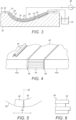
- the resin inlet channel 46 has a generally omega-shaped cross section, and extends longitudinally and substantially centrally in the mould. Resin is admitted into one end of the channel 46, for example the end 54 shown in cross-section in Figure 7 , and the resin flows along the channel 46 in a generally spanwise direction S. Resin also flows out of the channel 46 in a generally chordwise direction C across the foam panel 42 and spar cap 40 in the mould as represented by the arrows 56 in Figure 7 . The aim of this arrangement is to achieve an angled flow front of the resin across and along the components 40, 42 as represented schematically by the shaded region 58 in Figure 7 .
- the present invention provides a solution to this problem in the form of a method of making an elongate wind turbine blade according to claim 1.
- Steps b, c and d of the method of claim 1 may be performed in any order.
- resin-permeable material is provided between the spar structure and the core material.
- the resin-permeable material restricts the flow of resin in the spanwise direction at the interface between the spar structure and the core material as compared to the situation where resin-permeable material is not provided at these interfaces.
- the spar structure referred to above is a load-bearing structure and comprises a stack of pultruded strips of reinforcing material as described previously.
- the spar structure may be made of carbon-fibre reinforced plastic (CFRP).
- the core material may be any suitable core material, for example of the type typically used as the core of sandwich panels.
- the core material is foam, for example polyurethane foam, but it may instead be balsa or another suitably-lightweight material.
- the core material is in the form of panels that are arranged in abutment with the spar structure, as described earlier.
- the resin-permeable material may be any compliant material that is capable of reducing the flow rate of resin at the interface between the spar structure and the core material.
- the material is breather fabric, for example breather fabric made from polyester, nylon or blended fibreglass. Suitable breather fabrics include those produced by Tygavac Advanced Materials Ltd., such as the 'Econoweave', 'Airweave' and 'Ultraweave' series of fabrics.
- the breather fabric typically has a weight in the range of approximately 100 - 700 g/m 2 , although other weights may be suitable.
- the resin-permeable material may include polystyrene beads, spun polyester, or sponge material. The material will typically undergo some compression during the moulding process, and suitable materials are those that still allow resin to flow (albeit at a reduced flow rate) at the interface between the spar structure and the core material when the resin-permeable material is compressed to such an extent.
- the method may involve securing the resin-permeable material to the core material and/or to the spar structure. This has the advantageous effect of maintaining the breather fabric in the desired position during the layup process and during the subsequent infusion process.
- the resin-permeable material may be secured to the spar structure and/or to the core material when the associated component is arranged in the mould.
- the method may involve arranging the core material in the mould and subsequently attaching the resin-permeable to the core material, for example before the spar structures are arranged in the mould.
- a particularly advantageous effect may be realised by pre-attaching the resin-permeable material to the spar structure or to the core material before arranging the blade components in the mould.
- the resin-permeable material is pre-applied to the core material before the core material is arranged in the mould. This operation can be performed offline and hence reduces the blade production time in the mould.
- the resin-permeable material may be secured to the core material and/or to the spar structure by any suitable means, for example it may be bonded by a suitable adhesive or secured using scrim tape.
- the method may comprise administering resin into the mould in a direction transverse to the spanwise direction.
- the method comprises administering resin into the mould substantially in a chordwise direction, i.e. across the width of the mould.
- the method may further comprise providing a resin inlet channel extending longitudinally in the spanwise direction through which the resin is administered into the mould during the resin infusion process, and preferably the elongate spar structure is positioned between the resin-permeable material and the resin inlet channel. This prevents resin lock offs between the spar structure and the core material.
- the mould is preferably a blade shell mould.
- the mould may be a mould for making a half shell of a wind turbine blade.
- the mould may be configured to make an entire wind turbine blade.
- the mould may be for making a section of a wind turbine blade, for example in the case of a modular blade.
- the method may involve making only part of a wind turbine blade according to the present invention. For example, a mid-section of a blade may be made according to the above method, and the mid-section may subsequently be joined to a root and/or tip portion of the blade, or to another longitudinal section of the blade.
- a wind turbine blade may be made in accordance with the above method, and a wind turbine comprising the wind turbine blade.
- the wind turbine blade is formed by resin infusion according to the method described above.
- the resin-permeable material serves to restrict the rate of flow of resin between the spar structure and the core material in the spanwise direction.
- the resin-permeable material substantially fills any gaps at the interfaces between the spar structure and the core material and eliminates the race-track effect at such interfaces.
- FIG. 9 this is a cross section through a wind turbine blade shell mould 100.
- the mould 100 extends longitudinally in a spanwise direction perpendicular to the plane of the page.
- a surface 102 of the mould 100 exhibits a concave curvature in a chordwise direction C, corresponding to the curvature of the aerodynamic profile of the blade to be formed in the mould 100.
- the mould 100 is suitably-shaped for moulding a half shell of a wind turbine blade. In practice, two half shells may be moulded typically in separate moulds and the completed half shells are subsequently bonded together to form a complete blade, as will be readily apparent to persons skilled in the art.
- the present invention is not limited in this respect, and may instead be employed in other such moulding operations for example in which a complete blade is moulded in a single mould, or in which only a section of the blade is formed in the mould, such as in the case of a modular blade.
- one or more glass-fibre fabric layers 104 are arranged on the mould surface 102 to form the outer skin of the blade.
- a plurality of polyurethane foam panels 106a-c are then arranged on top of the glass-fibre layer(s). Three panels 106a-c are shown in the cross-sectional view of Figure 9 , although the number of panels may vary in other examples and/or at different spanwise locations in the mould 100, depending upon the structural requirements of the blade in such regions.
- the panels 106a-c are spaced apart from one another in the chordwise direction C such that a first spar region 108a is defined between a central panel 106b and a leading edge panel 106a and a second spar region 108b is defined between the central panel 106b and a trailing edge panel 106c.
- the spar regions 108a and 108b extend longitudinally in the spanwise direction of the mould 100.
- a plurality of pultruded strips 110 are stacked one on top of another in the first spar region 108a to form a first spar cap 112a.
- the pultrusions 110 are pre-cured strips of carbon-fibre reinforced plastic (CFRP).
- a second spar cap 112b is formed by stacking a further plurality of pre-cured CFRP pultrusions 110 in the second spar cap region 108b.
- breather fabric 114a-d is provided between the spar caps 112a and 112b and the foam panels 106a, 106b and 106c.
- the breather fabric 114 is in the form of longitudinal strips, which extend in the spanwise direction of the mould 100. In this example four strips of breather fabric 114a-d are arranged between the spar caps 112a and 112b and the adjacent foam panels 106a-c.
- a first strip 114a of breather fabric is provided between the first spar cap 112a and the leading edge panel 106a; a second strip 114b of breather fabric is provided between the first spar cap 112a and the central panel 106b; a third strip 114c of breather fabric is provided between the second spar cap 112b and the central panel 106b; and a fourth strip 114d of breather fabric is provided between the second spar cap 112b and the trailing edge panel 106c.
- the strips 114a-d of breather fabric are not necessarily a continuous length and may comprise a plurality of individual lengths of breather fabric arranged generally end to end in the spanwise direction, and/or overlapping to an extent.
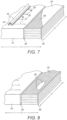
- FIG. 10 this is a schematic cross-sectional representation of the components once assembled in the mould.
- the foam panels 106a-c and spar caps 112a and 112b are arranged side by side and the breather fabric 114a-d is located between the foam panels 106a-c and the stacks of pultrusions 110 comprising the spar caps 112a and 112b.
- a resin inlet channel 116 is also shown in Figure 10 .
- the resin inlet channel 116 is identical to the resin-inlet channel 46 described above by way of background with reference to Figure 7 , and extends longitudinally and substantially centrally in the mould 100.
- the mould 100 and other blade components have been excluded from Figure 10 , and the foam panels 106a-c and spar caps 112a and 112b are shown in a flat formation whereas in reality the components would typically be arranged on the curved surface 102 of the mould 100, as shown in Figure 9 .
- one or more further layers of glass-fibre fabric 118 are arranged on top of the components to form the inner skin of the blade.
- the assembly is then covered with vacuum-bagging film 120, which is sealed against the mould flange 122 using sealing tape 124.
- a vacuum is created in the sealed region defined between the vacuum-bagging film 120 and the mould surface 102 and resin 126 is admitted into the sealed region via the resin inlet channel 116 shown in Figure 10 .
- the resin 126 flows out of the resin inlet channel 116 in a chordwise direction C through the mould 100, as represented by the arrows 56 in Figure 7 .
- Corresponding arrows 128 are shown in Figure 10 to indicate the direction of resin flow in the chordwise direction C in the present invention.
- the resin inlet channel 116 is arranged adjacent the central foam panel 106b, hence the resin initially flows across the central foam panel 106b.
- the resin reaches the respective interfaces 130b and 130c between the central panel 106b and the first and second spar caps 112a and 112b, the resin infuses into the breather fabric 114b and 114c at these locations.
- the resin then continues to flow in a chordwise direction C across the spar caps 112a and 112b until it reaches the respective interfaces 130a and 130d between the spar caps 112a and 112b and the respective leading edge and trailing edge panels 106a and 106c.
- the resin then infuses into the breather fabric 114a and 114d at these interfaces 130a and 130d before continuing to flow in a chordwise direction C across the respective leading and trailing edge panels 106a and 106c.
- the breather fabric 114a-d at the respective interfaces 130a-d between the spar caps 112a and 112b and the foam panels 106a-c occupies the gaps 48 that were described above by way of background to the present invention with reference to Figures 4 to 6 .
- the presence of the breather fabric 114a-d prevents the resin from racing in a spanwise direction at these interfaces 130a-d. Accordingly, the resin flows in a steady and controlled manner in the chordwise direction C across the foam panels 106a-c and the abutting spar caps 112a and 112b, such that lock-offs are substantially prevented.
- the breather fabric 114a-d may be secured to the foam panels 106a-c using glue, scrim tape or other suitable means.
- the above method may therefore involve arranging the foam panels 106a-c in the mould 100 and thereafter securing the breather fabric 114a-d to the foam panels 106a-c before stacking the pultrusions 110 in the spar regions 108a and 108b between the panels 106a-c.
- this shows an alternative example of the invention in which the breather fabric 114a-d is pre-applied to the sides of the foam panels 106a-c using scrim tape before the panels 106a-c are arranged in the mould 100.
- Pre-applying the breather fabric 114a-d to the foam panels 106a-c is particularly advantageous because this can be done offline, which can significantly reduce the time required to assemble the various components in the mould 100, and thereby reducing the blade production time.
- 'spanwise' and 'chordwise' are used herein for convenience and should not be interpreted in such a way as to unduly limit the scope of the present invention.
- 'Spanwise' is intended to mean a longitudinal direction, generally between the root and tip of a wind turbine blade or blade mould, and is not necessarily intended to mean directions parallel to the blade axis.
- 'Chordwise' is intended to mean a widthwise direction across the blade or mould, and is not necessarily intended to mean parallel to the blade chord.
Landscapes
- Engineering & Computer Science (AREA)
- Mechanical Engineering (AREA)
- Chemical & Material Sciences (AREA)
- Composite Materials (AREA)
- Life Sciences & Earth Sciences (AREA)
- Sustainable Development (AREA)
- Sustainable Energy (AREA)
- Combustion & Propulsion (AREA)
- General Engineering & Computer Science (AREA)
- Wind Motors (AREA)
Description
- The present invention relates to an improved method of making a wind turbine blade.
-
EP2444660 describes a wind turbine blade having a spar cap which is formed as a separate piece to the rest of the blade.WO2013/178228 describes a method of smoothing a transition between discontinuous surfaces in a wind turbine blade, in particular between a spar cap and a sandwich panel. -
Figure 1 is a cross-sectional view of a windturbine rotor blade 10. The blade has an outer shell, which is fabricated from two half shells: awindward shell 11a and aleeward shell 11b. Theshells outer shell 11 are of sandwich panel construction and comprise acore 12 of lightweight material such as foam (e.g. polyurethane) or balsa, which is sandwiched between inner 13 and outer 14 GRP layers or 'skins'. Other core materials will be apparent to persons skilled in the art. - The
blade 10 comprises a first pair of load-bearing structures in the form ofspar caps spar caps spar caps shells spar cap windward shell 11a and theother spar cap leeward shell 11b. The spar caps of the respective pairs are mutually opposed and extend longitudinally along the length of theblade 10. - A first longitudinally-extending
shear web 17a bridges the first pair ofspar caps shear web 17b bridges the second pair ofspar caps shear webs spar caps blade 10 to the hub of the wind turbine. Thespar caps shear webs blade 10. - Each
spar cap pre-fabricated reinforcing strips 18. Thestrips 18 are pre-cured pultruded strips of carbon-fibre reinforced plastic (CFRP), and are substantially flat and of rectangular cross section. The number ofstrips 18 in the stack depends upon the thickness of thestrips 18 and the required thickness of theshells strips 18 each have a thickness of a few millimetres and there may be between three and twelve strips in a stack. Thestrips 18 have a high tensile strength, and hence have a high load bearing capacity. - The
blade 10 is made using a resin-infusion process as will now be described by way of example with reference toFigures 2 and3 . Referring toFigure 2 , this shows amould 20 for a half shell of a wind turbine blade in cross-section. A glass-fibre layer 22 is arranged in themould 20 to form theouter skin 14 of theblade 10. Threeelongate panels 24 of polyurethane foam are arranged on top of the glass-fibre layer 22 to form thesandwich panel cores 12 referred to above. Thefoam panels 24 are spaced apart relative to one another to define a pair ofchannels 26 in between. A plurality ofpultruded strips 18 of CFRP, as described above with reference toFigure 1 , are stacked in therespective channels 26. Threestrips 18 are shown in each stack in this example, but there may be any number ofstrips 18 in a stack. - Referring to
Figure 3 , once thestrips 18 have been stacked, a second glass-fibre layer 28 is arranged on top of thefoam panels 24 and the stacks ofpultruded strips 18. The second glass-fibre layer 28 forms theinner skin 13 of theblade 10. Next,vacuum bagging film 30 is placed over themould 20 to cover the layup.Sealing tape 32 is used to seal thevacuum bagging film 30 to aflange 34 of themould 20. Avacuum pump 36 is used to withdraw air from the sealed region between themould 20 and thevacuum bagging film 30, andresin 38 is supplied to the sealed region. Theresin 38 infuses between the various laminate layers and fills any gaps in the laminate layup. Oncesufficient resin 38 has been supplied to themould 20, themould 20 is heated whilst the vacuum is maintained to cure theresin 38 and bond the various layers together to form the half shell of the blade. The other half shell is made according to an identical process. Adhesive is then applied along the leading and trailing edges of the shells and the shells are bonded together to form the complete blade. - The integration of the
spar caps outer shells EP 1 520 983WO 2006/082479 andUK Patent Application GB 2497578 EP 2 444 660 describes a wind turbine blade having a spar cap as a main structural member disposed between an inner skin and an outer skin. - When manufacturing wind turbine blades using a resin infusion process, it is important to control the resin flow front during the infusion process to ensure that the resin infuses evenly and completely throughout the laminate layup and between all of the shell components. If the flow front is not carefully controlled, then air pockets (also referred to as 'lock offs' or voids) may develop in the blade structure. Air pockets are caused by the incomplete infusion of resin in certain regions of the blade, and can result in localised weaknesses in the blade structure.
- The present invention has been developed against this background, and provides an improved method of manufacturing a wind turbine blade. In particular, the invention provides increased control over the resin flow front during resin infusion and eliminates or at least significantly reduces the possibility of air pockets forming. The present invention resides both in the identification of the problem, and in the solution to the problem.
- The particular problem identified by the inventors will now be described in detail with reference to
Figures 4 to 8 . -
Figure 4 is a schematic representation of aspar structure 40 for a wind turbine blade arranged between first andsecond foam panels Figure 4 , thespar structure 40 in this example is a spar cap and comprises a plurality ofCFRP pultrusions 44 arranged one on top of another to form a stack. Thefoam panels spar cap 40 andfoam panels Figure 2 . Both thespar structure 40 and thefoam panels resin inlet channel 46 is also shown inFigure 4 , and will be described in further detail later with reference toFigure 7 . - As shown in
Figure 4 , asmall gap 48 is present on each side of thespar cap 40, between thespar cap 40 and theadjacent foam panel spar caps 40 andfoam panels small gap 48 is inevitable for reasons as will now be explained with reference toFigures 5 and 6 . -
Figure 5 is a schematic representation of a transverse cross section taken through a wind turbineblade shell mould 50. Aspar cap 40 andadjacent foam panel 42 are also shown schematically inside themould 50. Theblade shell mould 50 has a concave curvature generally in the chordwise direction C, corresponding to part of the airfoil profile of the blade to be produced. The curvature of themould 50 prevents thespar cap 40 andfoam panel 42 from abutting closely across theentire interface 52 between the twocomponents gap 48 at theinterface 52. - Referring now also to
Figure 6 , this is a schematic representation of part of thespar cap 40. Here it can be seen that there may be a slight misalignment between thestacked pultrusions 44 comprising thespar cap 40. The misalignments are exaggerated for clarity inFigure 6 , and in practice any misalignment may only be a fraction of a millimetre. In any event, misalignment between thestacked pultrusions 44 results in the longitudinal sides of thespar cap 40 not being perfectly flat, and this also contributes to the longitudinally-extendinggaps 48 between thespar cap 40 and theadjacent foam panel 42 at theinterface 52 between theabutting components - The
gaps 48 described above may cause undesirable resin flow during the infusion process as will now be described with reference toFigures 7 and 8 . - Referring to
Figure 7 , during the resin infusion process, resin is admitted into the mould via theresin inlet channel 46. Theresin inlet channel 46 has a generally omega-shaped cross section, and extends longitudinally and substantially centrally in the mould. Resin is admitted into one end of thechannel 46, for example theend 54 shown in cross-section inFigure 7 , and the resin flows along thechannel 46 in a generally spanwise direction S. Resin also flows out of thechannel 46 in a generally chordwise direction C across thefoam panel 42 andspar cap 40 in the mould as represented by thearrows 56 inFigure 7 . The aim of this arrangement is to achieve an angled flow front of the resin across and along thecomponents region 58 inFigure 7 . - However, and referring now to
Figure 8 , when the resin reaches the longitudinally-extendinggaps 48 between thespar cap 40 and thefoam panels 42, thegaps 48 act as `race tracks' for the resin, and the resin flows quickly along thegaps 48 in the spanwise direction S. The fast and uncontrolled resin flow along thegaps 48 can result inresin lock offs 60 forming, as shown inFigure 8 . The air contained in the lock off 60 cannot escape and so this region will not be infused. This lock off 60 may be present betweenindividual pultrusions 44 of thespar cap 40. - The present invention provides a solution to this problem in the form of a method of making an elongate wind turbine blade according to
claim 1. - Steps b, c and d of the method of
claim 1 may be performed in any order. - According to the present invention, resin-permeable material is provided between the spar structure and the core material. The resin-permeable material restricts the flow of resin in the spanwise direction at the interface between the spar structure and the core material as compared to the situation where resin-permeable material is not provided at these interfaces. Thus, the race track effect described above, and the associated resin lock offs, are effectively prevented, and a more controlled resin flow front is achieved in the chordwise direction.
- The spar structure referred to above is a load-bearing structure and comprises a stack of pultruded strips of reinforcing material as described previously. For example the spar structure may be made of carbon-fibre reinforced plastic (CFRP).
- The core material may be any suitable core material, for example of the type typically used as the core of sandwich panels. Preferably the core material is foam, for example polyurethane foam, but it may instead be balsa or another suitably-lightweight material. In preferred examples of the invention, the core material is in the form of panels that are arranged in abutment with the spar structure, as described earlier.
- The resin-permeable material may be any compliant material that is capable of reducing the flow rate of resin at the interface between the spar structure and the core material. In preferred embodiments of the invention, the material is breather fabric, for example breather fabric made from polyester, nylon or blended fibreglass. Suitable breather fabrics include those produced by Tygavac Advanced Materials Ltd., such as the 'Econoweave', 'Airweave' and 'Ultraweave' series of fabrics. The breather fabric typically has a weight in the range of approximately 100 - 700 g/m2, although other weights may be suitable. As an alternative to breather fabric, the resin-permeable material may include polystyrene beads, spun polyester, or sponge material. The material will typically undergo some compression during the moulding process, and suitable materials are those that still allow resin to flow (albeit at a reduced flow rate) at the interface between the spar structure and the core material when the resin-permeable material is compressed to such an extent.
- The method may involve securing the resin-permeable material to the core material and/or to the spar structure. This has the advantageous effect of maintaining the breather fabric in the desired position during the layup process and during the subsequent infusion process. The resin-permeable material may be secured to the spar structure and/or to the core material when the associated component is arranged in the mould. For example the method may involve arranging the core material in the mould and subsequently attaching the resin-permeable to the core material, for example before the spar structures are arranged in the mould.
- A particularly advantageous effect may be realised by pre-attaching the resin-permeable material to the spar structure or to the core material before arranging the blade components in the mould. For example in a particular example of the invention, the resin-permeable material is pre-applied to the core material before the core material is arranged in the mould. This operation can be performed offline and hence reduces the blade production time in the mould. The resin-permeable material may be secured to the core material and/or to the spar structure by any suitable means, for example it may be bonded by a suitable adhesive or secured using scrim tape.
- During the resin-infusion process, the method may comprise administering resin into the mould in a direction transverse to the spanwise direction. Preferably the method comprises administering resin into the mould substantially in a chordwise direction, i.e. across the width of the mould.
- The method may further comprise providing a resin inlet channel extending longitudinally in the spanwise direction through which the resin is administered into the mould during the resin infusion process, and preferably the elongate spar structure is positioned between the resin-permeable material and the resin inlet channel. This prevents resin lock offs between the spar structure and the core material.
- The mould is preferably a blade shell mould. The mould may be a mould for making a half shell of a wind turbine blade. Alternatively the mould may be configured to make an entire wind turbine blade. As a further alternative, the mould may be for making a section of a wind turbine blade, for example in the case of a modular blade. Hence, the method may involve making only part of a wind turbine blade according to the present invention. For example, a mid-section of a blade may be made according to the above method, and the mid-section may subsequently be joined to a root and/or tip portion of the blade, or to another longitudinal section of the blade.
- A wind turbine blade may be made in accordance with the above method, and a wind turbine comprising the wind turbine blade.
- The wind turbine blade is formed by resin infusion according to the method described above. During the resin-infusion process, the resin-permeable material serves to restrict the rate of flow of resin between the spar structure and the core material in the spanwise direction. The resin-permeable material substantially fills any gaps at the interfaces between the spar structure and the core material and eliminates the race-track effect at such interfaces.
- The background to the present invention has already been described above with reference to
Figures 1 to 3 in which: -
Figure 1 is a schematic transverse cross-sectional view through a wind turbine blade having a fibre-reinforced shell of sandwich panel construction and having spar structures integrated with the shell and located between regions of core material; -
Figure 2 is a schematic transverse cross-section through a wind turbine blade shell mould for making the blade shown inFigure 1 , and illustrating the core material and spar structure being arranged in the mould; and -
Figure 3 illustrates a resin-infusion process for making the wind turbine blade ofFigure 1 . - A particular problem addressed by the method of the present invention has also been described above with reference to
Figures 4 to 8 , in which: -
Figure 4 schematically illustrates longitudinal gaps at the interfaces between a spar structure and panels of core material when these components are arranged in a wind turbine blade mould; -
Figure 5 schematically illustrates how the curvature of a wind turbine blade mould causes a gap between abutting spar structures and core panels; -
Figure 6 is a schematic illustration of part of a spar structure comprising a stack of pultrusions and showing slight misalignments between the pultrusions; -
Figure 7 illustrates resin flow during a resin-infusion process, in which resin flows in a chordwise direction across the core panel and spar structure; and -
Figure 8 illustrates a lock off created by uncontrolled resin flow in a spanwise direction at the interface between the core panel and the spar structure. - In order that the present invention may be more readily understood, a method of making a wind turbine blade in accordance with particular embodiments of the present invention will now be described in further detail with reference to the following figures, in which:
-
Figure 9 is a schematic transverse cross-section through a wind turbine blade shell mould, and shows resin-permeable material being arranged in the mould between spar structures and panels of core material; -
Figure 10 is a schematic representation of a pair of spar structures arranged between panels of core material with resin-permeable material provided at the interfaces between the core panels and spar structures; -
Figure 11 illustrates a resin-infusion process for making a wind turbine blade according to the present invention; and -
Figure 12 illustrates a further embodiment of the present invention in which resin-permeable material is pre-applied to core panels before the core panels are placed in the mould. - Referring now to
Figure 9 , this is a cross section through a wind turbineblade shell mould 100. Themould 100 extends longitudinally in a spanwise direction perpendicular to the plane of the page. Asurface 102 of themould 100 exhibits a concave curvature in a chordwise direction C, corresponding to the curvature of the aerodynamic profile of the blade to be formed in themould 100. Themould 100 is suitably-shaped for moulding a half shell of a wind turbine blade. In practice, two half shells may be moulded typically in separate moulds and the completed half shells are subsequently bonded together to form a complete blade, as will be readily apparent to persons skilled in the art. However, it should be appreciated that the present invention is not limited in this respect, and may instead be employed in other such moulding operations for example in which a complete blade is moulded in a single mould, or in which only a section of the blade is formed in the mould, such as in the case of a modular blade. - In order to form the blade half shell in the
mould 100, one or more glass-fibre fabric layers 104 are arranged on themould surface 102 to form the outer skin of the blade. A plurality ofpolyurethane foam panels 106a-c are then arranged on top of the glass-fibre layer(s). Threepanels 106a-c are shown in the cross-sectional view ofFigure 9 , although the number of panels may vary in other examples and/or at different spanwise locations in themould 100, depending upon the structural requirements of the blade in such regions. Thepanels 106a-c are spaced apart from one another in the chordwise direction C such that afirst spar region 108a is defined between acentral panel 106b and aleading edge panel 106a and asecond spar region 108b is defined between thecentral panel 106b and a trailingedge panel 106c. Thespar regions mould 100. - A plurality of
pultruded strips 110 are stacked one on top of another in thefirst spar region 108a to form afirst spar cap 112a. Thepultrusions 110 are pre-cured strips of carbon-fibre reinforced plastic (CFRP). Asecond spar cap 112b is formed by stacking a further plurality of pre-cured CFRP pultrusions 110 in the secondspar cap region 108b. - In accordance with the present invention,
breather fabric 114a-d is provided between the spar caps 112a and 112b and thefoam panels mould 100. In this example four strips ofbreather fabric 114a-d are arranged between the spar caps 112a and 112b and theadjacent foam panels 106a-c. Specifically, afirst strip 114a of breather fabric is provided between thefirst spar cap 112a and theleading edge panel 106a; asecond strip 114b of breather fabric is provided between thefirst spar cap 112a and thecentral panel 106b; athird strip 114c of breather fabric is provided between thesecond spar cap 112b and thecentral panel 106b; and afourth strip 114d of breather fabric is provided between thesecond spar cap 112b and the trailingedge panel 106c. Thestrips 114a-d of breather fabric are not necessarily a continuous length and may comprise a plurality of individual lengths of breather fabric arranged generally end to end in the spanwise direction, and/or overlapping to an extent. - Referring now to
Figure 10 , this is a schematic cross-sectional representation of the components once assembled in the mould. Here it can be seen that thefoam panels 106a-c and sparcaps breather fabric 114a-d is located between thefoam panels 106a-c and the stacks ofpultrusions 110 comprising the spar caps 112a and 112b. Aresin inlet channel 116 is also shown inFigure 10 . Theresin inlet channel 116 is identical to the resin-inlet channel 46 described above by way of background with reference toFigure 7 , and extends longitudinally and substantially centrally in themould 100. For ease of illustration, themould 100 and other blade components have been excluded fromFigure 10 , and thefoam panels 106a-c and sparcaps curved surface 102 of themould 100, as shown inFigure 9 . - Referring now to
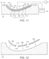
Figure 11 , once the components have been arranged in themould 100, one or more further layers of glass-fibre fabric 118 are arranged on top of the components to form the inner skin of the blade. The assembly is then covered with vacuum-baggingfilm 120, which is sealed against themould flange 122 using sealingtape 124. A vacuum is created in the sealed region defined between the vacuum-baggingfilm 120 and themould surface 102 andresin 126 is admitted into the sealed region via theresin inlet channel 116 shown inFigure 10 . - As described by way of background with reference to
Figure 7 , theresin 126 flows out of theresin inlet channel 116 in a chordwise direction C through themould 100, as represented by thearrows 56 inFigure 7 . Correspondingarrows 128 are shown inFigure 10 to indicate the direction of resin flow in the chordwise direction C in the present invention. Referring again toFigure 10 , theresin inlet channel 116 is arranged adjacent thecentral foam panel 106b, hence the resin initially flows across thecentral foam panel 106b. When the resin reaches therespective interfaces central panel 106b and the first andsecond spar caps breather fabric respective interfaces edge panels breather fabric interfaces edge panels - The
breather fabric 114a-d at therespective interfaces 130a-d between the spar caps 112a and 112b and thefoam panels 106a-c occupies thegaps 48 that were described above by way of background to the present invention with reference toFigures 4 to 6 . The presence of thebreather fabric 114a-d prevents the resin from racing in a spanwise direction at theseinterfaces 130a-d. Accordingly, the resin flows in a steady and controlled manner in the chordwise direction C across thefoam panels 106a-c and the abuttingspar caps - In order to maintain the
breather fabric 114a-d in position during the layup process and during the moulding process, thebreather fabric 114a-d may be secured to thefoam panels 106a-c using glue, scrim tape or other suitable means. The above method may therefore involve arranging thefoam panels 106a-c in themould 100 and thereafter securing thebreather fabric 114a-d to thefoam panels 106a-c before stacking thepultrusions 110 in thespar regions panels 106a-c. - Referring now to
Figure 12 , this shows an alternative example of the invention in which thebreather fabric 114a-d is pre-applied to the sides of thefoam panels 106a-c using scrim tape before thepanels 106a-c are arranged in themould 100. Pre-applying thebreather fabric 114a-d to thefoam panels 106a-c is particularly advantageous because this can be done offline, which can significantly reduce the time required to assemble the various components in themould 100, and thereby reducing the blade production time. - In
Figures 9 to 12 , fours strips ofbreather fabric 114a-d have been provided at the interface between the foam panels and the spar caps. However, in an example, only strips 114a and 114d may be provided. The spar caps 112a and 112b are located between the twostrips resin inlet channel 116. By providing the strips of breather fabric in these locations eliminates the race track effect at the respective interfaces between thefoam panels - For the avoidance of doubt, the terms 'spanwise' and 'chordwise' are used herein for convenience and should not be interpreted in such a way as to unduly limit the scope of the present invention. 'Spanwise' is intended to mean a longitudinal direction, generally between the root and tip of a wind turbine blade or blade mould, and is not necessarily intended to mean directions parallel to the blade axis. 'Chordwise' is intended to mean a widthwise direction across the blade or mould, and is not necessarily intended to mean parallel to the blade chord.
- Many modifications may be made to the above examples without departing from the scope of the present invention as defined in the accompanying claims.
Claims (12)
- A method of making an elongate wind turbine blade extending longitudinally between a root end and a tip end in a spanwise direction, the method comprising:a. providing an elongate blade shell mould tool (100) extending longitudinally in a spanwise direction, the mould comprising a concave curvature in a chordwise direction, corresponding to the curvature of the aerodynamic profile of the blade to be formed in the mould;b. arranging an elongate spar structure (112a) in the mould tool (100), the spar structure comprising a stack of pultruded strips of reinforcing material, and the spar structure extending longitudinally in the spanwise direction;c. arranging core material (106a) adjacent to the spar structure (112a);d. providing resin-permeable material (114a) at an interface between the spar structure (112a) and the core material (106a); ande. administering resin (126) into the mould (100) during a resin infusion process, wherein the resin-permeable material (114a) restricts the flow of resin between the spar structure (112a) and the core material (106a) in the spanwise direction.
- The method of Claim 1 wherein the resin-permeable material (114a) is breather fabric.
- The method of Claim 1 or Claim 2, further comprising securing the resin-permeable material to the core material and/or to the spar structure.
- The method of Claim 1, further comprising securing the resin-permeable material (114a) to the spar structure (112a) and/or to the core material (106a) prior to arranging the blade components in the mould (100).
- The method of any preceding claim, further comprising bonding the resin-permeable material (114a) to the core material (106a) prior to arranging the core material in the mould (100).
- The method of any preceding claim, wherein step (e) comprises administering resin (126) into the mould (100) in a direction transverse to the spanwise direction.
- The method of Claim 6, wherein step (e) comprises administering resin (126) into the mould (100) substantially in a chordwise direction.
- The method of any preceding claim, further comprising providing a resin inlet channel (116) extending longitudinally in the spanwise direction through which the resin is administered into the mould (100) during the resin infusion process, wherein the elongate spar structure (112a) is positioned between the resin-permeable material (114a) and the resin inlet channel (116).
- The method of any preceding claim, wherein the spar structure (112a) is a pre-cured component.
- The method of any preceding claim, wherein the spar structure (112a) is made from carbon fibre reinforced plastic.
- The method of any preceding claim, wherein the core material (106a) is foam or balsa.
- The method of any preceding claim, wherein the core material (106a) comprises one or more panels.
Applications Claiming Priority (2)
| Application Number | Priority Date | Filing Date | Title |
|---|---|---|---|
| DKPA201370816 | 2013-12-23 | ||
| PCT/DK2014/050432 WO2015096840A1 (en) | 2013-12-23 | 2014-12-15 | Wind turbine blades |
Publications (3)
| Publication Number | Publication Date |
|---|---|
| EP3086924A1 EP3086924A1 (en) | 2016-11-02 |
| EP3086924C0 EP3086924C0 (en) | 2024-10-23 |
| EP3086924B1 true EP3086924B1 (en) | 2024-10-23 |
Family
ID=52231784
Family Applications (1)
| Application Number | Title | Priority Date | Filing Date |
|---|---|---|---|
| EP14820739.2A Active EP3086924B1 (en) | 2013-12-23 | 2014-12-15 | Wind turbine blades |
Country Status (5)
| Country | Link |
|---|---|
| US (1) | US10428790B2 (en) |
| EP (1) | EP3086924B1 (en) |
| CN (1) | CN106029347B (en) |
| ES (1) | ES2990977T3 (en) |
| WO (1) | WO2015096840A1 (en) |
Families Citing this family (39)
| Publication number | Priority date | Publication date | Assignee | Title |
|---|---|---|---|---|
| US9869296B2 (en) * | 2015-05-07 | 2018-01-16 | General Electric Company | Attachment method and system to install components, such as tip extensions and winglets, to a wind turbine blade |
| US9869295B2 (en) * | 2015-05-07 | 2018-01-16 | General Electric Company | Attachment method to install components, such as tip extensions and winglets, to a wind turbine blade, as well as the wind turbine blade and component |
| EP3303830B1 (en) * | 2015-05-28 | 2022-09-14 | LM Wind Power A/S | Wind turbine blade with a trailing edge spacing section |
| DK3393767T3 (en) * | 2015-12-23 | 2024-05-21 | Lm Wind Power As | A method of manufacturing a composite laminate structure of a wind turbine blade part and related wind turbine blade part |
| CA3015015A1 (en) * | 2016-02-23 | 2017-08-31 | Lm Wp Patent Holding A/S | Method of manufacturing a composite laminate structure |
| CN109641408A (en) * | 2016-06-28 | 2019-04-16 | 维斯塔斯风力系统有限公司 | Manufacturing method of wind turbine blade |
| US11572861B2 (en) * | 2017-01-31 | 2023-02-07 | General Electric Company | Method for forming a rotor blade for a wind turbine |
| US10830206B2 (en) | 2017-02-03 | 2020-11-10 | General Electric Company | Methods for manufacturing wind turbine rotor blades and components thereof |
| US11098691B2 (en) | 2017-02-03 | 2021-08-24 | General Electric Company | Methods for manufacturing wind turbine rotor blades and components thereof |
| US10619622B2 (en) * | 2017-06-21 | 2020-04-14 | General Electric Company | Wind turbine blade with hybrid spar cap and associated method for making |
| CN111405975A (en) * | 2017-06-30 | 2020-07-10 | 泰普爱复合材料股份有限公司 | Optimizing a layup process for the manufacture of wind turbine blades using a model-based optical projection system |
| EP3427931B1 (en) * | 2017-07-13 | 2020-03-11 | LM Wind Power International Technology II ApS | A wind turbine blade and a method of manufacturing the wind turbine blade |
| US10677216B2 (en) | 2017-10-24 | 2020-06-09 | General Electric Company | Wind turbine rotor blade components formed using pultruded rods |
| US11248582B2 (en) | 2017-11-21 | 2022-02-15 | General Electric Company | Multiple material combinations for printed reinforcement structures of rotor blades |
| US11040503B2 (en) | 2017-11-21 | 2021-06-22 | General Electric Company | Apparatus for manufacturing composite airfoils |
| US10913216B2 (en) | 2017-11-21 | 2021-02-09 | General Electric Company | Methods for manufacturing wind turbine rotor blade panels having printed grid structures |
| US10920745B2 (en) | 2017-11-21 | 2021-02-16 | General Electric Company | Wind turbine rotor blade components and methods of manufacturing the same |
| US10773464B2 (en) | 2017-11-21 | 2020-09-15 | General Electric Company | Method for manufacturing composite airfoils |
| US11668275B2 (en) | 2017-11-21 | 2023-06-06 | General Electric Company | Methods for manufacturing an outer skin of a rotor blade |
| US11390013B2 (en) | 2017-11-21 | 2022-07-19 | General Electric Company | Vacuum forming mold assembly and associated methods |
| US10821652B2 (en) | 2017-11-21 | 2020-11-03 | General Electric Company | Vacuum forming mold assembly and method for creating a vacuum forming mold assembly |
| US10865769B2 (en) | 2017-11-21 | 2020-12-15 | General Electric Company | Methods for manufacturing wind turbine rotor blade panels having printed grid structures |
| PT3501809T (en) | 2017-12-22 | 2025-01-24 | Siemens Gamesa Renewable Energy As | Pultruded fibrous composite strips having non-planar profiles cross-section for wind turbine blade spar caps |
| US11738530B2 (en) | 2018-03-22 | 2023-08-29 | General Electric Company | Methods for manufacturing wind turbine rotor blade components |
| US11035339B2 (en) * | 2018-03-26 | 2021-06-15 | General Electric Company | Shear web assembly interconnected with additive manufactured components |
| US10821696B2 (en) | 2018-03-26 | 2020-11-03 | General Electric Company | Methods for manufacturing flatback airfoils for wind turbine rotor blades |
| CN108501407B (en) * | 2018-04-04 | 2020-01-10 | 中材科技(阜宁)风电叶片有限公司 | Anti-deformation installation method for prefabricated part of blade root of large wind power blade |
| ES2955532T3 (en) | 2018-06-11 | 2023-12-04 | Vestas Wind Sys As | Wind turbine blade spar structure and manufacturing method |
| ES2974093T3 (en) * | 2018-07-23 | 2024-06-25 | Siemens Gamesa Renewable Energy As | Wind turbine blade comprising a composite material and a method for producing a wind turbine blade |
| DK180532B1 (en) | 2019-04-23 | 2021-06-10 | Envision Energy Denmark Aps | A WIND WINDOW WING AND A METHOD FOR MANUFACTURING THE WIND WIND WING |
| CN110894818B (en) * | 2019-12-20 | 2023-11-17 | 中材科技风电叶片股份有限公司 | Blade shell, manufacturing method and blade |
| PL4019233T3 (en) | 2020-12-22 | 2025-06-02 | Siemens Gamesa Renewable Energy A/S | Method of manufacturing an adaptable carbon-fibre beam |
| WO2022136256A1 (en) * | 2020-12-22 | 2022-06-30 | Lm Wind Power A/S | A method of manufacturing a shell of a wind turbine blade |
| CN113119495A (en) * | 2021-04-02 | 2021-07-16 | 中材科技风电叶片股份有限公司 | Blade shell preparation method and blade |
| US11988191B2 (en) * | 2021-12-15 | 2024-05-21 | Alliance For Sustainable Energy, Llc | Inflatable wind turbine blade and attachment mechanism |
| CN114311754A (en) * | 2021-12-31 | 2022-04-12 | 江苏金风科技有限公司 | Method for manufacturing blade member and blade |
| EP4212324B1 (en) * | 2022-01-17 | 2024-07-17 | LM Wind Power A/S | Manufacturing of wind turbine blade spar cap |
| GB2619916B (en) * | 2022-06-14 | 2025-05-21 | Anemoi Marine Tech Limited | A sail body for forming part of a wind assisted propulsion device |
| CN115122671B (en) * | 2022-06-24 | 2024-06-28 | 灵均先进材料(苏州)有限公司 | Large-scale component vacuum infusion production process based on epoxy resin |
Citations (10)
| Publication number | Priority date | Publication date | Assignee | Title |
|---|---|---|---|---|
| WO2006058540A1 (en) | 2004-11-30 | 2006-06-08 | Lm Glasfiber A/S | Vacuum infusion by means of a semi-permeable membrane |
| WO2006082479A1 (en) | 2005-02-03 | 2006-08-10 | Vestas Wind Systems A/S | Method of manufacturing a wind turbine blade shell member |
| US20110135485A1 (en) | 2009-12-30 | 2011-06-09 | Jing Wang | Spar for a wind turbine rotor blade and method for fabricating the same |
| EP2404743A1 (en) | 2010-07-09 | 2012-01-11 | Lm Glasfiber A/S | Method of producing pre-bent wind turbine blades |
| EP2444660A1 (en) | 2009-07-09 | 2012-04-25 | Mitsubishi Heavy Industries, Ltd. | Wind turbine blade and method of manufacturing same |
| US20120251811A1 (en) | 2007-06-29 | 2012-10-04 | Lm Glasfiber A/S | Method for producing a composite structure and a composite structure |
| US20120321480A1 (en) | 2011-06-17 | 2012-12-20 | Lm Wind Power A/S | Method of manufacturing an oblong shell part and such shell part |
| US8402652B2 (en) | 2005-10-28 | 2013-03-26 | General Electric Company | Methods of making wind turbine rotor blades |
| WO2013087078A1 (en) | 2011-12-16 | 2013-06-20 | Vestas Wind Systems A/S | Wind turbine blades |
| WO2013178228A1 (en) * | 2012-05-31 | 2013-12-05 | Vestas Wind Systems A/S | Manufacture of wind turbine blades |
Family Cites Families (7)
| Publication number | Priority date | Publication date | Assignee | Title |
|---|---|---|---|---|
| WO2003008800A1 (en) | 2001-07-19 | 2003-01-30 | Neg Micon A/S | Wind turbine blade |
| US20050136761A1 (en) * | 2003-12-17 | 2005-06-23 | Daikin Industries, Ltd. | Fire-Retardant Composite Material |
| US7517198B2 (en) * | 2006-03-20 | 2009-04-14 | Modular Wind Energy, Inc. | Lightweight composite truss wind turbine blade |
| DE102008045601A1 (en) * | 2008-06-27 | 2009-12-31 | Repower Systems Ag | Rotor blade for a wind energy plant and method and production form for its production |
| DE102009048000A1 (en) * | 2009-10-01 | 2011-09-15 | Bayer Materialscience Ag | Composite made of open-cell rigid foam |
| US8192169B2 (en) * | 2010-04-09 | 2012-06-05 | Frederick W Piasecki | Highly reliable, low cost wind turbine rotor blade |
| US7976275B2 (en) * | 2010-08-30 | 2011-07-12 | General Electric Company | Wind turbine rotor blade assembly having an access window and related methods |
-
2014
- 2014-12-15 EP EP14820739.2A patent/EP3086924B1/en active Active
- 2014-12-15 ES ES14820739T patent/ES2990977T3/en active Active
- 2014-12-15 WO PCT/DK2014/050432 patent/WO2015096840A1/en not_active Ceased
- 2014-12-15 US US15/107,386 patent/US10428790B2/en active Active
- 2014-12-15 CN CN201480076101.5A patent/CN106029347B/en active Active
Patent Citations (11)
| Publication number | Priority date | Publication date | Assignee | Title |
|---|---|---|---|---|
| WO2006058540A1 (en) | 2004-11-30 | 2006-06-08 | Lm Glasfiber A/S | Vacuum infusion by means of a semi-permeable membrane |
| WO2006082479A1 (en) | 2005-02-03 | 2006-08-10 | Vestas Wind Systems A/S | Method of manufacturing a wind turbine blade shell member |
| EP1846657B1 (en) * | 2005-02-03 | 2013-08-21 | Vestas Wind Systems A/S | Method of manufacturing a wind turbine blade shell member |
| US8402652B2 (en) | 2005-10-28 | 2013-03-26 | General Electric Company | Methods of making wind turbine rotor blades |
| US20120251811A1 (en) | 2007-06-29 | 2012-10-04 | Lm Glasfiber A/S | Method for producing a composite structure and a composite structure |
| EP2444660A1 (en) | 2009-07-09 | 2012-04-25 | Mitsubishi Heavy Industries, Ltd. | Wind turbine blade and method of manufacturing same |
| US20110135485A1 (en) | 2009-12-30 | 2011-06-09 | Jing Wang | Spar for a wind turbine rotor blade and method for fabricating the same |
| EP2404743A1 (en) | 2010-07-09 | 2012-01-11 | Lm Glasfiber A/S | Method of producing pre-bent wind turbine blades |
| US20120321480A1 (en) | 2011-06-17 | 2012-12-20 | Lm Wind Power A/S | Method of manufacturing an oblong shell part and such shell part |
| WO2013087078A1 (en) | 2011-12-16 | 2013-06-20 | Vestas Wind Systems A/S | Wind turbine blades |
| WO2013178228A1 (en) * | 2012-05-31 | 2013-12-05 | Vestas Wind Systems A/S | Manufacture of wind turbine blades |
Also Published As
| Publication number | Publication date |
|---|---|
| CN106029347B (en) | 2018-04-17 |
| EP3086924C0 (en) | 2024-10-23 |
| ES2990977T3 (en) | 2024-12-02 |
| US10428790B2 (en) | 2019-10-01 |
| US20160319801A1 (en) | 2016-11-03 |
| WO2015096840A1 (en) | 2015-07-02 |
| CN106029347A (en) | 2016-10-12 |
| EP3086924A1 (en) | 2016-11-02 |
Similar Documents
| Publication | Publication Date | Title |
|---|---|---|
| EP3086924B1 (en) | Wind turbine blades | |
| EP2778393A2 (en) | Wind turbine blade design and associated manufacturing methods using rectangular spars | |
| EP2358998B1 (en) | Efficient wind turbine blades, wind turbine blade structures, and associated systems and methods of manufacture, assembly and use | |
| EP3212387B1 (en) | Manufacture of i-shaped shear web, method and apparatus | |
| US20210324830A1 (en) | Modular wind turbine blades | |
| EP2922690B1 (en) | Wind turbine blades and method of manufacturing the same | |
| EP2109713B1 (en) | Wind turbine blade | |
| EP3418557B1 (en) | A wind turbine blade with hybrid spar cap and associated method for making | |
| EP3380313B1 (en) | Improvements relating to the manufacture of wind turbine blades | |
| EP3651975B1 (en) | A wind turbine blade and a method of manufacturing the wind turbine blade | |
| EP3727807B1 (en) | Modular wind turbine blade and associated method of manufacture | |
| CN110131095A (en) | Pultruded fiber composite strips of non-planar profile sections of blade spar caps | |
| CN109989877A (en) | Corrugated profile pultruded fiber composite strips for wind turbine blade spar caps | |
| CN109094075A (en) | Wind turbine blade and related production with mixing spar caps | |
| CN106662070A (en) | Tip systems for wind turbine blades | |
| US11760041B2 (en) | Wind turbine blade manufacture | |
| US11761422B2 (en) | Relating to wind turbine blade manufacture | |
| WO2023117013A1 (en) | Improvements relating to wind turbine blades |
Legal Events
| Date | Code | Title | Description |
|---|---|---|---|
| PUAI | Public reference made under article 153(3) epc to a published international application that has entered the european phase |
Free format text: ORIGINAL CODE: 0009012 |
|
| 17P | Request for examination filed |
Effective date: 20160628 |
|
| AK | Designated contracting states |
Kind code of ref document: A1 Designated state(s): AL AT BE BG CH CY CZ DE DK EE ES FI FR GB GR HR HU IE IS IT LI LT LU LV MC MK MT NL NO PL PT RO RS SE SI SK SM TR |
|
| AX | Request for extension of the european patent |
Extension state: BA ME |
|
| DAX | Request for extension of the european patent (deleted) | ||
| STAA | Information on the status of an ep patent application or granted ep patent |
Free format text: STATUS: EXAMINATION IS IN PROGRESS |
|
| 17Q | First examination report despatched |
Effective date: 20200528 |
|
| GRAP | Despatch of communication of intention to grant a patent |
Free format text: ORIGINAL CODE: EPIDOSNIGR1 |
|
| STAA | Information on the status of an ep patent application or granted ep patent |
Free format text: STATUS: GRANT OF PATENT IS INTENDED |
|
| INTG | Intention to grant announced |
Effective date: 20240705 |
|
| GRAS | Grant fee paid |
Free format text: ORIGINAL CODE: EPIDOSNIGR3 |
|
| GRAA | (expected) grant |
Free format text: ORIGINAL CODE: 0009210 |
|
| STAA | Information on the status of an ep patent application or granted ep patent |
Free format text: STATUS: THE PATENT HAS BEEN GRANTED |
|
| AK | Designated contracting states |
Kind code of ref document: B1 Designated state(s): AL AT BE BG CH CY CZ DE DK EE ES FI FR GB GR HR HU IE IS IT LI LT LU LV MC MK MT NL NO PL PT RO RS SE SI SK SM TR |
|
| REG | Reference to a national code |
Ref country code: GB Ref legal event code: FG4D |
|
| REG | Reference to a national code |
Ref country code: CH Ref legal event code: EP |
|
| REG | Reference to a national code |
Ref country code: DE Ref legal event code: R096 Ref document number: 602014091060 Country of ref document: DE |
|
| REG | Reference to a national code |
Ref country code: IE Ref legal event code: FG4D |
|
| REG | Reference to a national code |
Ref country code: ES Ref legal event code: FG2A Ref document number: 2990977 Country of ref document: ES Kind code of ref document: T3 Effective date: 20241202 |
|
| U01 | Request for unitary effect filed |
Effective date: 20241031 |
|
| U07 | Unitary effect registered |
Designated state(s): AT BE BG DE DK EE FI FR IT LT LU LV MT NL PT RO SE SI Effective date: 20241113 |
|
| PGFP | Annual fee paid to national office [announced via postgrant information from national office to epo] |
Ref country code: GB Payment date: 20241217 Year of fee payment: 11 |
|
| U20 | Renewal fee for the european patent with unitary effect paid |
Year of fee payment: 11 Effective date: 20241225 |
|
| PG25 | Lapsed in a contracting state [announced via postgrant information from national office to epo] |
Ref country code: IS Free format text: LAPSE BECAUSE OF FAILURE TO SUBMIT A TRANSLATION OF THE DESCRIPTION OR TO PAY THE FEE WITHIN THE PRESCRIBED TIME-LIMIT Effective date: 20250223 Ref country code: HR Free format text: LAPSE BECAUSE OF FAILURE TO SUBMIT A TRANSLATION OF THE DESCRIPTION OR TO PAY THE FEE WITHIN THE PRESCRIBED TIME-LIMIT Effective date: 20241023 |
|
| PGFP | Annual fee paid to national office [announced via postgrant information from national office to epo] |
Ref country code: ES Payment date: 20250113 Year of fee payment: 11 |
|
| PG25 | Lapsed in a contracting state [announced via postgrant information from national office to epo] |
Ref country code: NO Free format text: LAPSE BECAUSE OF FAILURE TO SUBMIT A TRANSLATION OF THE DESCRIPTION OR TO PAY THE FEE WITHIN THE PRESCRIBED TIME-LIMIT Effective date: 20250123 |
|
| PG25 | Lapsed in a contracting state [announced via postgrant information from national office to epo] |
Ref country code: GR Free format text: LAPSE BECAUSE OF FAILURE TO SUBMIT A TRANSLATION OF THE DESCRIPTION OR TO PAY THE FEE WITHIN THE PRESCRIBED TIME-LIMIT Effective date: 20250124 |
|
| PG25 | Lapsed in a contracting state [announced via postgrant information from national office to epo] |
Ref country code: PL Free format text: LAPSE BECAUSE OF FAILURE TO SUBMIT A TRANSLATION OF THE DESCRIPTION OR TO PAY THE FEE WITHIN THE PRESCRIBED TIME-LIMIT Effective date: 20241023 |
|
| PG25 | Lapsed in a contracting state [announced via postgrant information from national office to epo] |
Ref country code: RS Free format text: LAPSE BECAUSE OF FAILURE TO SUBMIT A TRANSLATION OF THE DESCRIPTION OR TO PAY THE FEE WITHIN THE PRESCRIBED TIME-LIMIT Effective date: 20250123 |
|
| PG25 | Lapsed in a contracting state [announced via postgrant information from national office to epo] |
Ref country code: SM Free format text: LAPSE BECAUSE OF FAILURE TO SUBMIT A TRANSLATION OF THE DESCRIPTION OR TO PAY THE FEE WITHIN THE PRESCRIBED TIME-LIMIT Effective date: 20241023 |
|
| PG25 | Lapsed in a contracting state [announced via postgrant information from national office to epo] |
Ref country code: MC Free format text: LAPSE BECAUSE OF FAILURE TO SUBMIT A TRANSLATION OF THE DESCRIPTION OR TO PAY THE FEE WITHIN THE PRESCRIBED TIME-LIMIT Effective date: 20241023 |
|
| PG25 | Lapsed in a contracting state [announced via postgrant information from national office to epo] |
Ref country code: SK Free format text: LAPSE BECAUSE OF FAILURE TO SUBMIT A TRANSLATION OF THE DESCRIPTION OR TO PAY THE FEE WITHIN THE PRESCRIBED TIME-LIMIT Effective date: 20241023 |
|
| PLBI | Opposition filed |
Free format text: ORIGINAL CODE: 0009260 |
|
| PG25 | Lapsed in a contracting state [announced via postgrant information from national office to epo] |
Ref country code: CZ Free format text: LAPSE BECAUSE OF FAILURE TO SUBMIT A TRANSLATION OF THE DESCRIPTION OR TO PAY THE FEE WITHIN THE PRESCRIBED TIME-LIMIT Effective date: 20241023 |
|
| REG | Reference to a national code |
Ref country code: CH Ref legal event code: PL |
|
| PLAX | Notice of opposition and request to file observation + time limit sent |
Free format text: ORIGINAL CODE: EPIDOSNOBS2 |
|
| 26 | Opposition filed |
Opponent name: NORDEX ENERGY SE & CO. KG Effective date: 20250722 |
|
| PG25 | Lapsed in a contracting state [announced via postgrant information from national office to epo] |
Ref country code: CH Free format text: LAPSE BECAUSE OF NON-PAYMENT OF DUE FEES Effective date: 20241231 |
|
| PG25 | Lapsed in a contracting state [announced via postgrant information from national office to epo] |
Ref country code: IE Free format text: LAPSE BECAUSE OF NON-PAYMENT OF DUE FEES Effective date: 20241215 |
|
| PLBB | Reply of patent proprietor to notice(s) of opposition received |
Free format text: ORIGINAL CODE: EPIDOSNOBS3 |