EP3086918B1 - Faserverstärktes duroplastbauteil mit funktionsschicht zum verbinden mit einem thermoplastbauteil - Google Patents
Faserverstärktes duroplastbauteil mit funktionsschicht zum verbinden mit einem thermoplastbauteil Download PDFInfo
- Publication number
- EP3086918B1 EP3086918B1 EP14825335.4A EP14825335A EP3086918B1 EP 3086918 B1 EP3086918 B1 EP 3086918B1 EP 14825335 A EP14825335 A EP 14825335A EP 3086918 B1 EP3086918 B1 EP 3086918B1
- Authority
- EP
- European Patent Office
- Prior art keywords
- thermoplastic
- functional layer
- component
- thermosetting plastic
- thermoset
- Prior art date
- Legal status (The legal status is an assumption and is not a legal conclusion. Google has not performed a legal analysis and makes no representation as to the accuracy of the status listed.)
- Active
Links
Images

Classifications
-
- B—PERFORMING OPERATIONS; TRANSPORTING
- B29—WORKING OF PLASTICS; WORKING OF SUBSTANCES IN A PLASTIC STATE IN GENERAL
- B29C—SHAPING OR JOINING OF PLASTICS; SHAPING OF MATERIAL IN A PLASTIC STATE, NOT OTHERWISE PROVIDED FOR; AFTER-TREATMENT OF THE SHAPED PRODUCTS, e.g. REPAIRING
- B29C65/00—Joining or sealing of preformed parts, e.g. welding of plastics materials; Apparatus therefor
- B29C65/002—Joining methods not otherwise provided for
- B29C65/006—Diffusion joining
-
- B—PERFORMING OPERATIONS; TRANSPORTING
- B29—WORKING OF PLASTICS; WORKING OF SUBSTANCES IN A PLASTIC STATE IN GENERAL
- B29C—SHAPING OR JOINING OF PLASTICS; SHAPING OF MATERIAL IN A PLASTIC STATE, NOT OTHERWISE PROVIDED FOR; AFTER-TREATMENT OF THE SHAPED PRODUCTS, e.g. REPAIRING
- B29C65/00—Joining or sealing of preformed parts, e.g. welding of plastics materials; Apparatus therefor
- B29C65/02—Joining or sealing of preformed parts, e.g. welding of plastics materials; Apparatus therefor by heating, with or without pressure
-
- B—PERFORMING OPERATIONS; TRANSPORTING
- B29—WORKING OF PLASTICS; WORKING OF SUBSTANCES IN A PLASTIC STATE IN GENERAL
- B29C—SHAPING OR JOINING OF PLASTICS; SHAPING OF MATERIAL IN A PLASTIC STATE, NOT OTHERWISE PROVIDED FOR; AFTER-TREATMENT OF THE SHAPED PRODUCTS, e.g. REPAIRING
- B29C65/00—Joining or sealing of preformed parts, e.g. welding of plastics materials; Apparatus therefor
- B29C65/48—Joining or sealing of preformed parts, e.g. welding of plastics materials; Apparatus therefor using adhesives, i.e. using supplementary joining material; solvent bonding
-
- B—PERFORMING OPERATIONS; TRANSPORTING
- B29—WORKING OF PLASTICS; WORKING OF SUBSTANCES IN A PLASTIC STATE IN GENERAL
- B29C—SHAPING OR JOINING OF PLASTICS; SHAPING OF MATERIAL IN A PLASTIC STATE, NOT OTHERWISE PROVIDED FOR; AFTER-TREATMENT OF THE SHAPED PRODUCTS, e.g. REPAIRING
- B29C66/00—General aspects of processes or apparatus for joining preformed parts
- B29C66/01—General aspects dealing with the joint area or with the area to be joined
- B29C66/05—Particular design of joint configurations
- B29C66/10—Particular design of joint configurations particular design of the joint cross-sections
- B29C66/11—Joint cross-sections comprising a single joint-segment, i.e. one of the parts to be joined comprising a single joint-segment in the joint cross-section
- B29C66/112—Single lapped joints
-
- B—PERFORMING OPERATIONS; TRANSPORTING
- B29—WORKING OF PLASTICS; WORKING OF SUBSTANCES IN A PLASTIC STATE IN GENERAL
- B29C—SHAPING OR JOINING OF PLASTICS; SHAPING OF MATERIAL IN A PLASTIC STATE, NOT OTHERWISE PROVIDED FOR; AFTER-TREATMENT OF THE SHAPED PRODUCTS, e.g. REPAIRING
- B29C66/00—General aspects of processes or apparatus for joining preformed parts
- B29C66/01—General aspects dealing with the joint area or with the area to be joined
- B29C66/05—Particular design of joint configurations
- B29C66/10—Particular design of joint configurations particular design of the joint cross-sections
- B29C66/11—Joint cross-sections comprising a single joint-segment, i.e. one of the parts to be joined comprising a single joint-segment in the joint cross-section
- B29C66/114—Single butt joints
-
- B—PERFORMING OPERATIONS; TRANSPORTING
- B29—WORKING OF PLASTICS; WORKING OF SUBSTANCES IN A PLASTIC STATE IN GENERAL
- B29C—SHAPING OR JOINING OF PLASTICS; SHAPING OF MATERIAL IN A PLASTIC STATE, NOT OTHERWISE PROVIDED FOR; AFTER-TREATMENT OF THE SHAPED PRODUCTS, e.g. REPAIRING
- B29C66/00—General aspects of processes or apparatus for joining preformed parts
- B29C66/01—General aspects dealing with the joint area or with the area to be joined
- B29C66/341—Measures for intermixing the material of the joint interlayer
-
- B—PERFORMING OPERATIONS; TRANSPORTING
- B29—WORKING OF PLASTICS; WORKING OF SUBSTANCES IN A PLASTIC STATE IN GENERAL
- B29C—SHAPING OR JOINING OF PLASTICS; SHAPING OF MATERIAL IN A PLASTIC STATE, NOT OTHERWISE PROVIDED FOR; AFTER-TREATMENT OF THE SHAPED PRODUCTS, e.g. REPAIRING
- B29C66/00—General aspects of processes or apparatus for joining preformed parts
- B29C66/40—General aspects of joining substantially flat articles, e.g. plates, sheets or web-like materials; Making flat seams in tubular or hollow articles; Joining single elements to substantially flat surfaces
- B29C66/41—Joining substantially flat articles ; Making flat seams in tubular or hollow articles
- B29C66/43—Joining a relatively small portion of the surface of said articles
- B29C66/434—Joining substantially flat articles for forming corner connections, fork connections or cross connections
- B29C66/4344—Joining substantially flat articles for forming fork connections, e.g. for making Y-shaped pieces
- B29C66/43441—Joining substantially flat articles for forming fork connections, e.g. for making Y-shaped pieces with two right angles, e.g. for making T-shaped pieces, H-shaped pieces
-
- B—PERFORMING OPERATIONS; TRANSPORTING
- B29—WORKING OF PLASTICS; WORKING OF SUBSTANCES IN A PLASTIC STATE IN GENERAL
- B29C—SHAPING OR JOINING OF PLASTICS; SHAPING OF MATERIAL IN A PLASTIC STATE, NOT OTHERWISE PROVIDED FOR; AFTER-TREATMENT OF THE SHAPED PRODUCTS, e.g. REPAIRING
- B29C66/00—General aspects of processes or apparatus for joining preformed parts
- B29C66/40—General aspects of joining substantially flat articles, e.g. plates, sheets or web-like materials; Making flat seams in tubular or hollow articles; Joining single elements to substantially flat surfaces
- B29C66/47—Joining single elements to sheets, plates or other substantially flat surfaces
- B29C66/474—Joining single elements to sheets, plates or other substantially flat surfaces said single elements being substantially non-flat
-
- B—PERFORMING OPERATIONS; TRANSPORTING
- B29—WORKING OF PLASTICS; WORKING OF SUBSTANCES IN A PLASTIC STATE IN GENERAL
- B29C—SHAPING OR JOINING OF PLASTICS; SHAPING OF MATERIAL IN A PLASTIC STATE, NOT OTHERWISE PROVIDED FOR; AFTER-TREATMENT OF THE SHAPED PRODUCTS, e.g. REPAIRING
- B29C66/00—General aspects of processes or apparatus for joining preformed parts
- B29C66/70—General aspects of processes or apparatus for joining preformed parts characterised by the composition, physical properties or the structure of the material of the parts to be joined; Joining with non-plastics material
- B29C66/71—General aspects of processes or apparatus for joining preformed parts characterised by the composition, physical properties or the structure of the material of the parts to be joined; Joining with non-plastics material characterised by the composition of the plastics material of the parts to be joined
- B29C66/712—General aspects of processes or apparatus for joining preformed parts characterised by the composition, physical properties or the structure of the material of the parts to be joined; Joining with non-plastics material characterised by the composition of the plastics material of the parts to be joined the composition of one of the parts to be joined being different from the composition of the other part
-
- B—PERFORMING OPERATIONS; TRANSPORTING
- B29—WORKING OF PLASTICS; WORKING OF SUBSTANCES IN A PLASTIC STATE IN GENERAL
- B29C—SHAPING OR JOINING OF PLASTICS; SHAPING OF MATERIAL IN A PLASTIC STATE, NOT OTHERWISE PROVIDED FOR; AFTER-TREATMENT OF THE SHAPED PRODUCTS, e.g. REPAIRING
- B29C66/00—General aspects of processes or apparatus for joining preformed parts
- B29C66/70—General aspects of processes or apparatus for joining preformed parts characterised by the composition, physical properties or the structure of the material of the parts to be joined; Joining with non-plastics material
- B29C66/72—General aspects of processes or apparatus for joining preformed parts characterised by the composition, physical properties or the structure of the material of the parts to be joined; Joining with non-plastics material characterised by the structure of the material of the parts to be joined
- B29C66/721—Fibre-reinforced materials
-
- B—PERFORMING OPERATIONS; TRANSPORTING
- B29—WORKING OF PLASTICS; WORKING OF SUBSTANCES IN A PLASTIC STATE IN GENERAL
- B29C—SHAPING OR JOINING OF PLASTICS; SHAPING OF MATERIAL IN A PLASTIC STATE, NOT OTHERWISE PROVIDED FOR; AFTER-TREATMENT OF THE SHAPED PRODUCTS, e.g. REPAIRING
- B29C66/00—General aspects of processes or apparatus for joining preformed parts
- B29C66/70—General aspects of processes or apparatus for joining preformed parts characterised by the composition, physical properties or the structure of the material of the parts to be joined; Joining with non-plastics material
- B29C66/72—General aspects of processes or apparatus for joining preformed parts characterised by the composition, physical properties or the structure of the material of the parts to be joined; Joining with non-plastics material characterised by the structure of the material of the parts to be joined
- B29C66/721—Fibre-reinforced materials
- B29C66/7214—Fibre-reinforced materials characterised by the length of the fibres
- B29C66/72141—Fibres of continuous length
-
- B—PERFORMING OPERATIONS; TRANSPORTING
- B29—WORKING OF PLASTICS; WORKING OF SUBSTANCES IN A PLASTIC STATE IN GENERAL
- B29C—SHAPING OR JOINING OF PLASTICS; SHAPING OF MATERIAL IN A PLASTIC STATE, NOT OTHERWISE PROVIDED FOR; AFTER-TREATMENT OF THE SHAPED PRODUCTS, e.g. REPAIRING
- B29C66/00—General aspects of processes or apparatus for joining preformed parts
- B29C66/70—General aspects of processes or apparatus for joining preformed parts characterised by the composition, physical properties or the structure of the material of the parts to be joined; Joining with non-plastics material
- B29C66/73—General aspects of processes or apparatus for joining preformed parts characterised by the composition, physical properties or the structure of the material of the parts to be joined; Joining with non-plastics material characterised by the intensive physical properties of the material of the parts to be joined, by the optical properties of the material of the parts to be joined, by the extensive physical properties of the parts to be joined, by the state of the material of the parts to be joined or by the material of the parts to be joined being a thermoplastic or a thermoset
- B29C66/739—General aspects of processes or apparatus for joining preformed parts characterised by the composition, physical properties or the structure of the material of the parts to be joined; Joining with non-plastics material characterised by the intensive physical properties of the material of the parts to be joined, by the optical properties of the material of the parts to be joined, by the extensive physical properties of the parts to be joined, by the state of the material of the parts to be joined or by the material of the parts to be joined being a thermoplastic or a thermoset characterised by the material of the parts to be joined being a thermoplastic or a thermoset
- B29C66/7392—General aspects of processes or apparatus for joining preformed parts characterised by the composition, physical properties or the structure of the material of the parts to be joined; Joining with non-plastics material characterised by the intensive physical properties of the material of the parts to be joined, by the optical properties of the material of the parts to be joined, by the extensive physical properties of the parts to be joined, by the state of the material of the parts to be joined or by the material of the parts to be joined being a thermoplastic or a thermoset characterised by the material of the parts to be joined being a thermoplastic or a thermoset characterised by the material of at least one of the parts being a thermoplastic
-
- B—PERFORMING OPERATIONS; TRANSPORTING
- B29—WORKING OF PLASTICS; WORKING OF SUBSTANCES IN A PLASTIC STATE IN GENERAL
- B29C—SHAPING OR JOINING OF PLASTICS; SHAPING OF MATERIAL IN A PLASTIC STATE, NOT OTHERWISE PROVIDED FOR; AFTER-TREATMENT OF THE SHAPED PRODUCTS, e.g. REPAIRING
- B29C66/00—General aspects of processes or apparatus for joining preformed parts
- B29C66/70—General aspects of processes or apparatus for joining preformed parts characterised by the composition, physical properties or the structure of the material of the parts to be joined; Joining with non-plastics material
- B29C66/73—General aspects of processes or apparatus for joining preformed parts characterised by the composition, physical properties or the structure of the material of the parts to be joined; Joining with non-plastics material characterised by the intensive physical properties of the material of the parts to be joined, by the optical properties of the material of the parts to be joined, by the extensive physical properties of the parts to be joined, by the state of the material of the parts to be joined or by the material of the parts to be joined being a thermoplastic or a thermoset
- B29C66/739—General aspects of processes or apparatus for joining preformed parts characterised by the composition, physical properties or the structure of the material of the parts to be joined; Joining with non-plastics material characterised by the intensive physical properties of the material of the parts to be joined, by the optical properties of the material of the parts to be joined, by the extensive physical properties of the parts to be joined, by the state of the material of the parts to be joined or by the material of the parts to be joined being a thermoplastic or a thermoset characterised by the material of the parts to be joined being a thermoplastic or a thermoset
- B29C66/7394—General aspects of processes or apparatus for joining preformed parts characterised by the composition, physical properties or the structure of the material of the parts to be joined; Joining with non-plastics material characterised by the intensive physical properties of the material of the parts to be joined, by the optical properties of the material of the parts to be joined, by the extensive physical properties of the parts to be joined, by the state of the material of the parts to be joined or by the material of the parts to be joined being a thermoplastic or a thermoset characterised by the material of the parts to be joined being a thermoplastic or a thermoset characterised by the material of at least one of the parts being a thermoset
-
- B—PERFORMING OPERATIONS; TRANSPORTING
- B29—WORKING OF PLASTICS; WORKING OF SUBSTANCES IN A PLASTIC STATE IN GENERAL
- B29C—SHAPING OR JOINING OF PLASTICS; SHAPING OF MATERIAL IN A PLASTIC STATE, NOT OTHERWISE PROVIDED FOR; AFTER-TREATMENT OF THE SHAPED PRODUCTS, e.g. REPAIRING
- B29C70/00—Shaping composites, i.e. plastics material comprising reinforcements, fillers or preformed parts, e.g. inserts
- B29C70/02—Shaping composites, i.e. plastics material comprising reinforcements, fillers or preformed parts, e.g. inserts comprising combinations of reinforcements, e.g. non-specified reinforcements, fibrous reinforcing inserts and fillers, e.g. particulate fillers, incorporated in matrix material, forming one or more layers and with or without non-reinforced or non-filled layers
- B29C70/026—Shaping composites, i.e. plastics material comprising reinforcements, fillers or preformed parts, e.g. inserts comprising combinations of reinforcements, e.g. non-specified reinforcements, fibrous reinforcing inserts and fillers, e.g. particulate fillers, incorporated in matrix material, forming one or more layers and with or without non-reinforced or non-filled layers and with one or more layers of pure plastics material, e.g. foam layers
-
- B—PERFORMING OPERATIONS; TRANSPORTING
- B29—WORKING OF PLASTICS; WORKING OF SUBSTANCES IN A PLASTIC STATE IN GENERAL
- B29C—SHAPING OR JOINING OF PLASTICS; SHAPING OF MATERIAL IN A PLASTIC STATE, NOT OTHERWISE PROVIDED FOR; AFTER-TREATMENT OF THE SHAPED PRODUCTS, e.g. REPAIRING
- B29C65/00—Joining or sealing of preformed parts, e.g. welding of plastics materials; Apparatus therefor
- B29C65/48—Joining or sealing of preformed parts, e.g. welding of plastics materials; Apparatus therefor using adhesives, i.e. using supplementary joining material; solvent bonding
- B29C65/4805—Joining or sealing of preformed parts, e.g. welding of plastics materials; Apparatus therefor using adhesives, i.e. using supplementary joining material; solvent bonding characterised by the type of adhesives
- B29C65/481—Non-reactive adhesives, e.g. physically hardening adhesives
- B29C65/4815—Hot melt adhesives, e.g. thermoplastic adhesives
-
- B—PERFORMING OPERATIONS; TRANSPORTING
- B29—WORKING OF PLASTICS; WORKING OF SUBSTANCES IN A PLASTIC STATE IN GENERAL
- B29C—SHAPING OR JOINING OF PLASTICS; SHAPING OF MATERIAL IN A PLASTIC STATE, NOT OTHERWISE PROVIDED FOR; AFTER-TREATMENT OF THE SHAPED PRODUCTS, e.g. REPAIRING
- B29C65/00—Joining or sealing of preformed parts, e.g. welding of plastics materials; Apparatus therefor
- B29C65/48—Joining or sealing of preformed parts, e.g. welding of plastics materials; Apparatus therefor using adhesives, i.e. using supplementary joining material; solvent bonding
- B29C65/4805—Joining or sealing of preformed parts, e.g. welding of plastics materials; Apparatus therefor using adhesives, i.e. using supplementary joining material; solvent bonding characterised by the type of adhesives
- B29C65/483—Reactive adhesives, e.g. chemically curing adhesives
- B29C65/4835—Heat curing adhesives
-
- B—PERFORMING OPERATIONS; TRANSPORTING
- B29—WORKING OF PLASTICS; WORKING OF SUBSTANCES IN A PLASTIC STATE IN GENERAL
- B29C—SHAPING OR JOINING OF PLASTICS; SHAPING OF MATERIAL IN A PLASTIC STATE, NOT OTHERWISE PROVIDED FOR; AFTER-TREATMENT OF THE SHAPED PRODUCTS, e.g. REPAIRING
- B29C65/00—Joining or sealing of preformed parts, e.g. welding of plastics materials; Apparatus therefor
- B29C65/48—Joining or sealing of preformed parts, e.g. welding of plastics materials; Apparatus therefor using adhesives, i.e. using supplementary joining material; solvent bonding
- B29C65/486—Joining or sealing of preformed parts, e.g. welding of plastics materials; Apparatus therefor using adhesives, i.e. using supplementary joining material; solvent bonding characterised by their physical form being non-liquid, e.g. in the form of granules or powders
-
- B—PERFORMING OPERATIONS; TRANSPORTING
- B29—WORKING OF PLASTICS; WORKING OF SUBSTANCES IN A PLASTIC STATE IN GENERAL
- B29C—SHAPING OR JOINING OF PLASTICS; SHAPING OF MATERIAL IN A PLASTIC STATE, NOT OTHERWISE PROVIDED FOR; AFTER-TREATMENT OF THE SHAPED PRODUCTS, e.g. REPAIRING
- B29C65/00—Joining or sealing of preformed parts, e.g. welding of plastics materials; Apparatus therefor
- B29C65/48—Joining or sealing of preformed parts, e.g. welding of plastics materials; Apparatus therefor using adhesives, i.e. using supplementary joining material; solvent bonding
- B29C65/50—Joining or sealing of preformed parts, e.g. welding of plastics materials; Apparatus therefor using adhesives, i.e. using supplementary joining material; solvent bonding using adhesive tape, e.g. thermoplastic tape; using threads or the like
- B29C65/5057—Joining or sealing of preformed parts, e.g. welding of plastics materials; Apparatus therefor using adhesives, i.e. using supplementary joining material; solvent bonding using adhesive tape, e.g. thermoplastic tape; using threads or the like positioned between the surfaces to be joined
-
- B—PERFORMING OPERATIONS; TRANSPORTING
- B29—WORKING OF PLASTICS; WORKING OF SUBSTANCES IN A PLASTIC STATE IN GENERAL
- B29C—SHAPING OR JOINING OF PLASTICS; SHAPING OF MATERIAL IN A PLASTIC STATE, NOT OTHERWISE PROVIDED FOR; AFTER-TREATMENT OF THE SHAPED PRODUCTS, e.g. REPAIRING
- B29C65/00—Joining or sealing of preformed parts, e.g. welding of plastics materials; Apparatus therefor
- B29C65/48—Joining or sealing of preformed parts, e.g. welding of plastics materials; Apparatus therefor using adhesives, i.e. using supplementary joining material; solvent bonding
- B29C65/52—Joining or sealing of preformed parts, e.g. welding of plastics materials; Apparatus therefor using adhesives, i.e. using supplementary joining material; solvent bonding characterised by the way of applying the adhesive
-
- B—PERFORMING OPERATIONS; TRANSPORTING
- B29—WORKING OF PLASTICS; WORKING OF SUBSTANCES IN A PLASTIC STATE IN GENERAL
- B29C—SHAPING OR JOINING OF PLASTICS; SHAPING OF MATERIAL IN A PLASTIC STATE, NOT OTHERWISE PROVIDED FOR; AFTER-TREATMENT OF THE SHAPED PRODUCTS, e.g. REPAIRING
- B29C66/00—General aspects of processes or apparatus for joining preformed parts
- B29C66/70—General aspects of processes or apparatus for joining preformed parts characterised by the composition, physical properties or the structure of the material of the parts to be joined; Joining with non-plastics material
- B29C66/71—General aspects of processes or apparatus for joining preformed parts characterised by the composition, physical properties or the structure of the material of the parts to be joined; Joining with non-plastics material characterised by the composition of the plastics material of the parts to be joined
-
- B—PERFORMING OPERATIONS; TRANSPORTING
- B29—WORKING OF PLASTICS; WORKING OF SUBSTANCES IN A PLASTIC STATE IN GENERAL
- B29C—SHAPING OR JOINING OF PLASTICS; SHAPING OF MATERIAL IN A PLASTIC STATE, NOT OTHERWISE PROVIDED FOR; AFTER-TREATMENT OF THE SHAPED PRODUCTS, e.g. REPAIRING
- B29C66/00—General aspects of processes or apparatus for joining preformed parts
- B29C66/70—General aspects of processes or apparatus for joining preformed parts characterised by the composition, physical properties or the structure of the material of the parts to be joined; Joining with non-plastics material
- B29C66/72—General aspects of processes or apparatus for joining preformed parts characterised by the composition, physical properties or the structure of the material of the parts to be joined; Joining with non-plastics material characterised by the structure of the material of the parts to be joined
- B29C66/721—Fibre-reinforced materials
- B29C66/7212—Fibre-reinforced materials characterised by the composition of the fibres
-
- B—PERFORMING OPERATIONS; TRANSPORTING
- B29—WORKING OF PLASTICS; WORKING OF SUBSTANCES IN A PLASTIC STATE IN GENERAL
- B29C—SHAPING OR JOINING OF PLASTICS; SHAPING OF MATERIAL IN A PLASTIC STATE, NOT OTHERWISE PROVIDED FOR; AFTER-TREATMENT OF THE SHAPED PRODUCTS, e.g. REPAIRING
- B29C66/00—General aspects of processes or apparatus for joining preformed parts
- B29C66/80—General aspects of machine operations or constructions and parts thereof
- B29C66/83—General aspects of machine operations or constructions and parts thereof characterised by the movement of the joining or pressing tools
- B29C66/832—Reciprocating joining or pressing tools
- B29C66/8322—Joining or pressing tools reciprocating along one axis
-
- B—PERFORMING OPERATIONS; TRANSPORTING
- B29—WORKING OF PLASTICS; WORKING OF SUBSTANCES IN A PLASTIC STATE IN GENERAL
- B29K—INDEXING SCHEME ASSOCIATED WITH SUBCLASSES B29B, B29C OR B29D, RELATING TO MOULDING MATERIALS OR TO MATERIALS FOR MOULDS, REINFORCEMENTS, FILLERS OR PREFORMED PARTS, e.g. INSERTS
- B29K2101/00—Use of unspecified macromolecular compounds as moulding material
- B29K2101/10—Thermosetting resins
-
- B—PERFORMING OPERATIONS; TRANSPORTING
- B29—WORKING OF PLASTICS; WORKING OF SUBSTANCES IN A PLASTIC STATE IN GENERAL
- B29K—INDEXING SCHEME ASSOCIATED WITH SUBCLASSES B29B, B29C OR B29D, RELATING TO MOULDING MATERIALS OR TO MATERIALS FOR MOULDS, REINFORCEMENTS, FILLERS OR PREFORMED PARTS, e.g. INSERTS
- B29K2101/00—Use of unspecified macromolecular compounds as moulding material
- B29K2101/12—Thermoplastic materials
Definitions
- the present invention relates to a manufacturing method for a fiber-reinforced thermoset component which can be cohesively connected, in particular welded, to a thermoplastic component, in which reinforcing fibers with a viscous thermoset matrix are introduced into a curing device and the thermoset matrix is introduced under pressure and / or heat to form a base body is cured and / or cured, with a functional layer being arranged on the viscous thermosetting matrix and / or the reinforcing fibers, which is fixed during the curing process, for coating the base body, at least in a joining area provided for connecting to the thermoplastic component, before or during this curing process connects to the thermosetting matrix and / or the reinforcing fibers.
- thermoset component produced in this way, which can be cohesively connected, in particular welded, to a thermoplastic component, the thermoset component having a base body which comprises reinforcing fibers incorporated in a cured thermoset matrix and at least in a joining area provided for connecting to the thermoplastic component a functional layer is coated.
- the invention also relates to a composite component with a thermoset component produced and configured in this way.
- GRP glass fiber reinforced plastic
- CFRP carbon fiber reinforced plastic
- Fiber-reinforced components have reinforcing fibers, in particular carbon fibers, glass fibers and / or aramid fibers, which are embedded or bound in a matrix, in particular a thermoplastic and / or thermoset.
- the reinforcing fibers in particular give the component the necessary strength and rigidity.
- the matrix on the other hand, has the primary effect of keeping the reinforcing fibers in a desired shape. The reinforcement fibers are thus aligned, supported and protected by the matrix.
- thermosets Due to the better mechanical capabilities - especially with regard to the weight-specific strength and rigidity - fiber-reinforced components with a thermoset matrix are preferred in many applications.
- the crosslinking of the thermosets is known as curing. This can be a crosslinking polymerization or, for example, a polyaddition or polycondensation. Since thermosets or the thermoset matrix can no longer be melted after the hardening process, the fiber-reinforced thermoset component must be shaped before or during this hardening process. Furthermore, direct welding of a cured thermoset component to another component, in particular a thermoplastic component, is not possible due to this property.
- thermoset components for example, the gluing of thermoset components to thermoplastic components using an adhesive and / or adhesion promoter, in particular a primer.
- the disadvantage here is the long process duration due to additional process steps and the resulting increased costs.
- thermoset components can of course also be encapsulated in a form-fitting manner after curing, for example with a thermoplastic component.
- thermoset components can of course also be encapsulated in a form-fitting manner after curing, for example with a thermoplastic component.
- a fiber composite component which comprises several prepreg layers arranged one above the other.
- a thermoplastic functional layer is connected to the last prepreg layer.
- a method for dismantling two ultrasonically welded elements one of the elements having an energy director on a side facing the other element which focuses the heating during the ultrasonic welding and which forms a material connection between the two elements joined together after the ultrasonic welding.
- the method includes positioning a wire between the two composite elements which intersects the energy conductor, the wire having suitable mechanical properties that enable it to sever the connection formed by the energy conductor and to slide the wire between the two composite elements to cut the connection.
- From the US 2011/0240200 A1 discloses a method of forming a bond between a first component and a second component, the first component comprising a plurality of layers of fibers impregnated with a thermosetting matrix.
- a welding interface element is provided with an arrangement of pointed spikes.
- One or more of the fiber layers are penetrated by the prongs either before or after the fibers are impregnated with the thermosetting matrix.
- the first component is cured by heating the thermosetting matrix after the prongs are embedded.
- a thermoplastic weld seam is created between the second component and the weld interface element.
- the method comprises the arrangement of the said components within a supporting frame and the bringing into contact of the thermoplastic surfaces to be connected.
- Pressure application devices in the form of liquid-filled bubbles are also located within the frame and are arranged so that pressure is applied evenly to the thermoplastic surfaces.
- mold blocks are placed between the frame and the bladders to approximate the shape of the component surface. Pressure and heat are applied to the connection area and the heat is dissipated while the connection area is kept under a certain pressure.
- thermosetting polymer having a melting temperature that exceeds the curing temperature of the thermosetting polymer.
- the method comprises the steps of providing a cured thermosetting polymer component comprising an implant made of a thermoplastic polymer at least on the part to be connected of the thermosetting polymer component, placing a thermoplastic polymer in contact with at least the part to be connected, heating the assembly on the Melting temperature of the thermoplastic polymer, whereby the thermoplastic polymer of the implant melts and fuses with the thermoplastic polymer, and the cooling of the assembly.
- thermoplastic polymer has a melting temperature that exceeds the curing temperature of the thermosetting polymer, and the implant is designed so that heating above the maximum operating temperature of the thermosetting polymer at the interface of the implant with the component of the thermosetting polymer is avoided during the bonding step.
- thermosetting carbon fiber composite components which provides a technically reliable bond with the aid of a resistance welding process.
- carbon fiber textiles with a fabric structure or flow structure are used as heating elements, which are arranged between the two components to be connected.
- the carbon fiber textiles are impregnated with a thermoplastic on their surface or soaked throughout.
- two thermoset components or one thermoset to a thermoplastic component are welded under pressure and at elevated temperature via a thermoplastic film that is intermolecularly attached to the thermoset component.
- thermoset component in full contact with the thermoset component.
- dry spots weaken the connection area between the thermoset component and the component connected to it.
- production process using such a film is very complex and expensive.
- connection method Another disadvantage of this known connection method is that there is always an impregnated component between the two components to be connected to one another Carbon fiber textile must be introduced.
- the connection of the thermoset component to a thermoplastic component is very complex and expensive.
- the impregnated carbon fiber textile arranged in the connection area will wrinkle, thereby forming dry spots between the carbon fiber textile and at least one of the two components to be connected, which in turn lead to a weakening of the connection area.
- the object of the present invention is therefore to provide a production method for a fiber-reinforced thermoset component with a functional layer, to create a fiber-reinforced thermoset component produced in this way and a composite component with a thermoset component produced and configured in this way, by means of which the above-mentioned disadvantages can be solved.
- thermoset component with the features of independent claim 1, with a thermoset component that can be materially connected to a thermoplastic component, with the features of independent claim 6 and a composite component with the features of independent claim 12.
- thermosetting base body here comprises reinforcing fibers, in particular carbon fibers, and a viscous thermosetting matrix.
- the at least partially coated base body is in a curing device cured and / or hardened under pressure and / or heat. Furthermore, this is preferably brought into its desired final shape.
- thermoplastic / thermoset functional layer is bonded to the thermoset matrix and / or the reinforcing fibers of the base body.
- the hardened or fully hardened thermosetting base body can be connected to the thermoplastic component provided for this purpose in a subsequent joining process after its production process has ended.
- thermoset component that can be connected, in particular welded, to a thermoplastic component with a material fit.
- reinforcing fibers in particular carbon, glass and / or aramid fibers, with a viscous duoplastic matrix are introduced into a curing device to form a base body.
- the reinforcing fibers can be provided in the form of short cut fibers, short cut threads, tapes, fabric mats, scrims and / or prepregs.
- the term prepreg denotes tapes or fabric mats or fabric scrims which are pre-impregnated with a resin, preferably with a thermosetting matrix material, and / or optionally pre-cured.
- the material used for the thermosetting matrix is in particular an epoxy resin or polyurethane resin, particularly preferably a one-, two- or three-component resin.
- the curing device can be an oven, an autoclave or a vacuum press. However, any other device that is suitable for hardening and / or hardening the thermosetting matrix is also conceivable.
- the reinforcement fibers and the thermoset matrix can also be introduced in a wide variety of ways.
- the reinforcing fibers are introduced into the curing device individually, as a woven fabric and / or as a scrim, and then subsequently be surrounded and / or soaked with the viscous thermosetting matrix by injecting it.
- the combination of reinforcing fibers and thermosetting matrix can also be introduced into the curing device as a prepreg. It goes without saying that several such layers can also be applied to the curing device, in particular to a tool mold.
- thermosetting matrix After the reinforcing fibers and the viscous thermosetting matrix have been introduced into the curing device, the thermosetting matrix is cured and / or cured under pressure and / or heat.
- a functional layer is arranged on the, in particular viscous, thermosetting matrix and / or on the reinforcing fibers for coating the base body, at least in a joining area provided for connecting to the thermoplastic component. Alternatively, however, the entire base body can also be covered with such a functional layer.
- the functional layer is firmly bonded to the thermoset matrix and / or the reinforcing fibers.
- the functional layer is applied, preferably sprayed, to the, in particular viscous, thermosetting matrix and / or the reinforcing fibers before or during the hardening process, at least in the joining area or in an area of the reinforcing fiber-matrix composite that forms this joining area.
- the functional layer can also be sprayed onto a mold of the hardening device, in particular before the hardening device is closed, at least in an area adjacent to the joining area of the base body or thermoset component during the hardening process.
- thermoset component which is suitable for welding to a thermoplastic component, can be produced very inexpensively and quickly by spraying the functional layer.
- the functional layer is applied, in particular sprayed on, as a liquid, paste, powder and / or granulate. This allows the thickness of the functional layer to be regulated particularly well.
- the functional layer has a multilayer design, in particular with an essentially thermosetting first layer, an essentially thermoplastic second layer and / or a thermoplastic / thermosetting mixed layer arranged between these two. It is particularly preferred if the first layer with the base body forms the adhesion interface and the second layer forms the connection surface for connecting, in particular welding, to the thermoplastic component provided for this purpose.
- the layers are advantageously applied one after the other to the tool mold and / or the base body, in particular sprayed on.
- the viscosity of the sprayed-on material that forms the functional layer is selected in such a way that the material equally wets the tool shape and / or the base body, especially in the case of a complex component geometry, and / or is essentially unable to flow away, as a result of which the functional layer would tear open before or during the hardening process.
- thermosetting matrix and / or the reinforcing fibers A sufficiently strong connection between the functional layer and the thermosetting matrix and / or the reinforcing fibers can be ensured if the functional layer is connected to the thermosetting matrix and / or connects the reinforcing fibers by adhesion during the curing process.
- the thermosetting matrix and / or the reinforcing fibers are thus directly connected to the functional layer, in particular glued, without the use of additives, such as an adhesive and / or primer.
- An adhesion interface is thus formed between the functional layer and the thermosetting matrix and / or the reinforcing fibers.
- the functional layer has a very firm connection to the thermosetting matrix and / or the reinforcing fibers, so that a detachment of the functional layer from the base body is essentially excluded.
- thermoset parts of the thermoplastic / thermoset functional layer migrate in the direction of the adhesion interface and the thermoplastic parts move away from it during the hardening process. This can bring about a stronger bond between the functional layer and the base body and the thermoplastic component provided for it.
- thermosetting matrix is advantageously sprayed onto the reinforcing fibers in a wet impregnation process, in particular before the functional layer is sprayed on, in an injection process, in particular after the functional layer has been sprayed on, into the curing device and / or introduced into the curing device together with the reinforcing fibers as a prepreg.
- the tool shape of the curing device is preheated before the functional layer is sprayed on and / or is kept at a preferably constant temperature during the curing process. It is preferred if the temperature is higher than or equal to the curing temperature of the thermosetting matrix and / or the thermosetting plastic used in the functional layer, preferably between 100 ° C and 200 ° C, particularly preferably 120 ° C, and lower than the melting temperature of the in the thermoplastic used in the functional layer, preferably between 100 ° C and 300 ° C, particularly preferably 200 ° C. Due to the fact that the melting temperature of the thermoplastic is higher than the hardening temperature of the thermoset, the thermoset hardens without the thermoplastic melting completely.
- thermosets heated to the curing temperature increasingly migrate in the direction of the base body, i.e. in the direction of the adhesion interface to be formed, whereas the thermoplastic components of the functional layer increasingly migrate into Move towards the joining surface, in the area of which the fiber-reinforced thermoset component can be connected, in particular welded, to the thermoplastic component provided for this at a later point in time.
- the thermoset component which can be connected, in particular welded, to a thermoplastic component, has a base body which comprises reinforcing fibers, in particular carbon, glass and / or aramid fibers, bound in a cured thermoset matrix and which has at least one for connection to the Thermoplastic component provided joining area is formed with a functional layer, in particular coated.
- the functional layer is a thermoplastic / duroplastic functional layer.
- thermosetting plastics of the functional layer cause the formation of a particularly firm connection, in particular an adhesive connection, between the essentially thermosetting base body and the functional layer.
- thermoplastics of the functional layer bring about a connection, in particular welding, with the thermoplastic component provided for this purpose, forming a particularly strong material bond, in particular a welded connection.
- the functional layer is advantageously a spray layer or a film.
- a functional layer designed as a spray layer is distinguished in particular by the fact that essentially no dry spots are formed between it and the base body. As a result, the functional layer or the spray layer is in full contact with the base body.
- the spray layer is preferably formed according to a production method in accordance with the description above, wherein the features mentioned can be present individually or in any combination.
- a particularly firm connection between the functional layer and the base body can be ensured if an adhesion interface is formed between these two.
- the functional layer is thus directly connected, in particular glued, to the base body, in particular to the thermosetting matrix and / or the reinforcing fibers.
- thermoset of the thermoplastic / thermoset functional layer is the same or at least largely similar to that of the thermoset matrix. This allows a very solid connection between the functional layer and the base body, in particular its thermosetting matrix and / or reinforcing fibers, are ensured.
- thermoplastic used in the functional layer is preferably acrylonitrile-butadiene-styrene (ABS) or polyamide, in particular polyamide 11 or 12.
- ABS acrylonitrile-butadiene-styrene
- polyamide polyamide 11 or 12.
- any other technically usable thermoplastic is also conceivable.
- An, in particular one, two or three-component, epoxy resin or polyurethane resin is preferred as the thermoset.
- thermoset component of thermoplastic / thermosetting functional layer in the area of the adhesion interface is larger than in the area of its connecting surface intended for joining with the thermoplastic component.
- thermoset particles of the thermoplastic / thermosetting functional layer present in a higher concentration in the connection area with the base body cause the functional layer to be particularly firmly connected, in particular glued, to the thermoset matrix of the fiber-reinforced base body.
- thermoplastic particles present with a higher concentration on the connection surface of the functional layer improve the fact that the functional layer connects particularly firmly to the thermoplastic component provided for this purpose.
- thermoplastic component of the thermoplastic / thermoset functional layer is advantageously higher than or equal to the thermoset component.
- thermoplastic components of the thermoplastic / thermoset functional layer enable a connection, in particular welding, of the cured fiber-reinforced thermoset component to the thermoplastic component provided for this purpose.
- connection in particular welding
- thermosets With an essentially balanced ratio of Thermoplastics to thermosets can advantageously ensure a very firm adhesive connection between the functional layer and the fiber-reinforced thermoset component and a particularly firm connection, in particular a welded connection, of the functional layer with the thermoplastic component provided for this purpose.
- the functional layer in particular over its entire surface, has a thickness of 10 ⁇ m to 1000 ⁇ m, in particular 150 ⁇ m to 750 ⁇ m.
- the functional layer particularly preferably has a homogeneous thickness essentially over its entire surface. This can ensure that when the thermoplastic component provided for this purpose is welded on, the functional layer is not completely melted through, so that the thermoplastic component would lie directly on the thermoset component. This would namely result in a weakening of the connection area between the two components, in particular those that are welded to one another.
- a particularly thin functional layer can be formed in particular by the spraying process. The manufacturing costs of the fiber-reinforced thermoset component can be reduced by a very thin functional layer.
- the functional layer is thus advantageously in full contact with the base body, so that the functional layer is glued very firmly to the base body, in particular over its entire contact area.
- thermoset component or the base body is coated with a functional layer in several spaced apart or at least partially overlapping areas.
- the thermoset component can thus advantageously be connected, in particular welded, to one or more thermoplastic components at several points. It is also advantageous if the functional layers are identical to one another and / or have different thicknesses.
- thermoset component In a method for joining a thermoset component to a thermoplastic component by a material connection, in particular welding, these two components are connected to one another by means of a functional layer of the thermoset component.
- the thermoplastic component is connected, in particular welded, directly to the functional layer of the thermoset component, a diffusion area being formed between the thermoplastic component and the functional layer of the thermoset component.
- a diffusion area is characterized by a uniform material transition from the thermoplastic component to the functional layer of the thermoset component.
- the diffusion region preferably has a thickness of approximately 20 ⁇ m to 40 ⁇ m.
- the diffusion area ensures a very firm connection between the applied, in particular welded on, thermoplastic component and the, in particular, fiber-reinforced thermoset component.
- this joining method represents a very inexpensive and fast connection of fiber-reinforced thermoset components in particular with thermoplastic components.
- thermoset component is produced and / or designed in accordance with the preceding description, it being possible for the named method steps and features to be present individually or in any combination.
- thermoset component can take place if the thermoplastic component and / or the functional layer of the thermoset component is preheated and / or melted, in particular in certain areas, and the thermoplastic component, which is preferably melted in some areas, is pressed onto the functional layer of the thermoset component.
- thermoset component can, in particular in an injection molding process, but also as, in particular pre-cured or cured, insert are placed in an injection mold and then, in particular when the tool is closed, are injected with a thermoplastic melt forming the thermoplastic component.
- the thermoplastic component is injected directly onto the functional layer of the thermoset component as a thermoplastic melt.
- This manufacturing method is particularly suitable for complex composite components with an outer contour, surface and / or shell formed by the fiber-reinforced thermoset component and a functional element formed by the thermoplastic component, in particular a strut, a retaining element and / or a fastening means, which is preferably sprayed onto the inside of the thermoset component becomes.
- Suitable injection molds comprise two or more mold parts. One or more of the mold parts have one or more injection channels through which the viscous thermoplastic material is injected.
- the composite component has at least one thermoset component and at least one thermoplastic component, which are connected to one another by means of at least one functional layer.
- the thermoplastic component is directly connected, in particular welded, to the functional layer of the thermoset component.
- a diffusion area is formed between the thermoplastic component and the functional layer. This ensures a particularly firm connection between the thermoplastic component and the thermoset component.
- thermoset component is produced and designed according to the preceding description, it being possible for the cited method features and physical features to be present individually or in any combination. It is advantageous if the thermoset component is connected to the thermoplastic component according to the preceding description, it being possible for the features mentioned to be present individually or in any combination.
- thermoplastic component in the connection area with the thermoset component is spaced apart from its thermoset base body by the functional layer.
- the functional layer is thus not completely penetrated when the thermoplastic component is applied, in particular by welding. Instead, a very solid connection between the thermoplastic component and the thermoset component is ensured over its entire contact area by means of the functional layer, since this has formed an adhesion interface through the bonding to the base body and a diffusion area through the connection, in particular welding, to the thermoplastic component.
- thermoplastic of the thermoplastic component is the same or at least largely similar to that of the thermoplastic / thermosetting functional layer. In this way, a diffusion area can be formed which ensures a very firm connection between the thermoplastic component and the thermoset component.
- thermoplastic / duroplastic functional layer the connection surface to which the thermoplastic component is applied, in particular welded, is formed with a higher proportion of thermoplastic in relation to the area forming the adhesion interface.
- the functional layer formed in the joining area with the thermoplastic component or with the connection surface of the functional layer with higher thermoplastic proportions or a higher thermoplastic concentration forms a very firm connection with the thermoplastic component welded to it.
- All industrially applicable thermoplastics in particular ABS and / or polyamides, in particular polyamide 11 and / or 12, are suitable as thermoplastics.
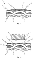
- FIG. 1 shows a cross section through a thermoset component 1 which comprises a base body 2 and a functional layer 3.
- the thermoset component 1 is embodied in the present case as a fiber-reinforced thermoset component.
- the base body 2 thus comprises reinforcing fibers 4 which are embedded in a matrix 5 made of plastic.
- the reinforcing fibers can be glass, carbon and / or aramid fibers.
- the reinforcing fibers 4 are designed as carbon fibers.
- the carbon fibers can be designed as short cut fibers, short cut threads, tapes or, as in the present case, as a fabric mat in the base body 2.
- the reinforcing fibers are introduced as a scrim, that is to say at least two fabric mats placed one on top of the other.
- the matrix 5 is a thermosetting plastic, in particular an epoxy resin or polyurethane resin.
- the thermosetting matrix 5 is cured in the present case and gives the reinforcing fibers 4 dimensional stability.
- the reinforcing fibers 4 primarily serve to give the base body 2 or the thermoset component 1 the necessary strength.
- the thermosetting base body 2 can have any shape. So
- the base body 2 can be a body part of a vehicle or an interior lining of such a vehicle.
- Such duroplastic base bodies or duroplastic components usually have a complex component geometry, in particular with free-form surfaces and / or undercuts.
- thermoset components A fundamental problem with such thermoset components is that, after they have hardened, they can only be connected to other components in very complex and expensive processes. These methods also have the disadvantage that the connection quality is not particularly good, so that there is a risk that the two components will detach from one another when loaded.
- thermoset component 1 according to Figure 1 therefore the functional layer 3.
- the functional layer 3 is a thermoplastic or a mixture of a thermoplastic and a thermosetting plastic.
- the proportion of thermoset to thermoplastic is preferably 1/4, 1/3, 1/2 or, particularly preferably, 1/1.
- the functional layer 3 is directly connected to the base body 2 by means of adhesion, in particular glued.
- An adhesion interface 6 is thus formed between the functional layer 3 and the base body 2.
- the functional layer 3 can here as in Figure 1 shown exclusively with the thermosetting matrix 5 of the base body or additionally or alternatively with the reinforcing fibers 4.
- the adhesion interface 6 represents a clear transition from the thermosetting matrix 5 to the thermoplastic / thermosetting functional layer 3 Diffusion area formed. Also, no connecting means, in particular adhesive and / or primer, is arranged.
- the functional layer 3 is in a joining area 7a of the thermoset component 1 arranged. On its side facing away from the base body 2, the functional layer 3 has a connection surface 8 on which the thermoset component 1 can be connected, in particular welded, to a thermoplastic component 9 provided for this purpose (cf. Figure 2 and 3 ).
- the thermoset component 1 can also have several joining regions 7a designed in this way, in which it can be connected, in particular welded, to one or more thermoplastic components 9.
- the functional layer 3 is very thin. It preferably has a thickness of 10 ⁇ m to 1,000 ⁇ m, in particular 150 ⁇ m to 750 ⁇ m. However, a very thin functional layer 3 with a thickness of 10 ⁇ m to 250 ⁇ m, in particular up to 200 ⁇ m, particularly preferably up to 150 ⁇ m, is particularly preferred.
- Such thin functional layers can be formed by a spraying process.
- the reinforcing fibers 4, in particular carbon fibers are introduced with the viscous thermosetting matrix 5 into a curing device (not shown here).
- a curing device can for example be an oven, an autoclave or a vacuum press.
- the thermosetting matrix 5 is cured and / or cured under pressure and / or heat.
- the functional layer 3 is provided in the joining area 7a in which the thermoset component 1 is to be connected, in particular welded, to the thermoplastic component 9 provided for this purpose.
- thermoplastic forming the functional layer 3 or the thermoplastic / thermosetting mixture can be sprayed onto a mold of the curing device, not shown here.
- thermoplastic and / or thermosetting plastic with which the functional layer 3 is formed is sprayed on in that area of the tool mold which is in contact with the joining area 7a of the base body 2 during the hardening process.
- Contact between the functional layer 3 and the base body 2 can take place after the functional layer 3 has been sprayed onto the mold by inserting the reinforcing fibers 4 together with the viscous thermosetting matrix 5, in particular as prepreg, into the mold. Alternatively, however, contact can also only take place when the tool is closed and / or when the viscous thermosetting matrix 5 is injected into the closed tool.
- the very firm adhesion interface 6, by means of which the functional layer 3 is connected to the base body 2, is formed during the subsequent hardening process, with no additional adhesives and / or primers being used.
- An essential advantage of the method in which the functional layer 3 is sprayed on is that the functional layer 3 rests on the base body 2 over the entire surface. This is particularly noticeable in the case of a complex component geometry, since in this case a functional layer 3 designed as a film would form so-called dry spots, which would ultimately weaken the connection between functional layer 3 and base body 2.
- thermoset of the functional layer 3 is particularly characterized in that the thermosetting portions of the functional layer 3 are higher in the area of the adhesion interface 6 than in the area of the connecting surface 8 provided for connecting to the thermoplastic component 9 provided for this purpose a very strong bond between functional layer 3 and base body 2 is promoted if the thermoset of the thermoplastic / thermoset functional layer 3 is the same or at least largely similar to that of the thermoset matrix 5.
- Epoxy resins or polyurethane resins are preferably suitable as thermosets for this purpose.
- Figure 2 shows in cross section a partial area of the fiber-reinforced thermoset component 1 before the connection, in particular welding, to the thermoplastic component 9.
- the fiber-reinforced thermoset component 1 can be inserted as an insert into an injection molding device (not shown here) and by directly injecting the thermoplastic component 9, which is a thermoplastic melt, in the area of the Joining area 7a of the thermoset component 1 are joined to this, in particular welded.
- the thermoplastic melt thus connects, in particular welded, to the functional layer 3 of the thermoset component 1 and at the same time forms the thermoplastic component 9 in its final form as a functional element in interaction with the injection mold.
- thermoplastic component 9 especially designed as a functional element, can also be preheated and / or melted in areas in its joining area 7b and, during or after this preheating and / or melting process, with its melted joining area 7b on the functional layer 3 of the thermoset component 1 in it Joining area 7a are pressed on.
- the thermoplastic component 9 is fused with the functional layer 3.
- the functional layer 3 can also be preheated and / or melted. This joining process can take place in a joining device designed for this purpose.
- thermoplastic component 9 with the fiber-reinforced thermoset component 1 is connected, in particular welded, the connection between these two components being effected by the functional layer 3.
- thermoset component 1 a diffusion area 11 is formed between the functional layer 3 of the thermoset component 1 and the thermoplastic component 9.
- This diffusion region 11 is designed to be particularly solid if the thermoplastic of the thermoplastic component 9 is the same or at least largely similar to that of the thermoplastic / thermosetting functional layer 3.
- Any industrially usable thermoplastic is suitable for this. However, ABS and / or a polyamide, in particular polyamide 11 and / or 12, is particularly preferred.
- thermoset base body 2 of the thermoset component 1 and the thermoplastic component 9 connected to it are thus spaced apart from one another by a remaining part of the thermoplastic / thermoset functional layer 3.
- the joining areas 7a, 7b of the two components are shown in FIG Figure 3 fused into one another and thereby form the diffusion area 11, which ensures a very firm connection between the thermoplastic component 9 and the thermoset component.
- the Figures 1 to 3 each show only a section of a thermoset component 1 and / or a thermoplastic component 9 or a composite component 10 comprising these two components.
- the thermoset component 1 can have several joining areas 7a designed in this way in which it can be or is connected to one or more thermoplastic components 9.
- the thermoplastic components 9 are preferably functional elements, in particular stiffening struts and / or fastening areas, preferably clips, eyes or the like. It is also conceivable that the thermoset component 1 is coated over the entire surface with a corresponding functional layer 3. For this purpose, it is advisable to use the thermoset component 1, in particular its base body 2 its hardening to be sprayed over the entire surface with a thermoplastic present as a liquid, paste, powder and / or granulate to form the functional layer 3.
Landscapes
- Engineering & Computer Science (AREA)
- Mechanical Engineering (AREA)
- Chemical & Material Sciences (AREA)
- Composite Materials (AREA)
- Laminated Bodies (AREA)
- Lining Or Joining Of Plastics Or The Like (AREA)
Description
- Die vorliegende Erfindung betrifft ein Herstellungsverfahren für ein faserverstärktes Duroplastbauteil, das mit einem Thermoplastbauteil stoffschlüssig verbindbar, insbesondere verschweißbar, ist, bei welchem zur Ausbildung eines Grundkörpers Verstärkungsfasern mit einer viskosen duroplastischen Matrix in eine Aushärtevorrichtung eingebracht werden und die duroplastische Matrix unter Druck und/oder Hitze angehärtet und/oder ausgehärtet wird, wobei vor oder während dieses Härteprozesses zum Beschichten des Grundkörpers, zumindest in einem zum Verbinden mit dem Thermoplastbauteil vorgesehen Fügebereich, eine Funktionsschicht an der viskosen duroplastischen Matrix und/oder den Verstärkungsfasern angeordnet wird, die sich während des Härteprozesses fest mit der duroplastischen Matrix und/oder den Verstärkungsfasern verbindet.
- Des Weiteren betrifft die Erfindung ein derart hergestelltes Duroplastbauteil, das mit einem Thermoplastbauteil stoffschlüssig verbindbar, insbesondere verschweißbar, ist, wobei das Duroplastbauteil einen Grundkörper aufweist, der in einer ausgehärteten duroplastischen Matrix eingebundene Verstärkungsfasern umfasst und zumindest in einem zum Verbinden mit dem Thermoplastbauteil vorgesehen Fügebereich mit einer Funktionsschicht beschichtet ist.
- Die Erfindung betrifft ferner ein Verbundbauteil mit einem derart hergestellten und ausgebildeten Duroplastbauteil.
- Faserverbundbauteile gewinnen aufgrund ihrer Festigkeit und geringen Gewichts insbesondere in der Luftfahrt-, Raumfahrt- und Automobiltechnik mehr und mehr an Bedeutung. Hierbei finden insbesondere glasfaserverstärkter Kunststoff (GFK) und in zunehmenden Maße carbonfaserverstärkter Kunststoff (CFK) Verwendung.
- Faserverstärkte Bauteile weisen Verstärkungsfasern, insbesondere Carbonfasern, Glasfasern und/oder Aramidfasern, auf, die in einer, insbesondere themoplastischen und/oder duroplastischen, Matrix eingebettet bzw. eingebunden sind. Hierbei verleihen insbesondere die Verstärkungsfasern dem Bauteil die nötige Festigkeit bzw. Steifigkeit. Die Matrix hat hingegen die primäre Wirkung, die Verstärkungsfasern in einer gewünschten Form zu halten. Die Verstärkungsfasern werden somit durch die Matrix ausgerichtet, unterstützt sowie geschützt.
- Aufgrund der besseren mechanischen Fähigkeiten - vor allem im Hinblick auf die gewichtsspezifische Festigkeit und Steifigkeit - werden faserverstärkte Bauteile mit einer duroplastischen Matrix in vielen Anwendungsfällen bevorzugt. Die Vernetzung der Duroplaste bezeichnet man als Aushärtung. Hierbei kann es sich um eine vernetzende Polymerisation oder beispielsweise eine Polyaddition oder Polykondensation handeln. Da Duroplaste bzw. die duroplastische Matrix nach dem Härteprozess nicht mehr aufgeschmolzen werden kann, muss die Formgebung des faserverstärkten Duroplastbauteils vor oder während dieses Härteprozesses erfolgen. Des Weiteren ist ein unmittelbares Verschweißen eines ausgehärteten Duroplastbauteils mit einem anderen Bauteil, insbesondere Thermoplastbauteil, aufgrund dieser Eigenschaft nicht möglich.
- Ein aus dem Stand der Technik bekanntes Fügeverfahren ist beispielsweise das Verkleben von Duroplastbauteilen mit Thermoplastbauteilen unter Verwendung eines Klebstoffes und/oder Haftvermittlers, insbesondere eines Primers. Nachteilig ist hierbei jedoch die lange Prozessdauer durch zusätzliche Prozessschritte und die daraus resultierenden erhöhten Kosten.
- Ferner sind bekannte Fügeverfahren das form- und/oder kraftschlüssige Verbinden derartiger Bauteile. So können diese beispielsweise mittels Schrauben und/oder Nieten miteinander verbunden werden. Nachteilig hierbei jedoch ist, dass die Faserstruktur des faserverstärkten Duroplastbauteils beim Ein- und/oder Durchdringen der Befestigungsmittel beschädigt wird. Hierdurch verliert das Bauteil an Festigkeit. Alternativ oder zusätzlich können Duroplastbauteile natürlich auch nach dem Aushärten beispielsweise mit einem Thermoplastbauteil formschlüssig umspritzt werden. Jedoch kann auch auf diese Weise oft keine ausreichend feste Verbindung zwischen den beiden Bauteilen ausgebildet werden. Ferner haben alle diese vorstehend genannten Verbindungsverfahren den Nachteil, dass diese sehr aufwendig und teuer sind.
- Aus der
WO 2007/109855 A1 ist ein Faserverbundbauteil bekannt, das mehrere übereinander angeordnete Prepreg-Schichten umfasst. Mit der letzten Prepreg-Schicht wird eine thermoplastische Funktionsschicht verbunden. - Aus der
EP 2 594 375 A1 ist ein Verfahren zur Demontage von zwei durch Ultraschall geschweißten Elementen bekannt, wobei eines der Elemente auf einer dem anderen Element zugewandten Seite einen Energierichtungsgeber aufweist, der die Erwärmung während des Ultraschallschweißens fokussiert und der eine Materialverbindung zwischen den beiden nach dem Ultraschallschweißen zusammengefügten Elementen bildet. Das Verfahren umfasst das Positionieren eines Drahtes zwischen den beiden zusammengesetzten Elementen, der den Energieleiter so schneidet, wobei der Draht geeignete mechanische Eigenschaften aufweist, die es ihm ermöglichen, die durch den Energieleiter gebildete Verbindung zu durchtrennen und den Draht zwischen den beiden zusammengesetzten Elementen zu verschieben, um die Verbindung zu durchtrennen. - Aus der
US 2011/0240200 A1 ist ein Verfahren zur Bildung einer Verbindung zwischen einer ersten Komponente und einer zweiten Komponente bekannt, wobei die erste Komponente eine Vielzahl von Schichten von Fasern umfasst, die mit einer wärmehärtbaren Matrix imprägniert sind. Ein Schweißschnittstellenelement wird mit einer Anordnung von spitzen Zacken versehen. Eine oder mehrere der Faserschichten werden entweder vor oder nach der Imprägnierung der Fasern mit der wärmehärtenden Matrix mit den Zinken durchdrungen. Die erste Komponente wird durch Erhitzen der wärmehärtenden Matrix ausgehärtet, nachdem die Zinken eingebettet wurden. Es entsteht eine thermoplastische Schweißnaht zwischen der zweiten Komponente und dem Schweißschnittstellenelement. - Aus der
EP 1 767 335 A2 ist eine Methode und eine Vorrichtung zum Verbinden von Verbundwerkstoffen mit thermoplastischen Oberflächen bekannt. Das Verfahren umfasst die Anordnung der genannten Komponenten innerhalb eines tragenden Rahmens und das In-Kontakt-Bringen der zu verbindenden thermoplastischen Oberflächen. Druckanwendungsvorrichtungen in Form von mit Flüssigkeit gefüllten Blasen sind ebenfalls innerhalb des Rahmens angeordnet und so angeordnet, dass der Druck gleichmäßig auf die thermoplastischen Oberflächen ausgeübt wird. Wenn die Komponenten ein hohes Maß an Krümmung oder Verdrehung aufweisen, sind zwischen dem Rahmen und den Blasen Formblöcke angeordnet, die die ungefähre Form der Komponentenoberfläche haben. Druck und Wärme werden auf den Verbindungsbereich aufgebracht und die Wärme wird abgeführt, während der Verbindungsbereich unter einem gewissen Druck gehalten wird. - Aus der
WO 2012/161569 A1 ist ein Verfahren zum Verbinden eines thermoplastischen Polymers mit einer wärmehärtbaren Polymerkomponente bekannt, wobei das thermoplastische Polymer eine Schmelztemperatur hat, die die Aushärtungstemperatur des wärmehärtbaren Polymers übersteigt. Das Verfahren umfasst die Schritte des Bereitstellens einer ausgehärteten wärmehärtbaren Polymerkomponente, die ein Implantat aus einem thermoplastischen Polymer zumindest an dem zu verbindenden Teil der wärmehärtbaren Polymerkomponente umfasst, des Anordnens eines thermoplastischen Polymers in Kontakt mit zumindest dem zu verbindenden Teil, des Erhitzens der Anordnung auf die Schmelztemperatur des thermoplastischen Polymers, wodurch das thermoplastische Polymer des Implantats schmilzt und mit dem thermoplastischen Polymer verschmilzt, und des Abkühlens der Anordnung. Das thermoplastische Polymer hat eine Schmelztemperatur, die die Aushärtungstemperatur des wärmehärtbaren Polymers übersteigt, und das Implantat ist so ausgelegt, dass eine Erwärmung über die maximale Betriebstemperatur des wärmehärtbaren Polymers an der Grenzfläche des Implantats mit der Komponente des wärmehärtbaren Polymers während des Verbindungsschritts vermieden wird. - Aus der
DE 10 2010 007 824 A1 ist ferner ein Herstellungs- und Fügeverfahren für duroplastische Kohlenstofffaserverbundbauteile bekannt, das einen technisch zuverlässigen Verbund mit Hilfe eines Widerstandsschweißverfahrens bereitstellt. Für das Widerstandsschweißen werden Kohlenstofffasertextilien mit Gewebestruktur oder Fließstruktur als Heizelemente verwendet, die zwischen den beiden zu verbindenden Bauteilen angeordnet werden. Die Kohlenstofffasertextilien sind auf ihrer Oberfläche mit einem Thermoplast imprägniert oder mit diesem durchgehend getränkt. Mit Hilfe jeweils eines solchen imprägnierten Kohlenstofffasertextils werden zwei duroplastische Bauteile oder ein duroplastisches mit einem thermoplastischen Bauteil über eine am duroplastischen Bauteil intermolekular angebundene Thermoplastfolie unter Druck und erhöhter Temperatur verschweißt. - Die Verwendung einer Folie hat jedoch den Nachteil, dass insbesondere bei komplexen Bauteilstrukturen nicht sichergestellt werden kann, dass die Anbindungs-Folie vollflächig an dem Duroplastbauteil anliegt. Diese sogenannten Trockenstellen schwächen den Verbindungsbereich zwischen dem Duroplastbauteil und dem damit verbundenen Bauteil. Des Weiteren gestaltet sich das Herstellungsverfahren unter Verwendung einer derartigen Folie sehr aufwendig und teuer.
- Ein weiterer Nachteil dieses bekannten Verbindungsverfahren besteht darin, dass zwischen den beiden miteinander zu verbinden Bauteilen stets ein imprägniertes Kohlenstofffasertextil eingebracht werden muss. Hierdurch gestaltet sich die Verbindung des Duroplastbauteils mit einem Thermoplastbauteil sehr aufwendig und teuer. Des Weiteren besteht insbesondere bei komplexen Bauteilstrukturen die Gefahr, dass das im Verbindungsbereich angeordnete imprägnierte Kohlenstofffasertextil Falten wirft, wodurch Trockenstellen zwischen dem Kohlenstofffasertextil und zumindest einem der beiden miteinander zu verbindenden Bauteile ausgebildet werden, die wiederum zu einer Schwächung des Verbindungsbereiches führen.
- Aufgabe der vorliegenden Erfindung ist es somit, ein Herstellungsverfahren für ein faserverstärktes Duroplastbauteil mit einer Funktionsschicht bereitzustellen, ein derart hergestelltes faserverstärktes Duroplastbauteil sowie ein Verbundbauteil mit einem derart hergestellten und ausgebildeten Duroplastbauteil zu schaffen, mittels dem die oben genannten Nachteile gelöst werden können.
- Die Aufgabe wird gelöst durch ein Herstellungsverfahren für ein faserverstärktes Duroplastbauteil mit den Merkmalen des unabhängigen Anspruches 1, mit einem Duroplastbauteil, das mit einem Thermoplastbauteil stoffschlüssig verbindbar ist, mit den Merkmalen des unabhängigen Anspruches 6sowie ein Verbundbauteil mit den Merkmalen des unabhängigen Anspruches 12.
- Vorgeschlagen wird ein Herstellungsverfahren für ein zumindest angehärtetes, insbesondere vollständig ausgehärtetes, faserverstärktes Duroplastbauteil, das mit einem dafür vorgesehenen Thermoplastbauteil stoffschlüssig verbindbar ist. Bei diesem Herstellungsverfahren wird vor oder während eines Härteprozesses auf einem noch ungehärteten duroplastischen Grundkörper zumindest in einem zum Verbinden mit dem Thermoplastbauteil vorgesehenen Fügebereich eine thermo-/duroplastische Funktionsschicht aufgebracht. Der duroplastische Grundkörper umfasst hierbei Verstärkungsfasern, insbesondere Carbonfasern, und eine viskose duroplastische Matrix. Der zumindest teilweise beschichtete Grundkörper wird in einer Aushärtevorrichtung unter Druck und/oder Hitze angehärtet und/oder ausgehärtet. Des Weiteren wird dieser hierbei vorzugsweise in seine gewünschte Endform gebracht. Während dieses Härteprozesses verbindet sich die thermo-/duroplastische Funktionsschicht stoffschlüssig mit der duroplastischen Matrix und/oder den Verstärkungsfasern des Grundkörpers. Mittels der thermo-/duroplastischen Funktionsschicht kann der angehärtete oder vollständig ausgehärtete duroplastische Grundkörper nach Beendigung seines Herstellungsverfahrens in einem anschließenden Fügeverfahren mit dem dafür vorgesehenen Thermoplastbauteil verbunden werden.
- Vorgeschlagen wird somit im Wesentlichen ein Herstellungsverfahren für ein faserverstärktes Duroplastbauteil, das mit einem Thermoplastbauteil stoffschlüssig verbindbar, insbesondere verschweißbar, ist. Bei dem erfindungsgemäßen Herstellungsverfahren werden zur Ausbildung eines Grundkörpers Verstärkungsfasern, insbesondere Carbon-, Glas- und/oder Aramidfasern, mit einer viskosen duoplastischen Matrix in eine Aushärtevorrichtung eingebracht. Die Verstärkungsfasern können in Form von Kurzschnittfasern, Kurzschnittfäden, Bändern, Gewebematten, Gelegen und/oder Prepregs bereitgestellt werden. Hierbei bezeichnet der Begriff Prepreg Bänder oder Gewebematten oder Gewebegelege, die mit einem Harz vorzugsweise mit einem duroplastischen Matrixwerksstoff vorimprägniert und/oder gegebenenfalls vorgehärtet sind. Der für die duroplastische Matrix verwendete Werkstoff, ist insbesondere ein Epoxidharz oder Polyurethanharz, besonders bevorzugt ein ein-, zwei- oder dreikomponentiges Harz. Die Aushärtevorrichtung kann ein Ofen, ein Autoklav oder eine Vakuumpresse sein. Es ist aber auch jegliche andere Vorrichtung denkbar, die dazu geeignet ist die duroplastische Matrix anzuhärten und/oder auszuhärten.
- Das Einbringen der Verstärkungsfasern und der duroplastischen Matrix kann ebenfalls auf unterschiedlichste Art und Weise erfolgen. So ist es beispielsweise denkbar, dass die Verstärkungsfasern einzeln, als Gewebe und/oder als Gelege in die Aushärtevorrichtung eingebracht werden und anschließend durch das Einspritzen der viskosen duroplastischen Matrix mit dieser umgeben und/oder getränkt werden. Alternativ oder zusätzlich kann die Kombination aus Verstärkungsfasern und duroplastischer Matrix aber auch als Prepreg in die Aushärtevorrichtung eingebracht werden. Selbstverständlich können auch mehrere derartige Lagen in die Aushärtevorrichtung, insbesondere auf eine Werkzeugform, aufgebracht werden.
- Nachdem die Verstärkungsfasern und die viskose duroplastische Matrix in die Aushärtevorrichtung eingebracht wurde, wird die duroplastische Matrix unter Druck und/oder Hitze angehärtet und/oder ausgehärtet. Vor oder während dieses Härteprozesses wird zum Beschichten des Grundkörpers, zumindest in einem zum Verbinden mit dem Thermoplastbauteil vorgesehen Fügebereich, eine Funktionsschicht an der, insbesondere viskosen, duroplastischen Matrix und/oder an den Verstärkungsfasern angeordnet. Alternativ kann aber auch der gesamte Grundkörper mit einer derartigen Funktionsschicht überzogen werden. Die Funktionsschicht verbindet sich während des Härteprozesses stoffschlüssig mit der duroplastischen Matrix und/oder den Verstärkungsfasern.
- Erfindungsgemäß wird die Funktionsschicht vor oder während des Härteprozesses auf die, insbesondere viskose, duroplastische Matrix und/oder die Verstärkungsfasern zumindest in dem Fügebereich bzw. in einem diesen Fügebereich bildenden Bereich des Verstärkungsfasern-Matrix-Verbundes aufgebracht, vorzugsweise aufgesprüht. Alternativ oder zusätzlich kann die Funktionsschicht aber auch, insbesondere vor dem Schließen der Aushärtevorrichtung, auf eine Werkzeugform der Aushärtevorrichtung zumindest in einem während des Härteprozesses an dem Fügebereich des Grundkörpers bzw. Duroplastbauteils anliegenden Bereich, gesprüht werden. Durch das Aufsprühen der Funktionsschicht können vorteilhafterweise Trockenstellen vermieden werden, in deren Bereich die Funktionsschicht nicht vollflächig am Grundkörper anliegt. Derartige Trockenstellen treten insbesondere bei komplexen Bauteilstrukturen auf, wenn als Funktionsschicht eine Folie verwendet wird. Durch das Aufsprühen der Funktionsschicht kann eine vollflächige und somit sehr feste Verbindung zwischen der Funktionsschicht und dem Grundkörper im Fügebereich sichergestellt werden. Ferner kann das faserverstärkte Duroplastbauteil, das zum Verschweißen mit einem Thermoplastbauteil geeignet ist, durch das Aufsprühen der Funktionsschicht sehr kostengünstig und schnell hergestellt werden.
- Vorteilhaft ist es, wenn die Funktionsschicht als Flüssigkeit, Paste, Pulver und/oder Granulat aufgebracht, insbesondere aufgesprüht, wird. Hierdurch kann besonderes gut die Dicke der Funktionsschicht reguliert werden.
- Ebenso ist es vorteilhaft, wenn die Funktionsschicht mehrschichtig ausgebildet ist, insbesondere mit einer im Wesentlichen duroplastischen ersten Schicht, einer im Wesentlichen thermoplastischen zweiten Schicht und/oder einer zwischen diesen beiden angeordneten thermo-/duroplastischen Mischschicht. Besonders bevorzugt ist es, wenn die erste Schicht mit dem Grundkörper die Adhäsions-Grenzfläche und die zweite Schicht die Verbindungsfläche zum Verbinden, insbesondere Verschweißen, mit dem dafür vorgesehenen Thermoplastbauteil ausbildet. Vorteilhafterweise werden die Schichten nacheinander auf die Werkzeugform und/oder den Grundkörper aufgebracht, insbesondere aufgesprüht.
- Auch ist es vorteilhaft, wenn die Viskosität des aufgesprühten Materials, das die Funktionsschicht bildet, derart gewählt wird, dass das Material die Werkzeugform und/oder den Grundkörper, insbesondere bei einer komplexen Bauteilgeometrie, geleichmäßig benetzt und/oder im Wesentlichen nicht wegzufließen vermag, wodurch die Funktionsschicht vor oder während des Härteprozesses aufreißen würde.
- Eine ausreichend feste Verbindung zwischen der Funktionsschicht und der duroplastischen Matrix und/oder den Verstärkungsfasern kann sichergestellt werden, wenn sich die Funktionsschicht mit der duroplastischen Matrix und/oder den Verstärkungsfasern während des Härteprozesses durch Adhäsion verbindet. Die duroplastische Matrix und/oder die Verstärkungsfasern sind somit mit der Funktionsschicht unmittelbar angebunden, insbesondere verklebt, ohne die Verwendung von Zusatzmitteln, wie beispielsweise einem Klebstoff und/oder Primer. Zwischen der Funktionsschicht und der duroplastischen Matrix und/oder den Verstärkungsfasern wird somit eine Adhäsions-Grenzfläche ausgebildet. Die Funktionsschicht weist hierdurch eine sehr feste Verbindung mit der duroplastischen Matrix und/oder den Verstärkungsfasern auf, so dass ein Ablösen der Funktionsschicht vom Grundkörper im Wesentlichen ausgeschlossen ist.
- Vorteilhaft ist es, wenn bei der Ausbildung der Adhäsions-Grenzfläche die duroplastischen Anteile der thermo-/duroplastischen Funktionsschicht während des Härteprozesses in Richtung der Adhäsions-Grenzfläche und die thermoplastischen Anteile von dieser weg wandern. Hierdurch kann eine stärkere Bindung zwischen der Funktionsschicht und dem Grundkörper sowie dem dafür vorgesehenen Thermoplastbauteil bewirkt werden.
- Vorteilhafterweise wird die duroplastische Matrix in einem Nassimprägnierverfahren, insbesondere vor dem Aufsprühen der Funktionsschicht, auf die Verstärkungsfasern aufgesprüht, in einem Injektionsverfahren, insbesondere nach dem Aufsprühen der Funktionsschicht, in die Aushärtevorrichtung eingespritzt und/oder zusammen mit den Verstärkungsfasern als Prepreg in die Aushärtevorrichtung eingebracht.
- Ebenso ist es vorteilhaft, wenn die Werkzeugform der Aushärtevorrichtung vor dem Aufsprühen der Funktionsschicht vorgewärmt und/oder während des Härteprozesses auf einer, vorzugsweisen konstanten, Temperatur gehalten wird. Bevorzugt ist es, wenn die Temperatur höher oder gleich der Aushärtetemperatur der duroplastischen Matrix und/oder des in der Funktionsschicht verwendeten Duroplasten, vorzugsweise zwischen 100 °C und 200 °C, besonders bevorzugt 120 °C, und niedriger als die Schmelztemperatur des in der Funktionsschicht verwendeten Thermoplasten, vorzugsweise zwischen 100 °C und 300 °C, besonders bevorzugt 200 °C, ist. Aufgrund dessen, dass die Schmelztemperatur des Thermoplasten höher ist als die Aushärtetemperatur des Duroplasten härtet der Duroplast aus, ohne dass der Thermoplast vollständig aufschmilzt. Vorteilhafterweise kann somit vermieden werden, dass die Funktionsschicht bereichsweise aufreißt, da ein über die Schmelztemperatur erhitzter Thermoplast aufgrund seiner hierdurch steigenden Viskosität wegfließen würde. Ein weiterer Vorteil der vorstehend genannten Temperaturbereiche besteht darin, dass insbesondere bei einer thermo-/duroplastischen Funktionsschicht die auf die Aushärtetemperatur erhitzten Duroplaste vermehrt in Richtung des Grundkörpers, d.h. in Richtung der auszubildenden Adhäsions-Grenzfläche, wandern, wohingegen die thermoplastischen Anteile der Funktionsschicht vermehrt in Richtung der Fügefläche wandern, in deren Bereich das faserverstärkte Duroplastbauteil zu einem späteren Zeitpunkt mit dem dafür vorgesehen Thermoplastbauteil verbunden, insbesondere verschweißt werden kann. Hierdurch wird vorteilhafterweise zwischen der Funktionsschicht und dem faserverstärkten Duroplastbauteil die Klebeverbindung im Bereich der Adhäsions-Grenzfläche fester. Zugleich wird aber auch die Verbindungsqualität des faserverstärkten Duroplastbauteils mit dem dafür vorgesehenen Thermoplastbauteil durch die höhere Thermoplastkonzentration im Fügebereich der Funktionsschicht verbessert.
- Erfindungsgemäß weist das Duroplastbauteil, das mit einem Thermoplastbauteil verbindbar, insbesondere verschweißbar, ist, einen Grundkörper auf, der in einer ausgehärteten duroplastischen Matrix eingebundene Verstärkungsfasern, insbesondere Carbon-, Glas- und/oder Aramidfasern, umfasst und der zumindest in einem zum Verbinden mit dem Thermoplastbauteil vorgesehen Fügebereich mit einer Funktionsschicht ausgebildet, insbesondere beschichtet, ist. Die Funktionsschicht ist eine thermo-/duroplastische Funktionsschicht. Vorteilhafterweise kann somit das Duroplastbauteil schnell und unkompliziert im Rahmen eines Schweißverfahrens oder Spritzgießverfahrens mit einem Thermoplastbauteil verbunden werden.
- Eine besonders feste Verbindung zwischen dem Grundkörper und der Funktionsschicht sowie zwischen der Funktionsschicht und dem zum Verbinden, insbesondere Verschweißen, mit dieser bzw. mit dem Duroplastbauteil vorgesehenen Thermoplastbauteil kann mit einer thermo-/duroplastischen Funktionsschicht sichergestellt werden. So bewirken insbesondere die Duroplaste der Funktionsschicht die Ausbildung einer besonders festen Verbindung, insbesondere Klebeverbindung, zwischen dem im Wesentlichen duroplastischen Grundkörper und der Funktionsschicht. Zugleich bewirken die Thermoplaste der Funktionsschicht ein Verbinden, insbesondere Verschweißen, mit dem dafür vorgesehenen Thermoplastbauteil unter Ausbildung eines besonders festen Stoffschlusses, insbesondere einer Schweißverbindung.
- Vorteilhafterweise ist die Funktionsschicht eine Sprühschicht oder eine Folie. Eine als Sprühschicht ausgebildete Funktionsschicht zeichnet sich insbesondere dadurch aus, dass zwischen dieser und dem Grundkörper im Wesentlichen keine Trockenstellen ausgebildet sind. Infolgedessen liegt die Funktionsschicht bzw. die Sprühschicht vollflächig am Grundkörper an. Vorzugsweise ist die Sprühschicht nach einem Herstellungsverfahren gemäß der vorstehenden Beschreibung ausgebildet, wobei die genannten Merkmale einzeln oder in beliebiger Kombination vorhanden sein können.
- Eine besonders feste Verbindung zwischen der Funktionsschicht und dem Grundkörper kann sichergestellt werden, wenn zwischen diesen beiden eine Adhäsions-Grenzfläche ausgebildet ist. Die Funktionsschicht ist mit dem Grundkörper, insbesondere mit der duroplastischen Matrix und/oder den Verstärkungsfasern, somit unmittelbar verbunden, insbesondere verklebt.
- Auch ist es vorteilhaft, wenn der Duroplast der thermo-/duroplastischen Funktionsschicht mit dem der duroplastischen Matrix gleich oder zumindest weitestgehend ähnlich ist. Hierdurch kann eine sehr feste Verbindung zwischen der Funktionsschicht und dem Grundkörper, insbesondere dessen duroplastischer Matrix und/oder Verstärkungsfasern, sichergestellt werden.
- Vorzugsweise ist der in der Funktionsschicht verwendete Thermoplast Acrylnitril-Butadien-Styrol (ABS) oder Polyamid, insbesondere Polyamid 11 oder 12. Alternativ ist aber auch ebenso jeder andere technisch verwendbare Thermoplast denkbar. Als Duroplast wird ein, insbesondere ein-, zwei- oder dreikomponentiges, Epoxidharz oder Polyurethanharz bevorzugt.
- Um eine hochfeste Verbindung der Funktionsschicht am Grundkörper sicherzustellen und zugleich die Eigenschaften dieser Funktionsschicht zum Verbinden mit dem dafür vorgesehen Thermoplastbauteil dahingehend zu optimieren, dass die Funktionsschicht eine besonders feste Verbindung zwischen dem Thermoplastbauteil und dem faserverstärkten Duroplastbauteil ausbildet, ist es vorteilhaft, wenn der Duroplastanteil der thermo-/duroplastischen Funktionsschicht im Bereich der Adhäsions-Grenzfläche größer ist als im Bereich ihrer zum Fügen mit dem Thermoplastbauteil vorgesehenen Verbindungsfläche. So bewirken die im Verbindungsbereich mit dem Grundkörper in höherer Konzentration vorhandenen Duroplastteilchen der thermo-/duroplastischen Funktionsschicht, dass die Funktionsschicht besonders fest mit der duroplastischen Matrix des faserverstärkten Grundkörpers verbunden, insbesondere verklebt, ist. Zugleich verbessern die an der Verbindungsoberfläche der Funktionsschicht mit höherer Konzentration vorhandenen Thermoplastteilchen, dass sich die Funktionsschicht besonders fest mit dem dafür vorgesehen Thermoplastbauteil verbindet.
- Vorteilhafterweise ist der Thermoplastanteil der thermo-/duroplastischen Funktionsschicht höher oder gleich dem Duroplastanteil. So ermöglichen insbesondere die Thermoplastanteile der thermo-/duroplastischen Funktionsschicht ein Verbinden, insbesondere Verschweißen, des ausgehärteten faserverstärkten Duroplastbauteils mit dem dafür vorgesehen Thermoplastbauteil. Bei einem zueinander im Wesentlichen ausgeglichenen Verhältnis von Thermoplaste zu Duroplaste kann vorteilhafterweise eine sehr feste Klebeverbindung zwischen der Funktionsschicht und dem faserverstärkten Duroplastbauteil sowie eine besonders feste Verbindung, insbesondere Schweißverbindung, der Funktionsschicht mit dem dafür vorgesehen Thermoplastbauteil sichergestellt werden.
- In einer vorteilhaften Weiterbildung der Erfindung weist die Funktionsschicht, insbesondere über ihre gesamte Fläche, eine Dicke von 10 µm bis 1000 µm, insbesondere von 150 µm bis 750 µm, auf. Die Funktionsschicht weist besonders bevorzugt im Wesentlichen über ihre gesamte Fläche eine homogene Dicke auf. Hierdurch kann sichergestellt werden, dass beim Aufschweißen des dafür vorgesehen Thermoplastbauteils die Funktionsschicht nicht vollständig durchschmolzen wird, so dass das Thermoplastbauteil unmittelbar am Duroplastbauteil anliegen würde. Dies hätte nämlich eine Schwächung des Verbindungsbereiches zwischen den beiden, insbesondere miteinander verschweißten, Bauteilen zur Folge. Insbesondere durch das Sprühverfahren kann eine besonders dünne Funktionsschicht ausgebildet werden. Durch eine sehr dünne Funktionsschicht können die Herstellungskosten des faserverstärkten Duroplastbauteils reduziert werden.
- Ferner können insbesondere durch das vorstehend erwähnte Sprühverfahren Trockenstellen zwischen der Funktionsschicht und dem Grundkörper vermieden werden. Vorteilhafterweise liegt die Funktionsschicht somit vollflächig an dem Grundkörper an, so dass die Funktionsschicht sehr fest mit dem Grundkörper, insbesondere über deren gesamten Kontaktbereich, verklebt ist.
- Vorteilhaft ist es, wenn das Duroplastbauteil bzw. der Grundkörper in mehreren voneinander beabstandeten oder zumindest teilweise überlappenden Bereichen mit einer Funktionsschicht beschichtet ist. Somit kann das Duroplastbauteil vorteilhafterweise an mehreren Stellen mit einem oder mehreren Thermoplastbauteilen verbunden, insbesondere verschweißt, werden. Auch ist es vorteilhaft, wenn die Funktionsschichten zueinander eine gleiche und/oder unterschiedliche Dicke aufweisen.
- In einem Verfahren zum Fügen eines Duroplastbauteils mit einem Thermoplastbauteil durch stoffschlüssige Verbindung, insbesondere Verschweißen, werden diese beiden Bauteile mittels einer Funktionsschicht des Duroplastbauteils miteinander verbunden. Hierbei wird das Thermoplastbauteil unmittelbar auf der Funktionsschicht des Duroplastbauteils angebunden, insbesondere aufgeschweißt, wobei zwischen dem Thermoplastbauteil und der Funktionsschicht des Duroplastbauteils ein Diffusionsbereich ausgebildet wird. Ein Diffusionsbereich zeichnet sich durch einen gleichmäßigen Materialübergang vom Thermoplastbauteil zur Funktionsschicht des Duroplastbauteils aus. Der Diffusionsbereich weist vorzugsweise eine Dicke von ca. 20 µm bis 40 µm auf. Der Diffusionsbereich gewährleistet eine sehr feste Verbindung zwischen dem aufgebrachten, insbesondere aufgeschweißten, Thermoplastbauteil und dem insbesondere faserverstärkten Duroplastbauteil. Ferner stellt dieses Fügeverfahren eine sehr kostengünstige und schnelle Verbindung von insbesondere faserverstärkten Duroplastbauteilen mit Thermoplastbauteilen dar.
- Das Duroplastbauteil ist gemäß der vorrangegangenen Beschreibung hergestellt und/oder ausgebildet, wobei die genannten Verfahrensschritte sowie Merkmale einzeln oder in beliebiger Kombination vorhanden sein können.
- Eine besonders schnelle und unkomplizierte Verbindung des Duroplastbauteils mit dem Thermoplastbauteil kann erfolgen, wenn das Thermoplastbauteil und/oder die Funktionsschicht des Duroplastbauteils, insbesondere bereichsweise, vorgewärmt und/oder aufgeschmolzen wird und das, vorzugsweise bereichsweise, aufgeschmolzene Thermoplastbauteil auf die Funktionsschicht des Duroplastbauteils gepresst wird.
- Alternativ kann das Duroplastbauteil, insbesondere in einem Spritzgießverfahren, aber auch als, insbesondere vorgehärteter oder ausgehärteter, Einleger in eine Spritzgussform eingelegt werden und anschließend, insbesondere bei geschlossenem Werkzeug, mit einer das Thermoplastbauteil bildenden Thermoplastschmelze verspritzt werden. Hierbei wird das Thermoplastbauteil als Thermoplastschmelze direkt auf die Funktionsschicht des Duroplastbauteils gespritzt. Dieses Herstellungsverfahren eignet sich besonders für komplexe Verbundbauteile mit einer durch das faserverstärkte Duroplastbauteil gebildeten Außenkontur, Oberfläche und/oder Hülle und einem durch das Thermoplastbauteil gebildeten Funktionselement, insbesondere einer Strebe, einem Halteelement und/oder einem Befestigungsmittel, das vorzugsweise auf der Innenseite des Duroplastbauteils aufgespritzt wird. Geeignete Spritzgussformen umfassen zwei oder mehrere Gussformteile. Eines oder mehrere der Gussformteile weisen einen oder mehrere Einspritzkanäle auf, durch welche der viskose Thermoplastwerkstoff injiziert wird.
- Erfindungsgemäß weist das Verbundbauteil zumindest ein Duroplastbauteil und zumindest ein Thermoplastbauteil auf, die mittels zumindest einer Funktionsschicht miteinander verbunden sind. Das Thermoplastbauteil ist unmittelbar mit der Funktionsschicht des Duroplastbauteils verbunden, insbesondere verschweißt. Hierdurch können sehr schnell und kostengünstig derartige Verbundbauteile hergestellt werden. Zwischen dem Thermoplastbauteil und der Funktionsschicht ist ein Diffusionsbereich ausgebildet. Hierdurch wird eine besonders feste Verbindung zwischen dem Thermoplastbauteil und dem Duroplastbauteil sichergestellt.
- Das Duroplastbauteil ist gemäß der vorangegangenen Beschreibung hergestellt und ausgebildet, wobei die genannten Verfahrensmerkmale sowie körperlichen Merkmale einzeln oder in beliebiger Kombination vorhanden sein können. Vorteilhaft ist es, wenn das Duroplastbauteil gemäß der vorangegangenen Beschreibung mit dem Thermoplastbauteil verbunden ist, wobei die genannten Merkmale einzeln oder in beliebiger Kombination vorhanden sein können.
- Um eine besonders feste Verbindung zwischen dem Duroplastbauteil und dem Thermoplastbauteil sicherzustellen, ist es vorteilhaft, wenn das Thermoplastbauteil im Verbindungsbereich mit dem Duroplastbauteil von dessen duroplastischen Grundkörper durch die Funktionsschicht beabstandet ist. Die Funktionsschicht wird somit beim Aufbringen, insbesondere Aufschweißen, des Thermoplastbauteils nicht vollständig durchdrungen. Stattdessen wird eine sehr feste Verbindung zwischen dem Thermoplastbauteil und dem Duroplastbauteil über ihren gesamten Kontaktbereich mittels der Funktionsschicht sichergestellt, da diese durch die Verklebung mit dem Grundkörper eine Adhäsions-Grenzfläche sowie durch das Verbinden, insbesondere Verschweißen, mit dem Thermoplastbauteil einen Diffusionsbereich ausgebildet hat.
- Auch ist es vorteilhaft, wenn der Thermoplast des Thermoplastbauteils mit dem der thermo-/duroplastischen Funktionsschicht gleich oder zumindest weitestgehend ähnlich ist. Hierdurch kann ein Diffusionsbereich ausgebildet werden, der eine sehr feste Verbindung des Thermoplastbauteils mit dem Duroplastbauteils sicherstellt.
- Insbesondere bei einer thermo-/duroplastischen Funktionsschicht ist die Anbindungsfläche, an die das Thermoplastbauteil aufgebracht, insbesondere aufgeschweißt, wird, im Verhältnis zu dem die Adhäsions-Grenzfläche ausbildenden Bereich mit einem höheren Thermoplastanteil ausgebildet. Infolgedessen bildet die im Fügebereich mit dem Thermoplastbauteil bzw. mit der Anbindungsfläche der Funktionsschicht mit höheren Thermoplastanteilen bzw. einer höheren Thermoplastkonzentration ausgebildete Funktionsschicht eine sehr feste Verbindung mit dem daran aufgeschweißten Thermoplastbauteil aus. Als Thermoplast eigenen sich alle industriell anwendbaren Thermoplaste, insbesondere ABS und/oder Polyamide, insbesondere Polyamid 11 und/oder 12.
- Weitere Vorteile der Erfindung sind in den nachfolgenden Ausführungsbeispielen beschrieben. Es zeigt:
- Figur 1
- einen Bereich eines faserverstärkten Duroplastbauteils mit einer Funktionsschicht im Querschnitt,
- Figur 2
- jeweils einen Bereich des faserverstärkten Duroplastbauteil und eines Thermoplastbauteils vor dem Fügen, insbesondere Verschweißen, im Querschnitt und
- Figur 3
- einen Verbindungsbereich eines Verbundbauteils mit einem an eine Funktionsschicht des Duroplastbauteils angebundenen, insbesondere angeschweißten, Thermoplastbauteil im Querschnitt.
-
Figur 1 zeigt einen Querschnitt durch ein Duroplastbauteil 1, das einen Grundkörper 2 und eine Funktionsschicht 3 umfasst. Das Duroplastbauteil 1 ist vorliegend als faserverstärktes Duroplastbauteil ausgebildet. So umfasst der Grundkörper 2 Verstärkungsfasern 4, die in einer Matrix 5 aus Kunststoff eingebettet sind. Die Verstärkungsfasern können Glas-, Carbon- und/oder Aramidfasern sein. Im vorliegenden Ausführungsbeispiel sind die Verstärkungsfasern 4 als Carbonfasern ausgebildet. Die Carbonfasern können als Kurzschnittfasern, Kurzschnittfäden, Bänder oder wie vorliegend als Gewebematte in dem Grundkörper 2 ausgebildet sein. Ferner ist es ebenso denkbar, dass die Verstärkungsfasern als Gelege, das heißt zumindest zwei übereinander gelegte Gewebematten, eingebracht sind. Die Matrix 5 ist vorliegend ein duroplastischer Kunststoff, insbesondere ein Epoxidharz oder Polyurethanharz. Die duroplastische Matrix 5 ist vorliegend ausgehärtet und verleiht den Verstärkungsfasern 4 Formstabilität. Die Verstärkungsfasern 4 dienen in erster Linie dafür, dem Grundkörper 2 bzw. dem Duroplastbauteil 1 die nötige Festigkeit zu verleihen. - Der duroplastische Grundkörper 2 kann jede beliebige Form aufweisen. So kann der Grundkörper 2 beispielsweise ein Karosseriebauteil eines Fahrzeugs oder aber auch eine Innenverkleidung eines solchen sein. Für gewöhnlich weisen derartige durpolastische Grundkörper bzw. Duroplastbauteile eine komplexe Bauteilgeometrie, insbesondere mit Freiformflächen und/oder Hinterschneidungen, auf.
- Ein grundlegendes Problem derartiger duroplastischer Bauteile besteht darin, dass diese nach ihrer Aushärtung nur in sehr aufwendigen und teuren Verfahren mit weiteren Bauteilen verbunden werden können. Diese Verfahren haben ferner den Nachteil, dass die Verbindungsqualität nicht besonders gut ist, so dass die Gefahr besteht, dass sich die beiden Bauteile bei Belastung voneinander lösen.
- Erfindungsgemäß weist das Duroplastbauteil 1 gemäß
Figur 1 deshalb die Funktionsschicht 3 auf. Die Funktionsschicht 3 ist ein Thermoplast oder eine Mischung aus einem Thermoplast und einem Duroplast. Bei einer thermo-/duroplastischen Funktionsschicht 3 ist das Anteilsverhältnis von Duroplast zu Thermoplast vorzugsweise 1/4, 1/3, 1/2 oder in besonders bevorzugter Weise 1/1. - Die Funktionsschicht 3 ist unmittelbar mit dem Grundkörper 2 mittels Adhäsion verbunden, insbesondere verklebt. Zwischen der Funktionsschicht 3 und dem Grundkörper 2 ist somit eine Adhäsions-Grenzfläche 6 ausgebildet. Die Funktionsschicht 3 kann hierbei wie in
Figur 1 dargestellt ausschließlich mit der duroplastischen Matrix 5 des Grundkörpers verbunden sein oder aber auch zusätzlich oder alternativ mit den Verstärkungsfasern 4. Die Adhäsions-Grenzfläche 6 stellt einen klaren Übergang von der duroplastischen Matrix 5 zu der thermo-/duroplastischen Funktionsschicht 3 dar. Zwischen diesen ist kein Diffusionsbereich ausgebildet. Auch ist kein Verbindungsmittel, insbesondere Klebstoff und/oder Primer, angeordnet. - Die Funktionsschicht 3 ist in einem Fügebereich 7a des Duroplastbauteils 1 angeordnet. An ihrer dem Grundkörper 2 abgewandten Seite weist die Funktionsschicht 3 eine Verbindungsfläche 8 auf, an der das Duroplastbauteil 1 mit einem dafür vorgesehen Thermoplastbauteil 9 verbunden, insbesondere verschweißt, werden kann (vgl.
Figur 2 und3 ). Das Duroplastbauteil 1 kann auch mehrere derart ausgebildete Fügebereiche 7a aufweisen, in denen es mit einem oder mehreren Thermoplastbauteilen 9 verbunden, insbesondere verschweißt, werden kann. - Im Vergleich zum Grundkörper 2 ist die Funktionsschicht 3 sehr dünn ausgebildet. Vorzugsweise weist sie eine Dicke von 10 µm bis 1.000 µm, insbesondere von 150 µm bis 750 µm, auf. Besonders bevorzugt ist jedoch eine sehr dünne Funktionsschicht 3 mit einer Dicke von 10 µm bis 250 µm, insbesondere bis 200 µm, besonders bevorzugt bis 150 µm.
- Derart dünne Funktionsschichten können durch ein Sprühverfahren ausgebildet werden. Hierfür werden zur Ausbildung des Grundkörpers 2 die Verstärkungsfasern 4, insbesondere Carbonfasern, mit der viskosen duroplastischen Matrix 5 in eine hier nicht dargestellte Aushärtevorrichtung eingebracht. Eine derartige Aushärtevorrichtung kann beispielsweise ein Ofen, ein Autoklav oder eine Vakuumpresse sein. In dieser Aushärtevorrichtung wird die duroplastische Matrix 5 unter Druck und/oder Hitze angehärtet und/oder ausgehärtet. Vor diesem Härteprozess wird jedoch in dem Fügebereich 7a, in welchem das Duroplastbauteil 1 mit dem dafür vorgesehen Thermoplastbauteil 9 verbunden, insbesondere verschweißt, werden soll, mit der Funktionsschicht 3 versehen.
- Zum Ausbildung einer derartigen, im Vergleich zu Folien sehr dünnen, Funktionsschicht 3 wird diese vor oder während des Härteprozesses auf die viskose duroplastische Matrix 5 und/oder die Verstärkungsfasern 4 aufgesprüht. Alternativ oder zusätzlich kann der die Funktionsschicht 3 bildende Thermoplast oder die thermo-/duroplastische Mixtur auf eine hier nicht dargestellte Werkzeugform der Aushärtevorrichtung aufgesprüht werden. Hierbei ist es besonders vorteilhaft, wenn der Thermoplast und/oder Duroplast, mit welchem die Funktionsschicht 3 ausgebildet wird, in demjenigen Bereich der Werkzeugform aufgesprüht wird, der während des Härteprozesses an dem Fügebereich 7a des Grundkörpers 2 anliegt. Ein Kontakt zwischen der Funktionsschicht 3 und dem Grundkörper 2 kann nach dem Aufsprühen der Funktionsschicht 3 auf die Werkzeugform durch das Einlegen der Verstärkungsfasern 4 zusammen mit der viskosen duroplastischen Matrix 5, insbesondere als Prepreg, in die Werkzeugform erfolgen. Alternativ kann ein Kontakt aber auch erst beim Schließen des Werkzeuges und/oder beim Einspritzen der viskosen duroplastischen Matrix 5 in das geschlossene Werkzeug erfolgen. Die sehr feste Adhäsions-Grenzfläche 6, mittels derer die Funktionsschicht 3 mit dem Grundkörper 2 verbunden ist, wird während des anschließenden Härteprozesses ausgebildet, wobei keine zusätzlichen Klebstoffe und/oder Primer Verwendung finden.
- Ein wesentlicher Vorteil des Verfahrens, bei dem die Funktionsschicht 3 aufgesprüht wird, besteht darin, dass die Funktionsschicht 3 vollflächig an dem Grundkörper 2 anliegt. Dies macht sich insbesondere bei einer komplexen Bauteilgeometrie bemerkbar, da in diesem Fall eine als Folie ausgebildeten Funktionsschicht 3 sogenannte Trockenstellen ausbilden würde, die letztendlich die Verbindung zwischen Funktionsschicht 3 und Grundkörper 2 schwächen würden.
- Eine sehr gute Verklebung der Funktionsschicht 3 mit dem Grundkörper 2 und zugleich eine sehr feste in
Figur 3 dargestellte Verbindung, insbesondere Schweißverbindung, mit dem dafür vorgesehen Thermoplastbauteil 9 kann sichergestellt werden, wenn die Funktionsschicht 3 sowohl thermoplastische als auch duroplastische Anteile aufweist. Eine derartige thermo-/duroplastische Funktionsschicht 3 zeichnet sich insbesondere dadurch aus, dass die duroplastischen Anteile der Funktionsschicht 3 im Bereich der Adhäsions-Grenzfläche 6 höher sind als im Bereich der zum Verbinden mit dem dafür vorgesehen Thermoplastbauteil 9 vorgesehenen Verbindungsfläche 8. Ferner wird eine sehr starke Verklebung zwischen Funktionsschicht 3 und Grundkörper 2 begünstigt, wenn der Duroplast der thermo-/duroplastischen Funktionsschicht 3 mit dem der duroplastischen Matrix 5 gleich oder zumindest weitestgehend ähnlich ist. Als Duroplast eigenen sich hierfür vorzugsweise Epoxidharze oder Polyurethanharze. -
Figur 2 zeigt im Querschnitt einen Teilbereich des faserverstärkten Duroplastbauteils 1 vor dem Verbinden, insbesondere Verschweißen, mit dem Thermoplastbauteil 9. Hierfür kann das faserverstärkte Duroplastbauteil 1 als Einleger in eine hier nicht dargestellte Spritzgussvorrichtung eingelegt sein und durch unmittelbares Ausspritzen des als Thermoplastschmelze vorliegenden Thermoplastbauteils 9 im Bereich des Fügebereiches 7a des Duroplastbauteils 1 mit diesem gefügt, insbesondere verschweißt, werden. Die Thermoplastschmelze verbindet, insbesondere verschweißt, sich somit mit der Funktionsschicht 3 des Duroplastbauteils 1 und bildet zugleich im Zusammenspiel mit der Spritzgussform das Thermoplastbauteil 9 in seiner endgültigen Form als Funktionselement aus. - Alternativ kann das, insbesondere als Funktionselement, fertig ausgebildete Thermoplastbauteil 9 aber auch in seinem Fügebereich 7b bereichsweise vorgewärmt und/oder aufgeschmolzen werden und währenddessen oder nach diesem Vorwärm- und/oder Aufschmelzvorgang mit seinem aufgeschmolzenen Fügebereich 7b auf die Funktionsschicht 3 des Duroplastbauteils 1 in dessen Fügebereichs 7a aufgepresst werden. Hierbei wird das Thermoplastbauteil 9 mit der Funktionsschicht 3 verschmolzen. Zusätzlich oder alternativ kann auch die Funktionsschicht 3 vorgewärmt und/oder aufgeschmolzen werden. Dieser Fügeprozess kann in einer dafür ausgebildeten Fügevorrichtung erfolgen.
- Mittels beider vorstehend genannter Verfahrensweisen wird ein in
Figur 3 dargestelltes Verbundbauteil 10 hergestellt. Dieses zeichnet sich dadurch aus, dass das Thermoplastbauteil 9 mit dem faserverstärkten Duroplastbauteil 1 verbunden, insbesondere verschweißt, ist, wobei die Verbindung zwischen diesen beiden Bauteilen durch die Funktionsschicht 3 bewirkt wird. Beim Verbinden, insbesondere Verschweißen, des Thermoplastbauteils 9 mit dem Duroplastbauteil 1 wird zwischen der Funktionsschicht 3 des Duroplastbauteils 1 und dem Thermoplastbauteil 9 ein Diffusionsbereich 11 ausgebildet. Dieser Diffusionsbereich 11 ist besonders fest ausgebildet, wenn der Thermoplast des Thermoplastbauteils 9 mit dem der thermo-/duroplastischen Funktionsschicht 3 gleich oder zumindest weitestgehend ähnlich ist. Hierfür eignet sich jeder beliebige industriell verwendbare Thermoplast. Besonders bevorzugt ist jedoch ABS und/oder ein Polyamid, insbesondere Polyamid 11 und/oder 12. - Wie in der in
Figur 3 dargestellten Querschnittsansicht zu erkennen ist, ist die Funktionsschicht 3 nicht gänzlich aufgeschmolzen. Der faserverstärkte duroplastische Grundkörper 2 des Duroplastbauteils 1 und das damit verbundene Thermoplastbauteil 9 sind somit durch einen verbleibenden Teil der oder thermo-/duroplastischen Funktionsschicht 3 voneinander beabstandet. Die Fügebereiche 7a, 7b der beiden Bauteile sind gemäßFigur 3 ineinander verschmolzenen und bilden hierdurch den Diffusionsbereich 11 aus, der eine sehr feste Verbindung zwischen dem Thermoplastbauteil 9 und dem Duroplastbauteil sicherstellt. - Die
Figuren 1 bis 3 zeigen jeweils nur einen Ausschnitt eines Duroplastbauteils 1 und/oder Thermoplastbauteils 9 bzw. eines diese beiden Bauteile umfassenden Verbundbauteils 10. Das Duroplastbauteil 1 kann mehrere derartig ausgebildete Fügebereiche 7a aufweisen in denen dieses mit einem oder mehreren Thermoplastbauteilen 9 verbindbar bzw. verbunden ist. Die Thermoplastbauteile 9 sind vorzugsweise Funktionselemente, insbesondere Versteifungsstreben und/oder Befestigungsbereiche, vorzugsweise Klipse, Ösen oder dergleichen. Auch ist es denkbar, dass das Duroplastbauteil 1 vollflächig mit einer entsprechenden Funktionsschicht 3 beschichtet ist. Hierfür bietet es sich an, das Duroplastbauteil 1, insbesondere dessen Grundkörper 2, vor dessen Aushärtung vollflächig mit einem als Flüssigkeit, Paste, Pulver und/oder Granulat vorliegenden Thermoplasten zur Ausbildung der Funktionsschicht 3 zu besprühen. - Die vorliegende Erfindung ist nicht auf die dargestellten und beschriebenen Ausführungsbeispiele beschränkt. Abwandlungen im Rahmen der Patentansprüche sind ebenso möglich wie eine Kombination der Merkmale, auch wenn diese in unterschiedlichen Ausführungsbeispielen dargestellt und beschrieben sind.
-
- 1
- Duroplastbauteil
- 2
- Grundkörper
- 3
- Funktionsschicht
- 4
- Verstärkungsfasern
- 5
- duroplastische Matrix
- 6
- Adhäsions-Grenzfläche
- 7
- Fügebereich
- 8
- Verbindungsfläche
- 9
- Thermoplastbauteil
- 10
- Verbundbauteil
- 11
- Diffusionsbereich
Claims (13)
- Herstellungsverfahren für ein zumindest angehärtetes faserverstärktes Duroplastbauteil (1), das mit einem Thermoplastbauteil (9) stoffschlüssig verbindbar ist,
bei welchem vor oder während eines Härteprozesses auf einem noch ungehärteten duroplastischen Grundkörper (2), der Verstärkungsfasern (4) und eine viskose duroplastische Matrix (5) umfasst, zumindest in einem zum Verbinden mit dem Thermoplastbauteil (9) vorgesehenen Fügebereich (7a) eine Funktionsschicht (3) aufgebracht wird, dass der zumindest teilweise beschichtete Grundkörper (2) in einer Aushärtevorrichtung unter Druck und/oder Hitze angehärtet und/oder ausgehärtet wird,
wobei sich während dieses Härteprozesses die Funktionsschicht (3) stoffschlüssig mit der duroplastischen Matrix (5) und/oder den Verstärkungsfasern (4) des Grundkörpers (2) verbindet,
so dass der zumindest angehärtete Grundkörper (2) nach Beendigung des Herstellungsverfahrens mittels der Funktionsschicht (3) in einem anschließenden Fügeverfahren mit dem dafür vorgesehenen Thermoplastbauteil (9) verbunden werden kann
dadurch gekennzeichnet,
dass eine thermo-/duroplastische Funktionsschicht (3) aufgebracht wird. - Herstellungsverfahren nach dem vorherigen Anspruch, dadurch gekennzeichnet, dass die thermo-/duroplastische Funktionsschicht (3), insbesondere als Flüssigkeit, Paste, Pulver und/oder Granulat, auf eine Werkzeugform der Aushärtevorrichtung, zumindest in einem während des Härteprozesses an dem Fügebereich (7a) anliegenden Bereich der Werkzeugform, aufgebracht wird und/oder beim Schließen der Werkzeugform auf den ungehärteten Grundkörper übertragen wird.
- Herstellungsverfahren nach einem oder mehreren der vorherigen Ansprüche, dadurch gekennzeichnet, dass sich die thermo-/duroplastische Funktionsschicht (3) mit der duroplastischen Matrix (5) und/oder den Verstärkungsfasern (4) während des Härteprozesses durch Adhäsion verbindet, insbesondere unmittelbar mit dieser verklebt, so dass zwischen diesen beiden eine Adhäsions-Grenzfläche (6) ausgebildet wird,
wobei vorzugsweise die duroplastischen Anteile der thermo-/duroplastischen Funktionsschicht (3) während des Härteprozesses in Richtung der Adhäsions-Grenzfläche (6) und die thermoplastischen Anteile von dieser weg wandern. - Herstellungsverfahren nach einem oder mehreren der vorherigen Ansprüche, dadurch gekennzeichnet, dass die duroplastische Matrix (5) in einem Nassimprägnierverfahren auf die Verstärkungsfasern (4) aufgesprüht, in einem Injektionsverfahren in die Aushärtevorrichtung eingespritzt oder zusammen mit den Verstärkungsfasern (4) als Prepreg in die Aushärtevorrichtung eingebracht wird.
- Herstellungsverfahren nach einem oder mehreren der vorherigen Ansprüche, dadurch gekennzeichnet, dass die Werkzeugform der Aushärtevorrichtung vor dem Aufsprühen der thermo-/duroplastischen Funktionsschicht (3) vorgewärmt und/oder während des Härteprozesses auf einer, vorzugsweisen konstanten, Temperatur gehalten wird, die insbesondere höher oder gleich der Aushärtetemperatur der duroplastischen Matrix (5) und/oder des in der thermo-/duroplastische Funktionsschicht (3) verwendeten Duroplasten, vorzugsweise zwischen 100 °C und 200 °C, besonders bevorzugt 120 °C, und niedriger als die Schmelztemperatur des in der thermo-/duroplastische Funktionsschicht (3) verwendeten Thermoplasten, vorzugsweise zwischen 100 °C und 300 °C, besonders bevorzugt 200 °C, ist.
- Duroplastbauteil (1) zum Verschweißen mit einem Thermoplastbauteil (9)
mit einem ausgehärteten duroplastischen Grundkörper (2),
der in einer duroplastischen Matrix (5) eingebundene Verstärkungsfasern (4) aufweist und
zumindest in einem zum Verbinden mit dem Thermoplastbauteil (9) vorgesehenen Fügebereich (7a) eine Funktionsschicht (3) aufweist, die eine thermo-/duroplastische Funktionsschicht (3) ist,
dadurch gekennzeichnet,
dass das Duroplastbauteil (1) mit einem Herstellungsverfahren gemäß einem oder mehreren der vorherigen Ansprüche hergestellt ist. - Duroplastbauteil nach dem vorherigen Anspruch, dadurch gekennzeichnet, dass die thermo-/duroplastische Funktionsschicht (3) eine Sprühschicht oder eine Folie ist und/oder
mit dem Grundkörper (2), insbesondere mit der duroplastischen Matrix (5) und/oder den Verstärkungsfasern (4), derart unmittelbar verbunden, insbesondere verklebt, ist, dass zwischen der thermo-/duroplastische Funktionsschicht (3) und dem Grundkörper (2) eine Adhäsions-Grenzfläche (6) ausgebildet ist. - Duroplastbauteil nach einem oder mehreren der vorherigen Ansprüche, dadurch gekennzeichnet, dass der Duroplast der thermo-/duroplastischen Funktionsschicht (3) mit dem der duroplastischen Matrix (5) gleich oder zumindest weitestgehend ähnlich ist.
- Duroplastbauteil nach einem oder mehreren der vorherigen Ansprüche, dadurch gekennzeichnet, dass der Duroplastanteil der thermo-/duroplastischen Funktionsschicht (3) im Bereich der Adhäsions-Grenzfläche (6) größer ist als im Bereich ihrer zum Fügen mit dem Thermoplastbauteil (9) vorgesehenen Verbindungsfläche (8).
- Duroplastbauteil nach einem oder mehreren der vorherigen Ansprüche, dadurch gekennzeichnet, dass der Thermoplastanteil der thermo-/duroplastischen Funktionsschicht (3) größer oder gleich dem Duroplastanteil ist.
- Duroplastbauteil nach einem oder mehreren der vorherigen Ansprüche, dadurch gekennzeichnet, dass die thermo-/duroplastische Funktionsschicht (3), insbesondere über ihre gesamte Fläche, eine im Wesentlichen homogene Dicke von 10 µm - 1000 µm, insbesondere von 150 µm - 750 µm, aufweist.
- Verbundbauteil (10)
mit einem ausgehärteten Duroplastbauteil (1), und
einem Thermoplastbauteil (9),
die mittels einer Funktionsschicht (3) des ausgehärteten Duroplastbauteils (1) miteinander verbunden sind,
wobei das Thermoplastbauteil (9) unmittelbar mit der Funktionsschicht (3) des ausgehärteten Duroplastbauteils (1) verschweißt ist,
so dass zwischen dem Thermoplastbauteil (9) und der Funktionsschicht (3) ein Diffusionsbereich (11) ausgebildet ist dadurch gekennzeichnet,
dass das Duroplastbauteil (1) gemäß einem oder mehreren der vorherigen Ansprüche ausgebildet und mit einem Herstellungsverfahren gemäß einem oder mehreren der vorherigen Ansprüche hergestellt ist. - Verbundbauteil nach dem vorherigen Anspruch, dadurch gekennzeichnet, dass der Thermoplast des Thermoplastbauteils (9) mit dem der thermo-/duroplastischen Funktionsschicht (3) gleich oder zumindest weitestgehend ähnlich ist.
Applications Claiming Priority (2)
| Application Number | Priority Date | Filing Date | Title |
|---|---|---|---|
| DE102013114829.8A DE102013114829A1 (de) | 2013-12-23 | 2013-12-23 | Faserverstärktes Duroplastbauteil mit Funktionsschicht zum Verbinden mit einem Thermoplastbauteil |
| PCT/EP2014/078981 WO2015097147A1 (de) | 2013-12-23 | 2014-12-22 | Faserverstärktes duroplastbauteil mit funktionsschicht zum verbinden mit einem thermoplastbauteil |
Publications (3)
| Publication Number | Publication Date |
|---|---|
| EP3086918A1 EP3086918A1 (de) | 2016-11-02 |
| EP3086918B1 true EP3086918B1 (de) | 2020-11-18 |
| EP3086918B8 EP3086918B8 (de) | 2020-12-30 |
Family
ID=52345198
Family Applications (1)
| Application Number | Title | Priority Date | Filing Date |
|---|---|---|---|
| EP14825335.4A Active EP3086918B8 (de) | 2013-12-23 | 2014-12-22 | Faserverstärktes duroplastbauteil mit funktionsschicht zum verbinden mit einem thermoplastbauteil |
Country Status (5)
| Country | Link |
|---|---|
| US (1) | US20170008221A1 (de) |
| EP (1) | EP3086918B8 (de) |
| CN (1) | CN105848857B (de) |
| DE (1) | DE102013114829A1 (de) |
| WO (1) | WO2015097147A1 (de) |
Families Citing this family (10)
| Publication number | Priority date | Publication date | Assignee | Title |
|---|---|---|---|---|
| DE102017102603A1 (de) | 2016-02-09 | 2017-08-10 | Comprisetec Gmbh | Thermoplast-Hybridbauweise für ein Bauteil |
| DE102016111915A1 (de) * | 2016-06-29 | 2018-01-04 | Plan B Engineering Solutions Gmbh | Verfahren zur Herstellung eines Bauelements und Bauelement |
| DE102016121693B4 (de) | 2016-11-11 | 2021-06-17 | Deutsches Zentrum für Luft- und Raumfahrt e.V. | Verfahren zum Herstellen eines Duroplast-Thermoplast-Verbundbauteils |
| DE102016124061A1 (de) | 2016-12-12 | 2018-06-14 | KTM Technologies GmbH | Verlorener Formkern sowie ein Verfahren zur Herstellung eines Bauteils und das Bauteil selbst |
| DE102017209657A1 (de) * | 2017-06-08 | 2018-12-13 | Robert Bosch Gmbh | Gehäuse für ein Elektrogerät mit einem dicht angeformten Gehäuseteil |
| JP7709891B2 (ja) * | 2021-10-20 | 2025-07-17 | 三菱重工業株式会社 | 複合材の接着方法 |
| US12533756B2 (en) | 2022-06-03 | 2026-01-27 | Rtx Corporation | Polymeric component and method of making the same |
| CN115519869A (zh) * | 2022-09-01 | 2022-12-27 | 北京金茂绿建科技有限公司 | 一种光伏背板、光伏组件以及光伏背板的制备方法 |
| DE102023101310B4 (de) * | 2023-01-19 | 2025-07-17 | Deutsches Zentrum für Luft- und Raumfahrt e.V. | Verfahren zur Herstellung eines Hybridbauteils |
| DE102023125377A1 (de) * | 2023-09-19 | 2025-03-20 | Deutsches Zentrum für Luft- und Raumfahrt e.V. | Verfahren zur Herstellung eines zusammengesetzten Faserverbundbauteils aus mehreren einzelnen Bauelementen |
Family Cites Families (11)
| Publication number | Priority date | Publication date | Assignee | Title |
|---|---|---|---|---|
| US5667881A (en) * | 1995-06-06 | 1997-09-16 | Hughes Missile Systems Company | Integral thermoset/thermoplastic composite joint |
| DE19963886B4 (de) * | 1999-12-30 | 2006-12-14 | MöllerTech GmbH | Verfahren zum Verbinden eines Verbundkörpers mit einem Bauelement |
| US7921893B2 (en) * | 2005-09-22 | 2011-04-12 | Advanced Composite Structures Limited | Method and apparatus for welding of polymer composite components |
| AU2007231551B2 (en) * | 2006-03-28 | 2012-07-12 | Crc For Advanced Composite Structures Limited | Welding of functional components to polymer composite components |
| DE102007016698A1 (de) * | 2006-11-15 | 2008-05-29 | Herbert Costard | Verfahren zur Herstellung flammgeschützter Faserverbundwerkstoffe oder Prepregs, sowie flammgeschützte Faserberbundwerkstoffe und Prepregs |
| DE102007003357A1 (de) * | 2007-01-17 | 2008-07-24 | Airbus Deutschland Gmbh | Verfahren zum Verbinden eines thermoplastischen Materials mit einem Faserverbundmaterial |
| DE102010007824B4 (de) | 2010-02-11 | 2014-09-04 | Technische Universität Clausthal | Verfahren zum Fügen und zur Herstellung von Kohlenstofffaserverbundbauteilen |
| GB201005272D0 (en) * | 2010-03-30 | 2010-05-12 | Airbus Operations Ltd | Method of forming a joint |
| NL2006848C2 (en) * | 2011-05-25 | 2012-11-27 | Univ Delft Technology | Method for bonding a thermoplastic polymer to a thermosetting polymer component. |
| DE102011112520A1 (de) * | 2011-09-07 | 2013-03-07 | Deutsches Zentrum für Luft- und Raumfahrt e.V. | Herstellung eines Faserverbundbauelementes |
| FR2982521B1 (fr) * | 2011-11-15 | 2014-01-03 | Airbus Operations Sas | Procede de desassemblage de deux elements soudes par ultrason et element apte a etre soude par ultrason a un autre element permettant la mise en oeuvre dudit procede |
-
2013
- 2013-12-23 DE DE102013114829.8A patent/DE102013114829A1/de not_active Withdrawn
-
2014
- 2014-12-22 EP EP14825335.4A patent/EP3086918B8/de active Active
- 2014-12-22 US US15/107,328 patent/US20170008221A1/en not_active Abandoned
- 2014-12-22 CN CN201480070007.9A patent/CN105848857B/zh active Active
- 2014-12-22 WO PCT/EP2014/078981 patent/WO2015097147A1/de not_active Ceased
Non-Patent Citations (1)
| Title |
|---|
| None * |
Also Published As
| Publication number | Publication date |
|---|---|
| CN105848857A (zh) | 2016-08-10 |
| EP3086918B8 (de) | 2020-12-30 |
| CN105848857B (zh) | 2020-01-24 |
| DE102013114829A1 (de) | 2015-06-25 |
| US20170008221A1 (en) | 2017-01-12 |
| EP3086918A1 (de) | 2016-11-02 |
| WO2015097147A1 (de) | 2015-07-02 |
Similar Documents
| Publication | Publication Date | Title |
|---|---|---|
| WO2015097147A1 (de) | Faserverstärktes duroplastbauteil mit funktionsschicht zum verbinden mit einem thermoplastbauteil | |
| DE102010007824B4 (de) | Verfahren zum Fügen und zur Herstellung von Kohlenstofffaserverbundbauteilen | |
| DE10301520B4 (de) | Kunststoff-Metall-Verbundbauteil | |
| DE102006058602B4 (de) | Verfahren zur Herstellung einer B-Säulenanordnung eines Kraftfahrzeugs | |
| DE102006058601B4 (de) | Verfahren zur Herstellung eines Karosserie- und Fahrwerkbauteils sowie Karosserie- und Fahrwerkbauteil | |
| EP2481569A1 (de) | Kraftfahrzeugbauteil und Verfahren zur Herstellung des Kraftfahrzeugbauteils | |
| DE102005008252B4 (de) | Verfahren zur Herstellung eines Faserverbund-Bauelements | |
| DE102011017007A1 (de) | Kraftfahrzeugstrukturbauteil und Verfahren zu dessen Herstellung | |
| EP3037239B1 (de) | Verfahren zur Herstellung von Fahrzeugbauteilen/Strukturbauteilen aus einem Kunststoffmaterial sowie derart hergestelltes Fahrzeug- oder Strukturbauteil | |
| DE102013109995A1 (de) | Verfahren zur Herstellung eines Bauteils aus einem Faserverbundwerkstoff mit einem Loch | |
| DE102014209815A1 (de) | Verfahren zur Verbindung von faserverstärkten Kunststoffbauteilen mit duroplastischer Matrix | |
| EP1851036B1 (de) | Faserverbund-Bauelement und Verfahren zur Herstellung eines Faserverbund-Bauelements | |
| DE102011116300B4 (de) | Faserverbundwerkstoff-Bauteil mit metallischem Anschlussstück und damit gefertigtes Verbundbauteil | |
| EP2993030A1 (de) | Faserverbundbauteil, klebeanordnung für faserverbundbauteile, sowie verfahren zur herstellung eines faserverbundbauteils und einer klebeanordnung | |
| EP3642021B1 (de) | Multi-material-verbund und verfahren zu dessen herstellung | |
| DE102014206639A1 (de) | Sandwich-Bauteil mit einem Schaumkern und Verfahren zu dessen Herstellung | |
| DE102012021210A1 (de) | Fügebauteil, Fügeverbundbauteil und Verfahren zu dessen Herstellung | |
| WO2018114145A2 (de) | Befestigungseinleger für ein bauteil aus kunststoff-, schaum- oder verbundmaterial | |
| DE10313611A1 (de) | Flächiger Verbundkörper und Verfahren zu seiner Herstellung | |
| DE102006002198B4 (de) | Verfahren zur Herstellung eines Faserverbund-Bauelements | |
| DE102019132719B4 (de) | Verfahren zum Herstellen eines Duroplast-Thermoplast-Verbunds | |
| EP4403339A1 (de) | Verfahren zur herstellung eines hybridbauteils | |
| WO2019101396A1 (de) | Verfahren zur herstellung eines faserverbundbauteils und faserverbundbauteil | |
| EP3310571A1 (de) | Verbundbauteil für ein fahrzeug, insbesondere einen kraftwagen, sowie verfahren zum herstellen eines verbundbauteils | |
| EP3023216A1 (de) | Verbundbauteil und verfahren zu dessen herstellung |
Legal Events
| Date | Code | Title | Description |
|---|---|---|---|
| PUAI | Public reference made under article 153(3) epc to a published international application that has entered the european phase |
Free format text: ORIGINAL CODE: 0009012 |
|
| 17P | Request for examination filed |
Effective date: 20160720 |
|
| AK | Designated contracting states |
Kind code of ref document: A1 Designated state(s): AL AT BE BG CH CY CZ DE DK EE ES FI FR GB GR HR HU IE IS IT LI LT LU LV MC MK MT NL NO PL PT RO RS SE SI SK SM TR |
|
| AX | Request for extension of the european patent |
Extension state: BA ME |
|
| DAX | Request for extension of the european patent (deleted) | ||
| TPAC | Observations filed by third parties |
Free format text: ORIGINAL CODE: EPIDOSNTIPA |
|
| STAA | Information on the status of an ep patent application or granted ep patent |
Free format text: STATUS: EXAMINATION IS IN PROGRESS |
|
| 17Q | First examination report despatched |
Effective date: 20191004 |
|
| RAP1 | Party data changed (applicant data changed or rights of an application transferred) |
Owner name: KTM TECHNOLOGIES GMBH |
|
| GRAP | Despatch of communication of intention to grant a patent |
Free format text: ORIGINAL CODE: EPIDOSNIGR1 |
|
| STAA | Information on the status of an ep patent application or granted ep patent |
Free format text: STATUS: GRANT OF PATENT IS INTENDED |
|
| INTG | Intention to grant announced |
Effective date: 20200529 |
|
| GRAS | Grant fee paid |
Free format text: ORIGINAL CODE: EPIDOSNIGR3 |
|
| GRAA | (expected) grant |
Free format text: ORIGINAL CODE: 0009210 |
|
| STAA | Information on the status of an ep patent application or granted ep patent |
Free format text: STATUS: THE PATENT HAS BEEN GRANTED |
|
| REG | Reference to a national code |
Ref country code: DE Ref legal event code: R081 Ref document number: 502014015034 Country of ref document: DE Owner name: KTM TECHNOLOGIES GMBH, AT Free format text: FORMER OWNER: KTM TECHNOLOGIES GMBH, SALZBURG/ANIF, AT |
|
| AK | Designated contracting states |
Kind code of ref document: B1 Designated state(s): AL AT BE BG CH CY CZ DE DK EE ES FI FR GB GR HR HU IE IS IT LI LT LU LV MC MK MT NL NO PL PT RO RS SE SI SK SM TR |
|
| REG | Reference to a national code |
Ref country code: GB Ref legal event code: FG4D Free format text: NOT ENGLISH |
|
| REG | Reference to a national code |
Ref country code: CH Ref legal event code: EP |
|
| RAP2 | Party data changed (patent owner data changed or rights of a patent transferred) |
Owner name: KTM E-TECHNOLOGIES GMBH |
|
| REG | Reference to a national code |
Ref country code: DE Ref legal event code: R096 Ref document number: 502014015034 Country of ref document: DE |
|
| REG | Reference to a national code |
Ref country code: IE Ref legal event code: FG4D Free format text: LANGUAGE OF EP DOCUMENT: GERMAN |
|
| REG | Reference to a national code |
Ref country code: AT Ref legal event code: REF Ref document number: 1335270 Country of ref document: AT Kind code of ref document: T Effective date: 20201215 Ref country code: CH Ref legal event code: PK Free format text: BERICHTIGUNG B8 |
|
| REG | Reference to a national code |
Ref country code: NL Ref legal event code: MP Effective date: 20201118 |
|
| PG25 | Lapsed in a contracting state [announced via postgrant information from national office to epo] |
Ref country code: GR Free format text: LAPSE BECAUSE OF FAILURE TO SUBMIT A TRANSLATION OF THE DESCRIPTION OR TO PAY THE FEE WITHIN THE PRESCRIBED TIME-LIMIT Effective date: 20210219 Ref country code: NO Free format text: LAPSE BECAUSE OF FAILURE TO SUBMIT A TRANSLATION OF THE DESCRIPTION OR TO PAY THE FEE WITHIN THE PRESCRIBED TIME-LIMIT Effective date: 20210218 Ref country code: PT Free format text: LAPSE BECAUSE OF FAILURE TO SUBMIT A TRANSLATION OF THE DESCRIPTION OR TO PAY THE FEE WITHIN THE PRESCRIBED TIME-LIMIT Effective date: 20210318 Ref country code: FI Free format text: LAPSE BECAUSE OF FAILURE TO SUBMIT A TRANSLATION OF THE DESCRIPTION OR TO PAY THE FEE WITHIN THE PRESCRIBED TIME-LIMIT Effective date: 20201118 Ref country code: RS Free format text: LAPSE BECAUSE OF FAILURE TO SUBMIT A TRANSLATION OF THE DESCRIPTION OR TO PAY THE FEE WITHIN THE PRESCRIBED TIME-LIMIT Effective date: 20201118 |
|
| PG25 | Lapsed in a contracting state [announced via postgrant information from national office to epo] |
Ref country code: LV Free format text: LAPSE BECAUSE OF FAILURE TO SUBMIT A TRANSLATION OF THE DESCRIPTION OR TO PAY THE FEE WITHIN THE PRESCRIBED TIME-LIMIT Effective date: 20201118 Ref country code: PL Free format text: LAPSE BECAUSE OF FAILURE TO SUBMIT A TRANSLATION OF THE DESCRIPTION OR TO PAY THE FEE WITHIN THE PRESCRIBED TIME-LIMIT Effective date: 20201118 Ref country code: SE Free format text: LAPSE BECAUSE OF FAILURE TO SUBMIT A TRANSLATION OF THE DESCRIPTION OR TO PAY THE FEE WITHIN THE PRESCRIBED TIME-LIMIT Effective date: 20201118 Ref country code: IS Free format text: LAPSE BECAUSE OF FAILURE TO SUBMIT A TRANSLATION OF THE DESCRIPTION OR TO PAY THE FEE WITHIN THE PRESCRIBED TIME-LIMIT Effective date: 20210318 Ref country code: BG Free format text: LAPSE BECAUSE OF FAILURE TO SUBMIT A TRANSLATION OF THE DESCRIPTION OR TO PAY THE FEE WITHIN THE PRESCRIBED TIME-LIMIT Effective date: 20210218 |
|
| REG | Reference to a national code |
Ref country code: LT Ref legal event code: MG9D |
|
| PG25 | Lapsed in a contracting state [announced via postgrant information from national office to epo] |
Ref country code: HR Free format text: LAPSE BECAUSE OF FAILURE TO SUBMIT A TRANSLATION OF THE DESCRIPTION OR TO PAY THE FEE WITHIN THE PRESCRIBED TIME-LIMIT Effective date: 20201118 |
|
| PG25 | Lapsed in a contracting state [announced via postgrant information from national office to epo] |
Ref country code: RO Free format text: LAPSE BECAUSE OF FAILURE TO SUBMIT A TRANSLATION OF THE DESCRIPTION OR TO PAY THE FEE WITHIN THE PRESCRIBED TIME-LIMIT Effective date: 20201118 Ref country code: SK Free format text: LAPSE BECAUSE OF FAILURE TO SUBMIT A TRANSLATION OF THE DESCRIPTION OR TO PAY THE FEE WITHIN THE PRESCRIBED TIME-LIMIT Effective date: 20201118 Ref country code: LT Free format text: LAPSE BECAUSE OF FAILURE TO SUBMIT A TRANSLATION OF THE DESCRIPTION OR TO PAY THE FEE WITHIN THE PRESCRIBED TIME-LIMIT Effective date: 20201118 Ref country code: SM Free format text: LAPSE BECAUSE OF FAILURE TO SUBMIT A TRANSLATION OF THE DESCRIPTION OR TO PAY THE FEE WITHIN THE PRESCRIBED TIME-LIMIT Effective date: 20201118 Ref country code: CZ Free format text: LAPSE BECAUSE OF FAILURE TO SUBMIT A TRANSLATION OF THE DESCRIPTION OR TO PAY THE FEE WITHIN THE PRESCRIBED TIME-LIMIT Effective date: 20201118 Ref country code: EE Free format text: LAPSE BECAUSE OF FAILURE TO SUBMIT A TRANSLATION OF THE DESCRIPTION OR TO PAY THE FEE WITHIN THE PRESCRIBED TIME-LIMIT Effective date: 20201118 |
|
| REG | Reference to a national code |
Ref country code: CH Ref legal event code: PL |
|
| REG | Reference to a national code |
Ref country code: DE Ref legal event code: R097 Ref document number: 502014015034 Country of ref document: DE |
|
| PG25 | Lapsed in a contracting state [announced via postgrant information from national office to epo] |
Ref country code: DK Free format text: LAPSE BECAUSE OF FAILURE TO SUBMIT A TRANSLATION OF THE DESCRIPTION OR TO PAY THE FEE WITHIN THE PRESCRIBED TIME-LIMIT Effective date: 20201118 Ref country code: MC Free format text: LAPSE BECAUSE OF FAILURE TO SUBMIT A TRANSLATION OF THE DESCRIPTION OR TO PAY THE FEE WITHIN THE PRESCRIBED TIME-LIMIT Effective date: 20201118 |
|
| REG | Reference to a national code |
Ref country code: BE Ref legal event code: MM Effective date: 20201231 |
|
| PLBE | No opposition filed within time limit |
Free format text: ORIGINAL CODE: 0009261 |
|
| STAA | Information on the status of an ep patent application or granted ep patent |
Free format text: STATUS: NO OPPOSITION FILED WITHIN TIME LIMIT |
|
| 26N | No opposition filed |
Effective date: 20210819 |
|
| PG25 | Lapsed in a contracting state [announced via postgrant information from national office to epo] |
Ref country code: IE Free format text: LAPSE BECAUSE OF NON-PAYMENT OF DUE FEES Effective date: 20201222 Ref country code: AL Free format text: LAPSE BECAUSE OF FAILURE TO SUBMIT A TRANSLATION OF THE DESCRIPTION OR TO PAY THE FEE WITHIN THE PRESCRIBED TIME-LIMIT Effective date: 20201118 Ref country code: NL Free format text: LAPSE BECAUSE OF FAILURE TO SUBMIT A TRANSLATION OF THE DESCRIPTION OR TO PAY THE FEE WITHIN THE PRESCRIBED TIME-LIMIT Effective date: 20201118 Ref country code: LU Free format text: LAPSE BECAUSE OF NON-PAYMENT OF DUE FEES Effective date: 20201222 |
|
| PG25 | Lapsed in a contracting state [announced via postgrant information from national office to epo] |
Ref country code: SI Free format text: LAPSE BECAUSE OF FAILURE TO SUBMIT A TRANSLATION OF THE DESCRIPTION OR TO PAY THE FEE WITHIN THE PRESCRIBED TIME-LIMIT Effective date: 20201118 Ref country code: ES Free format text: LAPSE BECAUSE OF FAILURE TO SUBMIT A TRANSLATION OF THE DESCRIPTION OR TO PAY THE FEE WITHIN THE PRESCRIBED TIME-LIMIT Effective date: 20201118 Ref country code: CH Free format text: LAPSE BECAUSE OF NON-PAYMENT OF DUE FEES Effective date: 20201231 Ref country code: LI Free format text: LAPSE BECAUSE OF NON-PAYMENT OF DUE FEES Effective date: 20201231 |
|
| REG | Reference to a national code |
Ref country code: DE Ref legal event code: R081 Ref document number: 502014015034 Country of ref document: DE Owner name: KTM TECHNOLOGIES GMBH, AT Free format text: FORMER OWNER: KTM E-TECHNOLOGIES GMBH, SALZBURG, AT Ref country code: DE Ref legal event code: R081 Ref document number: 502014015034 Country of ref document: DE Owner name: NXT TECHNOLOGIES GMBH, AT Free format text: FORMER OWNER: KTM E-TECHNOLOGIES GMBH, SALZBURG, AT |
|
| REG | Reference to a national code |
Ref country code: AT Ref legal event code: HC Ref document number: 1335270 Country of ref document: AT Kind code of ref document: T Owner name: KTM TECHNOLOGIES GMBH, AT Effective date: 20220302 |
|
| PG25 | Lapsed in a contracting state [announced via postgrant information from national office to epo] |
Ref country code: IS Free format text: LAPSE BECAUSE OF FAILURE TO SUBMIT A TRANSLATION OF THE DESCRIPTION OR TO PAY THE FEE WITHIN THE PRESCRIBED TIME-LIMIT Effective date: 20210318 Ref country code: TR Free format text: LAPSE BECAUSE OF FAILURE TO SUBMIT A TRANSLATION OF THE DESCRIPTION OR TO PAY THE FEE WITHIN THE PRESCRIBED TIME-LIMIT Effective date: 20201118 Ref country code: MT Free format text: LAPSE BECAUSE OF FAILURE TO SUBMIT A TRANSLATION OF THE DESCRIPTION OR TO PAY THE FEE WITHIN THE PRESCRIBED TIME-LIMIT Effective date: 20201118 Ref country code: CY Free format text: LAPSE BECAUSE OF FAILURE TO SUBMIT A TRANSLATION OF THE DESCRIPTION OR TO PAY THE FEE WITHIN THE PRESCRIBED TIME-LIMIT Effective date: 20201118 |
|
| PG25 | Lapsed in a contracting state [announced via postgrant information from national office to epo] |
Ref country code: MK Free format text: LAPSE BECAUSE OF FAILURE TO SUBMIT A TRANSLATION OF THE DESCRIPTION OR TO PAY THE FEE WITHIN THE PRESCRIBED TIME-LIMIT Effective date: 20201118 |
|
| PG25 | Lapsed in a contracting state [announced via postgrant information from national office to epo] |
Ref country code: BE Free format text: LAPSE BECAUSE OF NON-PAYMENT OF DUE FEES Effective date: 20201231 |
|
| P01 | Opt-out of the competence of the unified patent court (upc) registered |
Effective date: 20230509 |
|
| REG | Reference to a national code |
Ref country code: DE Ref legal event code: R081 Ref document number: 502014015034 Country of ref document: DE Owner name: NXT TECHNOLOGIES GMBH, AT Free format text: FORMER OWNER: KTM TECHNOLOGIES GMBH, SALZBURG, AT |
|
| PGFP | Annual fee paid to national office [announced via postgrant information from national office to epo] |
Ref country code: DE Payment date: 20251127 Year of fee payment: 12 |
|
| PGFP | Annual fee paid to national office [announced via postgrant information from national office to epo] |
Ref country code: GB Payment date: 20251229 Year of fee payment: 12 |
|
| PGFP | Annual fee paid to national office [announced via postgrant information from national office to epo] |
Ref country code: AT Payment date: 20251222 Year of fee payment: 12 |
|
| PGFP | Annual fee paid to national office [announced via postgrant information from national office to epo] |
Ref country code: FR Payment date: 20251223 Year of fee payment: 12 |
|
| PGFP | Annual fee paid to national office [announced via postgrant information from national office to epo] |
Ref country code: IT Payment date: 20251229 Year of fee payment: 12 |