EP3086827B1 - Drug refill applicator system and method of use - Google Patents
Drug refill applicator system and method of use Download PDFInfo
- Publication number
- EP3086827B1 EP3086827B1 EP14875083.9A EP14875083A EP3086827B1 EP 3086827 B1 EP3086827 B1 EP 3086827B1 EP 14875083 A EP14875083 A EP 14875083A EP 3086827 B1 EP3086827 B1 EP 3086827B1
- Authority
- EP
- European Patent Office
- Prior art keywords
- pressure
- drug
- refill
- needle
- reservoir
- Prior art date
- Legal status (The legal status is an assumption and is not a legal conclusion. Google has not performed a legal analysis and makes no representation as to the accuracy of the status listed.)
- Active
Links
Images



Classifications
-
- A—HUMAN NECESSITIES
- A61—MEDICAL OR VETERINARY SCIENCE; HYGIENE
- A61J—CONTAINERS SPECIALLY ADAPTED FOR MEDICAL OR PHARMACEUTICAL PURPOSES; DEVICES OR METHODS SPECIALLY ADAPTED FOR BRINGING PHARMACEUTICAL PRODUCTS INTO PARTICULAR PHYSICAL OR ADMINISTERING FORMS; DEVICES FOR ADMINISTERING FOOD OR MEDICINES ORALLY; BABY COMFORTERS; DEVICES FOR RECEIVING SPITTLE
- A61J1/00—Containers specially adapted for medical or pharmaceutical purposes
- A61J1/14—Details; Accessories therefor
- A61J1/20—Arrangements for transferring or mixing fluids, e.g. from vial to syringe
- A61J1/22—Arrangements for transferring or mixing fluids, e.g. from vial to syringe with means for metering the amount of fluid
-
- A—HUMAN NECESSITIES
- A61—MEDICAL OR VETERINARY SCIENCE; HYGIENE
- A61M—DEVICES FOR INTRODUCING MEDIA INTO, OR ONTO, THE BODY; DEVICES FOR TRANSDUCING BODY MEDIA OR FOR TAKING MEDIA FROM THE BODY; DEVICES FOR PRODUCING OR ENDING SLEEP OR STUPOR
- A61M5/00—Devices for bringing media into the body in a subcutaneous, intra-vascular or intramuscular way; Accessories therefor, e.g. filling or cleaning devices, arm rests
- A61M5/14—Infusion devices, e.g. infusing by gravity; Blood infusion; Accessories therefor
- A61M5/142—Pressure infusion, e.g. using pumps
- A61M5/14244—Pressure infusion, e.g. using pumps adapted to be carried by the patient, e.g. portable on the body
- A61M5/14276—Pressure infusion, e.g. using pumps adapted to be carried by the patient, e.g. portable on the body specially adapted for implantation
-
- B—PERFORMING OPERATIONS; TRANSPORTING
- B65—CONVEYING; PACKING; STORING; HANDLING THIN OR FILAMENTARY MATERIAL
- B65B—MACHINES, APPARATUS OR DEVICES FOR, OR METHODS OF, PACKAGING ARTICLES OR MATERIALS; UNPACKING
- B65B3/00—Packaging plastic material, semiliquids, liquids or mixed solids and liquids, in individual containers or receptacles, e.g. bags, sacks, boxes, cartons, cans, or jars
- B65B3/003—Filling medical containers such as ampoules, vials, syringes or the like
-
- A—HUMAN NECESSITIES
- A61—MEDICAL OR VETERINARY SCIENCE; HYGIENE
- A61J—CONTAINERS SPECIALLY ADAPTED FOR MEDICAL OR PHARMACEUTICAL PURPOSES; DEVICES OR METHODS SPECIALLY ADAPTED FOR BRINGING PHARMACEUTICAL PRODUCTS INTO PARTICULAR PHYSICAL OR ADMINISTERING FORMS; DEVICES FOR ADMINISTERING FOOD OR MEDICINES ORALLY; BABY COMFORTERS; DEVICES FOR RECEIVING SPITTLE
- A61J1/00—Containers specially adapted for medical or pharmaceutical purposes
- A61J1/14—Details; Accessories therefor
- A61J1/20—Arrangements for transferring or mixing fluids, e.g. from vial to syringe
- A61J1/2003—Accessories used in combination with means for transfer or mixing of fluids, e.g. for activating fluid flow, separating fluids, filtering fluid or venting
- A61J1/2006—Piercing means
- A61J1/201—Piercing means having one piercing end
-
- A—HUMAN NECESSITIES
- A61—MEDICAL OR VETERINARY SCIENCE; HYGIENE
- A61M—DEVICES FOR INTRODUCING MEDIA INTO, OR ONTO, THE BODY; DEVICES FOR TRANSDUCING BODY MEDIA OR FOR TAKING MEDIA FROM THE BODY; DEVICES FOR PRODUCING OR ENDING SLEEP OR STUPOR
- A61M5/00—Devices for bringing media into the body in a subcutaneous, intra-vascular or intramuscular way; Accessories therefor, e.g. filling or cleaning devices, arm rests
- A61M5/14—Infusion devices, e.g. infusing by gravity; Blood infusion; Accessories therefor
- A61M5/142—Pressure infusion, e.g. using pumps
- A61M5/14244—Pressure infusion, e.g. using pumps adapted to be carried by the patient, e.g. portable on the body
- A61M2005/14268—Pressure infusion, e.g. using pumps adapted to be carried by the patient, e.g. portable on the body with a reusable and a disposable component
Definitions
- Medical treatment often requires the administration of a therapeutic agent (e.g., medicament, drugs, etc.) to a particular part of a patient's body.
- a therapeutic agent e.g., medicament, drugs, etc.
- Some maladies, however, are difficult to treat with currently available therapies and/or require administration of drugs to difficult-to-reach anatomical regions. Many of these therapies would benefit from concentrated target-area treatment, which would reduce systemic side effects.
- certain drugs such as protein therapeutics are expensive, costing thousands of dollar per vial. For these reasons, new and improved approaches to targeted drug delivery are constantly sought.
- Implantable drug-delivery devices with refillable drug reservoirs address and overcome many of the problems associated with conventional drug-delivery modalities. They generally facilitate controlled delivery of pharmaceutical solutions to a specified target. As the contents of the drug reservoir deplete, a clinician may refill the reservoir in situ, i.e., while leaving the device implanted within the patient's body.
- the present invention relates to refill systems incorporating a refill needle, reservoirs, a system of passive check valves of known cracking pressures, a pressure actuation pump used to refill drug pump devices, and various sensors throughout the system.
- implementations of the present invention allow the clinician to concentrate on the overall refill procedure without the distractions of actuating each step of a refill sequence.
- the present invention provides, in various embodiments, a refill system for drug-delivery devices.
- the invention may be implemented as a system for refilling an implanted, refillable drug pump device including a drug reservoir with a fill port.
- the system may include a needle for insertion into the fill port of the drug pump device and fluidically connectable to one or more fluid containers, one or more pumps for causing fluid flow through the needle between the fluid container(s) and the drug reservoir within the device being refilled, a plurality of check valves, electronic circuitry including a processor for controlling operation of the pump(s), and a wireless communication module facilitating wireless data exchange between the refill system and the implanted drug pump device.
- the system may further include tubing for fluidically connecting the fluid container(s) to the needle.
- This refill system may also be used to refill subcutaneous pumps that are placed externally (e.g., wearable insulin pumps and pain pumps).
- Embodiments of the present invention provide a partially to fully automated system with multiple built-in safeguards that reduce the number of steps and the subsequent total time of the refill process. Passive mechanical safeguards prevent errors, and various structural features and configurations may minimize the dead space in tubing sets, thereby reducing or eliminating drug waste during administration.
- pressure and/or other parameters are monitored and detection of pre-set values triggers the initiation and completion of one or more (or all) steps in the refill process.
- the present invention simplifies the refill process and provides many advantages. Unlike current refill systems that use intricate systems of syringes, multiple three-way valves, pinch valves, etc. that are manually or electronically changed from open to closed positions throughout the refill process, embodiments of the present invention rely on the known pressures required throughout the refill process to partially or fully automate the refill procedure.
- embodiments of the invention feature an apparatus for refilling a reservoir that includes or consists essentially of a plurality of reservoirs, a plurality of reservoir fluid channels, an outlet fluid channel, a plurality of valves for fluidically sealing the reservoir fluid channels and the outlet fluid channel, at least one sensor, at least one actuation mechanism, a needle, and a controller.
- Each of the plurality of reservoir fluid channels is associated with one of the reservoirs.
- the outlet fluid channel is fluidically connected to the reservoir fluid channels.
- Each of the plurality of valves has a cracking pressure.
- the at least one sensor monitors pressure in the reservoir fluid channels and the outlet fluid channel.
- the needle has a lumen in fluid communication with the outlet fluid channel, and the needle is configured for insertion into a drug-delivery port of an implantable medical device.
- the controller actuates at least one said pump and various ones of the valves in accordance with a protocol including or consisting essentially of a sequence of steps, whereby fluidic pathways are opened between different ones of the reservoirs and the needle in a washing and filling sequence, each of the steps being associated with an expected pressure level.
- Embodiments of the invention may include one or more of the following in any of a variety of combinations.
- the controller may be configured to execute a step in the sequence upon detection, via the sensor, of the expected pressure level. At least some of the valves may be active valves. At least some of the valves may be passive valves.
- the apparatus may include at least one flow sensor and/or at least one biosensor.
- the controller may be configured to control the pump so as to maintain a pressure through the outlet lumen below a pressure causing damage to an implantable device (e.g., an implantable medical device) connected to the needle.
- an implantable device e.g., an implantable medical device
- the controller may be configured to control the pump so as to maintain a pressure through the outlet lumen below a pressure causing an implantable device (e.g., an implantable medical device) connected to the needle to expel material.
- the controller may be configured to control the pump so as to maintain, during a filling or aspiration step, a pressure through the outlet lumen above a cracking pressure of check valves in the fluid lines operatively used during the filling or aspiration step.
- the controller may include a memory for storing a plurality of expected pressure levels and expected intervals therebetween.
- the controller may be configured to monitor the at least one pressure sensor and, upon detection of an expected pressure level following an expected interval, to initiate or terminate a protocol step.
- the apparatus may include at least one sensor for a parameter other than pressure
- the controller (i) may include a memory for storing a temporal profile of expected parameter values including pressure values and (ii) may be configured to monitor the sensors and, upon detection of a deviation from the stored profile, report an error condition.
- the parameter values may include or consist essentially of a detected flow rate, cumulative flow, pressure slope change, duration of a specific pressure, and/or plateauing within specific pressure ranges.
- embodiments of the invention feature a method of refilling an implantable device having a drug chamber.
- a refill apparatus is provided.
- the refill apparatus includes or consists essentially of at least one pump, a plurality of reservoirs, a plurality of reservoir fluid channels each associated with one of the reservoirs, a plurality of valves, each having a cracking pressure, for fluidically sealing the reservoir fluid channels and the outlet fluid channel, an outlet fluid channel fluidically connected to the reservoir fluid channels, and a needle having a lumen in fluid communication with the outlet fluid channel.
- a pressure level is monitored.
- the needle is inserted into a drug-delivery port of the implantable device.
- At least one said pump and various ones of the valves are actuated in accordance with a protocol including or consisting essentially of a sequence of steps whereby fluidic pathways are opened between different ones of the reservoirs and the needle in a washing and filling sequence, each of the steps being associated with an expected pressure level.
- Embodiments of the invention may include one or more of the following in any of a variety of combinations.
- the washing and filling sequence may include or consist essentially of flushing a drug chamber of the implantable device by (i) causing a first fluid from a first one of the reservoirs to enter the drug chamber via the needle at a pressure not exceeding a maximum tolerable pressure, (ii) removing the first fluid from the drug chamber, and (iii) causing a drug-containing liquid to enter at a pressure not exceeding the maximum tolerable pressure.
- the maximum tolerable pressure may be less than a pressure causing damage to the implantable device.
- the maximum tolerable pressure may be less than a pressure causing flow through the implantable device.
- At least one parameter other than pressure may be monitored, and, upon detection of a parameter value matching a stored trigger value, a step in the sequence may be initiated or terminated.
- the trigger values may include or consist essentially of a detected flow rate, cumulative flow, pressure slope change, duration of a specific pressure, and/or plateauing within specific pressure ranges.
- At least one parameter other than and in addition to pressure may be monitored.
- a temporal profile of expected parameter values including pressure values may be stored. Based on the monitored parameters, an error condition may be reported upon detection of a deviation from the stored profile.
- substantially or “approximately” means ⁇ 10% (e.g., by weight or by volume), and in some embodiments, ⁇ 5%.
- Reference throughout this specification to "one example,” “an example,” “one embodiment,” or “an embodiment” means that a particular feature, structure, or characteristic described in connection with the example is included in at least one example of the present technology.
- the occurrences of the phrases “in one example,” “in an example,” “one embodiment,” or “an embodiment” in various places throughout this specification are not necessarily all referring to the same example.
- the particular features, structures, routines, steps, or characteristics may be combined in any suitable manner in one or more examples of the technology.
- the headings provided herein are for convenience only and are not intended to limit or interpret the scope or meaning of the claimed technology.
- the present invention relates, generally, to refill systems for implantable drug pump devices with refillable drug reservoirs, e.g., ocular drug pumps, implantable insulin pumps, inner ear pumps, and brain pumps.
- the refill system may be implemented in multiple components, one of which is a handpiece 100.
- the pumps, control circuitry, and some of the valves and sensors are integrated into a reusable base unit, a pair of fluid channels from which enter the distal end the handpiece 100; the handpiece terminates in a detachable (and replaceable) refill needle 102, which is preferably a small-bore needle.
- the handpiece 100 includes an ergonomic handle portion 105 that allows a clinician to refill the implanted device in situ.
- the same needle 102 is used during the entire refill process so as to minimize the needle insertion frequency into the drug reservoir and the associated stress for patient and clinician, as well as the wear on the refill port.
- a single needle insertion may suffice even if multiple fluids (e.g., multiple separately stored drugs to be administered together) are to be injected into the drug pump device as explained below.
- the needle 102 is, thus, sequentially connected to different fluid containers.
- the handpiece 100 is desirably weight-balanced and may have built-in transparent windows so fluid movement can be visually confirmed.
- the handpiece 100 may have a built-in, user-actuated retractable needle-storage slot to conceal and store the needle 102 when the refill tool is not in use.
- the handpiece 100 may contain a pair of check valves 110, 112 and a drug reservoir 115. Either or both check valves 110, 112 may be active or passive to help regulate the fluid fill and extraction processes.
- the valve 110 is a two-way check valve and the valve 112 is a one-way check valve.
- the valves 110, 112 are fluidically coupled to fluid lines 120, 122, respectively.
- the handpiece 100 may also contain one or more modalities to assist in detecting the refill port of the device to be refilled.
- Such modalities may include a pressure sensor, a light source, a capacitive sensing or piezo-element tip, and/or a magnetic or Hall effect structure, which may provide the user with additional feedback throughout the refill process.
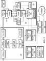
- FIG. 2 illustrates the operating environment and general system configuration of a representative refill system implementing the present invention.
- a refillable drug-pump device 200 may include a drug reservoir, a pump chamber and control circuitry for operating the device 200. Drug from the reservoir is delivered to an anatomical site via a cannula, and the reservoir may be refilled by the needle 102 of the handpiece 100 via a fill port.
- various operative components of the refill system are housed in a base unit 210, which contains a drug refill reservoir 215, a waste reservoir 217, and a reservoir 220 for rinsing fluid.
- a pumping unit 222 includes one or more pumps, e.g., one or more pneumatic air pumps, vacuum pumps, combination dual-diaphragm pumps, or any other pump configurations known in the field to create a suitable pressure differential. Further, it is well known and common practice in the medical industry to create a sterile barrier between any liquid and the pump itself by using sterile filters and an air gap. This allows the pumping unit 222 to be modular and reusable.
- the pumping unit 222 may comprise more than one pump according to the requirements of the refill process such as the number of fluids, fluidic channels, and pump-actuation requirements.
- these pumping units are regulated by software operative within an electronic control circuit 225 that includes a microprocessor.
- the clinician may opt to manually trigger the start of each phase of the refill procedure using a mechanical actuator after the previous phase has ended.
- the actuator may be built into the handpiece 100, but some buttons or switches may be located separately such as in a foot pedal.
- the pumping unit 222 may actively communicate with the device 200 through telemetry or other electronic communication methods to ensure successful refill and no accidental drug delivery during the refill process. Such communication protocols may also be used during refill to run diagnostic checks on the drug-delivery device.
- Flow rates and/or pressure readings known to be accurate may be compared to sensor readings from the device 200 to calibrate a flow sensor via a known dosing profile and/or a pressure sensor via sensed pressure fluctuations during the refill process.
- Such diagnostic and recalibration protocols improve the accuracy of drug delivery over the course of the lifetime of the device 200.
- control circuitry 225 of the base unit 210 may include a communication or telemetry module (including a transceiver and related circuitry) 230 provided separately from the control circuitry 225, e.g., in a handheld telemetry wand 232 that allows the clinician to conveniently bring the wand 232 in the vicinity of the implanted pump device 200.
- the wand may be corded to the base unit 210, or may communicate with the base unit 210 via a separate wireless connection. If employed, the wand 232 may be used to interrogate the device 200 and allows for bi-directional data exchange and/or power transfer.
- Interrogation may involve, for example, switching the device 200 to a refill mode in which the device's internal actuation (electrolysis, electroosmosis, piezo-electric actuation, etc.) is turned off, and information such as refill drug name (e.g., the ID associated with a removable drug reservoir 215 and read by a reader 238), concentration, and volume may be transmitted to the device 200.
- the interrogation step may also include an authentication protocol to prevent drug off-label use and to ensure the implant's software security.
- the data exchanged with the drug pump device 200 may be stored on a local server 240 integrated with or connected to the base unit 210.
- the communication module 230 may permit the base unit 210 to communicate with an external server 245, e.g., remotely via the Internet.
- the base unit 210 may have Wi-Fi, Zigbee, or a cellular phone chip (GSM, CDMA) that is constantly activated to cellular service or other wireless capability. This permits patient and drug data to be stored outside the refill system ("in the cloud”), and may provide further levels of security and operational flexibility.
- special eyeglasses 250 equipped with a telemetry module 252 are used to recharge the battery of the device 200; such eyeglasses are described in U.S. Serial No. 12/463,251, filed on May 8, 2009 .
- These eyeglasses 250 and the base unit 210 of the refill system may be connected to each other or to a common console, and wireless data exchange with the drug pump device 200 may occur via the eyeglasses rather than a separate telemetry wand 232.
- one or more sensors are placed strategically in the refill system for continuous monitoring and detection of phase completion.
- a pressure sensor 260 in the needle tip 102 is used primarily to detect the pressure in the drug reservoir of the device 200 and trigger the initiation and completion of each step of the refill process as described below.
- the pressure sensor 260 in combination with passive check valves may be used to fully automate the process.
- the pressure sensor 260 in the needle tip 102 may also detect improper insertion (e.g., midway through a septum) of the refill needle 102 into the fill port of the device 200.
- Pressure sensors may be deployed in the drug reservoir 215 and waste reservoir 217 to detect possible occlusions in the system, triggering shutdown of the refill process.
- a pressure sensor is located within the fluidic path between the pumping unit 222 and the reservoirs 215, 217 to detect faults such as fluidic path leaks.
- Flow sensors may be placed inline or around the fluidic paths to monitor the flow of drug refill or waste extraction.
- these flow sensors are merely structural components such as flexible flaps that have different orientations according to the fluid-flow direction and/or rate. This provides the clinician with a visual verification of flow.
- flow sensors utilize time-of-flight, thermal effects, chemical concentration, and/or pressure to provide accurate continuous flow-rate measurements, from which total volumes of wash insertion, wash extraction, and drug refill can be calculated. Other ways of metering fluid volumes delivered and extracted may be used as well.
- the refill needle 102 may contain a biosensor (also indicated at 260) to detect specific conditions such as inflammatory biomarkers, bacterial infection, etc. Additionally, if the waste reservoir 217 is separate and removable, additional tests may be performed on the extracted waste fluid using external equipment such as lab assays and a mass spectrometer.
- a representative modular unit 300 is shown in FIG. 3 .
- the modular unit 300 may include features such as windows through which waste extraction and drug refill can be visualized during the refill process.
- the waste reservoir 217 may be coated so the introduction of liquid will give the reservoir a characteristic (e.g., noxious) coloring.
- Each reservoir may also have different types of connection so that the reservoirs are not mistakenly interchanged.
- the modular unit 300 may also include structural features such as tubing management and safe needle storage, as well as slots that accommodate standard drug vials that may serve as the reservoirs (obviating the need to fill the drug reservoir 215 with a syringe).
- the modular unit 300 may be placed in the sterile field so the clinician may visually monitor the progress of the refill process through the windows. Depending on the refill requirements (refill drug volume, number of wash cycles, etc.), the modular unit 300 may be built into the handpiece 100.
- the modular unit 300 may incorporate multiple drug reservoirs.
- the modular unit 300 contains two drug reservoirs 215 and an additional mixing reservoir (not shown). Inactive drug from one drug reservoir and an activating agent from the second drug reservoir, for example, may be transferred into the mixing reservoir where the drug is activated and readied for injection.
- Other configurations incorporating a plurality of reservoirs actuated in parallel or successive steps, or in any combination, are also possible.
- electronic regulators and/or active valves may be utilized to selectively close certain fluidic paths at certain time periods.
- the modular unit 300 may also contain a heating element for warming the drug to body temperature, e.g., to reduce patient discomfort caused by the temperature difference during introduction of the drug.
- the pumping unit 222 includes a vacuum pump 410 for drawing material from the waste reservoir 217 over a fluid line 412 and a pump 415 that drives liquid drug from the drug reservoir 215 through the needle 102 via a fluid line 417.
- the pump 415 may be a standard mechanical pump (e.g., gear, diaphragm, peristaltic, etc.).
- a pair of electronic regulators 420, 422 control the operation of the pumps 410, 415, and are themselves under the control of the electronic control circuitry 225 shown in FIG. 2 .
- a pair of solenoid valves 430, 432 also under the control of the regulators 420, 422 and/or circuitry 225, allow the fluid lines 412, 417 to be vented to atmosphere.
- the fluidic arrangement also includes a pair of inline sterile filters 440, 442.
- the various illustrated components may be as desired in the handpiece 100, the base unit 210, and the modular unit 300.
- the drug reservoir 215 is filled by a syringe 450 via the two-way check valve 110 after passing through a sterile filter 453.
- FIG. 5 illustrates an alternative fluidic arrangement that includes an additional drug reservoir 215' and associated components (i.e., check valve 110', sterile filters 442', 453' and syringe 450'). These components are fluidically connected to the pump 415 over a third fluid line 417'.
- the pump 415 alternately controls flow over and venting of one of the lines 417, 417' by means of an expanded solenoid valve 432, so that drug in either of the reservoirs 215, 215' may be selectably expelled through the needle 102.
- FIG. 6 illustrates a fluidic arrangement containing a rinse reservoir 220.
- the piping is identical to that shown in FIG. 5 , with output flow from the rinse reservoir 220 under the control of the pump 415.
- the refill system may include features that minimize dead space, thereby reducing the amount of drug required for the refill process. This reduces the total cost per procedure.
- the drug refill reservoir 215 is placed in the handpiece 100 so that drug is not wasted in the tubing between the needle tip 102 and the reservoir 215. This configuration is useful in cases where the refill volume does not hinder the user's ability to hold and properly use the refill handpiece 100.
- a modular unit is placed within the sterile field, and contains the drug and waste reservoirs 215, 217, thereby reducing the fluid-containing tubing length compared to placement of the drug reservoir in the pumping unit outside of the sterile field.
- the drug refill systems described above may be used to fill, flush, or extract material from a reservoir. Techniques for using the systems will now be discussed.
- a preparation phase is conducted within the sterile field, and begins with filling a syringe 450 with medicament. Air is purged from the syringe 450, which is then connected to the refill handpiece 100 or modular unit 300 via a secure connection (e.g., a luer lock connection). The syringe contents are transferred through a sterile barrier 453, through the two-way check valve 110, and into the refill drug reservoir 215.
- the solenoid valve 432 is initially open to the atmosphere and the passive two-way check valve 110 is open to the drug reservoir. Therefore, the drug from the syringe 450 is biased only to enter the drug reservoir 215.
- This step may be repeated for any additional drug or wash solutions necessary in adjacent reservoirs 215'.
- the two-way check valves 110, 110' may have different diameters to prevent the connection of the wrong needle.
- the medicament vials may be replaceable components integrated into the modular unit 300 to obviate the need for a syringe 450.
- drug refill may be initiated by the insertion of the needle 102 into the refill port of the medical device 200.
- the refill process is started. Correct insertion may be tested by generating various pressure fluctuations and correlating the pressure changes reported by pressure sensors within the refill system and pressure sensors within the pump. Subsequent steps may be associated with specific pressure thresholds that trigger the end of the current step and the start of the subsequent step. This is illustrated in FIG. 7 (with additional reference to FIG. 6 ).
- the vacuum pump 410 is started and the solenoid valve 432 operated to open fluid communication between the pump 410 and the drug reservoir of the device 200 via the needle 102.
- the pressure in the drug reservoir (as measured in the reservoir and reported to the refill system, or as measured at the needle 102) reaches the level indicated at 702, the drug reservoir 215 is empty and aspiration is complete.
- a short interval passes and at the time indicated at 703, the valves 430, 432 are operated to open fluid communication between the pump 415 and the drug reservoir of the device 200 via the fluid line 417' (and the needle 102).
- the pressure in the receiving reservoir rises as it is filled with washing liquid from the reservoir 220, and when it reaches the level indicated at 704, the reservoir is once again full.
- the aspiration step is repeated to purge the reservoir of the washing liquid, and another washing cycle (filling followed by vacuum) is performed. After a short time interval following the end of this second washing cycle, the pressure and time reach the values indicated at 706, and the reservoir is filled with drug. That is, the valves 430, 432 are operated to open fluid communication between the pump 415 and the drug reservoir of the device 200 via the fluid line 417 (and the needle 102), and the pressure in the receiving reservoir rises as it is filled with drug from the reservoir 215. The pressure then falls to the steady-state level associated with a full reservoir and indicated at 707. As illustrated in FIG. 8 , these curve profiles (i.e., pressure-time relationships) are replicable at various fill and vacuum pressures with the basic pressure-time profile retained.
- FIG. 9 illustrates the steps of the procedure in flowchart form.
- the pressure-time profile shown in FIG. 7 may be used as a template for a normal aspiration and refill sequence.
- the refill-system controller 225 ( FIG. 2 ) may be programmed to recognize specific parameter (e.g., relative time, duration and/or pressure values, thresholds, curve responses, asymptotic line, inflection points, or other detectable curve characteristics) values and, based on these, initiate or terminate each step of the refill process.
- specific parameter e.g., relative time, duration and/or pressure values, thresholds, curve responses, asymptotic line, inflection points, or other detectable curve characteristics
- these trigger values are stored permanently in non-volatile memory (e.g., in circuitry 225) following manufacture and calibration.
- the values may be modified based on, for example, use and self-assessment by the controller, e.g., via dialog with the operator - that is, the controller may initiate a test procedure and verify proper completion of each step in conformity with the stored trigger values, modifying these values if necessary based on the results of the tests. This is especially useful in embodiments in which the control system is designed for repeated use, and values may drift over time.
- the trigger values may be one or more of a detected pressure, flow rate, cumulative flow, pressure slope change, duration of a specific pressure, the time of a change relative to a previous measured value, or plateauing within specific pressure ranges.
- the inserting, washing, and filling steps may have specific pressure thresholds that signal the end of the step within the sequence.
- wash solution or new drug is pumped via the fluid line 417, 417' containing a two-way check valve 110, 110' at a pressure greater than the pressure required to open this and any other check valves in the fluid line, or to overcome any internal pressures that may be present in the drug refill portion of the medical device 200.
- the fill pressure is maintained below a level that would compromise the integrity of the device 200 or open any check valves associated with the drug-delivery portion of the device 200.
- the fill pressure is also less than the cracking pressure of any check valves associated with the cannula, catheter, or tubing through which the medical device 200 usually pumps drug to the target tissue region. This prevents any inadvertent release of drug or wash solution to the patient.
- the wash cycle may clean not only the drug chamber but also any filtering mechanisms embedded therein (e.g., built flush with the chamber walls as part of the cannula). This prevents drug aggregate formations, debris, or other material from being released into the patient while allowing the material caught in the filter to be removed and withdrawn during the wash cycle.
- Other filter configurations including redundant filters partially built into numerous areas of the drug reservoir wall may benefit from washing as discussed herein.
- a vacuum is drawn through the fluid line 412 containing the one-way valve 112.
- the pressure in the line 412 is greater than the cracking pressure of the one-way valve 112 but is maintained below a level that would compromise the integrity of the medical device 200 or any check valves and/or tubing sets therein or fluidically connected thereto.
- This step withdraws the wash solution introduced in the previous step as well as any residual drug contained within the medical device 200.
- new drug is pumped via the fluid line 417 containing the two-way check valve 110 at a pressure greater than the pressure required to open this and any other check valves in the fluid line, or to overcome any internal pressures that may be present in the drug refill portion of the medical device 200.
- the fill pressure is maintained below a level that would compromise the integrity of the device 200 or open any check valves associated with the drug-delivery portion of the device 200.
- the fill pressure is also less than the cracking pressure of any check valves associated with the cannula, catheter, or tubing through which the medical device 200 usually pumps drug to the target tissue region. This prevents inadvertent drug release to the patient during the refill process.
- the clinician may elect to provide a dose.
- the refill pressure may be allowed to rise to overcome the cracking pressure of any check valves associated with the cannula or tubing through which the medical device 200 usually pumps drug to the target tissue region. This allows the clinician to provide a dose of the medication at the time of refill without creating another passage to the target tissue region via a syringe or another cannula. This dose is accurately measured using the refill system's metering capabilities.
- the needle 102 is removed from the refill port of the device 200.
- various portions of the refill system may be disposable.
- the entire handpiece 100 and tubing may be removed from the base unit and disposed of.
- the handpiece 100 is a portable unit with a built-in pumping mechanism, the entire unit may be disposable.
- FIG. 10 illustrates an exemplary pressure-comparison decision tree used for aspiration based on pressure readings and a target profile as shown in FIG. 7 .
- the process begins at 1000 and, in a first step 1010, a timeout timer (implemented in control circuitry 225) is activated. Following a delay of 0.25 sec, at step 1030 the outlet pressure P outlet at the tip of the needle 102 is measured and compared to the sum of the vacuum rating of the pump 410 (P VSource ), the cracking pressure of the check valve 110 (P VCheckValve ), and a tolerance value (+/-) selected to account for expected error and/or an acceptable degree of deviation.
- P VSource the vacuum rating of the pump 410
- P VCheckValve the cracking pressure of the check valve 110
- a tolerance value (+/-) selected to account for expected error and/or an acceptable degree of deviation.
- step 1030 If the compared values are not equal (step 1030), no action is taken if a timeout value has not been reached, but if sufficient time has passed (step 1040), the outlet pressure is checked to ensure it is not zero (step 1050). If not, an error is registered (step 1060); and if so, the system reports that the needle 102 has not been properly inserted into the drug refill port (step 1070). If, on the other hand, the values compared at step 1030 are equal and sufficient time has elapsed (step 1080) for complete draining of the drug chamber to have occurred, the needle must be blocked due to incorrect insertion (step 1090) which is preventing correct or complete aspiration.
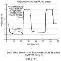
- FIG. 11 Another mode of error detection is illustrated in FIG. 11 .
- the illustrated pressure profile is similar to those depicted in FIGS. 7 and 8 , but deviates in a way that detectably indicates an error - namely, a blocked needle 102.
- the pressure plateaus briefly between points 703 and 704, and this plateau occurs when the reservoir is full. Its absence indicates that the increasing pressure is not due to a filling reservoir but to blockage at the needle 102.
- This condition is computationally detected by comparison of the profile to a template profile having the plateau; although deviations from expected values within defined limits may not indicate an error, the absence of an expected profile feature is far more likely to indicate an error condition.
- Electrolysis liquid is also preferably replaced periodically to ensure maintenance of optimal efficiency.
- Electrolysis solution may be any solution that undergoes at least a partial phase change from a liquid state to a gaseous state upon activation of electrolysis electrodes associated therein. Upon deactivation of the electrolysis electrodes, e.g., in the presence of a catalyst (such as platinum), the evolved gas redissolves in the liquid.
- the electrolysis solution may consist essentially of a saline solution, a solution comprising magnesium sulfate, sodium sulfate, or any other electrolysis formulation known in the art.
- electrolysis solution does not return to its original liquid-only volume, thereby reducing the effective volume of any adjacent drug chamber on which the electrolysis chamber is operative.
- electrolysis gases e.g. hydrogen gas, oxygen gas, etc.
- one or more electrolysis gases may permeate, resulting in a ratio of gases differing from the original. This may result in a less efficient electrolysis process, requiring greater power to create the same volume of gas and longer electrolytic gas-generation time.
- the refill system described herein may be used to refill the electrolysis chamber of a device 200.
- the handpiece 100 is used to insert the needle 102 into a refill port of the electrolysis chamber.
- the telemetry wand 232 is employed to interrogate the device 200 and facilitate bi-directional data exchange and/or power transfer.
- the communication module 230 is used to activate the electrolysis system of the device pump, either using the internal power source of device 200 or by supplying power to the device through wireless telemetry.
- the electrolysis electrodes are driven to create a predetermined amount of gas within the electrolyte chamber, and at least some of this gas is allowed to escape through the inserted needle 102 (without causing delivery of drug to the patient; the drug chamber may be emptied prior to electrolysis refill as a precaution).
- the pump 410 may be operated to create a predetermined vacuum to facilitate electrolysis gas removal and shorten gas removal time.
- the predetermined vacuum is well controlled by the refill system to prevent any damage to the device 200 by continuously monitoring and adjusting vacuum pressure.
- the refill system is used to replace the evacuated electrolysis gas with an equivalent amount of fresh electrolyte liquid.
- a rinse cycle may optionally be employed.
Landscapes
- Health & Medical Sciences (AREA)
- Life Sciences & Earth Sciences (AREA)
- Veterinary Medicine (AREA)
- Engineering & Computer Science (AREA)
- Public Health (AREA)
- General Health & Medical Sciences (AREA)
- Animal Behavior & Ethology (AREA)
- Anesthesiology (AREA)
- Hematology (AREA)
- Heart & Thoracic Surgery (AREA)
- Biomedical Technology (AREA)
- Vascular Medicine (AREA)
- Mechanical Engineering (AREA)
- Pharmacology & Pharmacy (AREA)
- Infusion, Injection, And Reservoir Apparatuses (AREA)
Description
- This application claims priority to and the benefit of
U.S. Provisional Patent Application No. 61/920,195, filed on December 23, 2013 - Medical treatment often requires the administration of a therapeutic agent (e.g., medicament, drugs, etc.) to a particular part of a patient's body. As patients live longer and are diagnosed with chronic and/or debilitating ailments, the need to place even more protein therapeutics, small-molecule drugs, and other medications into targeted anatomical areas will only increase. Some maladies, however, are difficult to treat with currently available therapies and/or require administration of drugs to difficult-to-reach anatomical regions. Many of these therapies would benefit from concentrated target-area treatment, which would reduce systemic side effects. Furthermore, certain drugs such as protein therapeutics are expensive, costing thousands of dollar per vial. For these reasons, new and improved approaches to targeted drug delivery are constantly sought.
- Implantable drug-delivery devices with refillable drug reservoirs address and overcome many of the problems associated with conventional drug-delivery modalities. They generally facilitate controlled delivery of pharmaceutical solutions to a specified target. As the contents of the drug reservoir deplete, a clinician may refill the reservoir in situ, i.e., while leaving the device implanted within the patient's body.
- As implantable devices of varying sizes, refill requirements, and implant locations become available, the refill process becomes progressively complicated. However, the refill systems themselves and the associated processes have not fundamentally improved. Current refill systems may use intricate systems of syringes, multiple three-way valves, pinch valves, etc. that are manually or electronically actuated to transition from open to closed positions throughout the refill process. These systems have a learning curve and multiple steps that are prone to human or programming error. Additionally, if refill is performed manually, improper or sub-optimal needle insertion may cause damage to the drug-delivery device, additional patient discomfort or, worse, danger to the patient.
- Therefore, ways of simplifying the procedure and reducing the number of potential errors is highly desired.
- In various embodiments, the present invention relates to refill systems incorporating a refill needle, reservoirs, a system of passive check valves of known cracking pressures, a pressure actuation pump used to refill drug pump devices, and various sensors throughout the system. By automating portions of the system, implementations of the present invention allow the clinician to concentrate on the overall refill procedure without the distractions of actuating each step of a refill sequence.
- The present invention provides, in various embodiments, a refill system for drug-delivery devices. For example, the invention may be implemented as a system for refilling an implanted, refillable drug pump device including a drug reservoir with a fill port. The system may include a needle for insertion into the fill port of the drug pump device and fluidically connectable to one or more fluid containers, one or more pumps for causing fluid flow through the needle between the fluid container(s) and the drug reservoir within the device being refilled, a plurality of check valves, electronic circuitry including a processor for controlling operation of the pump(s), and a wireless communication module facilitating wireless data exchange between the refill system and the implanted drug pump device. The system may further include tubing for fluidically connecting the fluid container(s) to the needle. This refill system may also be used to refill subcutaneous pumps that are placed externally (e.g., wearable insulin pumps and pain pumps).
- Embodiments of the present invention provide a partially to fully automated system with multiple built-in safeguards that reduce the number of steps and the subsequent total time of the refill process. Passive mechanical safeguards prevent errors, and various structural features and configurations may minimize the dead space in tubing sets, thereby reducing or eliminating drug waste during administration. In some embodiments, pressure and/or other parameters are monitored and detection of pre-set values triggers the initiation and completion of one or more (or all) steps in the refill process.
- The present invention simplifies the refill process and provides many advantages. Unlike current refill systems that use intricate systems of syringes, multiple three-way valves, pinch valves, etc. that are manually or electronically changed from open to closed positions throughout the refill process, embodiments of the present invention rely on the known pressures required throughout the refill process to partially or fully automate the refill procedure.
- Accordingly, in a first aspect, embodiments of the invention feature an apparatus for refilling a reservoir that includes or consists essentially of a plurality of reservoirs, a plurality of reservoir fluid channels, an outlet fluid channel, a plurality of valves for fluidically sealing the reservoir fluid channels and the outlet fluid channel, at least one sensor, at least one actuation mechanism, a needle, and a controller. Each of the plurality of reservoir fluid channels is associated with one of the reservoirs. The outlet fluid channel is fluidically connected to the reservoir fluid channels. Each of the plurality of valves has a cracking pressure. The at least one sensor monitors pressure in the reservoir fluid channels and the outlet fluid channel. The needle has a lumen in fluid communication with the outlet fluid channel, and the needle is configured for insertion into a drug-delivery port of an implantable medical device. The controller actuates at least one said pump and various ones of the valves in accordance with a protocol including or consisting essentially of a sequence of steps, whereby fluidic pathways are opened between different ones of the reservoirs and the needle in a washing and filling sequence, each of the steps being associated with an expected pressure level.
- Embodiments of the invention may include one or more of the following in any of a variety of combinations. The controller may be configured to execute a step in the sequence upon detection, via the sensor, of the expected pressure level. At least some of the valves may be active valves. At least some of the valves may be passive valves. The apparatus may include at least one flow sensor and/or at least one biosensor. The controller may be configured to control the pump so as to maintain a pressure through the outlet lumen below a pressure causing damage to an implantable device (e.g., an implantable medical device) connected to the needle. The controller may be configured to control the pump so as to maintain a pressure through the outlet lumen below a pressure causing an implantable device (e.g., an implantable medical device) connected to the needle to expel material. The controller may be configured to control the pump so as to maintain, during a filling or aspiration step, a pressure through the outlet lumen above a cracking pressure of check valves in the fluid lines operatively used during the filling or aspiration step. The controller may include a memory for storing a plurality of expected pressure levels and expected intervals therebetween. The controller may be configured to monitor the at least one pressure sensor and, upon detection of an expected pressure level following an expected interval, to initiate or terminate a protocol step. The apparatus may include at least one sensor for a parameter other than pressure, and the controller (i) may include a memory for storing a temporal profile of expected parameter values including pressure values and (ii) may be configured to monitor the sensors and, upon detection of a deviation from the stored profile, report an error condition. The parameter values may include or consist essentially of a detected flow rate, cumulative flow, pressure slope change, duration of a specific pressure, and/or plateauing within specific pressure ranges.
- In a second aspect, embodiments of the invention feature a method of refilling an implantable device having a drug chamber. A refill apparatus is provided. The refill apparatus includes or consists essentially of at least one pump, a plurality of reservoirs, a plurality of reservoir fluid channels each associated with one of the reservoirs, a plurality of valves, each having a cracking pressure, for fluidically sealing the reservoir fluid channels and the outlet fluid channel, an outlet fluid channel fluidically connected to the reservoir fluid channels, and a needle having a lumen in fluid communication with the outlet fluid channel. A pressure level is monitored. The needle is inserted into a drug-delivery port of the implantable device. At least one said pump and various ones of the valves are actuated in accordance with a protocol including or consisting essentially of a sequence of steps whereby fluidic pathways are opened between different ones of the reservoirs and the needle in a washing and filling sequence, each of the steps being associated with an expected pressure level.
- Embodiments of the invention may include one or more of the following in any of a variety of combinations. The washing and filling sequence may include or consist essentially of flushing a drug chamber of the implantable device by (i) causing a first fluid from a first one of the reservoirs to enter the drug chamber via the needle at a pressure not exceeding a maximum tolerable pressure, (ii) removing the first fluid from the drug chamber, and (iii) causing a drug-containing liquid to enter at a pressure not exceeding the maximum tolerable pressure. The maximum tolerable pressure may be less than a pressure causing damage to the implantable device. The maximum tolerable pressure may be less than a pressure causing flow through the implantable device. At least one parameter other than pressure may be monitored, and, upon detection of a parameter value matching a stored trigger value, a step in the sequence may be initiated or terminated. The trigger values may include or consist essentially of a detected flow rate, cumulative flow, pressure slope change, duration of a specific pressure, and/or plateauing within specific pressure ranges. At least one parameter other than and in addition to pressure may be monitored. A temporal profile of expected parameter values including pressure values may be stored. Based on the monitored parameters, an error condition may be reported upon detection of a deviation from the stored profile.
- The term "substantially" or "approximately" means ±10% (e.g., by weight or by volume), and in some embodiments, ±5%. Reference throughout this specification to "one example," "an example," "one embodiment," or "an embodiment" means that a particular feature, structure, or characteristic described in connection with the example is included in at least one example of the present technology. Thus, the occurrences of the phrases "in one example," "in an example," "one embodiment," or "an embodiment" in various places throughout this specification are not necessarily all referring to the same example. Furthermore, the particular features, structures, routines, steps, or characteristics may be combined in any suitable manner in one or more examples of the technology. The headings provided herein are for convenience only and are not intended to limit or interpret the scope or meaning of the claimed technology.
- The foregoing will be more readily understood from the following detailed description of the invention, in particular, when taken in conjunction with the drawings, in which:
-
FIG. 1A is a perspective view of a handheld refill tool in accordance with various embodiments of the invention. -
FIG. 1B is a cutaway view of the device shown inFIG. 1A . -
FIG. 2 is a block diagram of a drug pump device and refill system in accordance with various embodiments of the invention, illustrating communication links between various components of the system. -
FIG. 3 is a perspective view of a modular unit in accordance with embodiments of the invention. -
FIGS. 4-6 are piping diagrams in accordance with various embodiments of the invention. -
FIG. 7 is a graph illustrating the pressure-time profile of a representative aspiration and fill sequence. -
FIG. 8 depicts retention of the basic curve profile shown inFIG. 7 using different fill and vacuum pressures. -
FIG. 9 is a flowchart illustrating a basic decision tree for a refill cycle in accordance with embodiments of the invention. -
FIG. 10 is a flowchart illustrating the aspiration and fill sequence that generated the graph shown inFIG. 7 . -
FIG. 11 is a graph illustrating conditions indicative of a blocked needle. - The present invention relates, generally, to refill systems for implantable drug pump devices with refillable drug reservoirs, e.g., ocular drug pumps, implantable insulin pumps, inner ear pumps, and brain pumps. With reference to
FIGS. 1A and 1B , the refill system may be implemented in multiple components, one of which is ahandpiece 100. As described in greater detail below, the pumps, control circuitry, and some of the valves and sensors are integrated into a reusable base unit, a pair of fluid channels from which enter the distal end thehandpiece 100; the handpiece terminates in a detachable (and replaceable)refill needle 102, which is preferably a small-bore needle. Thehandpiece 100 includes anergonomic handle portion 105 that allows a clinician to refill the implanted device in situ. In preferred embodiments, thesame needle 102 is used during the entire refill process so as to minimize the needle insertion frequency into the drug reservoir and the associated stress for patient and clinician, as well as the wear on the refill port. A single needle insertion may suffice even if multiple fluids (e.g., multiple separately stored drugs to be administered together) are to be injected into the drug pump device as explained below. Theneedle 102 is, thus, sequentially connected to different fluid containers. - The
handpiece 100 is desirably weight-balanced and may have built-in transparent windows so fluid movement can be visually confirmed. For safety purposes, thehandpiece 100 may have a built-in, user-actuated retractable needle-storage slot to conceal and store theneedle 102 when the refill tool is not in use. In certain embodiments, as best seen in the cutaway view ofFIG. 1B , thehandpiece 100 may contain a pair ofcheck valves drug reservoir 115. Either or bothcheck valves valve 110 is a two-way check valve and thevalve 112 is a one-way check valve. Thevalves fluid lines handpiece 100 may also contain one or more modalities to assist in detecting the refill port of the device to be refilled. Such modalities may include a pressure sensor, a light source, a capacitive sensing or piezo-element tip, and/or a magnetic or Hall effect structure, which may provide the user with additional feedback throughout the refill process. -
FIG. 2 illustrates the operating environment and general system configuration of a representative refill system implementing the present invention. As described, for example, inU.S. Serial No. 13/632,722 , a refillable drug-pump device 200 may include a drug reservoir, a pump chamber and control circuitry for operating thedevice 200. Drug from the reservoir is delivered to an anatomical site via a cannula, and the reservoir may be refilled by theneedle 102 of thehandpiece 100 via a fill port. As described below, various operative components of the refill system are housed in abase unit 210, which contains adrug refill reservoir 215, awaste reservoir 217, and areservoir 220 for rinsing fluid. Apumping unit 222 includes one or more pumps, e.g., one or more pneumatic air pumps, vacuum pumps, combination dual-diaphragm pumps, or any other pump configurations known in the field to create a suitable pressure differential. Further, it is well known and common practice in the medical industry to create a sterile barrier between any liquid and the pump itself by using sterile filters and an air gap. This allows thepumping unit 222 to be modular and reusable. Thepumping unit 222 may comprise more than one pump according to the requirements of the refill process such as the number of fluids, fluidic channels, and pump-actuation requirements. - In various embodiments, these pumping units are regulated by software operative within an
electronic control circuit 225 that includes a microprocessor. However, the clinician may opt to manually trigger the start of each phase of the refill procedure using a mechanical actuator after the previous phase has ended. The actuator may be built into thehandpiece 100, but some buttons or switches may be located separately such as in a foot pedal. If the drug-delivery device contains one or more sensors (flow, pressure, biologic, etc.), thepumping unit 222 may actively communicate with thedevice 200 through telemetry or other electronic communication methods to ensure successful refill and no accidental drug delivery during the refill process. Such communication protocols may also be used during refill to run diagnostic checks on the drug-delivery device. Flow rates and/or pressure readings known to be accurate may be compared to sensor readings from thedevice 200 to calibrate a flow sensor via a known dosing profile and/or a pressure sensor via sensed pressure fluctuations during the refill process. Such diagnostic and recalibration protocols improve the accuracy of drug delivery over the course of the lifetime of thedevice 200. - Thus, the
control circuitry 225 of thebase unit 210 may include a communication or telemetry module (including a transceiver and related circuitry) 230 provided separately from thecontrol circuitry 225, e.g., in ahandheld telemetry wand 232 that allows the clinician to conveniently bring thewand 232 in the vicinity of the implantedpump device 200. The wand may be corded to thebase unit 210, or may communicate with thebase unit 210 via a separate wireless connection. If employed, thewand 232 may be used to interrogate thedevice 200 and allows for bi-directional data exchange and/or power transfer. Interrogation may involve, for example, switching thedevice 200 to a refill mode in which the device's internal actuation (electrolysis, electroosmosis, piezo-electric actuation, etc.) is turned off, and information such as refill drug name (e.g., the ID associated with aremovable drug reservoir 215 and read by a reader 238), concentration, and volume may be transmitted to thedevice 200. The interrogation step may also include an authentication protocol to prevent drug off-label use and to ensure the implant's software security. - The data exchanged with the
drug pump device 200 may be stored on alocal server 240 integrated with or connected to thebase unit 210. Alternatively, thecommunication module 230 may permit thebase unit 210 to communicate with anexternal server 245, e.g., remotely via the Internet. For example, thebase unit 210 may have Wi-Fi, Zigbee, or a cellular phone chip (GSM, CDMA) that is constantly activated to cellular service or other wireless capability. This permits patient and drug data to be stored outside the refill system ("in the cloud"), and may provide further levels of security and operational flexibility. - In some embodiments,
special eyeglasses 250 equipped with atelemetry module 252 are used to recharge the battery of thedevice 200; such eyeglasses are described inU.S. Serial No. 12/463,251, filed on May 8, 2009 eyeglasses 250 and thebase unit 210 of the refill system may be connected to each other or to a common console, and wireless data exchange with thedrug pump device 200 may occur via the eyeglasses rather than aseparate telemetry wand 232. - In some embodiments, one or more sensors are placed strategically in the refill system for continuous monitoring and detection of phase completion. In one embodiment, a
pressure sensor 260 in theneedle tip 102 is used primarily to detect the pressure in the drug reservoir of thedevice 200 and trigger the initiation and completion of each step of the refill process as described below. Thepressure sensor 260 in combination with passive check valves may be used to fully automate the process. Thepressure sensor 260 in theneedle tip 102 may also detect improper insertion (e.g., midway through a septum) of therefill needle 102 into the fill port of thedevice 200. Pressure sensors may be deployed in thedrug reservoir 215 andwaste reservoir 217 to detect possible occlusions in the system, triggering shutdown of the refill process. In some embodiments, a pressure sensor is located within the fluidic path between thepumping unit 222 and thereservoirs - Flow sensors may be placed inline or around the fluidic paths to monitor the flow of drug refill or waste extraction. In some implementations, these flow sensors are merely structural components such as flexible flaps that have different orientations according to the fluid-flow direction and/or rate. This provides the clinician with a visual verification of flow. In other embodiments, flow sensors utilize time-of-flight, thermal effects, chemical concentration, and/or pressure to provide accurate continuous flow-rate measurements, from which total volumes of wash insertion, wash extraction, and drug refill can be calculated. Other ways of metering fluid volumes delivered and extracted may be used as well.
- Implantable devices are vulnerable to tissue ingrowth and possible infection. Accordingly, the
refill needle 102 may contain a biosensor (also indicated at 260) to detect specific conditions such as inflammatory biomarkers, bacterial infection, etc. Additionally, if thewaste reservoir 217 is separate and removable, additional tests may be performed on the extracted waste fluid using external equipment such as lab assays and a mass spectrometer. - A representative
modular unit 300 is shown inFIG. 3 . Besides the reservoirs, themodular unit 300 may include features such as windows through which waste extraction and drug refill can be visualized during the refill process. Thewaste reservoir 217 may be coated so the introduction of liquid will give the reservoir a characteristic (e.g., noxious) coloring. Each reservoir may also have different types of connection so that the reservoirs are not mistakenly interchanged. Themodular unit 300 may also include structural features such as tubing management and safe needle storage, as well as slots that accommodate standard drug vials that may serve as the reservoirs (obviating the need to fill thedrug reservoir 215 with a syringe). Themodular unit 300 may be placed in the sterile field so the clinician may visually monitor the progress of the refill process through the windows. Depending on the refill requirements (refill drug volume, number of wash cycles, etc.), themodular unit 300 may be built into thehandpiece 100. - The
modular unit 300 may incorporate multiple drug reservoirs. In one embodiment, themodular unit 300 contains twodrug reservoirs 215 and an additional mixing reservoir (not shown). Inactive drug from one drug reservoir and an activating agent from the second drug reservoir, for example, may be transferred into the mixing reservoir where the drug is activated and readied for injection. Other configurations incorporating a plurality of reservoirs actuated in parallel or successive steps, or in any combination, are also possible. In some such embodiments, electronic regulators and/or active valves may be utilized to selectively close certain fluidic paths at certain time periods. Themodular unit 300 may also contain a heating element for warming the drug to body temperature, e.g., to reduce patient discomfort caused by the temperature difference during introduction of the drug. - Representative fluidic arrangements for refill systems in accordance herewith are shown in
FIGS. 4-6 . In the embodiment depicted inFIG. 4 , thepumping unit 222 includes avacuum pump 410 for drawing material from thewaste reservoir 217 over afluid line 412 and apump 415 that drives liquid drug from thedrug reservoir 215 through theneedle 102 via afluid line 417. Thepump 415 may be a standard mechanical pump (e.g., gear, diaphragm, peristaltic, etc.). A pair ofelectronic regulators pumps electronic control circuitry 225 shown inFIG. 2 . A pair ofsolenoid valves regulators circuitry 225, allow thefluid lines sterile filters handpiece 100, thebase unit 210, and themodular unit 300. Thedrug reservoir 215 is filled by asyringe 450 via the two-way check valve 110 after passing through asterile filter 453. -
FIG. 5 illustrates an alternative fluidic arrangement that includes anadditional drug reservoir 215' and associated components (i.e., check valve 110',sterile filters 442', 453' and syringe 450'). These components are fluidically connected to thepump 415 over athird fluid line 417'. Thepump 415 alternately controls flow over and venting of one of thelines solenoid valve 432, so that drug in either of thereservoirs needle 102. -
FIG. 6 illustrates a fluidic arrangement containing a rinsereservoir 220. The piping is identical to that shown inFIG. 5 , with output flow from the rinsereservoir 220 under the control of thepump 415. - The refill system may include features that minimize dead space, thereby reducing the amount of drug required for the refill process. This reduces the total cost per procedure. In one embodiment, the
drug refill reservoir 215 is placed in thehandpiece 100 so that drug is not wasted in the tubing between theneedle tip 102 and thereservoir 215. This configuration is useful in cases where the refill volume does not hinder the user's ability to hold and properly use therefill handpiece 100. In another configuration, a modular unit is placed within the sterile field, and contains the drug andwaste reservoirs - The drug refill systems described above may be used to fill, flush, or extract material from a reservoir. Techniques for using the systems will now be discussed.
- With reference to
FIGS. 4-6 , a preparation phase is conducted within the sterile field, and begins with filling asyringe 450 with medicament. Air is purged from thesyringe 450, which is then connected to therefill handpiece 100 ormodular unit 300 via a secure connection (e.g., a luer lock connection). The syringe contents are transferred through asterile barrier 453, through the two-way check valve 110, and into therefill drug reservoir 215. Thesolenoid valve 432 is initially open to the atmosphere and the passive two-way check valve 110 is open to the drug reservoir. Therefore, the drug from thesyringe 450 is biased only to enter thedrug reservoir 215. This step may be repeated for any additional drug or wash solutions necessary inadjacent reservoirs 215'. The two-way check valves 110, 110' may have different diameters to prevent the connection of the wrong needle. Alternatively, the medicament vials may be replaceable components integrated into themodular unit 300 to obviate the need for asyringe 450. - With reference to
FIG. 2 , drug refill may be initiated by the insertion of theneedle 102 into the refill port of themedical device 200. Upon confirmation of proper insertion through the septum of the refill port to achieve a fluidic connection to the drug reservoir of the device 200 (as confirmed visually and/or by pressure readings obtained with a pressure sensor), the refill process is started. Correct insertion may be tested by generating various pressure fluctuations and correlating the pressure changes reported by pressure sensors within the refill system and pressure sensors within the pump. Subsequent steps may be associated with specific pressure thresholds that trigger the end of the current step and the start of the subsequent step. This is illustrated inFIG. 7 (with additional reference toFIG. 6 ). At an initial time t0, with the system pressure at the steady-state level associated with a full or partially full reservoir and indicated at 701, thevacuum pump 410 is started and thesolenoid valve 432 operated to open fluid communication between thepump 410 and the drug reservoir of thedevice 200 via theneedle 102. When the pressure in the drug reservoir (as measured in the reservoir and reported to the refill system, or as measured at the needle 102) reaches the level indicated at 702, thedrug reservoir 215 is empty and aspiration is complete. A short interval passes and at the time indicated at 703, thevalves pump 415 and the drug reservoir of thedevice 200 via thefluid line 417' (and the needle 102). The pressure in the receiving reservoir rises as it is filled with washing liquid from thereservoir 220, and when it reaches the level indicated at 704, the reservoir is once again full. The aspiration step is repeated to purge the reservoir of the washing liquid, and another washing cycle (filling followed by vacuum) is performed. After a short time interval following the end of this second washing cycle, the pressure and time reach the values indicated at 706, and the reservoir is filled with drug. That is, thevalves pump 415 and the drug reservoir of thedevice 200 via the fluid line 417 (and the needle 102), and the pressure in the receiving reservoir rises as it is filled with drug from thereservoir 215. The pressure then falls to the steady-state level associated with a full reservoir and indicated at 707. As illustrated inFIG. 8 , these curve profiles (i.e., pressure-time relationships) are replicable at various fill and vacuum pressures with the basic pressure-time profile retained.FIG. 9 illustrates the steps of the procedure in flowchart form. - Accordingly, the pressure-time profile shown in
FIG. 7 may be used as a template for a normal aspiration and refill sequence. The refill-system controller 225 (FIG. 2 ) may be programmed to recognize specific parameter (e.g., relative time, duration and/or pressure values, thresholds, curve responses, asymptotic line, inflection points, or other detectable curve characteristics) values and, based on these, initiate or terminate each step of the refill process. In some embodiments, these trigger values are stored permanently in non-volatile memory (e.g., in circuitry 225) following manufacture and calibration. In other embodiments, the values may be modified based on, for example, use and self-assessment by the controller, e.g., via dialog with the operator - that is, the controller may initiate a test procedure and verify proper completion of each step in conformity with the stored trigger values, modifying these values if necessary based on the results of the tests. This is especially useful in embodiments in which the control system is designed for repeated use, and values may drift over time. - The trigger values may be one or more of a detected pressure, flow rate, cumulative flow, pressure slope change, duration of a specific pressure, the time of a change relative to a previous measured value, or plateauing within specific pressure ranges. For example, the inserting, washing, and filling steps may have specific pressure thresholds that signal the end of the step within the sequence.
- With reference to
FIG. 6 , wash solution or new drug is pumped via thefluid line way check valve 110, 110' at a pressure greater than the pressure required to open this and any other check valves in the fluid line, or to overcome any internal pressures that may be present in the drug refill portion of themedical device 200. The fill pressure is maintained below a level that would compromise the integrity of thedevice 200 or open any check valves associated with the drug-delivery portion of thedevice 200. The fill pressure is also less than the cracking pressure of any check valves associated with the cannula, catheter, or tubing through which themedical device 200 usually pumps drug to the target tissue region. This prevents any inadvertent release of drug or wash solution to the patient. The wash cycle may clean not only the drug chamber but also any filtering mechanisms embedded therein (e.g., built flush with the chamber walls as part of the cannula). This prevents drug aggregate formations, debris, or other material from being released into the patient while allowing the material caught in the filter to be removed and withdrawn during the wash cycle. Other filter configurations including redundant filters partially built into numerous areas of the drug reservoir wall may benefit from washing as discussed herein. - When the drug chamber of the
device 200 has been filled with wash solution, a vacuum is drawn through thefluid line 412 containing the one-way valve 112. The pressure in theline 412 is greater than the cracking pressure of the one-way valve 112 but is maintained below a level that would compromise the integrity of themedical device 200 or any check valves and/or tubing sets therein or fluidically connected thereto. This step withdraws the wash solution introduced in the previous step as well as any residual drug contained within themedical device 200. - During the fill cycle, new drug is pumped via the
fluid line 417 containing the two-way check valve 110 at a pressure greater than the pressure required to open this and any other check valves in the fluid line, or to overcome any internal pressures that may be present in the drug refill portion of themedical device 200. The fill pressure is maintained below a level that would compromise the integrity of thedevice 200 or open any check valves associated with the drug-delivery portion of thedevice 200. The fill pressure is also less than the cracking pressure of any check valves associated with the cannula, catheter, or tubing through which themedical device 200 usually pumps drug to the target tissue region. This prevents inadvertent drug release to the patient during the refill process. However, upon filling the drug reservoir, the clinician may elect to provide a dose. To conserve battery power and drug reservoir space, at the clinician's discretion, the refill pressure may be allowed to rise to overcome the cracking pressure of any check valves associated with the cannula or tubing through which themedical device 200 usually pumps drug to the target tissue region. This allows the clinician to provide a dose of the medication at the time of refill without creating another passage to the target tissue region via a syringe or another cannula. This dose is accurately measured using the refill system's metering capabilities. - When refill is complete, the
needle 102 is removed from the refill port of thedevice 200. Depending on the embodiment, various portions of the refill system may be disposable. In a tethered version, theentire handpiece 100 and tubing may be removed from the base unit and disposed of. Alternatively, if thehandpiece 100 is a portable unit with a built-in pumping mechanism, the entire unit may be disposable. -
FIG. 10 illustrates an exemplary pressure-comparison decision tree used for aspiration based on pressure readings and a target profile as shown inFIG. 7 . The process begins at 1000 and, in afirst step 1010, a timeout timer (implemented in control circuitry 225) is activated. Following a delay of 0.25 sec, atstep 1030 the outlet pressure Poutlet at the tip of theneedle 102 is measured and compared to the sum of the vacuum rating of the pump 410 (PVSource), the cracking pressure of the check valve 110 (PVCheckValve), and a tolerance value (+/-) selected to account for expected error and/or an acceptable degree of deviation. If the compared values are not equal (step 1030), no action is taken if a timeout value has not been reached, but if sufficient time has passed (step 1040), the outlet pressure is checked to ensure it is not zero (step 1050). If not, an error is registered (step 1060); and if so, the system reports that theneedle 102 has not been properly inserted into the drug refill port (step 1070). If, on the other hand, the values compared atstep 1030 are equal and sufficient time has elapsed (step 1080) for complete draining of the drug chamber to have occurred, the needle must be blocked due to incorrect insertion (step 1090) which is preventing correct or complete aspiration. But if the values are equal prior to the timeout timer having elapsed, there is a change in Poutlet signaling the completion of the aspiration process. The net result of the decision tree is verification of proper traversal of the points 701-703 inFIG. 7 . Similar decision trees are used for subsequent steps of the refill process. - Another mode of error detection is illustrated in
FIG. 11 . The illustrated pressure profile is similar to those depicted inFIGS. 7 and 8 , but deviates in a way that detectably indicates an error - namely, a blockedneedle 102. In the normal profile shown inFIG. 7 , the pressure plateaus briefly betweenpoints needle 102. This condition is computationally detected by comparison of the profile to a template profile having the plateau; although deviations from expected values within defined limits may not indicate an error, the absence of an expected profile feature is far more likely to indicate an error condition. - In drug pump embodiments utilizing an electrolysis actuation mechanism, the electrolysis liquid is also preferably replaced periodically to ensure maintenance of optimal efficiency. Electrolysis solution may be any solution that undergoes at least a partial phase change from a liquid state to a gaseous state upon activation of electrolysis electrodes associated therein. Upon deactivation of the electrolysis electrodes, e.g., in the presence of a catalyst (such as platinum), the evolved gas redissolves in the liquid. The electrolysis solution may consist essentially of a saline solution, a solution comprising magnesium sulfate, sodium sulfate, or any other electrolysis formulation known in the art.
- After repeated cycles of electrolysis and recombination, the recombination may become incomplete with some gas not redissolving. As a result, the electrolysis solution does not return to its original liquid-only volume, thereby reducing the effective volume of any adjacent drug chamber on which the electrolysis chamber is operative. Furthermore, one or more electrolysis gases (e.g. hydrogen gas, oxygen gas, etc.) may permeate, resulting in a ratio of gases differing from the original. This may result in a less efficient electrolysis process, requiring greater power to create the same volume of gas and longer electrolytic gas-generation time.
- In various embodiments, the refill system described herein may be used to refill the electrolysis chamber of a
device 200. With reference toFIG. 2 , thehandpiece 100 is used to insert theneedle 102 into a refill port of the electrolysis chamber. Next, thetelemetry wand 232 is employed to interrogate thedevice 200 and facilitate bi-directional data exchange and/or power transfer. Thecommunication module 230 is used to activate the electrolysis system of the device pump, either using the internal power source ofdevice 200 or by supplying power to the device through wireless telemetry. The electrolysis electrodes are driven to create a predetermined amount of gas within the electrolyte chamber, and at least some of this gas is allowed to escape through the inserted needle 102 (without causing delivery of drug to the patient; the drug chamber may be emptied prior to electrolysis refill as a precaution). For example, thepump 410 may be operated to create a predetermined vacuum to facilitate electrolysis gas removal and shorten gas removal time. The predetermined vacuum is well controlled by the refill system to prevent any damage to thedevice 200 by continuously monitoring and adjusting vacuum pressure. Continued proper operation and correct insertion of theneedle 102 may be continuously or intermittently tested by generating various pressure fluctuations and correlating the pressure changes obtained from pressure sensors within the refill system and the pressure sensors within the electrolysis chamber of thedevice 200. Finally, the refill system is used to replace the evacuated electrolysis gas with an equivalent amount of fresh electrolyte liquid. A rinse cycle may optionally be employed. - Having described certain embodiments of the invention, it will be apparent to those of ordinary skill in the art that other embodiments incorporating the concepts disclosed herein may be used without departing from the scope of the invention. For example, various features described with respect to one particular device type and configuration may be implemented in other types of devices and alternative device configurations as well. Accordingly, the described embodiments are to be considered in all respects as only illustrative and not restrictive.
Claims (10)
- Apparatus for refilling an implantable device having a drug chamber, the apparatus comprising:a plurality of reservoirs (215, 217, 220);a plurality of reservoir fluid channels each associated with one of the reservoirs;an outlet fluid channel fluidically connected to the reservoir fluid channels;a plurality of valves (110, 112), each having a cracking pressure, for fluidically sealing the reservoir fluid channels and the outlet fluid channel;at least one sensor (260) for monitoring pressure in the reservoir fluid channels and the outlet fluid channel;at least one actuation mechanism;a needle (102) having a lumen in fluid communication with the outlet fluid channel, the needle being configured for insertion into a drug-delivery port of an implantable medical device; characterised in that,it further comprisesa controller (225) configured to actuate at least one pump (222) and various ones of the valves (110, 112) in accordance with a protocol comprising a sequence of steps whereby fluidic pathways are opened between different ones of the reservoirs and the needle in a washing and filling sequence, each of the steps being associated with an expected pressure level.
- The apparatus of claim 1, wherein the controller (225) is configured to execute a step in the sequence upon detection, via the sensor, of the expected pressure level.
- The apparatus of claim 1, wherein at least some of the valves (110, 112) are active valves and/or passive valves.
- The apparatus of claim 1, further comprising at least one flow sensor and/or at least one biosensor.
- The apparatus of claim 1, wherein the controller (225) is configured to control the pump (222) so as to maintain a pressure through the outlet lumen below a pressure causing damage to an implantable device connected to the needle (102).
- The apparatus of claim 1, wherein the controller (225) is configured to control the pump (222) so as to maintain a pressure through the outlet lumen below a pressure causing an implantable device connected to the needle (102) to expel material.
- The apparatus of claim 5, wherein the controller (225) is configured to control the pump (222) so as to maintain, during a filling or aspiration step, a pressure through the outlet lumen above a cracking pressure of check valves in the fluid lines operatively used during the filling or aspiration step.
- The apparatus of claim 1, wherein the controller (225) (i) comprises a memory for storing a plurality of expected pressure levels and expected intervals therebetween and (ii) is configured to monitor the at least one pressure sensor (260) and, upon detection of an expected pressure level following an expected interval, to initiate or terminate a protocol step.
- The apparatus of claim 1 further comprising at least one sensor for a parameter other than pressure, wherein the controller (i) comprises a memory for storing a temporal profile of expected parameter values including pressure values and (ii) is configured to monitor the sensors and, upon detection of a deviation from the stored profile, report an error condition.
- The apparatus of claim 9, wherein the parameter values comprise at least one of a detected flow rate, cumulative flow, pressure slope change, duration of a specific pressure, or plateauing within specific pressure ranges.
Applications Claiming Priority (2)
| Application Number | Priority Date | Filing Date | Title |
|---|---|---|---|
| US201361920195P | 2013-12-23 | 2013-12-23 | |
| PCT/US2014/071917 WO2015100248A1 (en) | 2013-12-23 | 2014-12-22 | Drug refill applicator system and method of use |
Publications (3)
| Publication Number | Publication Date |
|---|---|
| EP3086827A1 EP3086827A1 (en) | 2016-11-02 |
| EP3086827A4 EP3086827A4 (en) | 2017-08-23 |
| EP3086827B1 true EP3086827B1 (en) | 2021-03-17 |
Family
ID=53398880
Family Applications (1)
| Application Number | Title | Priority Date | Filing Date |
|---|---|---|---|
| EP14875083.9A Active EP3086827B1 (en) | 2013-12-23 | 2014-12-22 | Drug refill applicator system and method of use |
Country Status (8)
| Country | Link |
|---|---|
| US (1) | US10369079B2 (en) |
| EP (1) | EP3086827B1 (en) |
| JP (1) | JP6768510B2 (en) |
| CN (1) | CN106456871B (en) |
| AU (1) | AU2014370041B2 (en) |
| CA (1) | CA2930910A1 (en) |
| ES (1) | ES2874255T3 (en) |
| WO (1) | WO2015100248A1 (en) |
Families Citing this family (12)
| Publication number | Priority date | Publication date | Assignee | Title |
|---|---|---|---|---|
| US11511035B2 (en) | 2016-07-28 | 2022-11-29 | Cerebral Therapeutics, Inc. | Implantable intraventricular sampling and infusion access device |
| US20190151239A1 (en) | 2016-07-28 | 2019-05-23 | Cerebral Therapeutics LLC | Infusing drug solution directly into brain fluid |
| US10814062B2 (en) | 2017-08-31 | 2020-10-27 | Becton, Dickinson And Company | Reservoir with low volume sensor |
| WO2019084036A1 (en) * | 2017-10-23 | 2019-05-02 | Cerebral Therapeutics LLC | Syringe for delivering medications to implanted drug delivery systems and methods for use thereof |
| CN107998488A (en) * | 2017-11-28 | 2018-05-08 | 广东嘉博制药有限公司 | A kind of infusion system of Clevidipine butyrate fat emulsion injection |
| US10973739B2 (en) * | 2018-08-23 | 2021-04-13 | ART MEDICAL Ltd. | Medical pump |
| CN109999272B (en) * | 2019-04-28 | 2021-03-23 | 甘甘医疗科技江苏有限公司 | A disposable adjustable injection device for insulin injection |
| US12551669B2 (en) | 2020-07-15 | 2026-02-17 | Biogen Ma Inc. | Medical system including two access ports |
| IL299904B1 (en) | 2020-07-20 | 2026-05-01 | Cerebral Therapeutics Inc | Fluid catheter device for recording brain state |
| JP2023547735A (en) * | 2020-11-05 | 2023-11-13 | ルナ ヘルス、インコーポレイテッド | drug delivery device |
| US12605537B2 (en) | 2022-02-15 | 2026-04-21 | Biogen Ma Inc. | Implantable medical device for use with or having recording electrode |
| CN114306799B (en) * | 2022-03-10 | 2022-07-12 | 济南鑫贝西生物技术有限公司 | Horizontal flow clean bench that dispenses |
Family Cites Families (14)
| Publication number | Priority date | Publication date | Assignee | Title |
|---|---|---|---|---|
| US7473244B2 (en) * | 2000-06-02 | 2009-01-06 | The University Of Utah Research Foundation | Active needle devices with integrated functionality |
| US20020040208A1 (en) * | 2000-10-04 | 2002-04-04 | Flaherty J. Christopher | Data collection assembly for patient infusion system |
| EP1339312B1 (en) | 2000-10-10 | 2006-01-04 | Microchips, Inc. | Microchip reservoir devices using wireless transmission of power and data |
| JP2004538042A (en) * | 2000-12-14 | 2004-12-24 | コントロール・デリバリー・システムズ | Implantable and refillable controlled release drug delivery device with port |
| US6511413B2 (en) * | 2001-05-16 | 2003-01-28 | Levram Medical Devices, Ltd. | Single cannula ventricular-assist method and apparatus |
| GB2389791B (en) | 2002-04-30 | 2006-12-13 | Steven Gill | Implantable drug delivery pump |
| GB0603037D0 (en) * | 2006-02-15 | 2006-03-29 | Renishaw Plc | Implantable fluid distribution device and a method of drug delivery |
| US8267905B2 (en) * | 2006-05-01 | 2012-09-18 | Neurosystec Corporation | Apparatus and method for delivery of therapeutic and other types of agents |
| WO2009041826A1 (en) * | 2007-09-28 | 2009-04-02 | Robert Stephen Murphy | Infusion pump mechanism |
| US8313467B2 (en) * | 2007-12-27 | 2012-11-20 | Medtronic Minimed, Inc. | Reservoir pressure equalization systems and methods |
| MX2010012212A (en) * | 2008-05-08 | 2011-09-27 | Minipumps Llc | Implantable drug-delivery devices, and apparatus and methods for filling the devices. |
| US9162024B2 (en) * | 2008-05-08 | 2015-10-20 | Minipumps, Llc | Drug-delivery pumps and methods of manufacture |
| US10286146B2 (en) * | 2011-03-14 | 2019-05-14 | Minipumps, Llc | Implantable drug pumps and refill devices therefor |
| RU2605805C2 (en) * | 2011-03-14 | 2016-12-27 | МИНИПАМПЗ, ЭлЭлСи | Device and methods for filling implanted drug pump |
-
2014
- 2014-12-22 ES ES14875083T patent/ES2874255T3/en active Active
- 2014-12-22 AU AU2014370041A patent/AU2014370041B2/en active Active
- 2014-12-22 JP JP2016539292A patent/JP6768510B2/en active Active
- 2014-12-22 CN CN201480070324.0A patent/CN106456871B/en active Active
- 2014-12-22 CA CA2930910A patent/CA2930910A1/en not_active Abandoned
- 2014-12-22 WO PCT/US2014/071917 patent/WO2015100248A1/en not_active Ceased
- 2014-12-22 EP EP14875083.9A patent/EP3086827B1/en active Active
- 2014-12-22 US US14/579,231 patent/US10369079B2/en active Active
Non-Patent Citations (1)
| Title |
|---|
| None * |
Also Published As
| Publication number | Publication date |
|---|---|
| JP6768510B2 (en) | 2020-10-14 |
| JP2017500118A (en) | 2017-01-05 |
| US10369079B2 (en) | 2019-08-06 |
| CN106456871A (en) | 2017-02-22 |
| CA2930910A1 (en) | 2015-07-02 |
| US20160374901A9 (en) | 2016-12-29 |
| AU2014370041B2 (en) | 2019-07-25 |
| AU2014370041A1 (en) | 2016-06-02 |
| CN106456871B (en) | 2020-05-26 |
| WO2015100248A1 (en) | 2015-07-02 |
| EP3086827A4 (en) | 2017-08-23 |
| EP3086827A1 (en) | 2016-11-02 |
| US20150174007A1 (en) | 2015-06-25 |
| ES2874255T3 (en) | 2021-11-04 |
Similar Documents
| Publication | Publication Date | Title |
|---|---|---|
| US10369079B2 (en) | Drug refill applicator system and method of use | |
| TWI907805B (en) | Systems and methods for substantially continuous intravenous infusion of the same or substantially the same medical fluid with fluid source replacements | |
| EP2320972B1 (en) | Implantable drug-delivery devices | |
| US10286146B2 (en) | Implantable drug pumps and refill devices therefor | |
| US9603997B2 (en) | Implantable drug pumps and refill devices therefor | |
| US9919099B2 (en) | Implantable drug pumps and refill devices therefor | |
| CN103608054B (en) | Apparatus and methods for filling implantable drug pumps | |
| EP2760504B1 (en) | Implantable drug pumps and refill devices therefor |
Legal Events
| Date | Code | Title | Description |
|---|---|---|---|
| PUAI | Public reference made under article 153(3) epc to a published international application that has entered the european phase |
Free format text: ORIGINAL CODE: 0009012 |
|
| 17P | Request for examination filed |
Effective date: 20160512 |
|
| AK | Designated contracting states |
Kind code of ref document: A1 Designated state(s): AL AT BE BG CH CY CZ DE DK EE ES FI FR GB GR HR HU IE IS IT LI LT LU LV MC MK MT NL NO PL PT RO RS SE SI SK SM TR |
|
| AX | Request for extension of the european patent |
Extension state: BA ME |
|
| DAX | Request for extension of the european patent (deleted) | ||
| A4 | Supplementary search report drawn up and despatched |
Effective date: 20170721 |
|
| RIC1 | Information provided on ipc code assigned before grant |
Ipc: A61J 1/22 20060101ALI20170717BHEP Ipc: A61M 5/14 20060101AFI20170717BHEP Ipc: A61M 5/142 20060101ALI20170717BHEP Ipc: B65B 3/00 20060101ALI20170717BHEP Ipc: A61M 5/20 20060101ALI20170717BHEP |
|
| STAA | Information on the status of an ep patent application or granted ep patent |
Free format text: STATUS: EXAMINATION IS IN PROGRESS |
|
| 17Q | First examination report despatched |
Effective date: 20190531 |
|
| GRAP | Despatch of communication of intention to grant a patent |
Free format text: ORIGINAL CODE: EPIDOSNIGR1 |
|
| STAA | Information on the status of an ep patent application or granted ep patent |
Free format text: STATUS: GRANT OF PATENT IS INTENDED |
|
| INTG | Intention to grant announced |
Effective date: 20201008 |
|
| GRAS | Grant fee paid |
Free format text: ORIGINAL CODE: EPIDOSNIGR3 |
|
| GRAA | (expected) grant |
Free format text: ORIGINAL CODE: 0009210 |
|
| STAA | Information on the status of an ep patent application or granted ep patent |
Free format text: STATUS: THE PATENT HAS BEEN GRANTED |
|
| AK | Designated contracting states |
Kind code of ref document: B1 Designated state(s): AL AT BE BG CH CY CZ DE DK EE ES FI FR GB GR HR HU IE IS IT LI LT LU LV MC MK MT NL NO PL PT RO RS SE SI SK SM TR |
|
| REG | Reference to a national code |
Ref country code: GB Ref legal event code: FG4D |
|
| REG | Reference to a national code |
Ref country code: CH Ref legal event code: EP |
|
| REG | Reference to a national code |
Ref country code: DE Ref legal event code: R096 Ref document number: 602014075851 Country of ref document: DE |
|
| REG | Reference to a national code |
Ref country code: IE Ref legal event code: FG4D |
|
| REG | Reference to a national code |
Ref country code: AT Ref legal event code: REF Ref document number: 1371649 Country of ref document: AT Kind code of ref document: T Effective date: 20210415 |
|
| REG | Reference to a national code |
Ref country code: NL Ref legal event code: FP |
|
| REG | Reference to a national code |
Ref country code: LT Ref legal event code: MG9D |
|
| PG25 | Lapsed in a contracting state [announced via postgrant information from national office to epo] |
Ref country code: NO Free format text: LAPSE BECAUSE OF FAILURE TO SUBMIT A TRANSLATION OF THE DESCRIPTION OR TO PAY THE FEE WITHIN THE PRESCRIBED TIME-LIMIT Effective date: 20210617 Ref country code: BG Free format text: LAPSE BECAUSE OF FAILURE TO SUBMIT A TRANSLATION OF THE DESCRIPTION OR TO PAY THE FEE WITHIN THE PRESCRIBED TIME-LIMIT Effective date: 20210617 Ref country code: GR Free format text: LAPSE BECAUSE OF FAILURE TO SUBMIT A TRANSLATION OF THE DESCRIPTION OR TO PAY THE FEE WITHIN THE PRESCRIBED TIME-LIMIT Effective date: 20210618 Ref country code: FI Free format text: LAPSE BECAUSE OF FAILURE TO SUBMIT A TRANSLATION OF THE DESCRIPTION OR TO PAY THE FEE WITHIN THE PRESCRIBED TIME-LIMIT Effective date: 20210317 Ref country code: HR Free format text: LAPSE BECAUSE OF FAILURE TO SUBMIT A TRANSLATION OF THE DESCRIPTION OR TO PAY THE FEE WITHIN THE PRESCRIBED TIME-LIMIT Effective date: 20210317 |
|
| REG | Reference to a national code |
Ref country code: AT Ref legal event code: MK05 Ref document number: 1371649 Country of ref document: AT Kind code of ref document: T Effective date: 20210317 |
|
| PG25 | Lapsed in a contracting state [announced via postgrant information from national office to epo] |
Ref country code: SE Free format text: LAPSE BECAUSE OF FAILURE TO SUBMIT A TRANSLATION OF THE DESCRIPTION OR TO PAY THE FEE WITHIN THE PRESCRIBED TIME-LIMIT Effective date: 20210317 Ref country code: RS Free format text: LAPSE BECAUSE OF FAILURE TO SUBMIT A TRANSLATION OF THE DESCRIPTION OR TO PAY THE FEE WITHIN THE PRESCRIBED TIME-LIMIT Effective date: 20210317 Ref country code: LV Free format text: LAPSE BECAUSE OF FAILURE TO SUBMIT A TRANSLATION OF THE DESCRIPTION OR TO PAY THE FEE WITHIN THE PRESCRIBED TIME-LIMIT Effective date: 20210317 |
|
| PG25 | Lapsed in a contracting state [announced via postgrant information from national office to epo] |
Ref country code: SM Free format text: LAPSE BECAUSE OF FAILURE TO SUBMIT A TRANSLATION OF THE DESCRIPTION OR TO PAY THE FEE WITHIN THE PRESCRIBED TIME-LIMIT Effective date: 20210317 Ref country code: AT Free format text: LAPSE BECAUSE OF FAILURE TO SUBMIT A TRANSLATION OF THE DESCRIPTION OR TO PAY THE FEE WITHIN THE PRESCRIBED TIME-LIMIT Effective date: 20210317 Ref country code: CZ Free format text: LAPSE BECAUSE OF FAILURE TO SUBMIT A TRANSLATION OF THE DESCRIPTION OR TO PAY THE FEE WITHIN THE PRESCRIBED TIME-LIMIT Effective date: 20210317 Ref country code: EE Free format text: LAPSE BECAUSE OF FAILURE TO SUBMIT A TRANSLATION OF THE DESCRIPTION OR TO PAY THE FEE WITHIN THE PRESCRIBED TIME-LIMIT Effective date: 20210317 Ref country code: LT Free format text: LAPSE BECAUSE OF FAILURE TO SUBMIT A TRANSLATION OF THE DESCRIPTION OR TO PAY THE FEE WITHIN THE PRESCRIBED TIME-LIMIT Effective date: 20210317 |
|
| PG25 | Lapsed in a contracting state [announced via postgrant information from national office to epo] |
Ref country code: IS Free format text: LAPSE BECAUSE OF FAILURE TO SUBMIT A TRANSLATION OF THE DESCRIPTION OR TO PAY THE FEE WITHIN THE PRESCRIBED TIME-LIMIT Effective date: 20210717 Ref country code: SK Free format text: LAPSE BECAUSE OF FAILURE TO SUBMIT A TRANSLATION OF THE DESCRIPTION OR TO PAY THE FEE WITHIN THE PRESCRIBED TIME-LIMIT Effective date: 20210317 Ref country code: RO Free format text: LAPSE BECAUSE OF FAILURE TO SUBMIT A TRANSLATION OF THE DESCRIPTION OR TO PAY THE FEE WITHIN THE PRESCRIBED TIME-LIMIT Effective date: 20210317 Ref country code: PT Free format text: LAPSE BECAUSE OF FAILURE TO SUBMIT A TRANSLATION OF THE DESCRIPTION OR TO PAY THE FEE WITHIN THE PRESCRIBED TIME-LIMIT Effective date: 20210719 Ref country code: PL Free format text: LAPSE BECAUSE OF FAILURE TO SUBMIT A TRANSLATION OF THE DESCRIPTION OR TO PAY THE FEE WITHIN THE PRESCRIBED TIME-LIMIT Effective date: 20210317 |
|
| REG | Reference to a national code |
Ref country code: DE Ref legal event code: R097 Ref document number: 602014075851 Country of ref document: DE |
|
| PLBE | No opposition filed within time limit |
Free format text: ORIGINAL CODE: 0009261 |
|
| STAA | Information on the status of an ep patent application or granted ep patent |
Free format text: STATUS: NO OPPOSITION FILED WITHIN TIME LIMIT |
|
| PG25 | Lapsed in a contracting state [announced via postgrant information from national office to epo] |
Ref country code: DK Free format text: LAPSE BECAUSE OF FAILURE TO SUBMIT A TRANSLATION OF THE DESCRIPTION OR TO PAY THE FEE WITHIN THE PRESCRIBED TIME-LIMIT Effective date: 20210317 Ref country code: AL Free format text: LAPSE BECAUSE OF FAILURE TO SUBMIT A TRANSLATION OF THE DESCRIPTION OR TO PAY THE FEE WITHIN THE PRESCRIBED TIME-LIMIT Effective date: 20210317 |
|
| 26N | No opposition filed |
Effective date: 20211220 |
|
| PG25 | Lapsed in a contracting state [announced via postgrant information from national office to epo] |
Ref country code: SI Free format text: LAPSE BECAUSE OF FAILURE TO SUBMIT A TRANSLATION OF THE DESCRIPTION OR TO PAY THE FEE WITHIN THE PRESCRIBED TIME-LIMIT Effective date: 20210317 |
|
| PG25 | Lapsed in a contracting state [announced via postgrant information from national office to epo] |
Ref country code: IS Free format text: LAPSE BECAUSE OF FAILURE TO SUBMIT A TRANSLATION OF THE DESCRIPTION OR TO PAY THE FEE WITHIN THE PRESCRIBED TIME-LIMIT Effective date: 20210717 |
|
| PG25 | Lapsed in a contracting state [announced via postgrant information from national office to epo] |
Ref country code: MC Free format text: LAPSE BECAUSE OF FAILURE TO SUBMIT A TRANSLATION OF THE DESCRIPTION OR TO PAY THE FEE WITHIN THE PRESCRIBED TIME-LIMIT Effective date: 20210317 |
|
| REG | Reference to a national code |
Ref country code: BE Ref legal event code: MM Effective date: 20211231 |
|
| PG25 | Lapsed in a contracting state [announced via postgrant information from national office to epo] |
Ref country code: LU Free format text: LAPSE BECAUSE OF NON-PAYMENT OF DUE FEES Effective date: 20211222 Ref country code: IE Free format text: LAPSE BECAUSE OF NON-PAYMENT OF DUE FEES Effective date: 20211222 |
|
| PG25 | Lapsed in a contracting state [announced via postgrant information from national office to epo] |
Ref country code: BE Free format text: LAPSE BECAUSE OF NON-PAYMENT OF DUE FEES Effective date: 20211231 |
|
| PG25 | Lapsed in a contracting state [announced via postgrant information from national office to epo] |
Ref country code: HU Free format text: LAPSE BECAUSE OF FAILURE TO SUBMIT A TRANSLATION OF THE DESCRIPTION OR TO PAY THE FEE WITHIN THE PRESCRIBED TIME-LIMIT; INVALID AB INITIO Effective date: 20141222 |
|
| PG25 | Lapsed in a contracting state [announced via postgrant information from national office to epo] |
Ref country code: CY Free format text: LAPSE BECAUSE OF FAILURE TO SUBMIT A TRANSLATION OF THE DESCRIPTION OR TO PAY THE FEE WITHIN THE PRESCRIBED TIME-LIMIT Effective date: 20210317 |
|
| P01 | Opt-out of the competence of the unified patent court (upc) registered |
Effective date: 20230527 |
|
| PG25 | Lapsed in a contracting state [announced via postgrant information from national office to epo] |
Ref country code: MK Free format text: LAPSE BECAUSE OF FAILURE TO SUBMIT A TRANSLATION OF THE DESCRIPTION OR TO PAY THE FEE WITHIN THE PRESCRIBED TIME-LIMIT Effective date: 20210317 |
|
| PG25 | Lapsed in a contracting state [announced via postgrant information from national office to epo] |
Ref country code: TR Free format text: LAPSE BECAUSE OF FAILURE TO SUBMIT A TRANSLATION OF THE DESCRIPTION OR TO PAY THE FEE WITHIN THE PRESCRIBED TIME-LIMIT Effective date: 20210317 |
|
| PG25 | Lapsed in a contracting state [announced via postgrant information from national office to epo] |
Ref country code: MT Free format text: LAPSE BECAUSE OF FAILURE TO SUBMIT A TRANSLATION OF THE DESCRIPTION OR TO PAY THE FEE WITHIN THE PRESCRIBED TIME-LIMIT Effective date: 20210317 |
|
| REG | Reference to a national code |
Ref country code: CH Ref legal event code: U11 Free format text: ST27 STATUS EVENT CODE: U-0-0-U10-U11 (AS PROVIDED BY THE NATIONAL OFFICE) Effective date: 20260101 |
|
| PGFP | Annual fee paid to national office [announced via postgrant information from national office to epo] |
Ref country code: DE Payment date: 20251211 Year of fee payment: 12 |
|
| PGFP | Annual fee paid to national office [announced via postgrant information from national office to epo] |
Ref country code: GB Payment date: 20251219 Year of fee payment: 12 |
|
| PGFP | Annual fee paid to national office [announced via postgrant information from national office to epo] |
Ref country code: IT Payment date: 20251223 Year of fee payment: 12 |
|
| PGFP | Annual fee paid to national office [announced via postgrant information from national office to epo] |
Ref country code: NL Payment date: 20251219 Year of fee payment: 12 Ref country code: FR Payment date: 20251223 Year of fee payment: 12 |
|
| PGFP | Annual fee paid to national office [announced via postgrant information from national office to epo] |
Ref country code: ES Payment date: 20260130 Year of fee payment: 12 |
|
| PGFP | Annual fee paid to national office [announced via postgrant information from national office to epo] |
Ref country code: CH Payment date: 20260101 Year of fee payment: 12 |