EP3086625A2 - A switching converter for driving variable load voltages - Google Patents
A switching converter for driving variable load voltages Download PDFInfo
- Publication number
- EP3086625A2 EP3086625A2 EP16166324.0A EP16166324A EP3086625A2 EP 3086625 A2 EP3086625 A2 EP 3086625A2 EP 16166324 A EP16166324 A EP 16166324A EP 3086625 A2 EP3086625 A2 EP 3086625A2
- Authority
- EP
- European Patent Office
- Prior art keywords
- switching
- section
- load
- current
- resonant
- Prior art date
- Legal status (The legal status is an assumption and is not a legal conclusion. Google has not performed a legal analysis and makes no representation as to the accuracy of the status listed.)
- Granted
Links
Images




Classifications
-
- H—ELECTRICITY
- H05—ELECTRIC TECHNIQUES NOT OTHERWISE PROVIDED FOR
- H05B—ELECTRIC HEATING; ELECTRIC LIGHT SOURCES NOT OTHERWISE PROVIDED FOR; CIRCUIT ARRANGEMENTS FOR ELECTRIC LIGHT SOURCES, IN GENERAL
- H05B44/00—Circuit arrangements for operating electroluminescent light sources
-
- H—ELECTRICITY
- H05—ELECTRIC TECHNIQUES NOT OTHERWISE PROVIDED FOR
- H05B—ELECTRIC HEATING; ELECTRIC LIGHT SOURCES NOT OTHERWISE PROVIDED FOR; CIRCUIT ARRANGEMENTS FOR ELECTRIC LIGHT SOURCES, IN GENERAL
- H05B45/00—Circuit arrangements for operating light-emitting diodes [LED]
- H05B45/30—Driver circuits
- H05B45/37—Converter circuits
- H05B45/3725—Switched mode power supply [SMPS]
- H05B45/39—Circuits containing inverter bridges
-
- H—ELECTRICITY
- H02—GENERATION; CONVERSION OR DISTRIBUTION OF ELECTRIC POWER
- H02M—APPARATUS FOR CONVERSION BETWEEN AC AND AC, BETWEEN AC AND DC, OR BETWEEN DC AND DC, AND FOR USE WITH MAINS OR SIMILAR POWER SUPPLY SYSTEMS; CONVERSION OF DC OR AC INPUT POWER INTO SURGE OUTPUT POWER; CONTROL OR REGULATION THEREOF
- H02M3/00—Conversion of DC power input into DC power output
- H02M3/01—Resonant DC/DC converters
-
- H—ELECTRICITY
- H02—GENERATION; CONVERSION OR DISTRIBUTION OF ELECTRIC POWER
- H02M—APPARATUS FOR CONVERSION BETWEEN AC AND AC, BETWEEN AC AND DC, OR BETWEEN DC AND DC, AND FOR USE WITH MAINS OR SIMILAR POWER SUPPLY SYSTEMS; CONVERSION OF DC OR AC INPUT POWER INTO SURGE OUTPUT POWER; CONTROL OR REGULATION THEREOF
- H02M3/00—Conversion of DC power input into DC power output
- H02M3/22—Conversion of DC power input into DC power output with intermediate conversion into AC
- H02M3/24—Conversion of DC power input into DC power output with intermediate conversion into AC by static converters
- H02M3/28—Conversion of DC power input into DC power output with intermediate conversion into AC by static converters using discharge tubes with control electrode or semiconductor devices with control electrode to produce the intermediate AC
- H02M3/325—Conversion of DC power input into DC power output with intermediate conversion into AC by static converters using discharge tubes with control electrode or semiconductor devices with control electrode to produce the intermediate AC using devices of a triode or a transistor type requiring continuous application of a control signal
- H02M3/335—Conversion of DC power input into DC power output with intermediate conversion into AC by static converters using discharge tubes with control electrode or semiconductor devices with control electrode to produce the intermediate AC using devices of a triode or a transistor type requiring continuous application of a control signal using semiconductor devices only
-
- H—ELECTRICITY
- H02—GENERATION; CONVERSION OR DISTRIBUTION OF ELECTRIC POWER
- H02M—APPARATUS FOR CONVERSION BETWEEN AC AND AC, BETWEEN AC AND DC, OR BETWEEN DC AND DC, AND FOR USE WITH MAINS OR SIMILAR POWER SUPPLY SYSTEMS; CONVERSION OF DC OR AC INPUT POWER INTO SURGE OUTPUT POWER; CONTROL OR REGULATION THEREOF
- H02M3/00—Conversion of DC power input into DC power output
- H02M3/22—Conversion of DC power input into DC power output with intermediate conversion into AC
- H02M3/24—Conversion of DC power input into DC power output with intermediate conversion into AC by static converters
- H02M3/28—Conversion of DC power input into DC power output with intermediate conversion into AC by static converters using discharge tubes with control electrode or semiconductor devices with control electrode to produce the intermediate AC
- H02M3/325—Conversion of DC power input into DC power output with intermediate conversion into AC by static converters using discharge tubes with control electrode or semiconductor devices with control electrode to produce the intermediate AC using devices of a triode or a transistor type requiring continuous application of a control signal
- H02M3/335—Conversion of DC power input into DC power output with intermediate conversion into AC by static converters using discharge tubes with control electrode or semiconductor devices with control electrode to produce the intermediate AC using devices of a triode or a transistor type requiring continuous application of a control signal using semiconductor devices only
- H02M3/33507—Conversion of DC power input into DC power output with intermediate conversion into AC by static converters using discharge tubes with control electrode or semiconductor devices with control electrode to produce the intermediate AC using devices of a triode or a transistor type requiring continuous application of a control signal using semiconductor devices only with automatic control of the output voltage or current, e.g. flyback converters
- H02M3/33523—Conversion of DC power input into DC power output with intermediate conversion into AC by static converters using discharge tubes with control electrode or semiconductor devices with control electrode to produce the intermediate AC using devices of a triode or a transistor type requiring continuous application of a control signal using semiconductor devices only with automatic control of the output voltage or current, e.g. flyback converters with galvanic isolation between input and output of both the power stage and the feedback loop
-
- H—ELECTRICITY
- H02—GENERATION; CONVERSION OR DISTRIBUTION OF ELECTRIC POWER
- H02M—APPARATUS FOR CONVERSION BETWEEN AC AND AC, BETWEEN AC AND DC, OR BETWEEN DC AND DC, AND FOR USE WITH MAINS OR SIMILAR POWER SUPPLY SYSTEMS; CONVERSION OF DC OR AC INPUT POWER INTO SURGE OUTPUT POWER; CONTROL OR REGULATION THEREOF
- H02M3/00—Conversion of DC power input into DC power output
- H02M3/22—Conversion of DC power input into DC power output with intermediate conversion into AC
- H02M3/24—Conversion of DC power input into DC power output with intermediate conversion into AC by static converters
- H02M3/28—Conversion of DC power input into DC power output with intermediate conversion into AC by static converters using discharge tubes with control electrode or semiconductor devices with control electrode to produce the intermediate AC
- H02M3/325—Conversion of DC power input into DC power output with intermediate conversion into AC by static converters using discharge tubes with control electrode or semiconductor devices with control electrode to produce the intermediate AC using devices of a triode or a transistor type requiring continuous application of a control signal
- H02M3/335—Conversion of DC power input into DC power output with intermediate conversion into AC by static converters using discharge tubes with control electrode or semiconductor devices with control electrode to produce the intermediate AC using devices of a triode or a transistor type requiring continuous application of a control signal using semiconductor devices only
- H02M3/33569—Conversion of DC power input into DC power output with intermediate conversion into AC by static converters using discharge tubes with control electrode or semiconductor devices with control electrode to produce the intermediate AC using devices of a triode or a transistor type requiring continuous application of a control signal using semiconductor devices only having several active switching elements
- H02M3/33571—Half-bridge at primary side of an isolation transformer
-
- H—ELECTRICITY
- H02—GENERATION; CONVERSION OR DISTRIBUTION OF ELECTRIC POWER
- H02M—APPARATUS FOR CONVERSION BETWEEN AC AND AC, BETWEEN AC AND DC, OR BETWEEN DC AND DC, AND FOR USE WITH MAINS OR SIMILAR POWER SUPPLY SYSTEMS; CONVERSION OF DC OR AC INPUT POWER INTO SURGE OUTPUT POWER; CONTROL OR REGULATION THEREOF
- H02M3/00—Conversion of DC power input into DC power output
- H02M3/22—Conversion of DC power input into DC power output with intermediate conversion into AC
- H02M3/24—Conversion of DC power input into DC power output with intermediate conversion into AC by static converters
- H02M3/28—Conversion of DC power input into DC power output with intermediate conversion into AC by static converters using discharge tubes with control electrode or semiconductor devices with control electrode to produce the intermediate AC
- H02M3/325—Conversion of DC power input into DC power output with intermediate conversion into AC by static converters using discharge tubes with control electrode or semiconductor devices with control electrode to produce the intermediate AC using devices of a triode or a transistor type requiring continuous application of a control signal
- H02M3/335—Conversion of DC power input into DC power output with intermediate conversion into AC by static converters using discharge tubes with control electrode or semiconductor devices with control electrode to produce the intermediate AC using devices of a triode or a transistor type requiring continuous application of a control signal using semiconductor devices only
- H02M3/33569—Conversion of DC power input into DC power output with intermediate conversion into AC by static converters using discharge tubes with control electrode or semiconductor devices with control electrode to produce the intermediate AC using devices of a triode or a transistor type requiring continuous application of a control signal using semiconductor devices only having several active switching elements
- H02M3/33573—Full-bridge at primary side of an isolation transformer
-
- H—ELECTRICITY
- H05—ELECTRIC TECHNIQUES NOT OTHERWISE PROVIDED FOR
- H05B—ELECTRIC HEATING; ELECTRIC LIGHT SOURCES NOT OTHERWISE PROVIDED FOR; CIRCUIT ARRANGEMENTS FOR ELECTRIC LIGHT SOURCES, IN GENERAL
- H05B45/00—Circuit arrangements for operating light-emitting diodes [LED]
- H05B45/10—Controlling the intensity of the light
-
- H—ELECTRICITY
- H05—ELECTRIC TECHNIQUES NOT OTHERWISE PROVIDED FOR
- H05B—ELECTRIC HEATING; ELECTRIC LIGHT SOURCES NOT OTHERWISE PROVIDED FOR; CIRCUIT ARRANGEMENTS FOR ELECTRIC LIGHT SOURCES, IN GENERAL
- H05B45/00—Circuit arrangements for operating light-emitting diodes [LED]
- H05B45/30—Driver circuits
- H05B45/37—Converter circuits
- H05B45/3725—Switched mode power supply [SMPS]
- H05B45/382—Switched mode power supply [SMPS] with galvanic isolation between input and output
-
- H—ELECTRICITY
- H02—GENERATION; CONVERSION OR DISTRIBUTION OF ELECTRIC POWER
- H02M—APPARATUS FOR CONVERSION BETWEEN AC AND AC, BETWEEN AC AND DC, OR BETWEEN DC AND DC, AND FOR USE WITH MAINS OR SIMILAR POWER SUPPLY SYSTEMS; CONVERSION OF DC OR AC INPUT POWER INTO SURGE OUTPUT POWER; CONTROL OR REGULATION THEREOF
- H02M1/00—Details of apparatus for conversion
- H02M1/0048—Circuits or arrangements for reducing losses
- H02M1/0054—Transistor switching losses
- H02M1/0058—Transistor switching losses by employing soft switching techniques, i.e. commutation of transistors when applied voltage is zero or when current flow is zero
-
- H—ELECTRICITY
- H02—GENERATION; CONVERSION OR DISTRIBUTION OF ELECTRIC POWER
- H02M—APPARATUS FOR CONVERSION BETWEEN AC AND AC, BETWEEN AC AND DC, OR BETWEEN DC AND DC, AND FOR USE WITH MAINS OR SIMILAR POWER SUPPLY SYSTEMS; CONVERSION OF DC OR AC INPUT POWER INTO SURGE OUTPUT POWER; CONTROL OR REGULATION THEREOF
- H02M3/00—Conversion of DC power input into DC power output
- H02M3/22—Conversion of DC power input into DC power output with intermediate conversion into AC
- H02M3/24—Conversion of DC power input into DC power output with intermediate conversion into AC by static converters
- H02M3/28—Conversion of DC power input into DC power output with intermediate conversion into AC by static converters using discharge tubes with control electrode or semiconductor devices with control electrode to produce the intermediate AC
- H02M3/325—Conversion of DC power input into DC power output with intermediate conversion into AC by static converters using discharge tubes with control electrode or semiconductor devices with control electrode to produce the intermediate AC using devices of a triode or a transistor type requiring continuous application of a control signal
- H02M3/335—Conversion of DC power input into DC power output with intermediate conversion into AC by static converters using discharge tubes with control electrode or semiconductor devices with control electrode to produce the intermediate AC using devices of a triode or a transistor type requiring continuous application of a control signal using semiconductor devices only
- H02M3/33569—Conversion of DC power input into DC power output with intermediate conversion into AC by static converters using discharge tubes with control electrode or semiconductor devices with control electrode to produce the intermediate AC using devices of a triode or a transistor type requiring continuous application of a control signal using semiconductor devices only having several active switching elements
- H02M3/33576—Conversion of DC power input into DC power output with intermediate conversion into AC by static converters using discharge tubes with control electrode or semiconductor devices with control electrode to produce the intermediate AC using devices of a triode or a transistor type requiring continuous application of a control signal using semiconductor devices only having several active switching elements having at least one active switching element at the secondary side of an isolation transformer
- H02M3/33592—Conversion of DC power input into DC power output with intermediate conversion into AC by static converters using discharge tubes with control electrode or semiconductor devices with control electrode to produce the intermediate AC using devices of a triode or a transistor type requiring continuous application of a control signal using semiconductor devices only having several active switching elements having at least one active switching element at the secondary side of an isolation transformer having a synchronous rectifier circuit or a synchronous freewheeling circuit at the secondary side of an isolation transformer
-
- Y—GENERAL TAGGING OF NEW TECHNOLOGICAL DEVELOPMENTS; GENERAL TAGGING OF CROSS-SECTIONAL TECHNOLOGIES SPANNING OVER SEVERAL SECTIONS OF THE IPC; TECHNICAL SUBJECTS COVERED BY FORMER USPC CROSS-REFERENCE ART COLLECTIONS [XRACs] AND DIGESTS
- Y02—TECHNOLOGIES OR APPLICATIONS FOR MITIGATION OR ADAPTATION AGAINST CLIMATE CHANGE
- Y02B—CLIMATE CHANGE MITIGATION TECHNOLOGIES RELATED TO BUILDINGS, e.g. HOUSING, HOUSE APPLIANCES OR RELATED END-USER APPLICATIONS
- Y02B20/00—Energy efficient lighting technologies, e.g. halogen lamps or gas discharge lamps
- Y02B20/30—Semiconductor lamps, e.g. solid state lamps [SSL] light emitting diodes [LED] or organic LED [OLED]
-
- Y—GENERAL TAGGING OF NEW TECHNOLOGICAL DEVELOPMENTS; GENERAL TAGGING OF CROSS-SECTIONAL TECHNOLOGIES SPANNING OVER SEVERAL SECTIONS OF THE IPC; TECHNICAL SUBJECTS COVERED BY FORMER USPC CROSS-REFERENCE ART COLLECTIONS [XRACs] AND DIGESTS
- Y02—TECHNOLOGIES OR APPLICATIONS FOR MITIGATION OR ADAPTATION AGAINST CLIMATE CHANGE
- Y02B—CLIMATE CHANGE MITIGATION TECHNOLOGIES RELATED TO BUILDINGS, e.g. HOUSING, HOUSE APPLIANCES OR RELATED END-USER APPLICATIONS
- Y02B70/00—Technologies for an efficient end-user side electric power management and consumption
- Y02B70/10—Technologies improving the efficiency by using switched-mode power supplies [SMPS], i.e. efficient power electronics conversion e.g. power factor correction or reduction of losses in power supplies or efficient standby modes
Definitions
- the invention relates to a switching converter, preferably a resonant converter of a ballast for driving a lighting means.
- the invention further refers to a ballast for a lighting means comprising the switching converter.
- Driver circuits for operating lighting means are well known in the prior art. For instance a switching converter is used as a driver circuit.
- a switching converter regulates the output voltage or the output current through a load by switching an inductance element by means of a switching element.
- Switching converters for lighting means such as a light emitting diode, short: LED, or a discharge lamp, are used to provide a DC supply voltage or a DC supply current in order to operate the lighting means.
- a switching converter that uses a resonant circuit is hereinafter referred to as a resonant converter.
- Resonant converters are electrical circuits which can be supplied with an AC voltage and which are connected to the lighting means, such as one or more LEDs, in order to operate the lighting means electrically in a well defined manner.
- a typical example of a resonant converter is a switching converter that comprises an LLC resonant circuit, hereinafter referred to as LLC converter.
- a LLC converter is known per se from document WO 2014/060899 A2 .
- an AC voltage is generated by a half-bridge section and provided to a resonant section.
- the energy, which is supplied with the AC voltage flows into the resonant section and is partially transmitted to the load of a transformer.
- the resonant section is composed of a (series) resonant circuit which is powered by the AC voltage of the half-bridge section.
- the resonant section provides a resonant tank.
- the resonant section in turn supplies a primary winding of a transformer.
- the supply voltage for supplying the lighting means typically is a DC supply voltage, which is generally achieved by means of a rectifying section.
- the transformer's secondary winding supplies the rectifying section which in turn directly supplies the lighting means.
- the resonant section of the LLC converter is composed of a resonance capacitor C1, a resonance coil L1 and preferably a shunt inductor L2.
- the optional shunt inductor L2 is basically used to transport the provided AC power to the load via the transformer's coils.
- the transformer is used as a galvanic barrier between the provided AC voltage and the required DC voltage for operating the lighting means. This galvanic isolation might be a safety requirement when operating lighting means.
- components of the transformer are usually combined with components of the resonant section since the transformer does not have ideal signal transmission behaviour.
- a drawback of this known concept is the limitation of varying the voltage of the lighting means below a certain threshold value.
- the limiting factor in such a switching converter is the switched inductance element.
- the limitations are becoming apparent as requirements for dimming a lighting means to 1 percent or less over a range of a lighting means voltage are running into difficulties.
- the switching frequency of the switching converter needs to be very high.
- the current through the switched inductor needs to be very low. This causes problems with the proper switching of the switching element of the half-bridge section of the switching converter. To obtain a proper switching, some current has to flow across these switching elements of the half-bridge section in view of capacity effects.
- the LLC converter is designed for providing constant load voltages.
- the switched inductance element loads the transformer's primary winding and enables the converter to control the load current down to zero at a nominal load voltage.
- This additionally requires a resonant tuning of all resonant elements which are coupled in series to the switched inductance.
- the nominal load voltage is nearly constant.
- the expectation is to drive the lighting means of a varying load voltage.
- This causes the switched inductance element to produce a varying loading effect.
- the load from the switched inductance element also reduces which causes problems when attempting to control a near zero ampere load current.
- the switching frequency of the switching elements of the half-bridge converter should not be changed.
- a switching converter preferably a resonant converter of a ballast for driving a lighting means.
- the switching converter at least comprises a half bridge section, wherein the half bridge section comprises a first switching element and a second switching element connected in series, wherein the first switching element and the second switching element are switched alternating.
- the switching converter comprises a resonant section which may comprise an optional shunt inductor.
- the switching converter comprises a rectifying section decoupled from the half-bridge section by means of a transformer, wherein the rectifying section provides a variable load voltage to a load and wherein the current through the resonant section is decoupled in an adjustable manner from the current through the load.
- a half-bridge section uses two switching elements, such as field effect transistors, short: FET.
- the first switching element is open while the second switching element is closed, thus obtaining an alternating switching.
- This anti-phased driving of the switching elements leads to a class AB amplifier, wherein each switching element operates the same way but also conducts a small amount of the other half. As a result, the region, where both devices simultaneously are nearly off, is reduced.
- the half-bridge section is one half-bridge section of a full-bridge section, also called H-bridge.
- An H-bridge is an electronic circuit that enables a voltage to be applied across a load in either direction.
- the term H-bridge is derived from the typical graphical representation of such a circuit.
- An H-bridge is built with four switches, wherein switches S1 and S2 are arranged in series and switches S3 and S4 are arranged in series. The series arranged switches are arranged in parallel. A load is arranged in-between each connection point of the series connection of the switches S1, S2 and S3, S4. When the switches S1 and S4 are closed and switches S2 and S3 are open, a positive voltage will be applied across the load.
- the switches S1 and S2 should never be closed at the same time, as this would cause a short circuit on the input voltage source. The same applies to the switches S3 and S4. This condition is known as shoot-through.
- variable load voltage applied to the load leads to a varying loading effect at the resonant section.
- This varying load effect is dependent on the load voltage.
- a compensation of a decreasing load is achieved by decoupling the current in an adjustable manner.
- the load is maintained for the switching converter as the voltage load is reduced, preferably based on a dimming requirement or a dimming command. This leads to a switching converter which has variable load voltages but can be driven to zero ampere of load current through the load.
- the switching circuit is an LLC converter that comprises a series connection of a resonance capacitance, a resonance inductance and an optional shunt inductor as the resonant section.
- the shunt inductor is the inductance which comprises the limiting current by increasing its impedance. As lower the voltage across the inductance, as higher is the impedance of the inductance. The varying of the load voltage leads to a varying of the loading effect. Therefore, it is necessary to adjust the coupling effect of the current from the resonant section to the current through the load.
- the inductor value of the resonance inductor is approximately five times, preferably eight times, more preferably 10 times higher than the inductor value of the shunt inductor. This leads to a very small resonance inductor which leads to a very accurate switching converter.
- a variable resistance element is connected in parallel to the rectifying circuit.
- a resistance connected across the load reduces the range of the required control, wherein a low load voltage would reduce the loading effect.
- the loading is maintained as the load voltage is reduced, preferably by using a FET.
- variable capacitance or inductance element is connected in parallel to the rectifying circuit.
- the loading is maintained as the load voltage is reduced. This avoids the power loss problem that occurs when using a variable resistance.
- the half bridge section is a first half bridge section and the resonant section is a first resonant section.
- the switching converter further comprises a second half bridge section and a second resonant section, wherein the first half bridge section and the first resonant section are connected in parallel to the second half bridge section and the second resonant section and wherein the shunt inductor of the first resonant section is also the shunt inductor of the second resonant section.
- the shunt inductor is thus used in the first resonant section and the second resonant section.
- the second half-bridge section leads to an inductive reactive current which appears as inductive, resistive or capacitive.
- the voltage across the first resonant section and the second resonant section can be generated even when the load voltage is zero volts. So, no change in the switching frequency of the switching elements in the half-bridge section is necessary.
- the switching signals of the first switching section are phase-shifted to the switching signals of the second switching section, wherein the phase-shift is variable, preferably gradually varied from 180 degree phase-shift to zero degree phase-shift. If the phases of the two half-bridge sections have a phase relation of 180°, the current will flow from the first resonant section of the first half-bridge section to the second resonant section of the second half-bridge section, while no current will flow to the load connected to the rectifying section.
- the phase-shifting is obtained by using a phase shifting unit.
- the current through the load can be increased such that a phase difference of 0° causes a power delivered to the load which is twice the power delivered by the individual half-bridge section.
- each half bridge section is driven by the anti-phased switching signals.
- the 180° phase difference between those two switching signals stays constant when changing the relative phase between the switching signals for the half bridge sections.
- the current of the first half-bridge section is 90° phase-shifted to the current of the second half-bridge section.
- one half-bridge section applies current, wherein the other half-bridge section does not apply current.
- the 90° phase shift current is still a current that is flowing in the shunt inductor of the resonant section and produces a voltage across this inductor. Therefore, even in the complete absence of any load current, the appropriate half-bridge section is still present and capable of controlling the output voltage of the switching converter.
- the load current can be set to zero amperes although the load voltage is decreased.
- the rectifying section is an active rectifying section. Active in the sense of the invention is referred to a rectifying section on which energy is supplied to control the rectifying section and its rectification.
- the rectifying section comprises a first switching element and a second switching element connected in series, wherein the first switching element and the second switching element are switched alternating.
- a half-wave rectifier is achieved that is controllable via switching signals.
- the first switching element of the rectifying section is conducting such that the resonant sections current will essentially flow into the switching element and then out of this switching element back to the resonant section.
- the switching inductance without any current arriving at the load connected at the output side.
- the switching elements are FETs. Applying a control signal to the FET, which is independent from the switching signal of the switching elements of the switching section, leads to a switching converter with the ability to control the load currents as describes above.
- the switching signal of the first switching element of the rectifying section is the switching signal of the first switching element of the half bridge section.
- the switching signal of the second switching element of the rectifying section is the switching signal of the second switching element of the half bridge section.
- the switching signal of the rectifying section is phase-shifted to the switching signal of the rectifying section, wherein the phase shift is variable, preferably gradually varied from 180° phase shift to 0° phase shift.
- a current through the load can be increased, wherein a phase shift of 0° leads to a power which is twice the power of the half-bridge section.
- the current from the resonant section is decoupled in an adjustable manner from the current through the load.
- a capacitance is arranged in parallel to each switching element of the half bridge section and/or the rectifying section, wherein the capacitance preferably comprises a capacitance value of a few Nano-Farads.
- the capacitance stores the charge obtained from the current and does not provide the current to the load.
- the load is a lighting means, wherein the current through the lighting means is variable for dimming the lighting means.
- the dimming range is from 0 Percent to 100 Percent of the load current, while the switching frequency of the switching converter stays constant.
- a ballast for a lighting means especially an LED
- the ballast comprises a switching converter as described above, wherein a switching signal is generated by a control unit of the ballast and wherein the switching signal is applied to the switching converter.
- the switching frequency of the switching signal is constant over a dimming range of the lighting means, preferably wherein the switching frequency is in the frequency range between 200 Kilohertz and 600 Kilohertz.
- the control unit is configured to control a phase shifting unit in that a load current through the shunt inductor is decoupled from the load current in a variable manner.
- a variable phase-shifting is achieved by the phase shifting unit.
- the LLC converter comprises a half-bridge section H, a resonant section R, a transformer T and a rectifying section 1.
- the rectifying section 1 supplies a load with a constant voltage V load and a current I Load .
- the half-bridge section H comprises a first switching element Q1 and a second switching element Q2.
- the switching elements Q1, Q2 are FETs.
- the first switching element Q1 is switched by a first switching signal sig1.
- the second switching element Q2 is switched by a second switching signal sig2.
- the first switching signal sig1 is 180° phase shifted to the second switching signal sig2. This phase-shift stays constant.
- the LLC converter according to Fig. 1 can be operated at two resonant frequencies f r1 f r2 .
- the first resonance frequency f r1 is determined by the resonance capacitance C1 and the resonance inductor L1.
- the second resonance frequency f r2 is determined by the resonance capacitance C1, the resonance inductor L1, the optional shunt inductor L2 and the specific load condition. As load becomes more resistive, the resonance frequency f r2 will shift to higher frequencies.
- the shunt inductor L2 is preferably not present when using a LLC converter without following isolation stage (transformer).
- the invention also relates to such LLC converters with following isolation stage, e.g. implemented as a transformer.
- the resonance inductor L1 is resonant with resonance capacitance C1.
- the shunt inductor L2 is clamped by the load voltage V load .
- the current through the resonance inductor L1 is the same level as the current through the shunt inductor L2
- the resonance of the resonance inductor L1 and the resonance capacitance C1 is stopped. Instead, now the shunt inductor L2 will participate into the resonant and the second switching interval begins.
- the resonant components will change to resonance capacitance C1 and shunt inductor L2 in series with resonance inductor L1.
- the resonance frequencies f r1 , f r2 at different switching intervals is different. Because of the resonant between resonance capacitance C1 and shunt inductor L2, a peak on the gain appears at the second resonance frequency f r2 .
- the LLC converter according to Fig. 1 is well suited for providing constant load voltages V load .
- a lighting means should be driven with a dimming range from 0 % to 100 %, the expectation is to drive lighting means of varying the voltage and this causes the shunt inductor L2 to produce a varying load effect.
- the load voltage V load reduces, the load from shunt inductor L2 also reduces, which causes problems when attempting to control a zero amperes load current I load .
- the arrangement according to Fig. 1 comprises a dead time between the first switching element Q1 and the second switching element Q2 of approximately 400 ns.
- the resonant section R comprises a resonance capacitance C1 of 10 Nano-Farads, a resonance inductor L1 of 100 Microhenry and a shunt inductor L2 of 1 Millihenry.
- the supply voltage V supply is 100 volts.
- the voltage across the shunt inductor L2 is determined by the load current I load .
- the load current I load implies no voltage drop across the shunt inductor L2.
- low currents make commutations of the switching elements Q1, Q2 impossible to achieve.
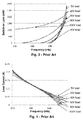
- Fig. 2 shows a characteristic curve of the load current in dependence on the switching frequency for different load voltages using a switching converter according to Fig. 1 .
- the switching frequency of the signals sig1 and sig2 varies in a range from 250 Kilohertz to 600 Kilohertz.
- Fig. 3 shows a characteristic curve of the switch-on losses in dependence on the switching frequency for different load voltages using a switching converter according to Fig. 1 .
- the switching frequency of the signals sig1 and sig2 varies in a range from 250 Kilohertz to 600 Kilohertz.
- the switch-on losses vary between nearly 0 Milliwatts for a load voltage V load of 5 volts and 1500 Milliwatts for a load voltage V load of 100 volts.
- an increase of the load voltage V load heavily increases the switching losses of the switching elements Q1, Q2 upon a certain switching frequency.
- This disadvantageous effect can be slightly reduced by using an LCC converter instead of an LLC converter according to Fig. 1 .
- the LCC converter reduces the switch-on losses and decreases the loading effects as shown in Fig. 4 and in Fig. 5 .
- a first exemplary embodiment of a switching converter according to the invention is shown.
- a rectifying section 1 according to the invention is shown.
- the switching converter according to Fig. 6 also incorporates a half bridge section H (not shown), a resonant section R (not shown) and a transformer T as shown in Fig. 1 .
- a variable resistance R Var is used in Fig. 6 .
- the variable resistance R Var allows the load to be maintained as the load voltage V load is reduced.
- the variable resistance R Var can be realized by applying a control-signal to the gate node of a FET.
- the variable resistance R Var solves the problem of the reduced load voltage V load .
- variable capacitance or a variable inductance could be used instead of the variable resistance R Var . This would additionally lead to less power losses.
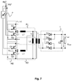
- a second exemplary embodiment of a switching converter according to the invention is shown.
- the switching converter comprises a first half-bridge section H1 connected to a first resonant section R1.
- a second half-bridge section H2 connected to a second resonant section R2 is connected.
- the shunt inductor L2 of the first resonant section R1 is also the shunt inductor L2 of the second resonant section R2.
- the first half bridge H1 comprises a series connection of two switching elements Q1 and Q2 which are applied with switching signals sig1, sig2 in an alternating manner.
- the output of the half bridge section H1 is applied to a first node of the resonant section R1 that comprises the first capacitance C1, the resonance inductance L1 and the shunt inductor L2.
- Both half-bridge sections H1, H2 are built identically.
- Both resonant sections R1, R2 are built identically.
- the output of the resonant sections R1, R2 is applied to a primary winding of the transformer T.
- the secondary coil of the transformer T comprises the rectifying section 1, which is a full-bridge rectifier using rectifying diodes D1, D2, D3 and D4.
- a charging capacitor C2 is used to smooth the output of the rectifying diodes D1 to D4.
- the output of the rectifying unit 1 is connected to the load.
- a lighting means as a load means that the load is variable.
- a zero ampere load current I load is achievable. This is obtained by varying the relative phase ⁇ of the half bridge sections H1 and H2. This is achieved by a phase shifter unit P. If the phases ⁇ of the two half-bridge sections H1 and H2 have a phase relation of 180°, the current will flow from the resonance inductor L1 of the first resonant section R1 to the resonance inductor L1 of the second resonant section R2, while absolutely no current will flow to the load connected via rectifying unit 1 to the transformer T. Thus, the current I load is zero amperes, while no switching losses occur or the switching frequency has to be increased.
- varying the phase ⁇ of the half bridge sections H1, H2 will cause an inductive reactive current to appear as inductive, resistive or capacitive.
- a third exemplary embodiment of a switching converter according to the invention is shown.
- the phase shifter P is only shown very schematically, although it is connected as shown in Fig. 7 .
- each switching element Q1, Q2 is connected in parallel to a switching capacitance C Q .
- the switching capacitance C Q is necessary to store the energy applied when the appropriate switching element Q1 or Q2 is turned-off.
- FIG. 10 an LLC converter with a passive voltage doubler rectifying unit 1 is shown.
- an active rectifier topology is used therein.
- This active rectifier topology has two parallel circuits of respectively one switching element D1, D2 across a capacitor C4.
- the diode D1 In a first phase from the current flow of a negative current to a positive current, the diode D1 will be conducting, such that the current through the shunt inductor L2 of the resonant section R will essentially flow into the capacitor C4 of the switching element D1 and then out of this capacitor C4 back to the shunt inductor L2. Such, there will be a substantial current flow through the shunt inductor L2 without a current I load at the load.
- the diode D2 In a second phase of current flow through the shunt inductor L2 from a positive current to a negative current, the diode D2 will be switched conductive.
- the load current I load is decoupled from the current I R through the shunt inductor L2 in an adjustable manner, allowing to reduce the load current I load to a zero amperes current.
- the diodes D1 and D2 are replaced by respective FETs Q3 and Q4. Those FETs are applied with respective switching signals sig1' and sig2'.
- the phase ⁇ of the switching signals sig1' and sig2' of the FETs Q3 and Q4 relative to the signals sig1 and sig2 of the FETs Q1 and Q2 in dependence on the current I R flowing through the shunt inductor L2, the decoupling/coupling between the current I R flow through the shunt inductor L2 and the current I load through the load can be adjusted essentially in a continuous manner.
- the FETs Q3 and Q4 can be controlled in a different manner (not shown).
- the switching converter becomes the ability to control the current I load .
- Fig. 10 and Fig. 11 require a control unit for the switching signals sig1, sig2, applied to the FETs Q3, Q4 on the secondary side of the transformer T which is applied with an information representing the timing of the switching of the switching elements Q1 and Q2 of the half-bridge section H.
- This control unit is part of a ballast for lighting means.
- This approach gives a synchronous type of rectification with the advantage of controlling the inductors currents I R so that current I load can be decreased to zero amperes.
- one can arrive at a dimming from 0 % to 100 % of the load current I load even when having a constant switching frequency of the switching elements Q1, Q2 of the switched converter and by keeping the current flow I R through the shunt inductor L2 of the switched converter constant.
- Fig. 12 shows a characteristic curve of the load current in dependence on the relative phase-shift for different load voltages using the inventive switching converter. As can be seen, the load current I load in relation to the relative phase ⁇ is approximately equal also when the load voltage V load decreases.
- Fig. 13 shows a characteristic curve of the switch-on losses in dependence on the relative phase-shift for different load voltages using the inventive switching converter. It can be seen that the switching-on losses are drastically reduced using the inventive switching converter.
- the inventive concept proposed herein introduces two components of current in the shunt inductor L2.
- the first component is in quadrature to the second component, so called 90° phase shifted, and contributes no current V load to the load.
- the quadrature component is still a current that is flowing in the shunt inductor L2 and produces a voltage across the shunt inductor L2. Therefore, even in the complete absence of any load current I load , the quadrature component is still present and capable of controlling the output voltage V load .
Landscapes
- Engineering & Computer Science (AREA)
- Power Engineering (AREA)
- Physics & Mathematics (AREA)
- Microelectronics & Electronic Packaging (AREA)
- Optics & Photonics (AREA)
- Dc-Dc Converters (AREA)
- Circuit Arrangements For Discharge Lamps (AREA)
Abstract
Description
- The invention relates to a switching converter, preferably a resonant converter of a ballast for driving a lighting means. The invention further refers to a ballast for a lighting means comprising the switching converter.
- Driver circuits for operating lighting means are well known in the prior art. For instance a switching converter is used as a driver circuit.
- A switching converter regulates the output voltage or the output current through a load by switching an inductance element by means of a switching element.
- Switching converters for lighting means, such as a light emitting diode, short: LED, or a discharge lamp, are used to provide a DC supply voltage or a DC supply current in order to operate the lighting means.
- A switching converter that uses a resonant circuit is hereinafter referred to as a resonant converter. Resonant converters are electrical circuits which can be supplied with an AC voltage and which are connected to the lighting means, such as one or more LEDs, in order to operate the lighting means electrically in a well defined manner.
- A typical example of a resonant converter is a switching converter that comprises an LLC resonant circuit, hereinafter referred to as LLC converter.
- A LLC converter is known per se from document
WO 2014/060899 A2 . In an LLC converter, an AC voltage is generated by a half-bridge section and provided to a resonant section. The energy, which is supplied with the AC voltage flows into the resonant section and is partially transmitted to the load of a transformer. - The resonant section is composed of a (series) resonant circuit which is powered by the AC voltage of the half-bridge section. The resonant section provides a resonant tank. The resonant section in turn supplies a primary winding of a transformer. The supply voltage for supplying the lighting means typically is a DC supply voltage, which is generally achieved by means of a rectifying section. The transformer's secondary winding supplies the rectifying section which in turn directly supplies the lighting means.
- If an LLC converter is used as a resonant converter, the resonant section of the LLC converter is composed of a resonance capacitor C1, a resonance coil L1 and preferably a shunt inductor L2. The optional shunt inductor L2 is basically used to transport the provided AC power to the load via the transformer's coils. The transformer is used as a galvanic barrier between the provided AC voltage and the required DC voltage for operating the lighting means. This galvanic isolation might be a safety requirement when operating lighting means.
- In practical realizations, components of the transformer are usually combined with components of the resonant section since the transformer does not have ideal signal transmission behaviour.
- A drawback of this known concept is the limitation of varying the voltage of the lighting means below a certain threshold value. The limiting factor in such a switching converter is the switched inductance element. The limitations are becoming apparent as requirements for dimming a lighting means to 1 percent or less over a range of a lighting means voltage are running into difficulties.
- This problem is clear when considering that a switching converter is basically limiting load current by increasing the impedance of the switched inductor. A zero ampere load current would require an infinite frequency if the load voltage is lower than a critical level, which is impossible to achieve in real switching converters.
- When the load of the switching converter comprises a low resistance value or the load voltage should be reduced to small values due to a dimming instruction, the switching frequency of the switching converter needs to be very high. Thus, the current through the switched inductor needs to be very low. This causes problems with the proper switching of the switching element of the half-bridge section of the switching converter. To obtain a proper switching, some current has to flow across these switching elements of the half-bridge section in view of capacity effects.
- Additionally, the LLC converter is designed for providing constant load voltages. In such a constant load voltage scenario, the switched inductance element loads the transformer's primary winding and enables the converter to control the load current down to zero at a nominal load voltage. This additionally requires a resonant tuning of all resonant elements which are coupled in series to the switched inductance. In such a scenario, the nominal load voltage is nearly constant. In contrast, when driving a lighting means, the expectation is to drive the lighting means of a varying load voltage. This causes the switched inductance element to produce a varying loading effect. Clearly, as the load voltage reduces, the load from the switched inductance element also reduces which causes problems when attempting to control a near zero ampere load current.
- Additionally, also the switch-on losses of the switching elements in the half-bridge section would increase.
- Thus, there is a need to provide a switching converter for driving a load with variable load voltage without the above-mentioned drawbacks. Preferably, the switching frequency of the switching elements of the half-bridge converter should not be changed.
- The above identified drawbacks are avoided using a switching converter as claimed in the
independent claim 1 and using a ballast as claimed in the independent claim 17. Advantageous embodiments can be derived from the respective dependent patent claims. - According to a first aspect of the invention, a switching converter, preferably a resonant converter of a ballast for driving a lighting means, is described. The switching converter at least comprises a half bridge section, wherein the half bridge section comprises a first switching element and a second switching element connected in series, wherein the first switching element and the second switching element are switched alternating. Furthermore the switching converter comprises a resonant section which may comprise an optional shunt inductor. Furthermore the switching converter comprises a rectifying section decoupled from the half-bridge section by means of a transformer, wherein the rectifying section provides a variable load voltage to a load and wherein the current through the resonant section is decoupled in an adjustable manner from the current through the load.
- A half-bridge section uses two switching elements, such as field effect transistors, short: FET. The first switching element is open while the second switching element is closed, thus obtaining an alternating switching. This anti-phased driving of the switching elements leads to a class AB amplifier, wherein each switching element operates the same way but also conducts a small amount of the other half. As a result, the region, where both devices simultaneously are nearly off, is reduced.
- The half-bridge section is one half-bridge section of a full-bridge section, also called H-bridge. An H-bridge is an electronic circuit that enables a voltage to be applied across a load in either direction. The term H-bridge is derived from the typical graphical representation of such a circuit. An H-bridge is built with four switches, wherein switches S1 and S2 are arranged in series and switches S3 and S4 are arranged in series. The series arranged switches are arranged in parallel. A load is arranged in-between each connection point of the series connection of the switches S1, S2 and S3, S4. When the switches S1 and S4 are closed and switches S2 and S3 are open, a positive voltage will be applied across the load.
- Using the nomenclature above, the switches S1 and S2 should never be closed at the same time, as this would cause a short circuit on the input voltage source. The same applies to the switches S3 and S4. This condition is known as shoot-through.
- The variable load voltage applied to the load leads to a varying loading effect at the resonant section. This varying load effect is dependent on the load voltage. A compensation of a decreasing load is achieved by decoupling the current in an adjustable manner. Thus, the load is maintained for the switching converter as the voltage load is reduced, preferably based on a dimming requirement or a dimming command. This leads to a switching converter which has variable load voltages but can be driven to zero ampere of load current through the load.
- In a preferred embodiment, the switching circuit is an LLC converter that comprises a series connection of a resonance capacitance, a resonance inductance and an optional shunt inductor as the resonant section. The shunt inductor is the inductance which comprises the limiting current by increasing its impedance. As lower the voltage across the inductance, as higher is the impedance of the inductance. The varying of the load voltage leads to a varying of the loading effect. Therefore, it is necessary to adjust the coupling effect of the current from the resonant section to the current through the load.
- In a preferred embodiment, the inductor value of the resonance inductor is approximately five times, preferably eight times, more preferably 10 times higher than the inductor value of the shunt inductor. This leads to a very small resonance inductor which leads to a very accurate switching converter.
- In a preferred embodiment, a variable resistance element is connected in parallel to the rectifying circuit. A resistance connected across the load reduces the range of the required control, wherein a low load voltage would reduce the loading effect. Thus, the loading is maintained as the load voltage is reduced, preferably by using a FET.
- In a preferred embodiment, a variable capacitance or inductance element is connected in parallel to the rectifying circuit. Thus, the loading is maintained as the load voltage is reduced. This avoids the power loss problem that occurs when using a variable resistance.
- In a more preferred embodiment, the half bridge section is a first half bridge section and the resonant section is a first resonant section. The switching converter further comprises a second half bridge section and a second resonant section, wherein the first half bridge section and the first resonant section are connected in parallel to the second half bridge section and the second resonant section and wherein the shunt inductor of the first resonant section is also the shunt inductor of the second resonant section. The shunt inductor is thus used in the first resonant section and the second resonant section. It should be noted, that the two parallel half-bridge sections do not lead to a full H-bridge as described above.
- The second half-bridge section leads to an inductive reactive current which appears as inductive, resistive or capacitive. Thus, the voltage across the first resonant section and the second resonant section can be generated even when the load voltage is zero volts. So, no change in the switching frequency of the switching elements in the half-bridge section is necessary.
- The currents through the first switching element and the second switching element at higher ampere levels are now possible. Using a second half-bridge section allows the use of a standardized rectifying section in the switching converter, because the control of the varying load voltage is obtained by the primary winding of the transformer of the switching converter.
- In a more preferred embodiment, the switching signals of the first switching section are phase-shifted to the switching signals of the second switching section, wherein the phase-shift is variable, preferably gradually varied from 180 degree phase-shift to zero degree phase-shift. If the phases of the two half-bridge sections have a phase relation of 180°, the current will flow from the first resonant section of the first half-bridge section to the second resonant section of the second half-bridge section, while no current will flow to the load connected to the rectifying section. The phase-shifting is obtained by using a phase shifting unit.
- By gradually changing the phase difference between the switching signals of the first half-bridge section and the second half-bridge section from 180° to 0°, the current through the load can be increased such that a phase difference of 0° causes a power delivered to the load which is twice the power delivered by the individual half-bridge section.
- It should be noted that each half bridge section is driven by the anti-phased switching signals. The 180° phase difference between those two switching signals stays constant when changing the relative phase between the switching signals for the half bridge sections.
- In a preferred embodiment the current of the first half-bridge section is 90° phase-shifted to the current of the second half-bridge section. Thus, one half-bridge section applies current, wherein the other half-bridge section does not apply current. Thus, only one of the half-bridge sections produces voltage across the shunt inductor of the resonant section. However, the 90° phase shift current is still a current that is flowing in the shunt inductor of the resonant section and produces a voltage across this inductor. Therefore, even in the complete absence of any load current, the appropriate half-bridge section is still present and capable of controlling the output voltage of the switching converter. Thus, the load current can be set to zero amperes although the load voltage is decreased.
- In a more preferred embodiment the rectifying section is an active rectifying section. Active in the sense of the invention is referred to a rectifying section on which energy is supplied to control the rectifying section and its rectification.
- In a preferred embodiment the rectifying section comprises a first switching element and a second switching element connected in series, wherein the first switching element and the second switching element are switched alternating. Thus, a half-wave rectifier is achieved that is controllable via switching signals.
- For a current from the secondary winding of the transformer, which flows from a negative current value to a positive current value, the first switching element of the rectifying section is conducting such that the resonant sections current will essentially flow into the switching element and then out of this switching element back to the resonant section. Such, there will be a substantial current flow through the switching inductance without any current arriving at the load connected at the output side.
- In a preferred embodiment, the switching elements are FETs. Applying a control signal to the FET, which is independent from the switching signal of the switching elements of the switching section, leads to a switching converter with the ability to control the load currents as describes above.
- Alternatively, the switching signal of the first switching element of the rectifying section is the switching signal of the first switching element of the half bridge section. The switching signal of the second switching element of the rectifying section is the switching signal of the second switching element of the half bridge section. Thus, an active synchronous rectifier is obtained. A current, which flows through the resonant section, will flow in to the switching elements in dependence on a switching phase, wherein substantially the current flows through the resonant section without current applied to the load. The switching signal is preferably applied to a control input of the FET.
- In a preferred embodiment the switching signal of the rectifying section is phase-shifted to the switching signal of the rectifying section, wherein the phase shift is variable, preferably gradually varied from 180° phase shift to 0° phase shift. Thus, a current through the load can be increased, wherein a phase shift of 0° leads to a power which is twice the power of the half-bridge section. Thus, the current from the resonant section is decoupled in an adjustable manner from the current through the load.
- In a preferred embodiment, a capacitance is arranged in parallel to each switching element of the half bridge section and/or the rectifying section, wherein the capacitance preferably comprises a capacitance value of a few Nano-Farads. Thus, the capacitance stores the charge obtained from the current and does not provide the current to the load.
- In a preferred embodiment, the load is a lighting means, wherein the current through the lighting means is variable for dimming the lighting means.
- In a preferred embodiment, the dimming range is from 0 Percent to 100 Percent of the load current, while the switching frequency of the switching converter stays constant.
- In a second aspect of the invention, a ballast for a lighting means, especially an LED is provided. The ballast comprises a switching converter as described above, wherein a switching signal is generated by a control unit of the ballast and wherein the switching signal is applied to the switching converter.
- In a preferred embodiment the switching frequency of the switching signal is constant over a dimming range of the lighting means, preferably wherein the switching frequency is in the frequency range between 200 Kilohertz and 600 Kilohertz.
- The control unit is configured to control a phase shifting unit in that a load current through the shunt inductor is decoupled from the load current in a variable manner. Thus, a variable phase-shifting is achieved by the phase shifting unit.
- In the following, exemplary embodiments of the invention are described with reference to drawings. Those exemplary embodiments do not limit the scope of the invention. The same reference signs in different drawings indicate the same elements or at least the same functions unless otherwise stated. In the drawings:
- Fig. 1
- shows a switching converter according to the prior art;
- Fig. 2
- shows a characteristic curve of the load current in dependence on the switching frequency for different load voltages using a switching converter according to
Fig. 1 ; - Fig. 3
- shows a characteristic curve of the switch-on losses in dependence on the switching frequency for different load voltages using a switching converter according to
Fig. 1 ; - Fig. 4
- shows a characteristic curve of the load current in dependence on the switching frequency for different load voltages using another switching converter according to prior art;
- Fig. 5
- shows a characteristic curve of the switch-on losses in dependence on the switching frequency for different load voltages using another switching converter according to prior art;
- Fig. 6
- shows a first exemplary embodiment of a switching converter according to the invention;
- Fig. 7
- shows a second exemplary embodiment of a switching converter according to the invention;
- Fig. 8
- shows a third exemplary embodiment of a switching converter according to the invention;
- Fig. 9
- shows a characteristic curve of the load current in dependence on the phase-shift for different load voltages using the inventive switching converter;
- Fig. 10
- shows a fourth exemplary embodiment of a switching converter according to the invention;
- Fig. 11
- shows a fifth exemplary embodiment of a switching converter according to the invention;
- Fig. 12
- shows a characteristic curve of the load current in dependence on the relative phase-shift for different load voltages using the inventive switching converter;
- Fig. 13
- shows a characteristic curve of the switch-on losses in dependence on the relative phase-shift for different load voltages using the inventive switching converter.
- In
Fig. 1 an LLC converter according to the prior art is shown. The LLC converter comprises a half-bridge section H, a resonant section R, a transformer T and arectifying section 1. The rectifyingsection 1 supplies a load with a constant voltage Vload and a current ILoad. The half-bridge section H comprises a first switching element Q1 and a second switching element Q2. The switching elements Q1, Q2 are FETs. The first switching element Q1 is switched by a first switching signal sig1. The second switching element Q2 is switched by a second switching signal sig2. The first switching signal sig1 is 180° phase shifted to the second switching signal sig2. This phase-shift stays constant. - The LLC converter according to
Fig. 1 can be operated at two resonant frequencies fr1 fr2. The first resonance frequency fr1 is determined by the resonance capacitance C1 and the resonance inductor L1. The second resonance frequency fr2 is determined by the resonance capacitance C1, the resonance inductor L1, the optional shunt inductor L2 and the specific load condition. As load becomes more resistive, the resonance frequency fr2 will shift to higher frequencies. - Note that the shunt inductor L2 is preferably not present when using a LLC converter without following isolation stage (transformer). The invention also relates to such LLC converters with following isolation stage, e.g. implemented as a transformer.
- In a first switching interval, the resonance inductor L1 is resonant with resonance capacitance C1. Thus, the shunt inductor L2 is clamped by the load voltage Vload. When the current through the resonance inductor L1 is the same level as the current through the shunt inductor L2, the resonance of the resonance inductor L1 and the resonance capacitance C1 is stopped. Instead, now the shunt inductor L2 will participate into the resonant and the second switching interval begins.
- During the second switching interval the resonant components will change to resonance capacitance C1 and shunt inductor L2 in series with resonance inductor L1. Thus, the resonance frequencies fr1, fr2 at different switching intervals is different. Because of the resonant between resonance capacitance C1 and shunt inductor L2, a peak on the gain appears at the second resonance frequency fr2.
- In case the second switching element Q2 is turned off, the current through resonance inductor L1 is negative and will flow through the body diode of the first switching element Q1, which creates a zero voltage.
- The limitation of such an LLC converter are becoming apparent as requirements for dimming LEDs to 1 % or less over a range of a load voltage Vload are running into difficulties. This problem is clear when considering that the LLC converter according to
Fig. 1 is basically limiting load current Iload by increasing the impedance ZL2 of the shunt inductor L2. A load current Iload of zero amperes requires an infinite switching frequency of the signals sig1 and sig2 if the load voltage Vload is lower than a critical voltage level. - The LLC converter according to
Fig. 1 is well suited for providing constant load voltages Vload. In case a lighting means should be driven with a dimming range from 0 % to 100 %, the expectation is to drive lighting means of varying the voltage and this causes the shunt inductor L2 to produce a varying load effect. Clearly, as the load voltage Vload reduces, the load from shunt inductor L2 also reduces, which causes problems when attempting to control a zero amperes load current Iload. - The arrangement according to
Fig. 1 comprises a dead time between the first switching element Q1 and the second switching element Q2 of approximately 400 ns. The resonant section R comprises a resonance capacitance C1 of 10 Nano-Farads, a resonance inductor L1 of 100 Microhenry and a shunt inductor L2 of 1 Millihenry. The supply voltage Vsupply is 100 volts. - In the conventional LLC converter, the voltage across the shunt inductor L2 is determined by the load current Iload. The load current Iload implies no voltage drop across the shunt inductor L2. There is no capability to control the output voltage Vload. Additionally, low currents make commutations of the switching elements Q1, Q2 impossible to achieve.
-
Fig. 2 shows a characteristic curve of the load current in dependence on the switching frequency for different load voltages using a switching converter according toFig. 1 . The switching frequency of the signals sig1 and sig2 varies in a range from 250 Kilohertz to 600 Kilohertz. - Even with this 3:1 frequency range, the load current Iload is only reduced to roughly 20 Percent of the full load current Iload at a low load voltage Vload. Thus, no sufficient regulation can be obtained when changing the frequency of the switching signals sig1 and sig2.
-
Fig. 3 shows a characteristic curve of the switch-on losses in dependence on the switching frequency for different load voltages using a switching converter according toFig. 1 . Again, the switching frequency of the signals sig1 and sig2 varies in a range from 250 Kilohertz to 600 Kilohertz. At frequencies above 440 Kilohertz, the switch-on losses vary between nearly 0 Milliwatts for a load voltage Vload of 5 volts and 1500 Milliwatts for a load voltage Vload of 100 volts. Thus, an increase of the load voltage Vload heavily increases the switching losses of the switching elements Q1, Q2 upon a certain switching frequency. - This disadvantageous effect can be slightly reduced by using an LCC converter instead of an LLC converter according to
Fig. 1 . The LCC converter reduces the switch-on losses and decreases the loading effects as shown inFig. 4 and inFig. 5 . - As can be derived from
Fig. 4 andFig. 5 , such an LCC converter gives control down to a zero amperes load current Iload only for a load voltage Vload down to 40 volts. At lower load voltages Vload the load current Iload cannot be reduced to zero amperes. Thus, using an LCC converter will not lead to a sufficient improvement over the known LLC converter according toFig. 1 . - In
Fig. 6 a first exemplary embodiment of a switching converter according to the invention is shown. Precisely, arectifying section 1 according to the invention is shown. The switching converter according toFig. 6 also incorporates a half bridge section H (not shown), a resonant section R (not shown) and a transformer T as shown inFig. 1 . To avoid unnecessary repetitions, only the differences toFig. 1 are illustrated hereinafter. To obtain the inventive concept of an adjustable decoupling of the current IR through the shunt inductor L2 from the load current Iload a variable resistance RVar is used inFig. 6 . The variable resistance RVar allows the load to be maintained as the load voltage Vload is reduced. The variable resistance RVar can be realized by applying a control-signal to the gate node of a FET. The variable resistance RVar solves the problem of the reduced load voltage Vload. - Alternatively, and not shown in
Fig. 6 , a variable capacitance or a variable inductance could be used instead of the variable resistance RVar. This would additionally lead to less power losses. - In
Fig. 7 , a second exemplary embodiment of a switching converter according to the invention is shown. The switching converter comprises a first half-bridge section H1 connected to a first resonant section R1. In parallel to this series connection, a second half-bridge section H2 connected to a second resonant section R2 is connected. The shunt inductor L2 of the first resonant section R1 is also the shunt inductor L2 of the second resonant section R2. - The first half bridge H1 comprises a series connection of two switching elements Q1 and Q2 which are applied with switching signals sig1, sig2 in an alternating manner. The output of the half bridge section H1 is applied to a first node of the resonant section R1 that comprises the first capacitance C1, the resonance inductance L1 and the shunt inductor L2.
- Both half-bridge sections H1, H2 are built identically. Both resonant sections R1, R2 are built identically.
- The output of the resonant sections R1, R2 is applied to a primary winding of the transformer T. The secondary coil of the transformer T comprises the rectifying
section 1, which is a full-bridge rectifier using rectifying diodes D1, D2, D3 and D4. A charging capacitor C2 is used to smooth the output of the rectifying diodes D1 to D4. The output of the rectifyingunit 1 is connected to the load. - Using a lighting means as a load means that the load is variable. Thus, it needs to be assured that a zero ampere load current Iload is achievable. This is obtained by varying the relative phase ϕ of the half bridge sections H1 and H2. This is achieved by a phase shifter unit P. If the phases ϕ of the two half-bridge sections H1 and H2 have a phase relation of 180°, the current will flow from the resonance inductor L1 of the first resonant section R1 to the resonance inductor L1 of the second resonant section R2, while absolutely no current will flow to the load connected via rectifying
unit 1 to the transformer T. Thus, the current Iload is zero amperes, while no switching losses occur or the switching frequency has to be increased. - By gradually changing the relative phase difference Δϕ between the switching signals sig1, sig2 of the first half bridge H1 and the switching signals sig1, sig2 of the half bridge H2 from 180° to 0°, the current Iload through the load can be increased, such that for example having a phase difference of ϕ = 0°, the power delivered to the load will be twice the power delivered by the individual half-bridge sections H1 and H2. Clearly, varying the phase ϕ of the half bridge sections H1, H2 will cause an inductive reactive current to appear as inductive, resistive or capacitive. In this way it becomes possible to generate a voltage across resonance inductor L1 of the first half-bridge section H1 and the resonance inductor L1 of the second half-bridge section H2, even when the load current Iload is zero amperes. No variation of the frequency of the alternating switching signals sig1 and sig2 is needed. This approach also enables switching currents to be maintained at sufficiently high levels that commutation can still occur, which is a problem when frequencies increase drastically and currents are reduced.
- In
Fig. 8 a third exemplary embodiment of a switching converter according to the invention is shown. In the following only the differences between the second exemplary embodiment and the third exemplary embodiment are described to avoid repetitions. The phase shifter P is only shown very schematically, although it is connected as shown inFig. 7 . According toFig. 8 , each switching element Q1, Q2 is connected in parallel to a switching capacitance CQ. The switching capacitance CQ is necessary to store the energy applied when the appropriate switching element Q1 or Q2 is turned-off. - Simulations according to
Fig. 9 show that this switching converter according to the invention can swing the phase ϕ to create the transfer characteristic. When the phase swings to in-phase, the converter looks like a standard LLC-converter where the two parallel FETs Q1, Q2 are switching the two parallel resistance inductors L1 of the respective resonant sections R1, R2. This situation yields to a full load current Iload. No differences in the load current Iload is obtained by changing the relative phase ϕ of the first switching signal sig1 and the second switching signal sig2 for the specific half bridge section H1, H2 at different load voltages Vload. Potential advantages of this approach are that all control is on the primary side and a straight forwardpassive rectifying unit 1 can be used according to these exemplary embodiments. - If the problem of controlling switching at the secondary side of the transformer T can be overcome at some stage, another possibility becomes apparent, which is shown in the fourth exemplary embodiment according to
Fig. 10 . - According to
Fig. 10 an LLC converter with a passive voltagedoubler rectifying unit 1 is shown. On the secondary side of the transformer T an active rectifier topology is used therein. This active rectifier topology has two parallel circuits of respectively one switching element D1, D2 across a capacitor C4. - In a first phase from the current flow of a negative current to a positive current, the diode D1 will be conducting, such that the current through the shunt inductor L2 of the resonant section R will essentially flow into the capacitor C4 of the switching element D1 and then out of this capacitor C4 back to the shunt inductor L2. Such, there will be a substantial current flow through the shunt inductor L2 without a current Iload at the load. In a second phase of current flow through the shunt inductor L2 from a positive current to a negative current, the diode D2 will be switched conductive. Thus, the load current Iload is decoupled from the current IR through the shunt inductor L2 in an adjustable manner, allowing to reduce the load current Iload to a zero amperes current.
- Now referring to
Fig. 11 , the diodes D1 and D2 are replaced by respective FETs Q3 and Q4. Those FETs are applied with respective switching signals sig1' and sig2'. By changing the phase ϕ of the switching signals sig1' and sig2' of the FETs Q3 and Q4, relative to the signals sig1 and sig2 of the FETs Q1 and Q2 in dependence on the current IR flowing through the shunt inductor L2, the decoupling/coupling between the current IR flow through the shunt inductor L2 and the current Iload through the load can be adjusted essentially in a continuous manner. - Alternatively, the FETs Q3 and Q4 can be controlled in a different manner (not shown). Thus, the switching converter becomes the ability to control the current Iload.
- The embodiments according to
Fig. 10 and Fig. 11 require a control unit for the switching signals sig1, sig2, applied to the FETs Q3, Q4 on the secondary side of the transformer T which is applied with an information representing the timing of the switching of the switching elements Q1 and Q2 of the half-bridge section H. This control unit is part of a ballast for lighting means. - This approach gives a synchronous type of rectification with the advantage of controlling the inductors currents IR so that current Iload can be decreased to zero amperes. Thus, by adjusting the phase continuously, one can arrive at a dimming from 0 % to 100 % of the load current Iload even when having a constant switching frequency of the switching elements Q1, Q2 of the switched converter and by keeping the current flow IR through the shunt inductor L2 of the switched converter constant.
-
Fig. 12 shows a characteristic curve of the load current in dependence on the relative phase-shift for different load voltages using the inventive switching converter. As can be seen, the load current Iload in relation to the relative phase ϕ is approximately equal also when the load voltage Vload decreases. -
Fig. 13 shows a characteristic curve of the switch-on losses in dependence on the relative phase-shift for different load voltages using the inventive switching converter. It can be seen that the switching-on losses are drastically reduced using the inventive switching converter. - The inventive concept proposed herein introduces two components of current in the shunt inductor L2. The first component is in quadrature to the second component, so called 90° phase shifted, and contributes no current Vload to the load. However, the quadrature component is still a current that is flowing in the shunt inductor L2 and produces a voltage across the shunt inductor L2. Therefore, even in the complete absence of any load current Iload, the quadrature component is still present and capable of controlling the output voltage Vload.
- Further to this, the fact that a current still flows in the shunt inductor L2 even when the load current Iload is zero allows commutation of the FETs Q1, Q2 to be possible.
- All features of all embodiments described, shown and/or claimed herein can be combined with each.
- While various embodiments of the present invention have been described above, it should be understood that they have been presented by way of example only, and not limitation. Numerous changes to the disclosed embodiments can be made in accordance with the disclosure herein without departing from the spirit or scope of the invention. Thus, the breadth and scope of the present invention should not be limited by any of the above described embodiments. Rather, the scope of the invention should be defined in accordance with the following claims and their equivalents.
- Although the invention has been illustrated and described with respect to one or more implementations, equivalent alterations and modifications will occur to others skilled in the art upon the reading and understanding of this specification and the annexed drawings. In addition, while a particular feature of the invention may have been disclosed with respect to only one of several implementations, such feature may be combined with one or more other features of the other implementations as may be desired and advantageous for any given or particular application.
-
- 1
- Rectifying section
- C1
- Resonance capacitance
- C2
- Charging capacitance
- CQ
- Switching capacitance
- D1-D4
- Rectifying diode
- fr1
- First resonance frequency
- fr2
- Second resonance frequency
- H
- Half bridge section
- H1
- First half bridge section
- H2
- Second half bridge section
- Vload
- Load current
- IR
- current through shunt inductor
- L1
- Resonance inductance
- L2
- Shunt inductance
- P
- Phase Shifter
- Q1
- First switching element
- Q2
- Second switching element
- Q3
- First rectifying transistor
- Q4
- Second rectifying transistor
- R
- Resonant section
- R1
- First resonant section
- R2
- Second resonant section
- sig1
- First switching signal
- sig2
- Second switching signal
- T
- Transformer
- Vload
- Load voltage
- Vsupply
- Supply voltage
Claims (19)
- A switching converter, preferably a resonant converter of a ballast for driving a lighting means, the switching converter at least comprises:- a half bridge section, wherein the half bridge section comprises a first switching element and a second switching element connected in series, wherein the first switching element and the second switching element are switched alternating;- a resonant section preferably comprising a shunt inductor;- a rectifying section decoupled from the half-bridge section by means of a transformer, wherein the rectifying section provides a variable load voltage to a load; and wherein the current through the resonant section is decoupled in an adjustable manner from the current through the load.
- The switching converter according to claim 1, wherein the switching circuit is an LLC converter that comprises a series connection of a resonance capacitance, a resonance inductance and the shunt inductor.
- The switching converter according to claim 2, wherein the inductor value of the resonance inductance is approximately 5 times, preferably 8 times, more preferably 10 times smaller than the inductor value of the shunt inductor.
- The switching converter according to one of the preceding claims,
wherein a variable resistance element is connected in parallel to the rectifying circuit. - The switching converter according to one of the preceding claims,
wherein a variable capacitance element or variable inductance element is connected in parallel to the rectifying circuit. - The switching converter according to one of the preceding claims,- wherein the half bridge section is a first half bridge section and the resonant section is a first resonant section;- wherein the switching converter further comprises a second half bridge section and a second resonant section;- wherein the first half bridge section and the first resonant section are connected in parallel to the second half bridge section and the second resonant section; and- wherein the shunt inductor of the first resonant section is also the shunt inductor of the second resonant section.
- The switching converter according to claim 6, wherein the switching signals of the first half bridge section are phase-shifted to the switching signals of the second half bridge section, wherein the phase-shift is variable, preferably gradually varied from 180 degree phase-shift to zero degree phase-shift.
- The switching converter according to claim 6 or 7, wherein the current of the first half bridge section is 90 degree phase-shifted to the current of the second half bridge section.
- The switching converter according to one of the preceding claims,
wherein the rectifying section is an active rectifying section. - The switching converter according to one of the preceding claims,
wherein the rectifying section comprises a first switching element and a second switching element connected in series, wherein the first switching element and the second switching element are switched alternating. - The switching converter according to claim 10, wherein each switching element is a FET transistor.
- The switching converter according to claims 10 or 11,- wherein the switching signal of the first switching element of the rectifying section is also the switching signal of the first switching element of the half bridge section; and- wherein the switching signal of the second switching element of the rectifying section is also the switching signal of the second switching element of the half bridge section.
- The switching converter according to one of the claims 10 to 12,
wherein the switching signal of the first switching element of the rectifying section is phase-shifted to the switching signal of the second switching element of the rectifying section; and
wherein the phase-shift is variable, preferably gradually varied from 180 degree phase-shift to zero degree phase-shift. - The switching converter according to one of the preceding claims,
wherein a capacitance is arranged in parallel to each switching element of the half-bridge section, wherein the capacitance preferably comprises a capacitance value of few Nano-farads. - The switching converter according to one of the preceding claims,
wherein the load is a lighting means; and wherein the current through the lighting means is variable for dimming the lighting means. - The switching converter according to claim 15, wherein the dimming range is from 0 % to 100 % of the load current, while the switching frequency of the switching converter stays constant.
- A ballast for a lighting means, especially an LED, comprising a switching converter according one of the preceding claims, wherein a switching signal is generated by a control unit of the ballast and wherein the switching signal is applied to the switching converter.
- The ballast for a lighting means according to claim 17,
wherein the switching frequency of the switching signal is constant over a dimming range of the lighting means, preferably wherein the switching frequency is in the frequency range between 200 Kilohertz and 600 Kilohertz. - The ballast for a lighting means according to claim 17 or 18,
wherein the control unit is configured to control a phase shifting unit in that a load current through the shunt inductor is decoupled from the load current in a variable manner.
Applications Claiming Priority (1)
| Application Number | Priority Date | Filing Date | Title |
|---|---|---|---|
| GB1507162.4A GB2537691B8 (en) | 2015-04-22 | 2015-04-22 | A switching converter for driving variable load voltages |
Publications (3)
| Publication Number | Publication Date |
|---|---|
| EP3086625A2 true EP3086625A2 (en) | 2016-10-26 |
| EP3086625A3 EP3086625A3 (en) | 2016-11-02 |
| EP3086625B1 EP3086625B1 (en) | 2018-09-05 |
Family
ID=53488736
Family Applications (1)
| Application Number | Title | Priority Date | Filing Date |
|---|---|---|---|
| EP16166324.0A Not-in-force EP3086625B1 (en) | 2015-04-22 | 2016-04-21 | A switching converter for driving variable load voltages |
Country Status (2)
| Country | Link |
|---|---|
| EP (1) | EP3086625B1 (en) |
| GB (1) | GB2537691B8 (en) |
Cited By (2)
| Publication number | Priority date | Publication date | Assignee | Title |
|---|---|---|---|---|
| CN111446860A (en) * | 2019-01-16 | 2020-07-24 | 台达电子企业管理(上海)有限公司 | DC/DC converter and control method thereof |
| US11063523B2 (en) | 2019-01-16 | 2021-07-13 | Delta Electronics (Shanghai) Co., Ltd | DC/DC converter and control method thereof |
Families Citing this family (1)
| Publication number | Priority date | Publication date | Assignee | Title |
|---|---|---|---|---|
| WO2020257962A1 (en) * | 2019-06-24 | 2020-12-30 | Texas Instruments Incorporated | Switching converter with multiple drive stages and related modes |
Citations (1)
| Publication number | Priority date | Publication date | Assignee | Title |
|---|---|---|---|---|
| WO2014060899A2 (en) | 2012-10-18 | 2014-04-24 | Koninklijke Philips N.V. | Driver device and driving method for driving a load |
Family Cites Families (2)
| Publication number | Priority date | Publication date | Assignee | Title |
|---|---|---|---|---|
| JP5636057B2 (en) * | 2009-09-30 | 2014-12-03 | コーニンクレッカ フィリップス エヌ ヴェ | LED driver dimming |
| KR20130073611A (en) * | 2011-12-23 | 2013-07-03 | 삼성전기주식회사 | Power supplying apparatus |
-
2015
- 2015-04-22 GB GB1507162.4A patent/GB2537691B8/en not_active Expired - Fee Related
-
2016
- 2016-04-21 EP EP16166324.0A patent/EP3086625B1/en not_active Not-in-force
Patent Citations (1)
| Publication number | Priority date | Publication date | Assignee | Title |
|---|---|---|---|---|
| WO2014060899A2 (en) | 2012-10-18 | 2014-04-24 | Koninklijke Philips N.V. | Driver device and driving method for driving a load |
Cited By (4)
| Publication number | Priority date | Publication date | Assignee | Title |
|---|---|---|---|---|
| CN111446860A (en) * | 2019-01-16 | 2020-07-24 | 台达电子企业管理(上海)有限公司 | DC/DC converter and control method thereof |
| US11063523B2 (en) | 2019-01-16 | 2021-07-13 | Delta Electronics (Shanghai) Co., Ltd | DC/DC converter and control method thereof |
| CN111446860B (en) * | 2019-01-16 | 2021-09-21 | 台达电子企业管理(上海)有限公司 | DC/DC converter and control method thereof |
| US11190104B2 (en) | 2019-01-16 | 2021-11-30 | Delta Electronics (Shanghai) Co., Ltd | DC/DC converter and method for controlling phase shift angle thereof |
Also Published As
| Publication number | Publication date |
|---|---|
| GB2537691B8 (en) | 2021-10-20 |
| EP3086625B1 (en) | 2018-09-05 |
| GB2537691A (en) | 2016-10-26 |
| GB2537691A8 (en) | 2021-10-20 |
| GB201507162D0 (en) | 2015-06-10 |
| EP3086625A3 (en) | 2016-11-02 |
| GB2537691B (en) | 2021-08-04 |
Similar Documents
| Publication | Publication Date | Title |
|---|---|---|
| JP6942852B2 (en) | Insulated DC / DC converter for wide output voltage range and its control method | |
| EP2770623B1 (en) | Resonant converter | |
| JP4987389B2 (en) | Power supply topology for inverter operation and power factor correction operation | |
| US5155670A (en) | Bootstrap modified topologies for wide-input range switchmode DC to DC converters | |
| US20130021827A1 (en) | System and method for envelope tracking power supply | |
| JP2005503099A (en) | Power converter with two regulated outputs | |
| US9241380B2 (en) | Hybrid dimming control techniques for lighting drivers | |
| US20150229225A1 (en) | Resonant converters and control methods thereof | |
| US20120026754A1 (en) | Double phase-shifting full-bridge dc-to-dc converter | |
| US20120062147A1 (en) | High efficiency drive method for driving LED devices | |
| US20110194317A1 (en) | Stacked flyback converter with independent current loop control | |
| US5977753A (en) | Buck regulator with plural outputs | |
| KR20030076565A (en) | Single-stage pfc + ballast control circuit/general purpose power converter | |
| CN111224551B (en) | Power Converters | |
| EP3086625B1 (en) | A switching converter for driving variable load voltages | |
| JP2010506559A (en) | Primary resonant inverter circuit that feeds the secondary circuit | |
| EP4275271A1 (en) | An isolated bidirectional active-half-bridge resonant dc-dc power converter | |
| EP2638628B1 (en) | Voltage converter comprising a storage inductor with one winding and a storage inductor with two windings | |
| US20230188047A1 (en) | Power converter circuit | |
| JP2023502975A (en) | direct power converter | |
| US12068682B2 (en) | Control method and circuit for phase shift regulation of interleaved converters at variable switching frequency | |
| WO2019170781A1 (en) | A resonant power converter | |
| US7663324B2 (en) | Control circuit and method for driving a gas discharge lamp | |
| CN112715000A (en) | Power supply unit and power supply system using the same | |
| TWI767271B (en) | One-sided parallel llc power converter and method of converting power |
Legal Events
| Date | Code | Title | Description |
|---|---|---|---|
| PUAI | Public reference made under article 153(3) epc to a published international application that has entered the european phase |
Free format text: ORIGINAL CODE: 0009012 |
|
| PUAL | Search report despatched |
Free format text: ORIGINAL CODE: 0009013 |
|
| AK | Designated contracting states |
Kind code of ref document: A2 Designated state(s): AL AT BE BG CH CY CZ DE DK EE ES FI FR GB GR HR HU IE IS IT LI LT LU LV MC MK MT NL NO PL PT RO RS SE SI SK SM TR |
|
| AX | Request for extension of the european patent |
Extension state: BA ME |
|
| AK | Designated contracting states |
Kind code of ref document: A3 Designated state(s): AL AT BE BG CH CY CZ DE DK EE ES FI FR GB GR HR HU IE IS IT LI LT LU LV MC MK MT NL NO PL PT RO RS SE SI SK SM TR |
|
| AX | Request for extension of the european patent |
Extension state: BA ME |
|
| RIC1 | Information provided on ipc code assigned before grant |
Ipc: H05B 41/282 20060101ALI20160929BHEP Ipc: H05B 41/392 20060101ALI20160929BHEP Ipc: H05B 33/08 20060101AFI20160929BHEP Ipc: H02M 7/48 20070101ALN20160929BHEP Ipc: H02M 3/335 20060101ALI20160929BHEP |
|
| STAA | Information on the status of an ep patent application or granted ep patent |
Free format text: STATUS: REQUEST FOR EXAMINATION WAS MADE |
|
| 17P | Request for examination filed |
Effective date: 20170227 |
|
| RBV | Designated contracting states (corrected) |
Designated state(s): AL AT BE BG CH CY CZ DE DK EE ES FI FR GB GR HR HU IE IS IT LI LT LU LV MC MK MT NL NO PL PT RO RS SE SI SK SM TR |
|
| GRAP | Despatch of communication of intention to grant a patent |
Free format text: ORIGINAL CODE: EPIDOSNIGR1 |
|
| STAA | Information on the status of an ep patent application or granted ep patent |
Free format text: STATUS: GRANT OF PATENT IS INTENDED |
|
| RIC1 | Information provided on ipc code assigned before grant |
Ipc: H05B 41/282 20060101ALI20180516BHEP Ipc: H05B 33/08 20060101AFI20180516BHEP Ipc: H02M 1/00 20060101ALN20180516BHEP Ipc: H02M 7/48 20070101ALN20180516BHEP Ipc: H05B 41/392 20060101ALI20180516BHEP Ipc: H02M 3/335 20060101ALI20180516BHEP |
|
| INTG | Intention to grant announced |
Effective date: 20180612 |
|
| GRAS | Grant fee paid |
Free format text: ORIGINAL CODE: EPIDOSNIGR3 |
|
| GRAA | (expected) grant |
Free format text: ORIGINAL CODE: 0009210 |
|
| STAA | Information on the status of an ep patent application or granted ep patent |
Free format text: STATUS: THE PATENT HAS BEEN GRANTED |
|
| AK | Designated contracting states |
Kind code of ref document: B1 Designated state(s): AL AT BE BG CH CY CZ DE DK EE ES FI FR GB GR HR HU IE IS IT LI LT LU LV MC MK MT NL NO PL PT RO RS SE SI SK SM TR |
|
| REG | Reference to a national code |
Ref country code: GB Ref legal event code: FG4D |
|
| REG | Reference to a national code |
Ref country code: CH Ref legal event code: EP |
|
| REG | Reference to a national code |
Ref country code: AT Ref legal event code: REF Ref document number: 1039453 Country of ref document: AT Kind code of ref document: T Effective date: 20180915 |
|
| REG | Reference to a national code |
Ref country code: IE Ref legal event code: FG4D |
|
| REG | Reference to a national code |
Ref country code: DE Ref legal event code: R096 Ref document number: 602016005270 Country of ref document: DE |
|
| REG | Reference to a national code |
Ref country code: NL Ref legal event code: MP Effective date: 20180905 |
|
| REG | Reference to a national code |
Ref country code: LT Ref legal event code: MG4D |
|
| PG25 | Lapsed in a contracting state [announced via postgrant information from national office to epo] |
Ref country code: GR Free format text: LAPSE BECAUSE OF FAILURE TO SUBMIT A TRANSLATION OF THE DESCRIPTION OR TO PAY THE FEE WITHIN THE PRESCRIBED TIME-LIMIT Effective date: 20181206 Ref country code: NO Free format text: LAPSE BECAUSE OF FAILURE TO SUBMIT A TRANSLATION OF THE DESCRIPTION OR TO PAY THE FEE WITHIN THE PRESCRIBED TIME-LIMIT Effective date: 20181205 Ref country code: BG Free format text: LAPSE BECAUSE OF FAILURE TO SUBMIT A TRANSLATION OF THE DESCRIPTION OR TO PAY THE FEE WITHIN THE PRESCRIBED TIME-LIMIT Effective date: 20181205 Ref country code: LT Free format text: LAPSE BECAUSE OF FAILURE TO SUBMIT A TRANSLATION OF THE DESCRIPTION OR TO PAY THE FEE WITHIN THE PRESCRIBED TIME-LIMIT Effective date: 20180905 Ref country code: RS Free format text: LAPSE BECAUSE OF FAILURE TO SUBMIT A TRANSLATION OF THE DESCRIPTION OR TO PAY THE FEE WITHIN THE PRESCRIBED TIME-LIMIT Effective date: 20180905 Ref country code: SE Free format text: LAPSE BECAUSE OF FAILURE TO SUBMIT A TRANSLATION OF THE DESCRIPTION OR TO PAY THE FEE WITHIN THE PRESCRIBED TIME-LIMIT Effective date: 20180905 Ref country code: FI Free format text: LAPSE BECAUSE OF FAILURE TO SUBMIT A TRANSLATION OF THE DESCRIPTION OR TO PAY THE FEE WITHIN THE PRESCRIBED TIME-LIMIT Effective date: 20180905 |
|
| PG25 | Lapsed in a contracting state [announced via postgrant information from national office to epo] |
Ref country code: AL Free format text: LAPSE BECAUSE OF FAILURE TO SUBMIT A TRANSLATION OF THE DESCRIPTION OR TO PAY THE FEE WITHIN THE PRESCRIBED TIME-LIMIT Effective date: 20180905 Ref country code: LV Free format text: LAPSE BECAUSE OF FAILURE TO SUBMIT A TRANSLATION OF THE DESCRIPTION OR TO PAY THE FEE WITHIN THE PRESCRIBED TIME-LIMIT Effective date: 20180905 Ref country code: HR Free format text: LAPSE BECAUSE OF FAILURE TO SUBMIT A TRANSLATION OF THE DESCRIPTION OR TO PAY THE FEE WITHIN THE PRESCRIBED TIME-LIMIT Effective date: 20180905 |
|
| PG25 | Lapsed in a contracting state [announced via postgrant information from national office to epo] |
Ref country code: EE Free format text: LAPSE BECAUSE OF FAILURE TO SUBMIT A TRANSLATION OF THE DESCRIPTION OR TO PAY THE FEE WITHIN THE PRESCRIBED TIME-LIMIT Effective date: 20180905 Ref country code: PL Free format text: LAPSE BECAUSE OF FAILURE TO SUBMIT A TRANSLATION OF THE DESCRIPTION OR TO PAY THE FEE WITHIN THE PRESCRIBED TIME-LIMIT Effective date: 20180905 Ref country code: IT Free format text: LAPSE BECAUSE OF FAILURE TO SUBMIT A TRANSLATION OF THE DESCRIPTION OR TO PAY THE FEE WITHIN THE PRESCRIBED TIME-LIMIT Effective date: 20180905 Ref country code: IS Free format text: LAPSE BECAUSE OF FAILURE TO SUBMIT A TRANSLATION OF THE DESCRIPTION OR TO PAY THE FEE WITHIN THE PRESCRIBED TIME-LIMIT Effective date: 20190105 Ref country code: RO Free format text: LAPSE BECAUSE OF FAILURE TO SUBMIT A TRANSLATION OF THE DESCRIPTION OR TO PAY THE FEE WITHIN THE PRESCRIBED TIME-LIMIT Effective date: 20180905 Ref country code: CZ Free format text: LAPSE BECAUSE OF FAILURE TO SUBMIT A TRANSLATION OF THE DESCRIPTION OR TO PAY THE FEE WITHIN THE PRESCRIBED TIME-LIMIT Effective date: 20180905 Ref country code: NL Free format text: LAPSE BECAUSE OF FAILURE TO SUBMIT A TRANSLATION OF THE DESCRIPTION OR TO PAY THE FEE WITHIN THE PRESCRIBED TIME-LIMIT Effective date: 20180905 Ref country code: ES Free format text: LAPSE BECAUSE OF FAILURE TO SUBMIT A TRANSLATION OF THE DESCRIPTION OR TO PAY THE FEE WITHIN THE PRESCRIBED TIME-LIMIT Effective date: 20180905 |
|
| PG25 | Lapsed in a contracting state [announced via postgrant information from national office to epo] |
Ref country code: SK Free format text: LAPSE BECAUSE OF FAILURE TO SUBMIT A TRANSLATION OF THE DESCRIPTION OR TO PAY THE FEE WITHIN THE PRESCRIBED TIME-LIMIT Effective date: 20180905 Ref country code: PT Free format text: LAPSE BECAUSE OF FAILURE TO SUBMIT A TRANSLATION OF THE DESCRIPTION OR TO PAY THE FEE WITHIN THE PRESCRIBED TIME-LIMIT Effective date: 20190105 Ref country code: SM Free format text: LAPSE BECAUSE OF FAILURE TO SUBMIT A TRANSLATION OF THE DESCRIPTION OR TO PAY THE FEE WITHIN THE PRESCRIBED TIME-LIMIT Effective date: 20180905 |
|
| REG | Reference to a national code |
Ref country code: DE Ref legal event code: R097 Ref document number: 602016005270 Country of ref document: DE |
|
| PLBE | No opposition filed within time limit |
Free format text: ORIGINAL CODE: 0009261 |
|
| STAA | Information on the status of an ep patent application or granted ep patent |
Free format text: STATUS: NO OPPOSITION FILED WITHIN TIME LIMIT |
|
| PG25 | Lapsed in a contracting state [announced via postgrant information from national office to epo] |
Ref country code: DK Free format text: LAPSE BECAUSE OF FAILURE TO SUBMIT A TRANSLATION OF THE DESCRIPTION OR TO PAY THE FEE WITHIN THE PRESCRIBED TIME-LIMIT Effective date: 20180905 |
|
| 26N | No opposition filed |
Effective date: 20190606 |
|
| PG25 | Lapsed in a contracting state [announced via postgrant information from national office to epo] |
Ref country code: SI Free format text: LAPSE BECAUSE OF FAILURE TO SUBMIT A TRANSLATION OF THE DESCRIPTION OR TO PAY THE FEE WITHIN THE PRESCRIBED TIME-LIMIT Effective date: 20180905 |
|
| REG | Reference to a national code |
Ref country code: AT Ref legal event code: UEP Ref document number: 1039453 Country of ref document: AT Kind code of ref document: T Effective date: 20180905 |
|
| REG | Reference to a national code |
Ref country code: DE Ref legal event code: R079 Ref document number: 602016005270 Country of ref document: DE Free format text: PREVIOUS MAIN CLASS: H05B0033080000 Ipc: H05B0045000000 |
|
| REG | Reference to a national code |
Ref country code: CH Ref legal event code: PL |
|
| REG | Reference to a national code |
Ref country code: BE Ref legal event code: MM Effective date: 20190430 |
|
| PG25 | Lapsed in a contracting state [announced via postgrant information from national office to epo] |
Ref country code: MC Free format text: LAPSE BECAUSE OF FAILURE TO SUBMIT A TRANSLATION OF THE DESCRIPTION OR TO PAY THE FEE WITHIN THE PRESCRIBED TIME-LIMIT Effective date: 20180905 Ref country code: LU Free format text: LAPSE BECAUSE OF NON-PAYMENT OF DUE FEES Effective date: 20190421 |
|
| REG | Reference to a national code |
Ref country code: DE Ref legal event code: R084 Ref document number: 602016005270 Country of ref document: DE |
|
| PG25 | Lapsed in a contracting state [announced via postgrant information from national office to epo] |
Ref country code: LI Free format text: LAPSE BECAUSE OF NON-PAYMENT OF DUE FEES Effective date: 20190430 Ref country code: CH Free format text: LAPSE BECAUSE OF NON-PAYMENT OF DUE FEES Effective date: 20190430 |
|
| PG25 | Lapsed in a contracting state [announced via postgrant information from national office to epo] |
Ref country code: BE Free format text: LAPSE BECAUSE OF NON-PAYMENT OF DUE FEES Effective date: 20190430 |
|
| PG25 | Lapsed in a contracting state [announced via postgrant information from national office to epo] |
Ref country code: TR Free format text: LAPSE BECAUSE OF FAILURE TO SUBMIT A TRANSLATION OF THE DESCRIPTION OR TO PAY THE FEE WITHIN THE PRESCRIBED TIME-LIMIT Effective date: 20180905 |
|
| PG25 | Lapsed in a contracting state [announced via postgrant information from national office to epo] |
Ref country code: IE Free format text: LAPSE BECAUSE OF NON-PAYMENT OF DUE FEES Effective date: 20190421 |
|
| PG25 | Lapsed in a contracting state [announced via postgrant information from national office to epo] |
Ref country code: CY Free format text: LAPSE BECAUSE OF FAILURE TO SUBMIT A TRANSLATION OF THE DESCRIPTION OR TO PAY THE FEE WITHIN THE PRESCRIBED TIME-LIMIT Effective date: 20180905 |
|
| PG25 | Lapsed in a contracting state [announced via postgrant information from national office to epo] |
Ref country code: HU Free format text: LAPSE BECAUSE OF FAILURE TO SUBMIT A TRANSLATION OF THE DESCRIPTION OR TO PAY THE FEE WITHIN THE PRESCRIBED TIME-LIMIT; INVALID AB INITIO Effective date: 20160421 Ref country code: MT Free format text: LAPSE BECAUSE OF FAILURE TO SUBMIT A TRANSLATION OF THE DESCRIPTION OR TO PAY THE FEE WITHIN THE PRESCRIBED TIME-LIMIT Effective date: 20180905 |
|
| REG | Reference to a national code |
Ref country code: AT Ref legal event code: MM01 Ref document number: 1039453 Country of ref document: AT Kind code of ref document: T Effective date: 20210421 |
|
| PG25 | Lapsed in a contracting state [announced via postgrant information from national office to epo] |
Ref country code: MK Free format text: LAPSE BECAUSE OF FAILURE TO SUBMIT A TRANSLATION OF THE DESCRIPTION OR TO PAY THE FEE WITHIN THE PRESCRIBED TIME-LIMIT Effective date: 20180905 |
|
| PGFP | Annual fee paid to national office [announced via postgrant information from national office to epo] |
Ref country code: GB Payment date: 20220419 Year of fee payment: 7 Ref country code: FR Payment date: 20220427 Year of fee payment: 7 |
|
| PG25 | Lapsed in a contracting state [announced via postgrant information from national office to epo] |
Ref country code: AT Free format text: LAPSE BECAUSE OF NON-PAYMENT OF DUE FEES Effective date: 20210421 |
|
| P01 | Opt-out of the competence of the unified patent court (upc) registered |
Effective date: 20230530 |
|
| PGFP | Annual fee paid to national office [announced via postgrant information from national office to epo] |
Ref country code: DE Payment date: 20230427 Year of fee payment: 8 |
|
| GBPC | Gb: european patent ceased through non-payment of renewal fee |
Effective date: 20230421 |
|
| PG25 | Lapsed in a contracting state [announced via postgrant information from national office to epo] |
Ref country code: GB Free format text: LAPSE BECAUSE OF NON-PAYMENT OF DUE FEES Effective date: 20230421 |
|
| PG25 | Lapsed in a contracting state [announced via postgrant information from national office to epo] |
Ref country code: GB Free format text: LAPSE BECAUSE OF NON-PAYMENT OF DUE FEES Effective date: 20230421 Ref country code: FR Free format text: LAPSE BECAUSE OF NON-PAYMENT OF DUE FEES Effective date: 20230430 |
|
| REG | Reference to a national code |
Ref country code: DE Ref legal event code: R119 Ref document number: 602016005270 Country of ref document: DE |
|
| PG25 | Lapsed in a contracting state [announced via postgrant information from national office to epo] |
Ref country code: DE Free format text: LAPSE BECAUSE OF NON-PAYMENT OF DUE FEES Effective date: 20241105 |
|
| PG25 | Lapsed in a contracting state [announced via postgrant information from national office to epo] |
Ref country code: DE Free format text: LAPSE BECAUSE OF NON-PAYMENT OF DUE FEES Effective date: 20241105 |