EP3086564A1 - Flat panel speaker mount - Google Patents
Flat panel speaker mount Download PDFInfo
- Publication number
- EP3086564A1 EP3086564A1 EP16166078.2A EP16166078A EP3086564A1 EP 3086564 A1 EP3086564 A1 EP 3086564A1 EP 16166078 A EP16166078 A EP 16166078A EP 3086564 A1 EP3086564 A1 EP 3086564A1
- Authority
- EP
- European Patent Office
- Prior art keywords
- flat panel
- speaker
- unit
- mounting
- panel speaker
- Prior art date
- Legal status (The legal status is an assumption and is not a legal conclusion. Google has not performed a legal analysis and makes no representation as to the accuracy of the status listed.)
- Granted
Links
Images


Classifications
-
- H—ELECTRICITY
- H04—ELECTRIC COMMUNICATION TECHNIQUE
- H04R—LOUDSPEAKERS, MICROPHONES, GRAMOPHONE PICK-UPS OR LIKE ACOUSTIC ELECTROMECHANICAL TRANSDUCERS; ELECTRIC HEARING AIDS; PUBLIC ADDRESS SYSTEMS
- H04R1/00—Details of transducers, loudspeakers or microphones
- H04R1/02—Casings; Cabinets ; Supports therefor; Mountings therein
- H04R1/025—Arrangements for fixing loudspeaker transducers, e.g. in a box, furniture
-
- H—ELECTRICITY
- H04—ELECTRIC COMMUNICATION TECHNIQUE
- H04R—LOUDSPEAKERS, MICROPHONES, GRAMOPHONE PICK-UPS OR LIKE ACOUSTIC ELECTROMECHANICAL TRANSDUCERS; ELECTRIC HEARING AIDS; PUBLIC ADDRESS SYSTEMS
- H04R1/00—Details of transducers, loudspeakers or microphones
- H04R1/02—Casings; Cabinets ; Supports therefor; Mountings therein
- H04R1/026—Supports for loudspeaker casings
-
- H—ELECTRICITY
- H04—ELECTRIC COMMUNICATION TECHNIQUE
- H04R—LOUDSPEAKERS, MICROPHONES, GRAMOPHONE PICK-UPS OR LIKE ACOUSTIC ELECTROMECHANICAL TRANSDUCERS; ELECTRIC HEARING AIDS; PUBLIC ADDRESS SYSTEMS
- H04R2201/00—Details of transducers, loudspeakers or microphones covered by H04R1/00 but not provided for in any of its subgroups
- H04R2201/02—Details casings, cabinets or mounting therein for transducers covered by H04R1/02 but not provided for in any of its subgroups
- H04R2201/021—Transducers or their casings adapted for mounting in or to a wall or ceiling
-
- H—ELECTRICITY
- H04—ELECTRIC COMMUNICATION TECHNIQUE
- H04R—LOUDSPEAKERS, MICROPHONES, GRAMOPHONE PICK-UPS OR LIKE ACOUSTIC ELECTROMECHANICAL TRANSDUCERS; ELECTRIC HEARING AIDS; PUBLIC ADDRESS SYSTEMS
- H04R7/00—Diaphragms for electromechanical transducers; Cones
- H04R7/02—Diaphragms for electromechanical transducers; Cones characterised by the construction
- H04R7/04—Plane diaphragms
Definitions
- This invention relates to a mounting arrangement for a device, such as a flat panel speaker, to be mounted in a surface such as a wall so as to be flush or substantially flush with the surface.
- the invention relates, in particular, to a flat panel speaker mount.
- flat panel speakers such as distributed mode loudspeakers or balanced mode radiators provide an apparatus for producing sound which may be mounted flush to a surface of a wall or other structural element of a building, thereby avoiding space from being taken up within the room by a speaker system.
- a housing or mounting unit is first installed in a hole formed in a wall.
- a flat panel speaker unit (or other device) is then fitted to the mounting unit after the mounting unit has been installed.
- flat panel speakers can provide high sound quality but this quality is only testable and verifiable only once the speaker unit is correctly fitted to the mounting unit inside the wall. This does not readily enable the assurance of reliable and repeatable performance.
- the present invention provides a flat panel speaker configured for mounting in a surface.
- the flat panel speaker comprises: a mounting unit such as a mounting box for mounting inside the surface, the mounting unit having a front and a back; a speaker unit having a flat panel, wherein the speaker unit is seated in the mounting unit and at least partially extending frontwardly from the front of the mounting unit; and at least one detachable handle affixed to the mounting unit or the speaker unit and arranged for extending frontwardly outwards past the speaker unit and to be usable to hold the flat panel speaker in the surface during mounting.
- a holding portion such as a handle, on a flat panel speaker which can be used when mounting the flat panel speaker to hold the flat panel speaker in position.
- the detachable handle affixed to the mounting unit or the speaker unit may be affixed to the mounting unit or the speaker unit prior to shipping.
- at least a portion of the detachable handle may be removed from the respective mounting unit or speaker unit after mounting the flat panel speaker.
- the handle may be affixed rearwardly of the flat panel and may extend past an outer boundary of the flat panel.
- the handle may comprise a removable portion and a non-removable portion.
- the removable portion may be configured to be removable from the flat panel speaker.
- the non-removable portion may be configured to remain affixed to the flat panel speaker when the removable portion is removed.
- the holding portion may be frangibly connected to the flat panel speaker.
- the holding portion may be configured to be removable from the flat panel speaker by at least one of cutting, tearing, snapping or breaking.
- the speaker unit may be arranged to be flush with the surface in use.
- the holding portion may be attached to the flat panel speaker.
- the holding portion may be attached to the mounting unit.
- the speaker unit may have a footprint smaller than the mounting box in at least one direction along the front of the mounting unit.
- the holding portion may be a strap.
- the strap may be formed from fabric.
- the mounting box may comprise at least two holding portions.
- the present invention provides a method of mounting a flat panel speaker in a surface.
- the flat panel speaker comprises: a mounting unit such as a mounting box for mounting inside the surface and having a front and a back; a speaker unit having a flat panel, wherein the speaker unit is seated in the mounting unit and at least partially extending frontwardly from the front of the mounting unit; and at least one detachable handle affixed to the mounting unit or the speaker unit and arranged for extending frontwardly outwards past the speaker unit and to be usable to hold the flat panel speaker in the surface during mounting.
- the method comprises: inserting the mounting unit of the flat panel speaker through an opening defined in the surface; using the at least one handle to hold the flat panel speaker in the surface during mounting; and securing the mounting unit to the surface, whereby to hold the flat panel speaker in place in the surface.
- the holding portion can be used to hold the flat panel speaker in place in the surface during mounting.
- the method may further comprise removing the holding portion from the flat panel speaker.
- the handle may be affixed rearwardly of the flat panel and may extend past an outer boundary of the flat panel.
- the handle may comprise a removable portion and a non-removable portion.
- the removable portion may be configured to be removable from the flat panel speaker.
- the non-removable portion may be configured to remain affixed to the flat panel speaker when the removable portion is removed.
- Removing the holding portion may be achieved by at least one of cutting, tearing, snapping or breaking.
- the at least one of cutting, tearing snapping or breaking the handle may occur at a position rearward of the flat panel.
- the opening may be substantially the same size as a footprint of a speaker unit of the flat panel speaker.
- the footprint may be in a plane across a front of a mounting unit of the flat panel speaker from which the speaker unit at least partially extends frontwardly.
- the footprint may be smaller than the mounting unit in at least one direction along the front of the mounting unit.
- the flat panel speaker may comprise at least two holding portions.
- the method may further comprise removing each of the at least two holding portions from the flat panel speaker by at least one of cutting, tearing, snapping or breaking.
- the opening may be defined by at least one cut through the surface.
- the speaker unit may be arranged to be flush with the surface.
- a flat panel speaker is provided that is preassembled inside a mounting box and that is provided with removable holding portions that enable the retrofitting of the flat panel speaker through a hole inside a wall or other surface.
- the installer can simply insert the speaker into the cavity in the wall through the hole, and hold the speaker in position using the holding portion(s) while fixing the speaker in place using, for example, screw fixings through the wall or plasterboard.
- the holding portions can be removed and discarded and the speaker can be finished by applying a skim or jointing tape to render it invisible.
- the mounting unit can provide protection for the rear of the speaker unit, and so the speaker unit no longer needs to be provided with a heavy protective casing on its rear surface and its construction can be simplified.
- the combination of the mounting unit and speaker unit as a pre-assembled component means that the flat panel speaker can be tested and quality controlled before shipping to allow an assurance of correct installation and operation. Further, the operating parts to the rear of the speaker unit are better isolated from contaminant dust and other damaging materials to which the device is exposed during installation, allowing a greater assurance of reliable and repeatable quality and performance.
- the present invention provides a surface-mountable device configured for mounting in a surface.
- the surface-mountable device comprises a mounting unit such as a mounting box having a front and a back; a device unit at least partially extending from the front of the mounting unit and having a footprint smaller than the mounting unit in at least one direction along the front of the mounting unit; and at least one handle arranged for extending frontwardly outwards past the device unit.
- the device unit may be a control panel, for example a switch or a plurality of switches.
- the device unit may be a display panel, for example an electronic display panel.
- the present invention provides a method of mounting a surface-mountable device in a surface.
- the flat surface-mountable device comprises: a mounting unit such as a mounting box for mounting inside the surface and having a front and a back; a device unit seated in the mounting unit and at least partially extending frontwardly from the front of the mounting unit; and at least one holding portion arranged for extending frontwardly outwards past the device unit and to be usable to hold the surface-mountable device in the surface during mounting.
- the method comprises: inserting the mounting unit through an opening defined in the surface; using the at least one holding portion to hold the surface-mountable device in the surface during mounting; and securing the mounting unit to the surface, whereby to hold the flat panel speaker in place in the surface.
- the presently described embodiments use at least one handle to be used to hold the flat panel speaker in position against in the surface
- at least one tab is arranged for extending frontwardly outwards past the speaker unit.
- the tab may be configured to engage with a further device, wherein the tab and further device, when engaged, form a handle. After the flat panel speaker has been installed, the tab may be removed from the flat panel speaker. In some embodiments, the further device is disengaged from the tab, and the tab is withdrawn back into the flat panel speaker.
- Figure 1 is an illustration of an opening defined in a surface as used for an installation of an embodiment of a flat panel speaker in accordance with the present disclosure.
- a surface 10 has defined therein an opening 20.
- the surface 10 is the front surface of a plasterboard layer of a substantially vertical wall.
- the opening 20 is defined in the surface 10 by a series of cuts, resulting in a substantially rectangular opening 20 within the surface 10.
- the opening 20 has a horizontal extent of 40 centimetres and a vertical extent of 60 centimetres.
- the surface 10 is the whole thickness of the wall.
- the surface 10 can alternatively be a substantially horizontal surface such as a table or floor or ceiling.
- the surface 10 is a layer of a ceiling, for example a ceiling tile.
- embodiments have described the opening 20 as being defined by a series of cuts, the opening 20 can alternatively be defined by the edges of the surface 10.
- embodiments have described the opening 20 as rectangular, it will be appreciated that alternative shapes may be used as required to fit with the shape of the flat panel speaker.
- FIG. 2 is an illustration of an installation of an embodiment of a flat panel speaker in accordance with the present disclosure.
- a flat panel speaker 50 comprises a mounting unit in the form of a backing box 52.
- the backing box 52 is connected to a speaker unit 54 which is inserted in and retained by the backing box 52.
- the speaker unit 54 extends outwardly from a front of the backing box 52.
- the backing box 52 protects a back surface of the speaker unit 54.
- the speaker unit 54 is seated in the backing box 52.
- the backing box 52 has a footprint which is larger than the speaker unit 54 in one direction.
- the backing box 52 is typically formed from metal.
- the speaker unit 54 comprises a flat panel and operates as a distributed mode loudspeaker.
- the speaker unit 54 is configured to generate sound when vibration modes are induced in the flat panel by an exciter (not shown).
- Two holding portions are provided on the flat panel speaker 50 in the form of a lower loop strap 56 and an upper loop strap 58.
- Each of the lower loop strap 56 and the upper loop strap 58 is attached to the backing box 52.
- the lower loop strap 56 extends past a bottom edge of the speaker unit 54.
- the upper loop strap 58 extends past a top edge of the speaker unit 54.
- the lower loop strap 56 and the upper loop strap 58 are formed from fabric to ensure they are flexible and are arranged to be able to withstand forces due to the weight of the flat panel speaker and the pulling of the flat panel speaker against the rear of the surface of the wall during mounting.
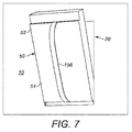
- a single holding portion 156 may be provided as a fabric strap or webbing attached to the backing box and extending from the top to the bottom of the flat panel speaker.
- the opening 20 is dimensioned to substantially correspond to the dimensions of the panel of the speaker unit 54.
- the backing box 52 is dimensioned to be larger than the opening 54 in an axis of the backing box extending in the plane of the mounting surface to enable mounting of the backing box to the rear of the surface, for example by using screw fixings, but is otherwise dimensioned to enable the speaker unit to be passed through the hole into the surface by canting (e.g. by the backing box 52 and speaker unit 50 as a whole being marginally smaller than the opening in another axial direction of the plane of the opening 20).
- the or each holding portion is configured to extend through the hole to allow the pre-assembled speaker 50 to be passed through the opening 20 and held in place flush with the surface 10 of the wall, despite there being only a small gap between the wall 10 in the opening 20 thereof and the edge of the panel of the speaker unit 54.
- a first stage of installing the flat panel speaker 50 in an opening 20 defined in a surface 10 is to pass a region of the backing box 52 in the vicinity of the lower loop strap 56 through a lower portion of the opening 20.
- the height of the backing box 52 is greater than the height of the opening 20.
- the backing box 52 In order for the backing box 52 to be entirely passed through the opening 20, it will be appreciated that the backing box 52 must be passed through the opening 20 at an angle and canted into position.
- FIG 3 is a further illustration of the installation of the flat panel speaker shown in Figure 2 .
- a second stage of installing the flat panel speaker 50 in an opening 20 defined in a surface 10 is to move the backing box 52 vertically downwards, such that a region of the backing box 52 in the vicinity of the upper loop strap 58 can pass through an upper portion of the opening 20.
- An installing user can hold the upper loop strap 58 and the lower loop strap 56 during this process to ensure that the flat panel speaker 50 can be correctly manoeuvred in the opening 20.
- the upper loop strap 58 and the lower loop strap 56 can also be held to keep the flat panel speaker 50 from falling down behind the surface 10.
- FIG 4 is another illustration of the installation of the flat panel speaker shown in Figures 2 and 3 .
- the installing user can use one or both of the upper loop strap 58 and the lower loop strap 56 to hold the flat panel speaker 50 in place in the opening 20 as shown in Figure 4 .
- a contacting surface of the backing box 52 (not visible in Figure 4 ) is held against a back surface of the plasterboard layer (opposite the surface 10).
- the installing user uses the upper loop strap 58 and the lower loop strap 56 to hold the flat panel speaker in place in the opening 20 without having to touch the speaker unit 54, which may be delicate.
- the speaker unit 54 protrudes from the backing box 52 such that, in position, a front surface of the speaker unit 54 is substantially flush with the surface 10. Only a small gap is provided between the speaker unit 54 and the surface 10, such that the speaker unit can be inserted into the opening 20, and the upper loop strap 58 and the lower loop strap 56 can pass through the opening 20 between the surface 10 and the speaker unit 54.
- FIG 5 is yet another illustration of the installation of the flat panel speaker shown in Figures 2 to 4 . Whilst the installing user continues to hold the flat panel speaker 50 in place in the opening 20, the same installing user or a further installing user can secure the flat panel speaker 50 in place in the surface 10.
- a series of mounting holes 62 are provided in the surface 10 above and below the opening 20, formed, for example, by drilling. The mounting holes 62 are positioned within the footprint of the backing box 52. In this way, a corresponding series of mounting screws 60 can pass through the mounting holes 62 of the surface 10 and engage with corresponding holes (not shown) in the backing box 52 to fixedly secure the speaker unit 50 in the opening 20.
- a head portion of each of the mounting screws 60 is configured to be countersunk in the surface so as to not to pass entirely through the mounting holes 62 in order to allow the head portion of the mounting screws 60 to be retained within the plasterboard layer.
- mounting holes 62 and mounting screws 60 to secure the flat panel speaker 50 to the surface 10
- alternative securing techniques will be apparent to the person skilled in the art and can be used.
- one or both of the upper surface of the backing box 52 and the back surface of the plasterboard layer could have one or more adhesive regions to hold the flat panel speaker 50 in place in the opening 20.
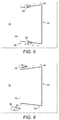
- FIG. 6 is a yet further illustration of the installation of the flat panel speaker shown in Figures 2 to 5 .
- the installing user is no longer required to use the upper loop strap 58 or the lower loop strap 56 to hold the flat panel speaker 50 in place.
- the upper loop strap 58 and the lower loop strap 56 are removed from the installed flat panel speaker 50 by cutting or tearing.
- a knife (not shown) is used to cut the strap at or beneath the level of the opening 20, such that a stub of the upper loop strap 58 or the lower loop strap 56 does not protrude out of the opening 20. It will be appreciated that other ways of removing the upper loop strap 58 or the lower loop strap 56 can be used.
- one or both of the upper loop strap 58 and the lower loop strap 56 may be retractably attached to the backing box 52, such that the straps are configured to be pushed back through the opening so that the straps do not protrude out of the opening 20.
- any securing means such as mounting screws 60 and mounting holes 62 can be painted or plastered over.
- the gap between the surface 10 and the edge of the panel of the speaker unit 54 can be sealed, for example with jointing tape, and the whole surface can be finished with a skim plaster.
- the front surface of the speaker unit 54 can also be finished in substantially the same colour and texture as the surface 10. This ensures that the flat panel speaker 50 is substantially visually indistinguishable as a separate part of the surface 10, such that it is effectively 'invisible'.
Landscapes
- Physics & Mathematics (AREA)
- Engineering & Computer Science (AREA)
- Acoustics & Sound (AREA)
- Signal Processing (AREA)
- Details Of Audible-Bandwidth Transducers (AREA)
- Diaphragms For Electromechanical Transducers (AREA)
Abstract
Description
- This invention relates to a mounting arrangement for a device, such as a flat panel speaker, to be mounted in a surface such as a wall so as to be flush or substantially flush with the surface. The invention relates, in particular, to a flat panel speaker mount.
- It is often desirable to mount devices that would otherwise be taking up space within rooms in the walls or in other surfaces such as ceilings in those rooms so as to be flush with, or substantially not protruding from the surfaces.
- For example, flat panel speakers such as distributed mode loudspeakers or balanced mode radiators provide an apparatus for producing sound which may be mounted flush to a surface of a wall or other structural element of a building, thereby avoiding space from being taken up within the room by a speaker system. To install these devices, typically, a housing or mounting unit is first installed in a hole formed in a wall. A flat panel speaker unit (or other device) is then fitted to the mounting unit after the mounting unit has been installed. This is a particularly elegant solution but there is an ongoing desire to ensure the quality, reliability and integrity of the installed device, and to facilitate the installation method. For example, flat panel speakers can provide high sound quality but this quality is only testable and verifiable only once the speaker unit is correctly fitted to the mounting unit inside the wall. This does not readily enable the assurance of reliable and repeatable performance.
- It is in this context that the present invention is devised.
- Viewed from one aspect, the present invention provides a flat panel speaker configured for mounting in a surface. The flat panel speaker comprises: a mounting unit such as a mounting box for mounting inside the surface, the mounting unit having a front and a back; a speaker unit having a flat panel, wherein the speaker unit is seated in the mounting unit and at least partially extending frontwardly from the front of the mounting unit; and at least one detachable handle affixed to the mounting unit or the speaker unit and arranged for extending frontwardly outwards past the speaker unit and to be usable to hold the flat panel speaker in the surface during mounting.
- Thus, there is provided a holding portion, such as a handle, on a flat panel speaker which can be used when mounting the flat panel speaker to hold the flat panel speaker in position. The detachable handle affixed to the mounting unit or the speaker unit may be affixed to the mounting unit or the speaker unit prior to shipping. In an embodiment, at least a portion of the detachable handle may be removed from the respective mounting unit or speaker unit after mounting the flat panel speaker.
- The handle may be affixed rearwardly of the flat panel and may extend past an outer boundary of the flat panel.
- The handle may comprise a removable portion and a non-removable portion. The removable portion may be configured to be removable from the flat panel speaker. The non-removable portion may be configured to remain affixed to the flat panel speaker when the removable portion is removed.
- The holding portion may be frangibly connected to the flat panel speaker.
- The holding portion may be configured to be removable from the flat panel speaker by at least one of cutting, tearing, snapping or breaking.
- The speaker unit may be arranged to be flush with the surface in use.
- The holding portion may be attached to the flat panel speaker. The holding portion may be attached to the mounting unit.
- The speaker unit may have a footprint smaller than the mounting box in at least one direction along the front of the mounting unit.
- The holding portion may be a strap. The strap may be formed from fabric.
- The mounting box may comprise at least two holding portions.
- Viewed from another aspect, the present invention provides a method of mounting a flat panel speaker in a surface. The flat panel speaker comprises: a mounting unit such as a mounting box for mounting inside the surface and having a front and a back; a speaker unit having a flat panel, wherein the speaker unit is seated in the mounting unit and at least partially extending frontwardly from the front of the mounting unit; and at least one detachable handle affixed to the mounting unit or the speaker unit and arranged for extending frontwardly outwards past the speaker unit and to be usable to hold the flat panel speaker in the surface during mounting. The method comprises: inserting the mounting unit of the flat panel speaker through an opening defined in the surface; using the at least one handle to hold the flat panel speaker in the surface during mounting; and securing the mounting unit to the surface, whereby to hold the flat panel speaker in place in the surface.
- Thus, the holding portion can be used to hold the flat panel speaker in place in the surface during mounting.
- The method may further comprise removing the holding portion from the flat panel speaker.
- The handle may be affixed rearwardly of the flat panel and may extend past an outer boundary of the flat panel.
- The handle may comprise a removable portion and a non-removable portion. The removable portion may be configured to be removable from the flat panel speaker. The non-removable portion may be configured to remain affixed to the flat panel speaker when the removable portion is removed.
- Removing the holding portion may be achieved by at least one of cutting, tearing, snapping or breaking. The at least one of cutting, tearing snapping or breaking the handle may occur at a position rearward of the flat panel.
- The opening may be substantially the same size as a footprint of a speaker unit of the flat panel speaker. The footprint may be in a plane across a front of a mounting unit of the flat panel speaker from which the speaker unit at least partially extends frontwardly. The footprint may be smaller than the mounting unit in at least one direction along the front of the mounting unit.
- The flat panel speaker may comprise at least two holding portions. The method may further comprise removing each of the at least two holding portions from the flat panel speaker by at least one of cutting, tearing, snapping or breaking.
- The opening may be defined by at least one cut through the surface.
- After the mounting box has been secured to the surface, the speaker unit may be arranged to be flush with the surface.
- In accordance with the present invention, a flat panel speaker is provided that is preassembled inside a mounting box and that is provided with removable holding portions that enable the retrofitting of the flat panel speaker through a hole inside a wall or other surface. This simplifies the fitting process as only a single part needs to be installed. This is easily achieved through the holding portion(s) provided on the flat panel speaker. The installer can simply insert the speaker into the cavity in the wall through the hole, and hold the speaker in position using the holding portion(s) while fixing the speaker in place using, for example, screw fixings through the wall or plasterboard. After installation, the holding portions can be removed and discarded and the speaker can be finished by applying a skim or jointing tape to render it invisible. As the speaker unit and mounting unit are pre-assembled, the mounting unit can provide protection for the rear of the speaker unit, and so the speaker unit no longer needs to be provided with a heavy protective casing on its rear surface and its construction can be simplified. In addition, the combination of the mounting unit and speaker unit as a pre-assembled component means that the flat panel speaker can be tested and quality controlled before shipping to allow an assurance of correct installation and operation. Further, the operating parts to the rear of the speaker unit are better isolated from contaminant dust and other damaging materials to which the device is exposed during installation, allowing a greater assurance of reliable and repeatable quality and performance.
- Although the present invention has been described in relation to a flat panel speaker, it will be appreciated that the invention extends to any device mountable in a surface, particularly where the device is to be seated in an opening in the surface, to pass close to the edge of the opening, and particularly where the device is to be substantially flush with the surface. For example, from another aspect, the present invention provides a surface-mountable device configured for mounting in a surface. The surface-mountable device comprises a mounting unit such as a mounting box having a front and a back; a device unit at least partially extending from the front of the mounting unit and having a footprint smaller than the mounting unit in at least one direction along the front of the mounting unit; and at least one handle arranged for extending frontwardly outwards past the device unit. The device unit may be a control panel, for example a switch or a plurality of switches. The device unit may be a display panel, for example an electronic display panel.
- Viewed from another aspect, the present invention provides a method of mounting a surface-mountable device in a surface. The flat surface-mountable device comprises: a mounting unit such as a mounting box for mounting inside the surface and having a front and a back; a device unit seated in the mounting unit and at least partially extending frontwardly from the front of the mounting unit; and at least one holding portion arranged for extending frontwardly outwards past the device unit and to be usable to hold the surface-mountable device in the surface during mounting. The method comprises: inserting the mounting unit through an opening defined in the surface; using the at least one holding portion to hold the surface-mountable device in the surface during mounting; and securing the mounting unit to the surface, whereby to hold the flat panel speaker in place in the surface.
- Furthermore, although the presently described embodiments use at least one handle to be used to hold the flat panel speaker in position against in the surface, it will be appreciated that alternative embodiments are possible where at least one tab is arranged for extending frontwardly outwards past the speaker unit. In this embodiment, the tab may be configured to engage with a further device, wherein the tab and further device, when engaged, form a handle. After the flat panel speaker has been installed, the tab may be removed from the flat panel speaker. In some embodiments, the further device is disengaged from the tab, and the tab is withdrawn back into the flat panel speaker.
- Embodiments of the invention are further described hereinafter with reference to the accompanying drawings, in which:
-
Figure 1 is an illustration of an opening defined in a surface as used for an installation of an embodiment of a flat panel speaker in accordance with the present disclosure; -
Figure 2 is an illustration of an installation of an embodiment of a flat panel speaker in accordance with one embodiment of the present disclosure; -
Figure 3 is a further illustration of the installation of the flat panel speaker shown inFigure 2 ; -
Figure 4 is another illustration of the installation of the flat panel speaker shown inFigures 2 and3 ; -
Figure 5 is yet another illustration of the installation of the flat panel speaker shown inFigures 2 to 4 ; -
Figure 6 is a yet further illustration of the installation of the flat panel speaker shown inFigures 2 to 5 ; -
Figure 7 is an illustration of an installation of another embodiment of a flat panel speaker in accordance with the present disclosure. -
Figure 1 is an illustration of an opening defined in a surface as used for an installation of an embodiment of a flat panel speaker in accordance with the present disclosure. In particular, asurface 10 has defined therein anopening 20. Thesurface 10 is the front surface of a plasterboard layer of a substantially vertical wall. Theopening 20 is defined in thesurface 10 by a series of cuts, resulting in a substantiallyrectangular opening 20 within thesurface 10. Theopening 20 has a horizontal extent of 40 centimetres and a vertical extent of 60 centimetres. - Although embodiments have described the
surface 10 as a plasterboard layer of a substantially vertical wall, in one embodiment, thesurface 10 is the whole thickness of the wall. Thesurface 10 can alternatively be a substantially horizontal surface such as a table or floor or ceiling. In one embodiment, thesurface 10 is a layer of a ceiling, for example a ceiling tile. Although embodiments have described theopening 20 as being defined by a series of cuts, theopening 20 can alternatively be defined by the edges of thesurface 10. Similarly, although embodiments have described theopening 20 as rectangular, it will be appreciated that alternative shapes may be used as required to fit with the shape of the flat panel speaker. -
Figure 2 is an illustration of an installation of an embodiment of a flat panel speaker in accordance with the present disclosure. Aflat panel speaker 50 comprises a mounting unit in the form of abacking box 52. Thebacking box 52 is connected to aspeaker unit 54 which is inserted in and retained by thebacking box 52. Thespeaker unit 54 extends outwardly from a front of thebacking box 52. Thebacking box 52 protects a back surface of thespeaker unit 54. Thespeaker unit 54 is seated in thebacking box 52. Thebacking box 52 has a footprint which is larger than thespeaker unit 54 in one direction. Thebacking box 52 is typically formed from metal. - The
speaker unit 54 comprises a flat panel and operates as a distributed mode loudspeaker. Thespeaker unit 54 is configured to generate sound when vibration modes are induced in the flat panel by an exciter (not shown). Two holding portions are provided on theflat panel speaker 50 in the form of alower loop strap 56 and anupper loop strap 58. Each of thelower loop strap 56 and theupper loop strap 58 is attached to thebacking box 52. Thelower loop strap 56 extends past a bottom edge of thespeaker unit 54. Theupper loop strap 58 extends past a top edge of thespeaker unit 54. Thelower loop strap 56 and theupper loop strap 58 are formed from fabric to ensure they are flexible and are arranged to be able to withstand forces due to the weight of the flat panel speaker and the pulling of the flat panel speaker against the rear of the surface of the wall during mounting. In an alternative embodiment as shown inFigure 7 , asingle holding portion 156 may be provided as a fabric strap or webbing attached to the backing box and extending from the top to the bottom of the flat panel speaker. - The
opening 20 is dimensioned to substantially correspond to the dimensions of the panel of thespeaker unit 54. Thebacking box 52 is dimensioned to be larger than theopening 54 in an axis of the backing box extending in the plane of the mounting surface to enable mounting of the backing box to the rear of the surface, for example by using screw fixings, but is otherwise dimensioned to enable the speaker unit to be passed through the hole into the surface by canting (e.g. by thebacking box 52 andspeaker unit 50 as a whole being marginally smaller than the opening in another axial direction of the plane of the opening 20). - The or each holding portion is configured to extend through the hole to allow the
pre-assembled speaker 50 to be passed through theopening 20 and held in place flush with thesurface 10 of the wall, despite there being only a small gap between thewall 10 in theopening 20 thereof and the edge of the panel of thespeaker unit 54. - As can be seen in
Figure 2 , a first stage of installing theflat panel speaker 50 in anopening 20 defined in asurface 10 is to pass a region of thebacking box 52 in the vicinity of thelower loop strap 56 through a lower portion of theopening 20. The height of thebacking box 52 is greater than the height of theopening 20. In order for thebacking box 52 to be entirely passed through theopening 20, it will be appreciated that thebacking box 52 must be passed through theopening 20 at an angle and canted into position. -
Figure 3 is a further illustration of the installation of the flat panel speaker shown inFigure 2 . As can be seen inFigure 3 , a second stage of installing theflat panel speaker 50 in anopening 20 defined in asurface 10 is to move thebacking box 52 vertically downwards, such that a region of thebacking box 52 in the vicinity of theupper loop strap 58 can pass through an upper portion of theopening 20. An installing user can hold theupper loop strap 58 and thelower loop strap 56 during this process to ensure that theflat panel speaker 50 can be correctly manoeuvred in theopening 20. Theupper loop strap 58 and thelower loop strap 56 can also be held to keep theflat panel speaker 50 from falling down behind thesurface 10. -
Figure 4 is another illustration of the installation of the flat panel speaker shown inFigures 2 and3 . Once theflat panel speaker 50 has been fully passed through theopening 20 as shown inFigure 3 , the installing user can use one or both of theupper loop strap 58 and thelower loop strap 56 to hold theflat panel speaker 50 in place in theopening 20 as shown inFigure 4 . In particular, a contacting surface of the backing box 52 (not visible inFigure 4 ) is held against a back surface of the plasterboard layer (opposite the surface 10). The installing user uses theupper loop strap 58 and thelower loop strap 56 to hold the flat panel speaker in place in theopening 20 without having to touch thespeaker unit 54, which may be delicate. Thespeaker unit 54 protrudes from thebacking box 52 such that, in position, a front surface of thespeaker unit 54 is substantially flush with thesurface 10. Only a small gap is provided between thespeaker unit 54 and thesurface 10, such that the speaker unit can be inserted into theopening 20, and theupper loop strap 58 and thelower loop strap 56 can pass through theopening 20 between thesurface 10 and thespeaker unit 54. -
Figure 5 is yet another illustration of the installation of the flat panel speaker shown inFigures 2 to 4 . Whilst the installing user continues to hold theflat panel speaker 50 in place in theopening 20, the same installing user or a further installing user can secure theflat panel speaker 50 in place in thesurface 10. A series of mountingholes 62 are provided in thesurface 10 above and below theopening 20, formed, for example, by drilling. The mounting holes 62 are positioned within the footprint of thebacking box 52. In this way, a corresponding series of mountingscrews 60 can pass through the mountingholes 62 of thesurface 10 and engage with corresponding holes (not shown) in thebacking box 52 to fixedly secure thespeaker unit 50 in theopening 20. A head portion of each of the mounting screws 60 is configured to be countersunk in the surface so as to not to pass entirely through the mountingholes 62 in order to allow the head portion of the mountingscrews 60 to be retained within the plasterboard layer. - Although the presently described embodiment has used mounting
holes 62 and mountingscrews 60 to secure theflat panel speaker 50 to thesurface 10, it will be appreciated that alternative securing techniques will be apparent to the person skilled in the art and can be used. For example, one or both of the upper surface of thebacking box 52 and the back surface of the plasterboard layer could have one or more adhesive regions to hold theflat panel speaker 50 in place in theopening 20. -
Figure 6 is a yet further illustration of the installation of the flat panel speaker shown inFigures 2 to 5 . After theflat panel speaker 50 has been fixedly secured in theopening 20, the installing user is no longer required to use theupper loop strap 58 or thelower loop strap 56 to hold theflat panel speaker 50 in place. In this particular embodiment, theupper loop strap 58 and thelower loop strap 56 are removed from the installedflat panel speaker 50 by cutting or tearing. For example, a knife (not shown) is used to cut the strap at or beneath the level of theopening 20, such that a stub of theupper loop strap 58 or thelower loop strap 56 does not protrude out of theopening 20. It will be appreciated that other ways of removing theupper loop strap 58 or thelower loop strap 56 can be used. For example, in some embodiments, one or both of theupper loop strap 58 and thelower loop strap 56 may be retractably attached to thebacking box 52, such that the straps are configured to be pushed back through the opening so that the straps do not protrude out of theopening 20. - Once the
flat panel speaker 50 is installed in theopening 20, any securing means such as mountingscrews 60 and mountingholes 62 can be painted or plastered over. The gap between thesurface 10 and the edge of the panel of thespeaker unit 54 can be sealed, for example with jointing tape, and the whole surface can be finished with a skim plaster. The front surface of thespeaker unit 54 can also be finished in substantially the same colour and texture as thesurface 10. This ensures that theflat panel speaker 50 is substantially visually indistinguishable as a separate part of thesurface 10, such that it is effectively 'invisible'. - Throughout the description and claims of this specification, the words "comprise" and "contain" and variations of them mean "including but not limited to", and they are not intended to (and do not) exclude other components, integers or steps. Throughout the description and claims of this specification, the singular encompasses the plural unless the context otherwise requires. In particular, where the indefinite article is used, the specification is to be understood as contemplating plurality as well as singularity, unless the context requires otherwise.
- Features, integers, characteristics or groups described in conjunction with a particular aspect, embodiment or example of the invention are to be understood to be applicable to any other aspect, embodiment or example described herein unless incompatible therewith. All of the features disclosed in this specification (including any accompanying claims, abstract and drawings), and/or all of the steps of any method or process so disclosed, may be combined in any combination, except combinations where at least some of such features and/or steps are mutually exclusive. The invention is not restricted to the details of any foregoing embodiments. The disclosure extends to any novel one, or any novel combination, of the features disclosed in this specification (including any accompanying claims, abstract and drawings), or to any novel one, or any novel combination, of the steps of any method or process so disclosed.
Claims (15)
- A flat panel speaker configured for mounting in a surface, comprising:a mounting unit for mounting inside the surface and having a front and a back;a speaker unit having a flat panel, wherein the speaker unit is seated in the mounting unit and at least partially extending frontwardly from the front of the mounting unit; andat least one detachable handle affixed to the mounting unit or the speaker unit and arranged for extending frontwardly outwards past the speaker unit and to be usable to hold the flat panel speaker in the surface during mounting.
- A flat panel speaker as claimed in claim 1, wherein the handle is affixed rearwardly of the flat panel and extends past an outer boundary of the flat panel.
- A flat panel speaker as claimed in claim 1 or claim 2, wherein the handle comprises a removable portion and a non-removable portion, wherein, the removable portion is configured to be removable from the flat panel speaker and wherein the non-removable portion is configured to remain affixed to the flat panel speaker when the removable portion is removed.
- A flat panel speaker as claimed in any preceding claim, wherein the handle is at least one of:configured to be removable from the flat panel speaker by at least one of cutting, tearing, snapping or breaking;attached to the flat panel speaker, optionally attached to the mounting unit;a strap, optionally wherein the strap is formed from fabric.
- A flat panel speaker as claimed in any preceding claim, wherein the speaker unit is arranged to be flush with the surface in use.
- A flat panel speaker as claimed in any preceding claim, wherein the speaker unit has a footprint smaller than the mounting unit in at least one direction along the front of the mounting unit.
- A flat panel speaker as claimed in any preceding claim, wherein the mounting unit comprises at least two handles.
- A method of mounting a flat panel speaker in a surface, the flat panel speaker comprising:a mounting unit for mounting inside the surface and having a front and a back;a speaker unit having a flat panel, wherein the speaker unit is seated in the mounting unit and at least partially extending frontwardly from the front of the mounting unit; andat least one detachable handle affixed to the mounting unit or the speaker unit and arranged for extending frontwardly outwards past the speaker unit and to be usable to hold the flat panel speaker in the surface during mounting,and the method comprising:inserting the mounting unit of the flat panel speaker through an opening defined in the surface;using the at least one holding portion to hold the flat panel speaker in the surface during mounting; andsecuring the mounting unit to the surface, whereby to hold the flat panel speaker in place in the surface.
- A method as claimed in claim 8, further comprising removing the handle from the flat panel speaker, optionally by at least one of cutting, tearing, snapping or breaking, further optionally by at least one of cutting, tearing snapping or breaking the handle at a position rearward of the flat panel.
- A method as claimed in claim 8 or 9, wherein the handle is affixed rearwardly of the flat panel and extends past an outer boundary of the flat panel.
- A method as claimed in any of claims 8 to 10, wherein the handle comprises a removable portion and a non-removable portion, wherein, the removable portion is configured to be removable from the flat panel speaker and wherein the non-removable portion is configured to remain affixed to the flat panel speaker when the removable portion is removed.
- A method as claimed in any of claims 8 to 11, wherein the opening is substantially the same size as a footprint of a speaker unit of the flat panel speaker, and wherein the footprint is in a plane across a front of a mounting unit of the flat panel speaker from which the speaker unit at least partially extends frontwardly, and wherein the footprint is smaller than the mounting unit in at least one direction along the front of the mounting unit.
- A method as claimed in any of claims 8 to 12, wherein the flat panel speaker comprises at least two handles, and wherein the method comprises removing each of the at least two handles from the flat panel speaker by at least one of cutting, tearing, snapping or breaking.
- A method as claimed in any of claims 8 to 13, wherein the opening is defined by at least one cut through the surface.
- A method as claimed in any of claims 8 to 14, wherein after the mounting unit has been secured to the surface, the speaker unit is arranged to be flush with the surface.
Priority Applications (1)
| Application Number | Priority Date | Filing Date | Title |
|---|---|---|---|
| CN201610375255.5A CN107306365B (en) | 2015-04-20 | 2016-05-31 | Mounting member and mounting method for flat panel speaker or other device |
Applications Claiming Priority (1)
| Application Number | Priority Date | Filing Date | Title |
|---|---|---|---|
| GB1506659.0A GB2537617B (en) | 2015-04-20 | 2015-04-20 | Flat panel speaker or other device mount and installation method |
Publications (2)
| Publication Number | Publication Date |
|---|---|
| EP3086564A1 true EP3086564A1 (en) | 2016-10-26 |
| EP3086564B1 EP3086564B1 (en) | 2022-11-30 |
Family
ID=53298841
Family Applications (1)
| Application Number | Title | Priority Date | Filing Date |
|---|---|---|---|
| EP16166078.2A Active EP3086564B1 (en) | 2015-04-20 | 2016-04-19 | Flat panel speaker mount |
Country Status (5)
| Country | Link |
|---|---|
| US (1) | US9807482B2 (en) |
| EP (1) | EP3086564B1 (en) |
| CN (1) | CN107306365B (en) |
| ES (1) | ES2935064T3 (en) |
| GB (1) | GB2537617B (en) |
Cited By (1)
| Publication number | Priority date | Publication date | Assignee | Title |
|---|---|---|---|---|
| BE1027104B1 (en) * | 2019-03-08 | 2020-10-05 | Apart Audio Nv | Combination of a loudspeaker box and a suspension bracket for hanging the loudspeaker box |
Families Citing this family (6)
| Publication number | Priority date | Publication date | Assignee | Title |
|---|---|---|---|---|
| US9877112B2 (en) * | 2016-03-29 | 2018-01-23 | Dell Products L.P. | Piezoelectric force actuator audio system |
| GB2551723B (en) * | 2016-06-27 | 2018-11-28 | Amina Tech Limited | Speaker Panel |
| GB2560878B (en) * | 2017-02-24 | 2021-10-27 | Google Llc | A panel loudspeaker controller and a panel loudspeaker |
| CN112585994B (en) * | 2018-06-07 | 2023-01-20 | 阿米那科技有限公司 | Front-mounted flat panel speaker assembly |
| US12572319B2 (en) * | 2022-08-01 | 2026-03-10 | Crestron Electronics, Inc. | System and method for playing an audio indicator to identify a location of a ceiling mounted loudspeaker |
| EP4518346A1 (en) | 2023-08-29 | 2025-03-05 | UAB The Invisible Loudspeaker Company | A flat panel loudspeaker chassis and method for installing a flat panel loudspeaker |
Citations (7)
| Publication number | Priority date | Publication date | Assignee | Title |
|---|---|---|---|---|
| US4179009A (en) * | 1977-03-15 | 1979-12-18 | Blaupunkt-Werke Gmbh | Mounting arrangement for a loudspeaker to a resonance panel permitting front insertion assembly |
| EP1185134A2 (en) * | 2000-08-30 | 2002-03-06 | Armstrong World Industries, Inc. | Facing system for a flat panel radiator |
| US7563989B1 (en) * | 2005-04-08 | 2009-07-21 | Robert Louis Fils | Mounting bracket |
| US20090193724A1 (en) * | 2006-09-11 | 2009-08-06 | Scott Struthers | Flush Mounting Apparatus And Methods Using Component Cover |
| US20100133863A1 (en) * | 2008-12-01 | 2010-06-03 | Po-Lin Liao | Stepwise powerful suction device |
| US8157306B1 (en) * | 2009-03-12 | 2012-04-17 | Professional Engineering Co., Inc. | Device for installing and removing ceiling panels |
| US20140294540A1 (en) * | 2013-04-02 | 2014-10-02 | Snap-On Incorporated | Panel Hoist |
Family Cites Families (17)
| Publication number | Priority date | Publication date | Assignee | Title |
|---|---|---|---|---|
| DE19612080A1 (en) * | 1996-03-27 | 1997-10-02 | Nokia Deutschland Gmbh | speaker |
| US6092705A (en) * | 1998-08-03 | 2000-07-25 | Meritt; Ronald R. | Self-contained case for housing transporting and mounting video monitor and video player for use in passenger vehicles |
| US6986447B2 (en) * | 2003-06-05 | 2006-01-17 | Motion Systems, Llc | Television tote bag |
| US20070064964A1 (en) * | 2005-09-16 | 2007-03-22 | Cheung Kwun-Wing W | Flat panel speaker assembly |
| EP1841304A1 (en) * | 2006-03-31 | 2007-10-03 | Barco N.V. | A flat panel display wall |
| US8209921B2 (en) * | 2006-09-11 | 2012-07-03 | Dana Innovations | Flush mount panels with multiple aligned receiving brackets |
| US20090249705A1 (en) * | 2006-12-04 | 2009-10-08 | Trufig | Mounting Receivers with Spackling Rim Gradient |
| JP5070840B2 (en) * | 2006-12-29 | 2012-11-14 | ソニー株式会社 | Display device with speaker |
| CN201323649Y (en) * | 2008-11-12 | 2009-10-07 | 陈进 | Suction-disc flat speaker |
| US8720846B2 (en) * | 2009-07-03 | 2014-05-13 | Milestone Av Technologies Llc | Television safety strap |
| US8955197B2 (en) * | 2011-12-13 | 2015-02-17 | Kelly R. Bailey | Detachable grab handle |
| DE102012204407B4 (en) * | 2012-03-20 | 2024-08-01 | Robert Bosch Gmbh | System with at least a hand tool case and a construction site radio |
| JP5906951B2 (en) * | 2012-06-11 | 2016-04-20 | ヤマハ株式会社 | Speaker unit |
| WO2014045350A1 (en) * | 2012-09-19 | 2014-03-27 | Necディスプレイソリューションズ株式会社 | Handle and display device provided with same |
| CN103713712A (en) * | 2013-12-20 | 2014-04-09 | 晟扬精密模具(昆山)有限公司 | Tablet personal computer rear cover |
| US9271584B1 (en) * | 2014-08-29 | 2016-03-01 | Specialty Store Services, Inc. | Portable display stand having foldable one-piece vertical support panel that is capable of tool-free assembly and disassembly |
| US20160157001A1 (en) * | 2014-11-27 | 2016-06-02 | Christopher Manouel | Wireless Speaker Enclsoure |
-
2015
- 2015-04-20 GB GB1506659.0A patent/GB2537617B/en active Active
-
2016
- 2016-04-19 ES ES16166078T patent/ES2935064T3/en active Active
- 2016-04-19 EP EP16166078.2A patent/EP3086564B1/en active Active
- 2016-04-20 US US15/134,141 patent/US9807482B2/en active Active
- 2016-05-31 CN CN201610375255.5A patent/CN107306365B/en active Active
Patent Citations (7)
| Publication number | Priority date | Publication date | Assignee | Title |
|---|---|---|---|---|
| US4179009A (en) * | 1977-03-15 | 1979-12-18 | Blaupunkt-Werke Gmbh | Mounting arrangement for a loudspeaker to a resonance panel permitting front insertion assembly |
| EP1185134A2 (en) * | 2000-08-30 | 2002-03-06 | Armstrong World Industries, Inc. | Facing system for a flat panel radiator |
| US7563989B1 (en) * | 2005-04-08 | 2009-07-21 | Robert Louis Fils | Mounting bracket |
| US20090193724A1 (en) * | 2006-09-11 | 2009-08-06 | Scott Struthers | Flush Mounting Apparatus And Methods Using Component Cover |
| US20100133863A1 (en) * | 2008-12-01 | 2010-06-03 | Po-Lin Liao | Stepwise powerful suction device |
| US8157306B1 (en) * | 2009-03-12 | 2012-04-17 | Professional Engineering Co., Inc. | Device for installing and removing ceiling panels |
| US20140294540A1 (en) * | 2013-04-02 | 2014-10-02 | Snap-On Incorporated | Panel Hoist |
Cited By (1)
| Publication number | Priority date | Publication date | Assignee | Title |
|---|---|---|---|---|
| BE1027104B1 (en) * | 2019-03-08 | 2020-10-05 | Apart Audio Nv | Combination of a loudspeaker box and a suspension bracket for hanging the loudspeaker box |
Also Published As
| Publication number | Publication date |
|---|---|
| GB201506659D0 (en) | 2015-06-03 |
| CN107306365B (en) | 2021-03-12 |
| ES2935064T3 (en) | 2023-03-01 |
| US9807482B2 (en) | 2017-10-31 |
| EP3086564B1 (en) | 2022-11-30 |
| GB2537617A (en) | 2016-10-26 |
| CN107306365A (en) | 2017-10-31 |
| GB2537617B (en) | 2018-08-01 |
| US20160309247A1 (en) | 2016-10-20 |
Similar Documents
| Publication | Publication Date | Title |
|---|---|---|
| US9807482B2 (en) | Flat panel speaker or other device mount and installation method | |
| US8245453B2 (en) | Flush mounting apparatus and methods using component cover | |
| US8209921B2 (en) | Flush mount panels with multiple aligned receiving brackets | |
| CA2819077C (en) | Adjustable bracket for steel stud | |
| US6931794B1 (en) | Method and apparatus for installing fitting | |
| US10856675B2 (en) | Picture frame hanging assembly and method of installation | |
| CA2568122A1 (en) | Mounting clips for siding boards | |
| US20160273797A1 (en) | Dry wall extrusion grille frame | |
| CN107428496B (en) | elevator operating panel | |
| WO2010028221A3 (en) | Universal back box for mounting in wall components and method of use | |
| US20110067320A1 (en) | Wall-Mount Adjustment Systems And Methods | |
| US20210131698A1 (en) | Dry wall extrusion grille frame with seismic tether | |
| CA2606647A1 (en) | Installation bracket for electrical box, electrical box assembly, and method of use | |
| US8079842B1 (en) | Plaster removing device | |
| EP2736138B1 (en) | Box for installing and wiring electrical devices | |
| US20180062366A1 (en) | Enclosed Housing for Alarm System Electrical Equipment | |
| US7963076B2 (en) | Devices and methods for flangeless installations | |
| EP2754770A1 (en) | Construction panel for installation on a framework | |
| AU2018204298B2 (en) | Housing for an electrical fitting in a sliding door unit | |
| EP3207606B1 (en) | Wall-mounted electrical housing | |
| AU771072B2 (en) | Method and apparatus for installing a fitting | |
| GB2440184A (en) | Electrical accessory box comprising stop member | |
| JP5769949B2 (en) | Instrument mounting body | |
| CA2665919A1 (en) | Frame for mounting in a wall structure | |
| JP2007039964A (en) | Device for mounting cladding material on skeleton |
Legal Events
| Date | Code | Title | Description |
|---|---|---|---|
| PUAI | Public reference made under article 153(3) epc to a published international application that has entered the european phase |
Free format text: ORIGINAL CODE: 0009012 |
|
| AK | Designated contracting states |
Kind code of ref document: A1 Designated state(s): AL AT BE BG CH CY CZ DE DK EE ES FI FR GB GR HR HU IE IS IT LI LT LU LV MC MK MT NL NO PL PT RO RS SE SI SK SM TR |
|
| AX | Request for extension of the european patent |
Extension state: BA ME |
|
| 17P | Request for examination filed |
Effective date: 20170426 |
|
| RBV | Designated contracting states (corrected) |
Designated state(s): AL AT BE BG CH CY CZ DE DK EE ES FI FR GB GR HR HU IE IS IT LI LT LU LV MC MK MT NL NO PL PT RO RS SE SI SK SM TR |
|
| STAA | Information on the status of an ep patent application or granted ep patent |
Free format text: STATUS: REQUEST FOR EXAMINATION WAS MADE |
|
| STAA | Information on the status of an ep patent application or granted ep patent |
Free format text: STATUS: EXAMINATION IS IN PROGRESS |
|
| 17Q | First examination report despatched |
Effective date: 20190201 |
|
| GRAP | Despatch of communication of intention to grant a patent |
Free format text: ORIGINAL CODE: EPIDOSNIGR1 |
|
| STAA | Information on the status of an ep patent application or granted ep patent |
Free format text: STATUS: GRANT OF PATENT IS INTENDED |
|
| INTG | Intention to grant announced |
Effective date: 20220704 |
|
| GRAS | Grant fee paid |
Free format text: ORIGINAL CODE: EPIDOSNIGR3 |
|
| GRAA | (expected) grant |
Free format text: ORIGINAL CODE: 0009210 |
|
| STAA | Information on the status of an ep patent application or granted ep patent |
Free format text: STATUS: THE PATENT HAS BEEN GRANTED |
|
| RBV | Designated contracting states (corrected) |
Designated state(s): AL AT BE BG CH CY CZ DE DK EE ES FI FR GR HR HU IE IS IT LI LT LU LV MC MK MT NL NO PL PT RO RS SE SI SK SM TR |
|
| AK | Designated contracting states |
Kind code of ref document: B1 Designated state(s): AL AT BE BG CH CY CZ DE DK EE ES FI FR GR HR HU IE IS IT LI LT LU LV MC MK MT NL NO PL PT RO RS SE SI SK SM TR |
|
| REG | Reference to a national code |
Ref country code: CH Ref legal event code: EP |
|
| REG | Reference to a national code |
Ref country code: AT Ref legal event code: REF Ref document number: 1535615 Country of ref document: AT Kind code of ref document: T Effective date: 20221215 Ref country code: DE Ref legal event code: R096 Ref document number: 602016076564 Country of ref document: DE |
|
| REG | Reference to a national code |
Ref country code: IE Ref legal event code: FG4D |
|
| REG | Reference to a national code |
Ref country code: ES Ref legal event code: FG2A Ref document number: 2935064 Country of ref document: ES Kind code of ref document: T3 Effective date: 20230301 |
|
| REG | Reference to a national code |
Ref country code: LT Ref legal event code: MG9D |
|
| REG | Reference to a national code |
Ref country code: NL Ref legal event code: MP Effective date: 20221130 |
|
| PG25 | Lapsed in a contracting state [announced via postgrant information from national office to epo] |
Ref country code: SE Free format text: LAPSE BECAUSE OF FAILURE TO SUBMIT A TRANSLATION OF THE DESCRIPTION OR TO PAY THE FEE WITHIN THE PRESCRIBED TIME-LIMIT Effective date: 20221130 Ref country code: PT Free format text: LAPSE BECAUSE OF FAILURE TO SUBMIT A TRANSLATION OF THE DESCRIPTION OR TO PAY THE FEE WITHIN THE PRESCRIBED TIME-LIMIT Effective date: 20230331 Ref country code: NO Free format text: LAPSE BECAUSE OF FAILURE TO SUBMIT A TRANSLATION OF THE DESCRIPTION OR TO PAY THE FEE WITHIN THE PRESCRIBED TIME-LIMIT Effective date: 20230228 Ref country code: LT Free format text: LAPSE BECAUSE OF FAILURE TO SUBMIT A TRANSLATION OF THE DESCRIPTION OR TO PAY THE FEE WITHIN THE PRESCRIBED TIME-LIMIT Effective date: 20221130 Ref country code: FI Free format text: LAPSE BECAUSE OF FAILURE TO SUBMIT A TRANSLATION OF THE DESCRIPTION OR TO PAY THE FEE WITHIN THE PRESCRIBED TIME-LIMIT Effective date: 20221130 |
|
| REG | Reference to a national code |
Ref country code: AT Ref legal event code: MK05 Ref document number: 1535615 Country of ref document: AT Kind code of ref document: T Effective date: 20221130 |
|
| PG25 | Lapsed in a contracting state [announced via postgrant information from national office to epo] |
Ref country code: RS Free format text: LAPSE BECAUSE OF FAILURE TO SUBMIT A TRANSLATION OF THE DESCRIPTION OR TO PAY THE FEE WITHIN THE PRESCRIBED TIME-LIMIT Effective date: 20221130 Ref country code: PL Free format text: LAPSE BECAUSE OF FAILURE TO SUBMIT A TRANSLATION OF THE DESCRIPTION OR TO PAY THE FEE WITHIN THE PRESCRIBED TIME-LIMIT Effective date: 20221130 Ref country code: LV Free format text: LAPSE BECAUSE OF FAILURE TO SUBMIT A TRANSLATION OF THE DESCRIPTION OR TO PAY THE FEE WITHIN THE PRESCRIBED TIME-LIMIT Effective date: 20221130 Ref country code: IS Free format text: LAPSE BECAUSE OF FAILURE TO SUBMIT A TRANSLATION OF THE DESCRIPTION OR TO PAY THE FEE WITHIN THE PRESCRIBED TIME-LIMIT Effective date: 20230330 Ref country code: HR Free format text: LAPSE BECAUSE OF FAILURE TO SUBMIT A TRANSLATION OF THE DESCRIPTION OR TO PAY THE FEE WITHIN THE PRESCRIBED TIME-LIMIT Effective date: 20221130 Ref country code: GR Free format text: LAPSE BECAUSE OF FAILURE TO SUBMIT A TRANSLATION OF THE DESCRIPTION OR TO PAY THE FEE WITHIN THE PRESCRIBED TIME-LIMIT Effective date: 20230301 |
|
| PG25 | Lapsed in a contracting state [announced via postgrant information from national office to epo] |
Ref country code: NL Free format text: LAPSE BECAUSE OF FAILURE TO SUBMIT A TRANSLATION OF THE DESCRIPTION OR TO PAY THE FEE WITHIN THE PRESCRIBED TIME-LIMIT Effective date: 20221130 |
|
| PG25 | Lapsed in a contracting state [announced via postgrant information from national office to epo] |
Ref country code: SM Free format text: LAPSE BECAUSE OF FAILURE TO SUBMIT A TRANSLATION OF THE DESCRIPTION OR TO PAY THE FEE WITHIN THE PRESCRIBED TIME-LIMIT Effective date: 20221130 Ref country code: RO Free format text: LAPSE BECAUSE OF FAILURE TO SUBMIT A TRANSLATION OF THE DESCRIPTION OR TO PAY THE FEE WITHIN THE PRESCRIBED TIME-LIMIT Effective date: 20221130 Ref country code: EE Free format text: LAPSE BECAUSE OF FAILURE TO SUBMIT A TRANSLATION OF THE DESCRIPTION OR TO PAY THE FEE WITHIN THE PRESCRIBED TIME-LIMIT Effective date: 20221130 Ref country code: DK Free format text: LAPSE BECAUSE OF FAILURE TO SUBMIT A TRANSLATION OF THE DESCRIPTION OR TO PAY THE FEE WITHIN THE PRESCRIBED TIME-LIMIT Effective date: 20221130 Ref country code: CZ Free format text: LAPSE BECAUSE OF FAILURE TO SUBMIT A TRANSLATION OF THE DESCRIPTION OR TO PAY THE FEE WITHIN THE PRESCRIBED TIME-LIMIT Effective date: 20221130 Ref country code: AT Free format text: LAPSE BECAUSE OF FAILURE TO SUBMIT A TRANSLATION OF THE DESCRIPTION OR TO PAY THE FEE WITHIN THE PRESCRIBED TIME-LIMIT Effective date: 20221130 |
|
| PG25 | Lapsed in a contracting state [announced via postgrant information from national office to epo] |
Ref country code: SK Free format text: LAPSE BECAUSE OF FAILURE TO SUBMIT A TRANSLATION OF THE DESCRIPTION OR TO PAY THE FEE WITHIN THE PRESCRIBED TIME-LIMIT Effective date: 20221130 Ref country code: AL Free format text: LAPSE BECAUSE OF FAILURE TO SUBMIT A TRANSLATION OF THE DESCRIPTION OR TO PAY THE FEE WITHIN THE PRESCRIBED TIME-LIMIT Effective date: 20221130 |
|
| REG | Reference to a national code |
Ref country code: DE Ref legal event code: R097 Ref document number: 602016076564 Country of ref document: DE |
|
| PLBE | No opposition filed within time limit |
Free format text: ORIGINAL CODE: 0009261 |
|
| STAA | Information on the status of an ep patent application or granted ep patent |
Free format text: STATUS: NO OPPOSITION FILED WITHIN TIME LIMIT |
|
| REG | Reference to a national code |
Ref country code: DE Ref legal event code: R119 Ref document number: 602016076564 Country of ref document: DE |
|
| 26N | No opposition filed |
Effective date: 20230831 |
|
| PG25 | Lapsed in a contracting state [announced via postgrant information from national office to epo] |
Ref country code: SI Free format text: LAPSE BECAUSE OF FAILURE TO SUBMIT A TRANSLATION OF THE DESCRIPTION OR TO PAY THE FEE WITHIN THE PRESCRIBED TIME-LIMIT Effective date: 20221130 |
|
| REG | Reference to a national code |
Ref country code: CH Ref legal event code: PL |
|
| PG25 | Lapsed in a contracting state [announced via postgrant information from national office to epo] |
Ref country code: LU Free format text: LAPSE BECAUSE OF NON-PAYMENT OF DUE FEES Effective date: 20230419 |
|
| REG | Reference to a national code |
Ref country code: BE Ref legal event code: MM Effective date: 20230430 |
|
| PG25 | Lapsed in a contracting state [announced via postgrant information from national office to epo] |
Ref country code: MC Free format text: LAPSE BECAUSE OF FAILURE TO SUBMIT A TRANSLATION OF THE DESCRIPTION OR TO PAY THE FEE WITHIN THE PRESCRIBED TIME-LIMIT Effective date: 20221130 |
|
| PG25 | Lapsed in a contracting state [announced via postgrant information from national office to epo] |
Ref country code: MC Free format text: LAPSE BECAUSE OF FAILURE TO SUBMIT A TRANSLATION OF THE DESCRIPTION OR TO PAY THE FEE WITHIN THE PRESCRIBED TIME-LIMIT Effective date: 20221130 Ref country code: LI Free format text: LAPSE BECAUSE OF NON-PAYMENT OF DUE FEES Effective date: 20230430 Ref country code: FR Free format text: LAPSE BECAUSE OF NON-PAYMENT OF DUE FEES Effective date: 20230430 Ref country code: DE Free format text: LAPSE BECAUSE OF NON-PAYMENT OF DUE FEES Effective date: 20231103 Ref country code: CH Free format text: LAPSE BECAUSE OF NON-PAYMENT OF DUE FEES Effective date: 20230430 |
|
| REG | Reference to a national code |
Ref country code: IE Ref legal event code: MM4A |
|
| PG25 | Lapsed in a contracting state [announced via postgrant information from national office to epo] |
Ref country code: BE Free format text: LAPSE BECAUSE OF NON-PAYMENT OF DUE FEES Effective date: 20230430 |
|
| PG25 | Lapsed in a contracting state [announced via postgrant information from national office to epo] |
Ref country code: IE Free format text: LAPSE BECAUSE OF NON-PAYMENT OF DUE FEES Effective date: 20230419 |
|
| PG25 | Lapsed in a contracting state [announced via postgrant information from national office to epo] |
Ref country code: IE Free format text: LAPSE BECAUSE OF NON-PAYMENT OF DUE FEES Effective date: 20230419 |
|
| PG25 | Lapsed in a contracting state [announced via postgrant information from national office to epo] |
Ref country code: BG Free format text: LAPSE BECAUSE OF FAILURE TO SUBMIT A TRANSLATION OF THE DESCRIPTION OR TO PAY THE FEE WITHIN THE PRESCRIBED TIME-LIMIT Effective date: 20221130 |
|
| PG25 | Lapsed in a contracting state [announced via postgrant information from national office to epo] |
Ref country code: BG Free format text: LAPSE BECAUSE OF FAILURE TO SUBMIT A TRANSLATION OF THE DESCRIPTION OR TO PAY THE FEE WITHIN THE PRESCRIBED TIME-LIMIT Effective date: 20221130 |
|
| PG25 | Lapsed in a contracting state [announced via postgrant information from national office to epo] |
Ref country code: CY Free format text: LAPSE BECAUSE OF FAILURE TO SUBMIT A TRANSLATION OF THE DESCRIPTION OR TO PAY THE FEE WITHIN THE PRESCRIBED TIME-LIMIT; INVALID AB INITIO Effective date: 20160419 |
|
| PG25 | Lapsed in a contracting state [announced via postgrant information from national office to epo] |
Ref country code: HU Free format text: LAPSE BECAUSE OF FAILURE TO SUBMIT A TRANSLATION OF THE DESCRIPTION OR TO PAY THE FEE WITHIN THE PRESCRIBED TIME-LIMIT; INVALID AB INITIO Effective date: 20160419 |
|
| PG25 | Lapsed in a contracting state [announced via postgrant information from national office to epo] |
Ref country code: TR Free format text: LAPSE BECAUSE OF FAILURE TO SUBMIT A TRANSLATION OF THE DESCRIPTION OR TO PAY THE FEE WITHIN THE PRESCRIBED TIME-LIMIT Effective date: 20221130 |
|
| PGFP | Annual fee paid to national office [announced via postgrant information from national office to epo] |
Ref country code: ES Payment date: 20260512 Year of fee payment: 11 |
|
| PGFP | Annual fee paid to national office [announced via postgrant information from national office to epo] |
Ref country code: IT Payment date: 20260417 Year of fee payment: 11 |