EP3086507A1 - Method for operating a distribution point unit, respective distribution point unit and cpe device - Google Patents
Method for operating a distribution point unit, respective distribution point unit and cpe device Download PDFInfo
- Publication number
- EP3086507A1 EP3086507A1 EP15305629.6A EP15305629A EP3086507A1 EP 3086507 A1 EP3086507 A1 EP 3086507A1 EP 15305629 A EP15305629 A EP 15305629A EP 3086507 A1 EP3086507 A1 EP 3086507A1
- Authority
- EP
- European Patent Office
- Prior art keywords
- service
- dpu
- selection switch
- switch
- monitor
- Prior art date
- Legal status (The legal status is an assumption and is not a legal conclusion. Google has not performed a legal analysis and makes no representation as to the accuracy of the status listed.)
- Withdrawn
Links
- 238000000034 method Methods 0.000 title claims abstract description 19
- RYGMFSIKBFXOCR-UHFFFAOYSA-N Copper Chemical compound [Cu] RYGMFSIKBFXOCR-UHFFFAOYSA-N 0.000 claims description 35
- 229910052802 copper Inorganic materials 0.000 claims description 28
- 239000010949 copper Substances 0.000 claims description 28
- 239000000835 fiber Substances 0.000 description 5
- 238000005516 engineering process Methods 0.000 description 4
- 230000005012 migration Effects 0.000 description 4
- 238000013508 migration Methods 0.000 description 4
- 230000004913 activation Effects 0.000 description 2
- 239000013307 optical fiber Substances 0.000 description 2
- 230000005540 biological transmission Effects 0.000 description 1
- 230000009977 dual effect Effects 0.000 description 1
- 238000009434 installation Methods 0.000 description 1
- 230000003287 optical effect Effects 0.000 description 1
- 238000011144 upstream manufacturing Methods 0.000 description 1
Images



Classifications
-
- H—ELECTRICITY
- H04—ELECTRIC COMMUNICATION TECHNIQUE
- H04L—TRANSMISSION OF DIGITAL INFORMATION, e.g. TELEGRAPHIC COMMUNICATION
- H04L12/00—Data switching networks
- H04L12/28—Data switching networks characterised by path configuration, e.g. LAN [Local Area Networks] or WAN [Wide Area Networks]
- H04L12/2854—Wide area networks, e.g. public data networks
- H04L12/2856—Access arrangements, e.g. Internet access
- H04L12/2869—Operational details of access network equipments
-
- H—ELECTRICITY
- H04—ELECTRIC COMMUNICATION TECHNIQUE
- H04L—TRANSMISSION OF DIGITAL INFORMATION, e.g. TELEGRAPHIC COMMUNICATION
- H04L12/00—Data switching networks
- H04L12/02—Details
- H04L12/10—Current supply arrangements
-
- H—ELECTRICITY
- H04—ELECTRIC COMMUNICATION TECHNIQUE
- H04L—TRANSMISSION OF DIGITAL INFORMATION, e.g. TELEGRAPHIC COMMUNICATION
- H04L12/00—Data switching networks
- H04L12/28—Data switching networks characterised by path configuration, e.g. LAN [Local Area Networks] or WAN [Wide Area Networks]
- H04L12/40—Bus networks
- H04L12/40006—Architecture of a communication node
- H04L12/40045—Details regarding the feeding of energy to the node from the bus
-
- H—ELECTRICITY
- H04—ELECTRIC COMMUNICATION TECHNIQUE
- H04M—TELEPHONIC COMMUNICATION
- H04M11/00—Telephonic communication systems specially adapted for combination with other electrical systems
- H04M11/06—Simultaneous speech and data transmission, e.g. telegraphic transmission over the same conductors
- H04M11/062—Simultaneous speech and data transmission, e.g. telegraphic transmission over the same conductors using different frequency bands for speech and other data
-
- H—ELECTRICITY
- H04—ELECTRIC COMMUNICATION TECHNIQUE
- H04M—TELEPHONIC COMMUNICATION
- H04M19/00—Current supply arrangements for telephone systems
- H04M19/08—Current supply arrangements for telephone systems with current supply sources at the substations
-
- H—ELECTRICITY
- H04—ELECTRIC COMMUNICATION TECHNIQUE
- H04L—TRANSMISSION OF DIGITAL INFORMATION, e.g. TELEGRAPHIC COMMUNICATION
- H04L12/00—Data switching networks
- H04L12/28—Data switching networks characterised by path configuration, e.g. LAN [Local Area Networks] or WAN [Wide Area Networks]
- H04L12/2854—Wide area networks, e.g. public data networks
- H04L12/2856—Access arrangements, e.g. Internet access
- H04L12/2869—Operational details of access network equipments
- H04L12/2898—Subscriber equipments
Definitions
- the present disclosure relates to the field of customer premises equipment devices being coupled via a digital subscriber line to a service provider delivering broadband services to a customer.
- US 8,601,289 discloses an optical network comprising a DPU and a plurality of CPE devices, each CPE device having a reverse power supply and each being connected to a copper wire pair and configured to transmit and receive data and provide reverse power over the wire pair.
- a power management circuit of the DPU is provided being configured to receive power and to provide power sharing and manage power consumption and power supply redundancy from the plurality of CPE devices.
- the DPU includes in a preferred embodiment a controller, e.g. a microprocessor, a memory for the operation of the DPU and in which an operating system is stored, a power supply for receiving supply power from a CPE device and for powering the DPU, a port for an optical fiber connection, e.g. with a central office, and two ports for copper lines, in particular for copper wire pairs.
- the DPU may include in particular a multitude of G.fast channels for providing the G.fast service to a multitude of CPE devices located in a the homes of customers.
- the monitor and control logic 15 When the xDSL and PSTN services are in operation and the monitor and control logic 15 detects switching pulses of the AGW drive logic 21 on the copper line 7, it switches the selection switch 17 via the switch drive logic 16 to the broadband analog front end 14 and to the DPU power supply unit 13 for enabling the G.fast service.
- the DPU 10 includes further a DPU drive logic 12 being coupled with the switch drive logic 16, via which the selection switch 17 is kept in the G.fast selection mode, when a reverse supply power is provided by the AGW 20 and the DPU control pulses are switched off by the AGW 20.
- step 60 the DPU 10 and the AGW 20 are off and in a default state, in which the selection switch 17 is switched to the xDSL and PSTN services.
- step 62 the AGW 20 detects that the xDSL and the PSTN services are connected via the copper lines 6 and 7.
- the reverse power supply 22 remains switched off.
- the service switch 26 is in a default state connecting the copper line 7 with the low pass filter 25.
- the AGW 20 then checks whether an xDSL service is available, detectable by the broadband analog front end 23, and/or a PSTN service is available, detectable by the FXO circuit 24. Is an xDSL service or a PSTN service detected, the respective service is enabled and provided by the AGW 20 to the customer, step 66, which is indicated on the AGW 20 by indicator lights, not shown.
Landscapes
- Engineering & Computer Science (AREA)
- Signal Processing (AREA)
- Computer Networks & Wireless Communication (AREA)
- Telephonic Communication Services (AREA)
- Exchange Systems With Centralized Control (AREA)
Abstract
The method for operating a distribution point unit comprising a selection switch (17) and a monitor and control logic (15) for providing a first and a second service, comprises the steps of: receiving a switching signal powering the monitor and control logic (68), and switching the selection switch from the first service to the second service by the monitor and control logic (70), after receiving the switching signal. The selection switch has a default state, in which the first service is provided. The first service is in particular an xDSL and/or a PSTN service, and the second service is a G.fast service.
Description
- The present disclosure relates to the field of customer premises equipment devices being coupled via a digital subscriber line to a service provider delivering broadband services to a customer.
- Access gateways are widely used to connect devices in a home of a customer to the Internet or any other wide area network (WAN). Access gateways use for example digital subscriber line (DSL) technology that enables a high data rate transmission over copper lines. During the years, several DSL standards have been established differing in data rates and in range, for example ADSL (Asymmetric digital subscriber line), ADSL2, VDSL (Very High Speed Digital Subscriber Line) and VDSL2, which are referred to in this context as xDSL. Network operators, e.g. Internet service providers, are managing a large amount, up to millions, of residential gateways, also other devices such as routers, switches, telephones and set-top boxes, which are understood in this context as customer premises equipment (CPE) devices.
- Fiber to the distribution point (FTTdp) is bringing the fiber optic connection of the service providers closer to the home of the customer. However, the last few 100 meters of the broadband connection are still handled by the existing copper wire to the home: currently being used for legacy technologies such as Public Switched Telephone Network (PSTN) and xDSL.
- In order to match the increased speed capabilities that come with bringing the fiber nodes closer to the home, the technology on the copper wire is also evolving to higher speeds. This is the base for the introduction of G.fast as an improved access technology on the copper wire. Formal specifications for G.fast have been drafted as ITU-T G.9700 and G.9701.
-
Figure 1 shows the migration from copper links to fiber links closer to the home. For G.fast, a Distribution Point Unit (DPU) provides the link between the optical fiber of the Central Office (CO) with the CPE of the customer. In order to enable a flexible deployment of the DPU close to the home of the customer, the G.fast standardization foresees reverse power feeding for the DPU. In this scenario, the DPU is powered by the CPE, or a separate power injector located at the customer's premises. This enables a flexible placement of the DPU and allows for multiple subscribers to provide power for a DPU. - The benefits of using reverse power feeding lie mainly in flexibility and cost advantages, but several challenges arise. There are safety requirements that need to be met, for example since power is running on the telephone wires, a user might be exposed, or old legacy equipment that might still be connected to the telephone wire might be damaged by this power. Other important aspects to be considered are that the CPE devices can be located at different ranges from the DPU and each cable might have different physical characteristics: diameter, impedance, power loss.
- There exists also a conflict between the current telephone system PSTN and the reverse power feeding of the DPU, as illustrated in
figure 2 . Anaccess gateway 2 operates with a digital subscriber line access multiplexer (DSLAM) providing a PSTN service and a VDSL service via a copper line to theaccess gateway 2, or operates alternatively with a DPU 1 providing a G.fast service. Because the PSTN service includes a 48 V DC-voltage, the PSTN service cannot operate in parallel with the G.fast service provided by the DPU 1 because of the reverse power feeding of theaccess gateway 2. Service providers and customers need to be aware of this deployment scenario and have to adapt accordingly. -
US 8,601,289 discloses an optical network comprising a DPU and a plurality of CPE devices, each CPE device having a reverse power supply and each being connected to a copper wire pair and configured to transmit and receive data and provide reverse power over the wire pair. A power management circuit of the DPU is provided being configured to receive power and to provide power sharing and manage power consumption and power supply redundancy from the plurality of CPE devices. - The method for operating a distribution point unit, which comprises a selection switch and a monitor and control logic for providing a first and a second service, comprises the steps of: receiving a switching signal, which powers the monitor and control logic, and switching the selection switch from the first service to the second service by the monitor and control logic, when receiving the switching signal. The selection switch has a default state, in which the first service is provided, which is in particular a powerless state.
- In a further aspect of the disclosure, a reverse supply power is received in a DPU power supply unit after the second service is selected by the selection switch, and the DPU power supply unit is driving the selection switch via a switch drive logic to keep the second service.
- The supply power powers the DPU after the switching signal is switched off, to enable the DPU to provide the second service to a CPE. The first service is for example an xDSL and/or a PSTN service, and the second service is a G.fast service.
- The switching signal is in particular a DC-free switching signal, e.g. a pulse signal or an alternating current, and applied only for a limited time interval to power the monitor and control logic temporarily.
- The DPU comprises a selection switch and a monitor and control logic for providing the first and the second service, wherein the selection switch is adapted to provide the first service in a default mode, and the monitor and control logic is adapted to receive the switching signal for powering the monitor and control logic, the switching signal triggers also the monitor and control logic to switch to the second service. The DPU comprises in particular a DPU power supply unit coupled with the selection switch to receive a reverse supply power from a CPE providing the switching pulses after the second service is selected, after the switching signal is switched off, to power the DPU for providing the second service to the CPE. The DPU comprises advantageously a switch drive logic coupled with the selection switch to cause the selection switch to keep the second service after the reverse supply power is received by the DPU power supply. The DPU is designed in particular for an operation with the CPE device in accordance with a G.fast recommendation.
- The CPE device comprises a reverse power supply and an AGW drive logic for powering the DPU, wherein the AGW drive logic is adapted to provide a switching signal for powering the monitor and control logic of the DPU and to trigger the monitor and control logic to switch from a first service to a second service, and the reverse power supply is adapted to provide a reverse supply power for the DPU, after the switching signal is switched off.
- In another aspect of the disclosure, the first service includes an xDSL and a PSTN service and the CPE device comprises a service switch and a service switch drive logic for enabling the PSTN service, and a broadband analog front end for providing the xDSL service and the second service, wherein the PSTN and the xDSL services are disabled when the AGW drive logic provides the switching signal. The CPE device is further adapted to detect whether a DPU is connected or not, and in case no DPU is detected after a DPU activation phase, the first service is enabled.
- Preferred embodiments of the invention are explained in more detail below by way of example with reference to schematic drawings, which show:
- Fig. 1
- a migration of broadband services from copper links to fiber links closer to the home,
- Fig. 2
- an access gateway being adapted to operate with a DSLAM providing a PSTN service and a VDSL service and with a DPU providing a G.fast service,
- Fig. 3
- a system according to the invention comprising a DPU and an access gateway being adapted to provide a PSTN service and a VDSL service, or alternatively, a G.fast service with reverse power feeding,
- Fig. 4
- the DPU of the system of
figure 3 , - Fig. 5
- the CPE device of the system of
figure 3 , and - Fig. 6
- a method for operating a system in accordance with
figure 3 . - In the following description, example methods for powering a DPU by at least one CPE device are described. The DPU is designed for providing a first and a second service, the first service being for example an xDSL and/or a PSTN service, and the second service being a G.fast service. For purposes of explanation, various specific details are set forth in order to provide a thorough understanding of preferred embodiments. It will be evident, however, to one skilled in the art that the present invention may be practiced without these specific details.
- The DPU includes in a preferred embodiment a controller, e.g. a microprocessor, a memory for the operation of the DPU and in which an operating system is stored, a power supply for receiving supply power from a CPE device and for powering the DPU, a port for an optical fiber connection, e.g. with a central office, and two ports for copper lines, in particular for copper wire pairs. The DPU may include in particular a multitude of G.fast channels for providing the G.fast service to a multitude of CPE devices located in a the homes of customers.
- The CPE device includes in a preferred embodiment a controller, e.g. a microprocessor, a memory for the operation of the CPE device and in which an operating system is stored, a power supply for powering the DPU and a port for a copper line, in particular a port for a copper wire pair for an xDSL connection and a G.fast connection. A CPE device of this kind is for example an access gateway, a residential gateway, a business gateway, a router or an Internet switch.
- A preferred embodiment of a system comprising a
DPU 10 and aCPE device 20, e.g. an access gateway 20 (AGW), is depicted infigure 3 . TheDPU 10 is coupled via a copper wire pair with the AGW 20 and is coupled via acopper line 6, , with a Digital Subscriber Line Access Multiplexer (DSLAM) 4 and further with a central office (CO) 5 for providing xDSL and PSTN services, as described with regard tofigure 2 . TheAGW 20 is configured to provide an xDSL service and a PSTN service for atelephone 3, or alternatively, a G.fast service via theDPU 10. TheDPU 10 includes therefore aselection circuit 11 for switching between the xDSL and PSTN services and the G.fast service. - The
selection circuit 11 includes aselection switch 17, for example a dual 2-to-1 port switch, for connecting the xDSL and PTSN services or the G.fast service with theAGW 20. Theselection switch 17 has to be robust enough to handle the safety requirements due to theexternal copper line 6 and has to be designed such that its characteristics do not interfere with the services it can switch. - The
AGW 20 has anAGW drive logic 21 to manage the selection of the services via theselection switch 17. The switching is performed in a preferred embodiment by sending pulse signals by theAGW drive logic 21, and via these pulse signals theselection circuit 11 is temporarily powered. Theselection circuit 11 is adapted such that it only reacts to the pulse signals sent out by theAGW drive logic 21, and theselection circuit 11 does not react to or cause interference with the xDSL and PSTN services.
Before a selection, theselection switch 17 is in a default state, in which the xDSL and PSTN services are connected to theAGW 20. TheAGW 20 is therefore enabled for xDSL and PTSN services when it is connected the first time with theDPU 10. - In case the G.fast service is made available by a service provider to a user of the
AGW 20, theAGW 20 automatically sets theDPU 10 to select the G.fast service by means of theAGW drive logic 21 of theAGW 20. After the pulse signals have been sent to theDPU 10 for selecting the G.fast service, a reverse powering of theDPU 10 is enabled via theAGW 20 for the operation of the G.fast service. The selection of the G.fast service is therefore performed such that no interference occurs with the xDSL and PSTN services. In particular, the reverse powering of theDPU 10 is not enabled before theselection circuit 11 has been switched to the G.fast service. The pulse signals for selecting the G.fast service are driven only before the G.fast service is activated, and will not be on thecopper line 7 during activation of the G.fast service. - Relevant circuits of the
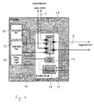
DPU 10 are depicted in more detail infigure 4 . Theselection switch 17 of theselection circuit 11 includes a first port for a connection with theAGW 20 via thecopper line 7 and a second port for a connection with thecopper line 6 for providing the xDSL and PSTN services, and a third port being connected inside theDPU 10 with a broadband analogfront end 14 for providing the G.fast service. Theselection circuit 11 comprises in addition a monitor and controllogic 15 being coupled with the first port of theselection switch 17 and being coupled via aswitch drive logic 16 with theselection switch 17 for controlling the selection of the xDSL and PSTN services and the G.fast service. TheDPU 10 includes further a DPUpower supply unit 13, which is coupled with the third port of theselection switch 17 for powering theDPU 10, when the G.fast service is selected and a supply voltage for theDPU 10 is provided by theAGW 20 via thecopper line 7. - When the xDSL and PSTN services are in operation and the monitor and control
logic 15 detects switching pulses of theAGW drive logic 21 on thecopper line 7, it switches theselection switch 17 via theswitch drive logic 16 to the broadband analogfront end 14 and to the DPUpower supply unit 13 for enabling the G.fast service. TheDPU 10 includes further aDPU drive logic 12 being coupled with theswitch drive logic 16, via which theselection switch 17 is kept in the G.fast selection mode, when a reverse supply power is provided by theAGW 20 and the DPU control pulses are switched off by theAGW 20. - When the reverse supply power for the
DPU 10 is switched off during operation of the G.fast service, theDPU 10 switches automatically to the xDSL and PSTN services. This can be provided for example by using aselection switch 17, which switches automatically to the xDSL and PSTN services in a powerless state. - Relevant parts of the
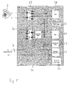
AGW 20 are depicted in more detail infigure 5 . For the operation of the xDSL and the G.fast services, a broadband analogfront end 23 is included, which processes the upstream and downstream data traffic as provided via thecopper line 7. For the operation of the PSTN service, aservice switch 26 is included being controlled by a serviceswitch drive logic 29, which connects thecopper line 7 with alow pass filter 25 in case the xDSL and PSTN services are enabled, and which disconnects thelow pass filter 25 in case the G.fast service is enabled. Thelow pass filter 25 provides a connection with thetelephone 3 via alife line relay 27. TheAGW 20 comprises further anFXS interface 28 and anFXO interface 24 for the PSTN service, the interface 24being connectable via thelow pass filter 25 and theservice switch 26 with thecopper line 7. - For the G.fast service, the
AGW 20 includes areverse power supply 22 for providing the reverse supply power to theDPU 10. Thereverse power supply 22 and theAGW drive logic 21 are both coupled with thecopper line 7. The reverse supply power is in particular a DC supply power. - The operation of the
DPU 10 and theAGW 20 is illustrated in a flow chart depicted infigure 6 . In the initial condition,step 60, theDPU 10 and theAGW 20 are off and in a default state, in which theselection switch 17 is switched to the xDSL and PSTN services. When theAGW 20 is switched on,step 62, theAGW 20 detects that the xDSL and the PSTN services are connected via thecopper lines reverse power supply 22 remains switched off. Theservice switch 26 is in a default state connecting thecopper line 7 with thelow pass filter 25. TheAGW 20 then checks whether an xDSL service is available, detectable by the broadband analogfront end 23, and/or a PSTN service is available, detectable by theFXO circuit 24. Is an xDSL service or a PSTN service detected, the respective service is enabled and provided by theAGW 20 to the customer,step 66, which is indicated on theAGW 20 by indicator lights, not shown. - In case no xDSL or PSTN service is detected by the
AGW 20, theCPE 20 starts a procedure to detect whether there is a DPU connected to theAGW 20. TheAGW 20 switches theservice switch 26 to disconnect thelow pass filter 25 from thecopper line 7. The AGW drivelogic 21 then generates signal pulses being applied to thecopper line 7 to power up a DPU,e.g. DPU 10. In case theDPU 10 is available, the signal pulses provide sufficient power to operate the monitor and controllogic 15 and to set theselection switch 17 to the G.fast service via theswitch drive logic 16. The signal pulses are applied for a time interval t1. - After t1, the signal pulses of the
AGW drive logic 21 are switched off, and the monitor and controllogic 15 is operating at least for a time interval t2, during which the monitor and controllogic 15 switches theselection switch 17 via theswitch drive logic 16 to connect the analogfront end 14 and the DPUpower supply unit 13 with thecopper line 7,step 70. - In a
further step 72, theAGW 20 switches on thereverse power supply 22 after a time t3 for providing power via thecopper line 7 to theDPU 10. Thereverse power supply 22 then checks whether there is a DPU available,step 74. If theDPU 10 is detected within a time t2 minus t4, thereverse power supply 22 remains switched on. - The
DPU power supply 13 then starts up to provide power for the operation of theDPU 10, and theDPU drive logic 12 triggers theswitch drive logic 16 to keep the connection of thecopper line 7 with theDPU power supply 13 and the analogfront end 14 via theselection circuit 11,step 76. TheDPU 10 is then enabled for the G.fast service. - In case the
AGW 20 does not detect theDPU 10, thereverse power supply 22 is switched off after t2, also at the end of t2 theselection circuit 15 no longer has power, causing theswitch 17 to revert to the xDSL and PSTN services. The procedure then continues withstep 62,line 78. If xDSL and PSTN services are detected, these services are then provided to the customer,step 66. - When the
AGW 20 is switched off at any time during the G.fast operation of theDPU 10, theDPU 10, respectively the G.fast channel of theDPU 10 associated with theAGW 20, switches off accordingly, because the reverse power from theAGW 20 is interrupted. The procedure returns then to step 60, vialine 80, in which thecopper line 7 is connected to thecopper line 6 for providing xDSL and PSTN services. The procedure returns also to step 60, in case theAGW 20 is switched off afterstep 66. - With the
DPU 10, therefore existing copper lines can be reused to offer both legacy services, xDSL and PTSN services, and a G.fast service to a customer. The legacy services and the new service can be provided with thesame AGW 20 and a transparent migration between the new service and the legacy services is possible. A POTS service for thetelephone 3 may be maintained, until the migration to the G.fast service is enabled. In case the G.fast service is enabled, a Voice-over-IP (VoIP) service can be provided without reconnecting the port of thetelephone 3, or changing the handset. An early installation of a DPU in the field is possible by only including the selection switch 17: a G.fast service card including the modules 12-16 can be added later to the DPU. The operation of the DPU with theAGW 20 can be provided always without affecting another customer being connected to the DPU. - Also other embodiments may be utilized by one skilled in the art without departing from the scope of the present disclosure. The disclosure resides therefore in the claims herein after appended.
Claims (16)
1. Method for operating a distribution point unit (DPU) comprising a selection switch (17) and a monitor and control logic (15) for providing a first and a second service, the selection switch having a default state, in which the first service is provided, comprising
receiving a switching signal powering the monitor and control logic (68), and
switching the selection switch from the first service to the second service by the monitor and control logic (70), after receiving the switching signal.
2. The method of claim 1, comprising
the selection switch switching from the second service to the first service in a powerless state of a selection circuit (11) comprising the selection switch (17), wherein the selection circuit (11) is adapted such that it only reacts to the pulse signals sent out by the AGW drive logic 21 and does not react to the xDSL and PSTN services.
the selection switch switching from the second service to the first service in a powerless state of a selection circuit (11) comprising the selection switch (17), wherein the selection circuit (11) is adapted such that it only reacts to the pulse signals sent out by the AGW drive logic 21 and does not react to the xDSL and PSTN services.
3. The method of claim 1 or 2, comprising
receiving a supply power in a DPU power supply unit (13) via the selection switch after the second service is selected by the selection switch (70), and the DPU power supply unit causing the selection switch to keep the second service, for example via a switch drive logic (16).
receiving a supply power in a DPU power supply unit (13) via the selection switch after the second service is selected by the selection switch (70), and the DPU power supply unit causing the selection switch to keep the second service, for example via a switch drive logic (16).
3. The method of claim 1 or 2, comprising
applying the switching signal for a time interval to power the monitor and control logic temporarily (68).
applying the switching signal for a time interval to power the monitor and control logic temporarily (68).
4. The method of claim 1, 2 or 3, comprising
receiving the supply power in the DPU power supply unit after the switching signal is switched off, the supply power powering the DPU and to provide the second service to a customer premises equipment (CPE) device.
receiving the supply power in the DPU power supply unit after the switching signal is switched off, the supply power powering the DPU and to provide the second service to a customer premises equipment (CPE) device.
5. The method of one of the preceding claims, wherein the switching signal is a DC-free switching signal not including a direct current voltage, for example at least one of a pulse signal and an alternating current.
6. The method of one of the preceding claims, wherein the first service is an xDSL (Digital Subscriber Line) and/or a PSTN (Public Switched Telephone Network) service, and the second service is a G.fast service.
7. Distribution point unit (DPU) comprising a selection switch (17) and a monitor and control logic (15) for providing a first and a second service, characterized that
the selection switch is arranged to provide the first service in a default mode, and
the monitor and control logic is adapted to receive a switching signal powering the monitor and control logic and causing the monitor and control logic to switch to the second service.
the selection switch is arranged to provide the first service in a default mode, and
the monitor and control logic is adapted to receive a switching signal powering the monitor and control logic and causing the monitor and control logic to switch to the second service.
8. The DPU of claim 7, comprising a DPU power supply unit (13) coupled with the selection switch to receive a supply power from a CPE (Customer Premises Equipment) after the second service is selected, the DPU power supply unit being used to power the DPU and to provide the second service to the CPE.
9. The DPU of claim 7 or 8, comprising a switch drive logic (16) coupled with the selection switch to cause the selection switch to maintain the second service.
10. The DPU of claim 7, 8 or 9, wherein the DPU is designed for an operation with a CPE device in accordance with a G.fast standard.
11. DPU of one of the preceding claims 7-10, being adapted for performing a method according to one of the preceding claims 1-6.
12. Customer premises equipment (CPE) device, comprising a reverse power supply (22) and an AGW drive logic (21) for powering a DPU, characterized that
the AGW drive logic (21) is adapted to provide a switching signal for powering a monitor and control logic (15) of a DPU and to cause the monitor and control logic to switch from a first service to a second service, and
the reverse power supply (22) is adapted to provide a supply power for the DPU, after the switching signal is switched off by the AGW drive logic (21).
the AGW drive logic (21) is adapted to provide a switching signal for powering a monitor and control logic (15) of a DPU and to cause the monitor and control logic to switch from a first service to a second service, and
the reverse power supply (22) is adapted to provide a supply power for the DPU, after the switching signal is switched off by the AGW drive logic (21).
13. The CPE device of claim 12, characterized in that the first service includes an xDSL and a PSTN service and the CPE device comprises
a service switch (26) coupled with a port being provided to connect with a copper line (7) and a service switch drive logic (29) for selecting the PSTN service, and
a broadband analog front end (23) coupled with the port for providing the xDSL service and the second service, wherein the service switch (26) disconnects the PSTN service and wherein the xDSL service is disabled, before the AGW drive logic (21) provides the switching signal.
a service switch (26) coupled with a port being provided to connect with a copper line (7) and a service switch drive logic (29) for selecting the PSTN service, and
a broadband analog front end (23) coupled with the port for providing the xDSL service and the second service, wherein the service switch (26) disconnects the PSTN service and wherein the xDSL service is disabled, before the AGW drive logic (21) provides the switching signal.
14. The CPE device of claim 12 or 13, wherein the CPE device is adapted to detect whether a DPU is connected to the CPE device, and wherein the CPE device enables the first service, if it is determined that a DPU is not detected.
15. The CPE device of claim 12, 13 or 14, being adapted to perform a method for operating a DPU according to one of the preceding claims 1-6.
Priority Applications (6)
| Application Number | Priority Date | Filing Date | Title |
|---|---|---|---|
| EP15305629.6A EP3086507A1 (en) | 2015-04-24 | 2015-04-24 | Method for operating a distribution point unit, respective distribution point unit and cpe device |
| CN201680023759.9A CN107534561A (en) | 2015-04-24 | 2016-03-18 | For operating method, corresponding distribution dot element and the cpe device of distribution dot element |
| US15/568,591 US10397018B2 (en) | 2015-04-24 | 2016-03-18 | Method for operating a distribution point unit, respective distribution point unit and CPE device |
| EP16711240.8A EP3286876A1 (en) | 2015-04-24 | 2016-03-18 | Method for operating a distribution point unit, respective distribution point unit and cpe device |
| BR112017022913A BR112017022913A2 (en) | 2015-04-24 | 2016-03-18 | method for operating a distribution point unit, respective distribution point unit and cpe device |
| PCT/EP2016/055973 WO2016169707A1 (en) | 2015-04-24 | 2016-03-18 | Method for operating a distribution point unit, respective distribution point unit and cpe device |
Applications Claiming Priority (1)
| Application Number | Priority Date | Filing Date | Title |
|---|---|---|---|
| EP15305629.6A EP3086507A1 (en) | 2015-04-24 | 2015-04-24 | Method for operating a distribution point unit, respective distribution point unit and cpe device |
Publications (1)
| Publication Number | Publication Date |
|---|---|
| EP3086507A1 true EP3086507A1 (en) | 2016-10-26 |
Family
ID=53189748
Family Applications (2)
| Application Number | Title | Priority Date | Filing Date |
|---|---|---|---|
| EP15305629.6A Withdrawn EP3086507A1 (en) | 2015-04-24 | 2015-04-24 | Method for operating a distribution point unit, respective distribution point unit and cpe device |
| EP16711240.8A Withdrawn EP3286876A1 (en) | 2015-04-24 | 2016-03-18 | Method for operating a distribution point unit, respective distribution point unit and cpe device |
Family Applications After (1)
| Application Number | Title | Priority Date | Filing Date |
|---|---|---|---|
| EP16711240.8A Withdrawn EP3286876A1 (en) | 2015-04-24 | 2016-03-18 | Method for operating a distribution point unit, respective distribution point unit and cpe device |
Country Status (5)
| Country | Link |
|---|---|
| US (1) | US10397018B2 (en) |
| EP (2) | EP3086507A1 (en) |
| CN (1) | CN107534561A (en) |
| BR (1) | BR112017022913A2 (en) |
| WO (1) | WO2016169707A1 (en) |
Cited By (3)
| Publication number | Priority date | Publication date | Assignee | Title |
|---|---|---|---|---|
| CN108023796A (en) * | 2018-01-12 | 2018-05-11 | 普联技术有限公司 | Customer terminal equipment, switch method of remote signal method, control device and storage medium |
| DE102017104242A1 (en) | 2017-03-01 | 2018-09-06 | Adtran GmbH | Migration between access services |
| WO2019157795A1 (en) * | 2018-02-13 | 2019-08-22 | 华为技术有限公司 | Communication method, equipment and system |
Families Citing this family (2)
| Publication number | Priority date | Publication date | Assignee | Title |
|---|---|---|---|---|
| CN109039659B (en) * | 2018-06-13 | 2021-06-04 | 普联技术有限公司 | Fast reverse power supply system and local side equipment |
| EP3859984B1 (en) * | 2020-01-30 | 2023-05-17 | Nokia Solutions and Networks Oy | Melt with reverse power feed |
Citations (3)
| Publication number | Priority date | Publication date | Assignee | Title |
|---|---|---|---|---|
| US8601289B1 (en) | 2011-02-21 | 2013-12-03 | Adtran, Inc. | Optical network unit with redundant reverse powering from customer premises equipment |
| EP2816758A1 (en) * | 2013-06-17 | 2014-12-24 | Alcatel Lucent | Method for dealing with anomalous conditions in a reverse power network, and power injector for use in such a method |
| EP2830302A1 (en) * | 2013-07-23 | 2015-01-28 | British Telecommunications public limited company | Reverse powering system for telecommunications node |
Family Cites Families (9)
| Publication number | Priority date | Publication date | Assignee | Title |
|---|---|---|---|---|
| US10142023B2 (en) | 2003-01-31 | 2018-11-27 | Centurylink Intellectual Property Llc | Antenna system and methods for wireless optical network termination |
| US8543008B2 (en) | 2005-03-01 | 2013-09-24 | Alexander I Soto | System and method for a subscriber powered network element |
| US9077818B2 (en) * | 2005-04-13 | 2015-07-07 | Alcatel Lucent | Remotely migrating from a first service to a second service |
| US7652504B2 (en) | 2006-12-13 | 2010-01-26 | Apple Inc. | Low latency, power-down safe level shifter |
| EP1988664A1 (en) | 2007-04-30 | 2008-11-05 | British Telecommunications Public Limited Company | Communications network |
| WO2009102243A1 (en) * | 2008-02-11 | 2009-08-20 | Telefonaktiebolaget Lm Ericsson (Publ) | Remote powering for fttx via existing wire |
| TWI474666B (en) * | 2012-05-23 | 2015-02-21 | Accton Technology Corp | A method for power source management and an apparatus for power source management |
| WO2014194532A1 (en) * | 2013-06-08 | 2014-12-11 | 华为技术有限公司 | Network node transmission method, and device and system thereof |
| EP2866399A1 (en) * | 2013-10-22 | 2015-04-29 | Alcatel Lucent | Transmit circuitry and method for transmitting a signal |
-
2015
- 2015-04-24 EP EP15305629.6A patent/EP3086507A1/en not_active Withdrawn
-
2016
- 2016-03-18 WO PCT/EP2016/055973 patent/WO2016169707A1/en not_active Ceased
- 2016-03-18 CN CN201680023759.9A patent/CN107534561A/en active Pending
- 2016-03-18 BR BR112017022913A patent/BR112017022913A2/en not_active IP Right Cessation
- 2016-03-18 EP EP16711240.8A patent/EP3286876A1/en not_active Withdrawn
- 2016-03-18 US US15/568,591 patent/US10397018B2/en not_active Expired - Fee Related
Patent Citations (3)
| Publication number | Priority date | Publication date | Assignee | Title |
|---|---|---|---|---|
| US8601289B1 (en) | 2011-02-21 | 2013-12-03 | Adtran, Inc. | Optical network unit with redundant reverse powering from customer premises equipment |
| EP2816758A1 (en) * | 2013-06-17 | 2014-12-24 | Alcatel Lucent | Method for dealing with anomalous conditions in a reverse power network, and power injector for use in such a method |
| EP2830302A1 (en) * | 2013-07-23 | 2015-01-28 | British Telecommunications public limited company | Reverse powering system for telecommunications node |
Non-Patent Citations (2)
| Title |
|---|
| "Access, Terminals, Transmission and Multiplexing (ATTM); European Requirements for Reverse Powering of Remote Access Equipment;ETSI TS 101 548", ETSI DRAFT; ETSI TS 101 548, EUROPEAN TELECOMMUNICATIONS STANDARDS INSTITUTE (ETSI), 650, ROUTE DES LUCIOLES ; F-06921 SOPHIA-ANTIPOLIS ; FRANCE, vol. ATTM - TM6, no. V1.2.1, 23 April 2015 (2015-04-23), pages 1 - 35, XP014236145 * |
| "ETSI TR 102 629 V2.1.2 (2011-03) - Access, Terminals, Transmission and Multiplexing (ATTM); Reverse Power Feed for Remote Nodes", 1 March 2011 (2011-03-01), Sophia Antipolis Cedex - FRANCE, pages 2011 - 3, XP055166621, Retrieved from the Internet <URL:http://www.etsi.org/deliver/etsi_tr/102600_102699/102629/02.01.02_60/tr_102629v020102p.pdf> [retrieved on 20150202] * |
Cited By (4)
| Publication number | Priority date | Publication date | Assignee | Title |
|---|---|---|---|---|
| DE102017104242A1 (en) | 2017-03-01 | 2018-09-06 | Adtran GmbH | Migration between access services |
| CN108023796A (en) * | 2018-01-12 | 2018-05-11 | 普联技术有限公司 | Customer terminal equipment, switch method of remote signal method, control device and storage medium |
| CN108023796B (en) * | 2018-01-12 | 2023-05-16 | 上海联虹技术有限公司 | Client terminal device, signal switching control method, control device, and storage medium |
| WO2019157795A1 (en) * | 2018-02-13 | 2019-08-22 | 华为技术有限公司 | Communication method, equipment and system |
Also Published As
| Publication number | Publication date |
|---|---|
| WO2016169707A1 (en) | 2016-10-27 |
| US10397018B2 (en) | 2019-08-27 |
| EP3286876A1 (en) | 2018-02-28 |
| US20180115436A1 (en) | 2018-04-26 |
| BR112017022913A2 (en) | 2018-07-24 |
| CN107534561A (en) | 2018-01-02 |
Similar Documents
| Publication | Publication Date | Title |
|---|---|---|
| US10397018B2 (en) | Method for operating a distribution point unit, respective distribution point unit and CPE device | |
| AU2016266678B2 (en) | Provisioning of new broadband communication services using reverse power feeding | |
| US8666057B2 (en) | Remote powering of DSL ADMs | |
| EP2816758A1 (en) | Method for dealing with anomalous conditions in a reverse power network, and power injector for use in such a method | |
| EP3091723B1 (en) | Service isolation processing method, device, system, dpu and network adapter | |
| EP3117596B1 (en) | Systems and methods for providing back power to a service unit | |
| EP2829015B1 (en) | Power distribution for telecommunications system | |
| US20100150564A1 (en) | Communications network | |
| CN104365080A (en) | Method for terminating operation of client equipment device and corresponding client equipment device using same | |
| EP1713247B1 (en) | Remotely migrating from a first service to a second service | |
| US9473241B1 (en) | Systems and methods for controlling the connectivity of a drop connection | |
| CN101690151B (en) | Arrangement and method relating to subscriber line connections | |
| US10298773B2 (en) | Systems and methods for connecting and disconnecting to a ring network or linear netowrk | |
| US8488594B2 (en) | Apparatus and system for bridging communication signals | |
| EP2642688A1 (en) | Power distribution for telecommunications system | |
| EP3316564B1 (en) | Power-efficient decoding arrangement for rpf operation | |
| EP2230826A1 (en) | Operation of telecommunications connections by means of a sealing current | |
| JP2006333362A (en) | Communication device |
Legal Events
| Date | Code | Title | Description |
|---|---|---|---|
| PUAI | Public reference made under article 153(3) epc to a published international application that has entered the european phase |
Free format text: ORIGINAL CODE: 0009012 |
|
| AK | Designated contracting states |
Kind code of ref document: A1 Designated state(s): AL AT BE BG CH CY CZ DE DK EE ES FI FR GB GR HR HU IE IS IT LI LT LU LV MC MK MT NL NO PL PT RO RS SE SI SK SM TR |
|
| AX | Request for extension of the european patent |
Extension state: BA ME |
|
| STAA | Information on the status of an ep patent application or granted ep patent |
Free format text: STATUS: THE APPLICATION IS DEEMED TO BE WITHDRAWN |
|
| 18D | Application deemed to be withdrawn |
Effective date: 20170427 |