EP3086467A1 - Method of controlling an electrical machine - Google Patents
Method of controlling an electrical machine Download PDFInfo
- Publication number
- EP3086467A1 EP3086467A1 EP15164661.9A EP15164661A EP3086467A1 EP 3086467 A1 EP3086467 A1 EP 3086467A1 EP 15164661 A EP15164661 A EP 15164661A EP 3086467 A1 EP3086467 A1 EP 3086467A1
- Authority
- EP
- European Patent Office
- Prior art keywords
- airgap
- current
- negative
- width
- airgap width
- Prior art date
- Legal status (The legal status is an assumption and is not a legal conclusion. Google has not performed a legal analysis and makes no representation as to the accuracy of the status listed.)
- Granted
Links
Images


Classifications
-
- H—ELECTRICITY
- H02—GENERATION; CONVERSION OR DISTRIBUTION OF ELECTRIC POWER
- H02P—CONTROL OR REGULATION OF ELECTRIC MOTORS, ELECTRIC GENERATORS OR DYNAMO-ELECTRIC CONVERTERS; CONTROLLING TRANSFORMERS, REACTORS OR CHOKE COILS
- H02P21/00—Arrangements or methods for the control of electric machines by vector control, e.g. by control of field orientation
- H02P21/12—Stator flux based control involving the use of rotor position or rotor speed sensors
-
- H—ELECTRICITY
- H02—GENERATION; CONVERSION OR DISTRIBUTION OF ELECTRIC POWER
- H02K—DYNAMO-ELECTRIC MACHINES
- H02K11/00—Structural association of dynamo-electric machines with electric components or with devices for shielding, monitoring or protection
- H02K11/20—Structural association of dynamo-electric machines with electric components or with devices for shielding, monitoring or protection for measuring, monitoring, testing, protecting or switching
- H02K11/21—Devices for sensing speed or position, or actuated thereby
-
- H—ELECTRICITY
- H02—GENERATION; CONVERSION OR DISTRIBUTION OF ELECTRIC POWER
- H02K—DYNAMO-ELECTRIC MACHINES
- H02K7/00—Arrangements for handling mechanical energy structurally associated with dynamo-electric machines, e.g. structural association with mechanical driving motors or auxiliary dynamo-electric machines
- H02K7/08—Structural association with bearings
- H02K7/09—Structural association with bearings with magnetic bearings
-
- H—ELECTRICITY
- H02—GENERATION; CONVERSION OR DISTRIBUTION OF ELECTRIC POWER
- H02P—CONTROL OR REGULATION OF ELECTRIC MOTORS, ELECTRIC GENERATORS OR DYNAMO-ELECTRIC CONVERTERS; CONTROLLING TRANSFORMERS, REACTORS OR CHOKE COILS
- H02P21/00—Arrangements or methods for the control of electric machines by vector control, e.g. by control of field orientation
-
- H—ELECTRICITY
- H02—GENERATION; CONVERSION OR DISTRIBUTION OF ELECTRIC POWER
- H02P—CONTROL OR REGULATION OF ELECTRIC MOTORS, ELECTRIC GENERATORS OR DYNAMO-ELECTRIC CONVERTERS; CONTROLLING TRANSFORMERS, REACTORS OR CHOKE COILS
- H02P21/00—Arrangements or methods for the control of electric machines by vector control, e.g. by control of field orientation
- H02P21/22—Current control, e.g. using a current control loop
-
- H—ELECTRICITY
- H02—GENERATION; CONVERSION OR DISTRIBUTION OF ELECTRIC POWER
- H02P—CONTROL OR REGULATION OF ELECTRIC MOTORS, ELECTRIC GENERATORS OR DYNAMO-ELECTRIC CONVERTERS; CONTROLLING TRANSFORMERS, REACTORS OR CHOKE COILS
- H02P21/00—Arrangements or methods for the control of electric machines by vector control, e.g. by control of field orientation
- H02P21/24—Vector control not involving the use of rotor position or rotor speed sensors
- H02P21/28—Stator flux based control
-
- H—ELECTRICITY
- H02—GENERATION; CONVERSION OR DISTRIBUTION OF ELECTRIC POWER
- H02K—DYNAMO-ELECTRIC MACHINES
- H02K2201/00—Specific aspects not provided for in the other groups of this subclass relating to the magnetic circuits
- H02K2201/03—Machines characterised by aspects of the air-gap between rotor and stator
-
- H—ELECTRICITY
- H02—GENERATION; CONVERSION OR DISTRIBUTION OF ELECTRIC POWER
- H02P—CONTROL OR REGULATION OF ELECTRIC MOTORS, ELECTRIC GENERATORS OR DYNAMO-ELECTRIC CONVERTERS; CONTROLLING TRANSFORMERS, REACTORS OR CHOKE COILS
- H02P21/00—Arrangements or methods for the control of electric machines by vector control, e.g. by control of field orientation
- H02P21/14—Estimation or adaptation of machine parameters, e.g. flux, current or voltage
- H02P21/141—Flux estimation
-
- Y—GENERAL TAGGING OF NEW TECHNOLOGICAL DEVELOPMENTS; GENERAL TAGGING OF CROSS-SECTIONAL TECHNOLOGIES SPANNING OVER SEVERAL SECTIONS OF THE IPC; TECHNICAL SUBJECTS COVERED BY FORMER USPC CROSS-REFERENCE ART COLLECTIONS [XRACs] AND DIGESTS
- Y02—TECHNOLOGIES OR APPLICATIONS FOR MITIGATION OR ADAPTATION AGAINST CLIMATE CHANGE
- Y02E—REDUCTION OF GREENHOUSE GAS [GHG] EMISSIONS, RELATED TO ENERGY GENERATION, TRANSMISSION OR DISTRIBUTION
- Y02E10/00—Energy generation through renewable energy sources
- Y02E10/70—Wind energy
- Y02E10/72—Wind turbines with rotation axis in wind direction
Definitions
- the invention describes a method of controlling an electrical machine; a control arrangement of an electrical machine; and a wind turbine.
- the width of the airgap between armature and field is related to the electromagnetic performance of the electrical machine.
- the width of the airgap is generally understood to be the shortest distance between magnets of the field and windings of the armature.
- a narrow airgap improves the electromagnetic performance of the machine. Therefore, the airgap should be as small as possible in order to maximise the electromagnetic performance.
- the minimum airgap height is limited by various factors. For example, allowance must be made for manufacturing tolerances on components such as rotor housing, magnets, stator body, etc. Also, temperature differences must be taken into account, since the armature generally reaches a higher temperature than the rotor on account of losses in the windings of the armature. Thermal expansion can decrease the height of the airgap, particularly when the stator and its windings are arranged within an outer rotor.
- Eccentricity of a circularly cylindrical component - e.g. the rotor - can result in local variations in the airgap height. Eccentricity of a permanent nature may develop for example during manufacture of the machine, during transport and installation of the machine or during its lifetime. Temporary eccentricity can also arise during adverse weather conditions from uneven wind loading of the rotor blades and a resulting imbalance in the magnetic forces. Eccentricity is associated with a non-uniform airgap width over the airgap circumference, i.e. the airgap will have regions with nominal width but also regions that are narrower than the nominal width and regions that are wider than the nominal width.
- any measureable and/or predictable detrimental factors such as eccentricity, manufacturing tolerances, temperatures etc., are obtained to predict a situation in which it would be safer to down-regulate the electrical machine or to shut it down in order to reduce the risk of collision.
- the electrical machine can be designed to take the above factors into consideration, i.e. with an airgap that is wide enough to avoid collision between rotor and stator during the lifetime of the machine, even in a worst-case condition given by the accumulation of detrimental eccentricity factors mentioned above.
- a suitably wide airgap can ensure that a local narrowing due to eccentricity is still within a safe limit, so that the electrical machine can continue to operate even during such a worst-case situation.
- a relatively large airgap width comes with the penalty of worse electromagnetic performance overall.
- a relatively large airgap presents a trade-off between a possible extension of the generator's uptime and a definite sacrifice of power output.
- the method of controlling an electrical machine - with a rotor and a stator separated by an airgap - comprises the steps of obtaining a measurement of airgap width during operation of the machine; determining a corrective value of negative Id current on the basis of the airgap width measurement; and injecting the negative Id current to correct the airgap width.
- injecting negative Id current is used in its accepted context: a negative value of Id current is determined under application of the known direct-quadrature-zero (dq0) transformation, and an inverse transform is applied to obtain values of phase current to be injected into the windings.
- dq0 direct-quadrature-zero
- FIG. 8 shows a greatly simplified cross-section through a prior art outer rotor generator 2, in a plane orthogonal to the axis of rotation R of the generator 2.
- the diagram shows a stator 21 arranged on a hollow shaft 23.
- the stator 21 carries the generator windings (not shown) between projecting stator teeth.
- the outer rotor 20 carries an arrangement of permanent magnets 200.
- the magnets and windings are separated by an airgap AG.
- the airgap AG should be as uniform as possible, and is preferably very narrow, for example only a few millimetres, in order to make the generator 2 as efficient as possible.
- the outer rotor 20 is supported at the drive end DE by a main bearing 24 about a central hollow shaft 23. Any eccentricity in the rotor 20 results in a departure from its ideal circular cross-sectional shape and airgap regions that are too narrow and other airgap regions that are too wide. This is made worse by the stronger radial magnetic force acting across the narrow airgap regions, making them even narrower. A collision between rotor 20 and stator 21 could result, as indicated by the warning symbol in the diagram.
- An advantage of the method according to the invention is that the electrical machine can be controlled during operation in such a way that its airgap is prevented at all times from becoming critically narrow.
- the method according to the invention can therefore avoid having to down-regulate or shut-down the electrical machine in order to avoid the risk of collision damage explained above.
- the method according to the invention can be applied to various different kinds of synchronous or asynchronous electrical machine, for example it may be used to control a permanent-magnet electrical machine, an electrically excited machine without permanent magnets, etc.
- the control arrangement of an electrical machine - with a rotor and a stator separated by an airgap - comprises a measuring arrangement realized to obtain a measurement of airgap width during operation of the machine; an evaluation unit realized to determine a corrective value of negative Id current on the basis of the airgap width measurement; and a current injection module for injecting the negative Id current into windings of the generator to correct the airgap width.
- An advantage of the control arrangement according to the invention is that it can easily determine whether measures should be taken to avoid a deterioration of the airgap quality.
- the control arrangement according to the invention can ensure that the width of the airgap - at all points over its circumference - never decreases to a critical level, for example one that would necessitate shutting down of the electrical machine.
- the control arrangement can also be installed relatively easily to upgrade an existing electrical machine.
- the current injection module can be realised using an already existing current controller.
- Present-day electrical machines such as wind turbine generators are controlled using a combination of hardware and software modules.
- the current injection module of the control arrangement according to the invention might simply comprise an adaptation or upgrade of an already existing software control algorithm.
- a wind turbine controller may already have a module that adjusts the Id current in order to regulate the terminal voltage of generator.
- Such a module can be adapted relatively easily to take into account any corrective Id current determined by the evaluation unit.
- the wind turbine comprises a generator and such a control arrangement for carrying out the steps of the control method according to the invention.
- An advantage of the wind turbine according to the invention is that it can continue to operate even under adverse conditions in which several detrimental factors accrue.
- the control arrangement and method according to the invention allow the generator to continue to operate at a high power output level (with resulting high rotor/stator temperatures), since any unfavourable reduction in airgap width can be pre-empted or avoided by the timely injection of negative Id current into the windings of the stator, as will be explained in more detail below.
- the electrical machine is a three-phase AC machine such as a three-phase generator.
- the stator is the armature and carries the windings
- the rotor is the field and carries the magnets.
- the step of determining a corrective value of negative Id current is performed when the airgap width measurement approaches a predetermined minimum.
- This predetermined minimum may correspond to a critical airgap width that would otherwise require down-regulation or shutdown (for a machine without this control arrangement).
- the predetermined minimum may be slightly higher than this critical airgap width.
- the corrective measures are applied in a pre-emptive manner to prevent the airgap from ever becoming critically narrow at any point over the circumference of the airgap.
- a dq0 transformation is a mathematical transformation of three-phase time-domain signals from a stationary coordinate system to a rotating coordinate system.
- the dq0 transform can greatly simplify analysis, since three AC quantities are reduced to two DC quantities. After carrying out a relatively straightforward computation on the DC quantities, the inverse transform is applied to recover the corresponding three-phase AC values.
- the dq0 transformation effectively converts three-phase stator and rotor quantities into a single rotating reference frame, thereby eliminating the effect of time varying inductances which would otherwise make such computations extremely complex.
- a three-phase synchronous machine can be modelled by three windings that are separated by 120 physical degrees, and by three phase currents that are equal in magnitude and are separated from one another by 120 electrical degrees. The current lags the voltage by a fixed amount.
- the dq0 transformation is applied to such a machine, the d-q axes (which are at an angle of 90° to each other) rotate with an angular velocity that is equal to the angular velocity as the phase voltages and currents.
- the two DC currents in this dq0 reference frame are referred to as "Id current” (lying on the d axis) and “Iq current” (lying on the q axis).
- the direction of magnetic flux in the airgap is along the d axis. Therefore, injection of negative Id current into the windings of the electrical machine will reduce the stator magnetic flux.
- This key idea of the invention has the effect that the "pull" between rotor and stator is reduced, with the result that a further decrease in airgap width is prevented, particularly in an already overly narrow airgap region.
- a corrective value of negative Id current is injected to maintain the airgap width at the predetermined minimum.
- the airgap width measurement obtained by the measuring arrangement during operation of the machine may indicate that the smallest airgap width has reduced to a predetermined threshold level or minimum allowable airgap width.
- the evaluation unit can report this finding to the current control module, which responds by determining a corrective negative Id current value that will prevent the airgap from narrowing further. In this way, a minimum correction is carried out, so that the associated losses are also kept at a minimum.
- the relatively low cost of the correction is outweighed by the advantages of avoiding damage to the electrical machine and not having to down-regulate the machine or not having to shut it down.
- the corrective value of negative Id current can be injected for a limited duration. For example, assumptions can be made (based on prior observations) regarding a suitable duration. Alternatively, the corrective value of negative Id current can be injected until a "healthy" airgap width is reported by the measuring arrangement and evaluation unit.
- the measuring arrangement can comprise any means suitable for determining the width of the airgap at one or more points about the circumference of the airgap.
- the measuring arrangement comprises one or more distance sensors, for example a capacitive distance sensor, an optical sensor, an acoustic sensor, a laser distance sensor, etc.
- a laser distance sensor determines distance by directing a beam of laser light outward and measuring the time for the beam to be reflected back to the sensor. A very rapid and accurate measurement is made possible when such a sensor is used. This kind of sensor can continually measure the airgap width as the rotor rotates.
- Measurement values can be forwarded to the evaluation unit, which can identify any narrow regions in the airgap and can determine whether these are critically narrow, or whether they are still within a safe limit.
- a generator for which the outer rotor is supported by a single bearing at the drive end is particularly susceptible to airgap problems arising from eccentricity at the non-drive end.
- any critical narrowing of the airgap at the non-drive end can be identified and remedied in good time.
- the measuring arrangement comprises a number of temperature sensors, for example one or more temperature sensors arranged to monitor the temperature in the armature and/or one or more temperature sensors arranged to monitor the temperature in the field. Data obtained from observations made on existing machines and/or from simulations can be used to identify a threshold temperature range associated with eccentricity of the rotating component and a resulting critically narrow airgap region.
- such a threshold temperature can be identified in good time, and a suitable value of corrective negative Id current can be injected into the windings to avoid a further narrowing of the airgap.
- a corrective value of negative Id current is injected until a satisfactory airgap width is achieved over the entire circumference of the airgap. For example, if a critically narrow airgap region is reported, the necessary corrective Id current value is determined and applied until the situation is remedied.
- the corrective value of negative Id current is adapted according to a change in airgap width measurement. For example, the measurement arrangement might observe an increase in width at the critical region, indicating that the corrective measure is taking effect. To minimise losses, the corrective value of negative Id current can be gradually lessened as the airgap width returns towards a satisfactory value. Equally, if the width at the critical region continues to worsen initially, the corrective value of negative Id current can be gradually increased until the desired corrective effect is observed.
- the method according to the invention preferably comprises a prior step of establishing a relationship between values of airgap width and values of negative Id current.
- a preferred embodiment of the invention is based on observations that relate the magnitude of the radial force acting on a magnet to the airgap width. For example, information can be gathered for a specific machine, relating changes in radial force magnitude to changes in local airgap width. Further observations relate the Id current to the magnitude of radial force acting on a magnet.
- a look-up table is compiled, relating airgap width values to corrective Id current values.
- the number of value pairs can depend on the dimensions of the electrical machine and/or on the accuracy of the measurement arrangement.
- a laser distance sensor can deliver airgap width measurements that are accurate to within a few micrometres.
- fine adjustments can be made to the corrective negative Id current in order to achieve the desired reduction in radial force magnitude.
- the control arrangement according to the invention comprises a memory module for storing such a LUT relating values of airgap width to corrective Id current values.
- an electrical machine that will be controlled using the method according to the invention can be designed to have a narrower nominal airgap width. The reason for this is because it is no longer necessary to allow for the cumulative worst-case eccentricity problems in such a machine. It follows that an electrical machine that utilizes the inventive method and control arrangement will also have a corresponding higher output during normal operation, since the narrower airgap results in increased efficiency.
- the nominal airgap of such an electrical machine can be significantly narrower - for example up to 10% narrower - than the nominal airgap of a comparable prior art electrical machine that does not utilize the inventive method and control arrangement.
- a conventional direct-drive wind turbine with an outer rotor supported by a single bearing is particularly susceptible to airgap problems, since the heavy rotor is only supported at one end (usually the drive end). Any eccentricity already present in the rotor housing and/or any eccentricity arising during the lifetime of the generator or from wind loading will be magnified at the non-drive end.
- the nominal airgap of such a prior art generator must be large enough to prevent collision damage and/or the generator must be down-regulated or shut down during critical situations.
- a wind turbine according to the invention can be realized with a smaller nominal airgap width, for example up to 10% less, and the pre-emptive corrective action can prevent the airgap width from ever decreasing beyond a critical level.
- Fig. 1 shows a cross-section through a three-phase electrical machine 2 according to a first embodiment of the invention.
- the diagram is very simplified, and shows four magnet poles 200 arranged on an outer rotor 2, to face windings 210 arranged on a stator 21. Magnets 200 and windings 210 face each other across an airgap AG, which is also greatly exaggerated in the diagram.
- a monitoring arrangement 10 uses a distance sensor, for example a laser distance sensor, to measure the airgap width as the rotor 20 rotates about the stator 21. Airgap width measurements w AG are forwarded to an evaluation unit 11. This can decide whether an airgap width measurement w AG is narrower than an acceptable value.
- the evaluation unit 11 can consult a LUT stored in a memory module 111.
- the LUT can have been put together in a prior step as described above.
- the LUT is a list of value pairs relating airgap width values to corrective Id current values.
- w AG When a too-narrow airgap width measurement w AG is identified by the evaluation unit 11, it retrieves a corresponding corrective negative Id value 110 and forwards this to a current control module 12.
- the current control module 12 which can be part of an existing regulation arrangement of the electrical machine 2, responds by generating phase current values I A , I B , I C for injecting into the windings 210 of the machine 2.
- Fig. 2 shows a cross-section (also greatly simplified) through an electrical machine 2 according to a second embodiment of the invention.
- the monitoring arrangement 10 comprises temperature sensors for monitoring the temperature in the stator 21 and rotor 20. Temperature measurements T are forwarded (e.g. over a wireless interface) to an evaluation unit 11, which can decide - on the basis of a previously established relationship between temperature and airgap width - whether corrective measures should be taken to maintain a healthy airgap width. To this end, the evaluation unit 11 can consult a table stored in a memory module 111, in this case a list of value pairs relating temperature measurements to corrective Id current values.
- the step of obtaining a temperature measurement during operation of the machine can be regarded as a step of obtaining an airgap width measurement.
- the evaluation unit 11 retrieves a corresponding corrective negative Id value 110 and forwards this to a current control module 12, which can respond in the manner described above.
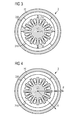
- Fig. 3 illustrates the action of radial magnetic force F R in an electrical machine 2.
- permanent magnets 200 When permanent magnets 200 are used, there is a radial magnetic force F R present even when there are no currents in the stator windings 210.
- a "pull" is exerted between the rotor 20 and stator 21 due to this radial magnetic force F R , and the magnitude of this force F R increases as the airgap width decreases. For this reason, any prior eccentricity combined with the increased radial magnetic force F R can have a serious detrimental effect on the airgap width, especially when the rotating component is supported at only one end by a single bearing.
- the nominal airgap width must to be sufficiently large to allow for local decreases in airgap width during operation of the machine.
- the magnitude of the radial magnetic force F R is reduced by injecting negative Id current into the windings 210.
- d and q axes of a dq0 reference frame are indicated in the diagram.
- the three-phase AC currents are transformed into two DC currents, namely Id current (which lies along the d axis) and Iq current (which lies along the q axis).
- the dq-axes rotate synchronously with rotor 20, whereby the d-axis is aligned with the centre of a reference magnet pole, and the q-axis extends between two adjacent poles.
- the radial magnetic field F R is in the direction of the d-axis.
- the windings 210 on the stator 21 are injected with currents in a controlled manner to produce a desired armature reaction field, whereby the armature reaction is the effect of the armature flux (arising when currents are induced in the windings) on the main field flux (the magnetic flux of the magnets).
- the armature reaction is the effect of the armature flux (arising when currents are induced in the windings) on the main field flux (the magnetic flux of the magnets).
- q-axis current Iq is injected into the windings 210, the resulting armature reaction field is in the direction of q-axis.
- This q-axis armature reaction field interacts with the magnetic field arising from the magnets to produce torque.
- a certain d-axis current Id when injected into the windings (after an appropriate inverse transform), will affect the magnetic field in the direction of d-axis.
- this d-axis armature reaction field does not produce torque and does not contribute to energy conversion.
- the Id current is zero or has a positive value
- the resulting d-axis armature reaction field is in the same direction as the magnetic field arising from the magnets, i.e. the forces are added, and the resulting radial magnetic force F R acts across the airgap to pull the magnets towards the windings.
- a negative Id current has the effect of reducing the radial magnetic force F R , and therefore corrects the undesirably narrow local airgap width.
- the entire airgap of the electrical machine is affected by the injection of negative Id current into the windings, i.e. the reduction in F R is felt over any narrow airgap regions over the entire circumference of the airgap.
- the same negative Id current results in a larger additive force at a local narrow airgap region, so that the effect of the method according to the invention is to reduce the eccentricity.
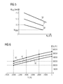
- Fig. 5 shows graphs 50, 51, 52 of airgap width w AG [mm] against radial magnetic force F R [kN] for comparable electrical machines, or for a single type of electrical machine with different nominal airgap widths.
- Graph 50 corresponds to a machine with a nominal airgap width of 3 mm
- graph 51 corresponds to a machine with a nominal airgap width of 5 mm
- graph 52 corresponds to a machine with a nominal airgap width of 7 mm.
- a locally narrow airgap region can result from eccentricity, and this can be worsened by the resulting increased larger radial magnetic force F R that acts to pull the magnets towards the stator.
- the diagram shows how the increasing radial magnetic force F R results in a decrease in local airgap width towards a critical minimum w MIN (using graph 50 as an example).
- a local airgap width that is less than this critical minimum w MIN can lead to a catastrophic collision between rotor and stator, and must be avoided.
- FIG. 6 shows graphs 60, 61, 62 of radial magnetic force F R [N] against Id current [A] for the same setup used to arrive at the data of Fig. 5 .
- a first graph 60 shows the relationship between negative Id current and radial force F R for a machine with a nominal airgap of 7 mm. The diagram shows that for an Id current of 0 A, the radial force acting on a pole is about 42 kN. As the Id current is decreased to minus 6,000 A (i.e. "the negative Id current is increased"), the radial force decreases to 20 kN.
- a second graph 61 shows the effect of negative Id current in a generator with a nominal airgap width of 5 mm.
- the radial force acting on a pole decreases from about 48 kN to 25 kN when the Id current is decreased from 0 to -6,000 A.
- a third graph 62 shows the effect of negative Id current in a generator with a nominal airgap width of 3 mm. In this case, the radial force acting on a pole decreases from about 54 kN to 30 kN when the Id current is decreased from 0 to -6,000 A. In each case, the radial force acting on a pole is reduced by more than 20 kN.
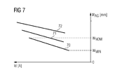
- Fig. 7 shows graphs 70, 71, 72 of airgap width w AG [mm] against Id current [A] obtained using the relationships established in Figs. 5 and 6 .
- Increasing quantities of negative Id current i.e. the Id current becomes more negative
- injected into the windings result in an improvement in airgap width, whereby the correction applies to a local narrow airgap region and acts to remedy this.
- the local airgap width can be increased from a critical minimum w MIN back towards the desirable nominal airgap width w NOM , indicated for one graph 70.
- the negative Id current can be injected into the windings for as long as necessary, i.e.
- Negative Id current injection is not always needed, and may be required only occasionally, for example when one or more worst case situations occur at the same time, e.g. worst component dimensions and/or worst stator temperature and/or worst rotor temperature, and/or worst inherent eccentricity. During normal operation, the negative Id current injection is not needed, so that any losses relating to the injection of Id current are kept to a minimum.
Landscapes
- Engineering & Computer Science (AREA)
- Power Engineering (AREA)
- Microelectronics & Electronic Packaging (AREA)
- Manufacture Of Motors, Generators (AREA)
- Permanent Magnet Type Synchronous Machine (AREA)
Abstract
Description
- The invention describes a method of controlling an electrical machine; a control arrangement of an electrical machine; and a wind turbine.
- In an electrical machine such as a motor or generator, the width of the airgap between armature and field is related to the electromagnetic performance of the electrical machine. The width of the airgap is generally understood to be the shortest distance between magnets of the field and windings of the armature. Generally, a narrow airgap improves the electromagnetic performance of the machine. Therefore, the airgap should be as small as possible in order to maximise the electromagnetic performance. However, in a very large electrical machine, it is very challenging to maintain a narrow airgap over its entire circumference and over its entire length, for example from the drive-end to the non-drive-end of a wind turbine generator. Care must be taken to ensure that the airgap is not smaller than a certain minimum at any point in order to avoid a collision between rotor and stator. The minimum airgap height is limited by various factors. For example, allowance must be made for manufacturing tolerances on components such as rotor housing, magnets, stator body, etc. Also, temperature differences must be taken into account, since the armature generally reaches a higher temperature than the rotor on account of losses in the windings of the armature. Thermal expansion can decrease the height of the airgap, particularly when the stator and its windings are arranged within an outer rotor.
- Eccentricity of a circularly cylindrical component - e.g. the rotor - can result in local variations in the airgap height. Eccentricity of a permanent nature may develop for example during manufacture of the machine, during transport and installation of the machine or during its lifetime. Temporary eccentricity can also arise during adverse weather conditions from uneven wind loading of the rotor blades and a resulting imbalance in the magnetic forces. Eccentricity is associated with a non-uniform airgap width over the airgap circumference, i.e. the airgap will have regions with nominal width but also regions that are narrower than the nominal width and regions that are wider than the nominal width. The problem is exacerbated by the fact that the magnetic force over a narrower airgap region is greater than the magnetic force over a wider airgap region, so that an electrical machine with an eccentric component is characterized by a magnetic force imbalance and a corresponding reduction in efficiency. These problems are especially detrimental in the case of a large electrical machine in which the rotating component is supported by a single bearing, for example an outer rotor generator with a single bearing at the drive end for which any airgap inconsistencies are magnified at the (unsupported) non-drive end.
- In one approach to avoid catastrophic collision on account of an excessively narrow local airgap width, any measureable and/or predictable detrimental factors such as eccentricity, manufacturing tolerances, temperatures etc., are obtained to predict a situation in which it would be safer to down-regulate the electrical machine or to shut it down in order to reduce the risk of collision. Alternatively, the electrical machine can be designed to take the above factors into consideration, i.e. with an airgap that is wide enough to avoid collision between rotor and stator during the lifetime of the machine, even in a worst-case condition given by the accumulation of detrimental eccentricity factors mentioned above. A suitably wide airgap can ensure that a local narrowing due to eccentricity is still within a safe limit, so that the electrical machine can continue to operate even during such a worst-case situation. However, such a relatively large airgap width comes with the penalty of worse electromagnetic performance overall. In the case of a wind turbine, a relatively large airgap presents a trade-off between a possible extension of the generator's uptime and a definite sacrifice of power output.
- It is therefore an object of the invention to provide a way of overcoming the problems described above.
- This object is achieved by the method of
claim 1 of controlling an electrical machine; by the control arrangement of claim 9; and by the wind turbine of claim 13. - According to the invention, the method of controlling an electrical machine - with a rotor and a stator separated by an airgap - comprises the steps of obtaining a measurement of airgap width during operation of the machine; determining a corrective value of negative Id current on the basis of the airgap width measurement; and injecting the negative Id current to correct the airgap width.
- The expression "injecting negative Id current" is used in its accepted context: a negative value of Id current is determined under application of the known direct-quadrature-zero (dq0) transformation, and an inverse transform is applied to obtain values of phase current to be injected into the windings. The skilled person will be familiar with the mathematical techniques involved. Examples of said mathematical techniques are shown in the article "Dq0 transform", published in http://www.openelectrical.org/wiki/index.php?title=Dq0 Transf orm
or the article
"Dqo transformation" from Wikipedia, published in http://en.wikipedia.org/w/index.php?title=Dqo transformation& printa . - The problems known from the prior art electrical machines are explained using the example of a wind turbine generator.
Fig. 8 shows a greatly simplified cross-section through a prior artouter rotor generator 2, in a plane orthogonal to the axis of rotation R of thegenerator 2. The diagram shows astator 21 arranged on ahollow shaft 23. Thestator 21 carries the generator windings (not shown) between projecting stator teeth. Theouter rotor 20 carries an arrangement ofpermanent magnets 200. The magnets and windings are separated by an airgap AG. The airgap AG should be as uniform as possible, and is preferably very narrow, for example only a few millimetres, in order to make thegenerator 2 as efficient as possible. However, for the reasons given in the introduction, the airgap of a large electrical machine such as a wind turbine generator is seldom uniform over its entire circumference. Particularly in the case of a direct-drive generator, in which the outer rotor is supported by a single main bearing at the drive end, any eccentricity in therotor 2 can present a serious problem, since any local critically narrow region in the airgap can be made even worse - i.e. narrowed even further - by the already present radial force acting on the rotor to pull it towards the stator. This is illustrated (exaggerated to a certain extent) inFig. 9 , which shows an axial cross-section through thegenerator 2 ofFig. 8 . Theouter rotor 20 is supported at the drive end DE by a main bearing 24 about a centralhollow shaft 23. Any eccentricity in therotor 20 results in a departure from its ideal circular cross-sectional shape and airgap regions that are too narrow and other airgap regions that are too wide. This is made worse by the stronger radial magnetic force acting across the narrow airgap regions, making them even narrower. A collision betweenrotor 20 andstator 21 could result, as indicated by the warning symbol in the diagram. - An advantage of the method according to the invention is that the electrical machine can be controlled during operation in such a way that its airgap is prevented at all times from becoming critically narrow. The method according to the invention can therefore avoid having to down-regulate or shut-down the electrical machine in order to avoid the risk of collision damage explained above. The method according to the invention can be applied to various different kinds of synchronous or asynchronous electrical machine, for example it may be used to control a permanent-magnet electrical machine, an electrically excited machine without permanent magnets, etc.
- According to the invention, the control arrangement of an electrical machine - with a rotor and a stator separated by an airgap - comprises a measuring arrangement realized to obtain a measurement of airgap width during operation of the machine; an evaluation unit realized to determine a corrective value of negative Id current on the basis of the airgap width measurement; and a current injection module for injecting the negative Id current into windings of the generator to correct the airgap width.
- An advantage of the control arrangement according to the invention is that it can easily determine whether measures should be taken to avoid a deterioration of the airgap quality. The control arrangement according to the invention can ensure that the width of the airgap - at all points over its circumference - never decreases to a critical level, for example one that would necessitate shutting down of the electrical machine. The control arrangement can also be installed relatively easily to upgrade an existing electrical machine. For example, the current injection module can be realised using an already existing current controller. Present-day electrical machines such as wind turbine generators are controlled using a combination of hardware and software modules. For such a machine, the current injection module of the control arrangement according to the invention might simply comprise an adaptation or upgrade of an already existing software control algorithm. A wind turbine controller may already have a module that adjusts the Id current in order to regulate the terminal voltage of generator. Such a module can be adapted relatively easily to take into account any corrective Id current determined by the evaluation unit.
- According to the invention, the wind turbine comprises a generator and such a control arrangement for carrying out the steps of the control method according to the invention.
- An advantage of the wind turbine according to the invention is that it can continue to operate even under adverse conditions in which several detrimental factors accrue. For example, in the case of a direct-drive wind turbine with a single bearing supporting an outer rotor, the control arrangement and method according to the invention allow the generator to continue to operate at a high power output level (with resulting high rotor/stator temperatures), since any unfavourable reduction in airgap width can be pre-empted or avoided by the timely injection of negative Id current into the windings of the stator, as will be explained in more detail below.
- Particularly advantageous embodiments and features of the invention are given by the dependent claims, as revealed in the following description. Features of different claim categories may be combined as appropriate to give further embodiments not described herein.
- In the following, without restricting the invention in any way, it may be assumed that the electrical machine is a three-phase AC machine such as a three-phase generator. For the method according to the invention, it is irrelevant which of the field or armature is stationary or rotating. However, to simplify the description, it may be assumed in the following that the stator is the armature and carries the windings, and that the rotor is the field and carries the magnets.
- In a preferred embodiment of the invention, the step of determining a corrective value of negative Id current is performed when the airgap width measurement approaches a predetermined minimum. This predetermined minimum may correspond to a critical airgap width that would otherwise require down-regulation or shutdown (for a machine without this control arrangement). Alternatively, the predetermined minimum may be slightly higher than this critical airgap width. In either case, the corrective measures are applied in a pre-emptive manner to prevent the airgap from ever becoming critically narrow at any point over the circumference of the airgap.
- As indicated above, a dq0 transformation is a mathematical transformation of three-phase time-domain signals from a stationary coordinate system to a rotating coordinate system. The dq0 transform can greatly simplify analysis, since three AC quantities are reduced to two DC quantities. After carrying out a relatively straightforward computation on the DC quantities, the inverse transform is applied to recover the corresponding three-phase AC values. The dq0 transformation effectively converts three-phase stator and rotor quantities into a single rotating reference frame, thereby eliminating the effect of time varying inductances which would otherwise make such computations extremely complex.
- A three-phase synchronous machine can be modelled by three windings that are separated by 120 physical degrees, and by three phase currents that are equal in magnitude and are separated from one another by 120 electrical degrees. The current lags the voltage by a fixed amount. When the dq0 transformation is applied to such a machine, the d-q axes (which are at an angle of 90° to each other) rotate with an angular velocity that is equal to the angular velocity as the phase voltages and currents. The two DC currents in this dq0 reference frame are referred to as "Id current" (lying on the d axis) and "Iq current" (lying on the q axis).
- The direction of magnetic flux in the airgap is along the d axis. Therefore, injection of negative Id current into the windings of the electrical machine will reduce the stator magnetic flux. This key idea of the invention has the effect that the "pull" between rotor and stator is reduced, with the result that a further decrease in airgap width is prevented, particularly in an already overly narrow airgap region. In a preferred embodiment of the invention, a corrective value of negative Id current is injected to maintain the airgap width at the predetermined minimum. For example, the airgap width measurement obtained by the measuring arrangement during operation of the machine may indicate that the smallest airgap width has reduced to a predetermined threshold level or minimum allowable airgap width. The evaluation unit can report this finding to the current control module, which responds by determining a corrective negative Id current value that will prevent the airgap from narrowing further. In this way, a minimum correction is carried out, so that the associated losses are also kept at a minimum. The relatively low cost of the correction is outweighed by the advantages of avoiding damage to the electrical machine and not having to down-regulate the machine or not having to shut it down.
- The corrective value of negative Id current can be injected for a limited duration. For example, assumptions can be made (based on prior observations) regarding a suitable duration. Alternatively, the corrective value of negative Id current can be injected until a "healthy" airgap width is reported by the measuring arrangement and evaluation unit.
- The measuring arrangement can comprise any means suitable for determining the width of the airgap at one or more points about the circumference of the airgap. In a preferred embodiment of the invention, the measuring arrangement comprises one or more distance sensors, for example a capacitive distance sensor, an optical sensor, an acoustic sensor, a laser distance sensor, etc. A laser distance sensor determines distance by directing a beam of laser light outward and measuring the time for the beam to be reflected back to the sensor. A very rapid and accurate measurement is made possible when such a sensor is used. This kind of sensor can continually measure the airgap width as the rotor rotates. Measurement values can be forwarded to the evaluation unit, which can identify any narrow regions in the airgap and can determine whether these are critically narrow, or whether they are still within a safe limit. As indicated above, a generator for which the outer rotor is supported by a single bearing at the drive end is particularly susceptible to airgap problems arising from eccentricity at the non-drive end. When such a generator is equipped with a control arrangement according to the invention (either at time of manufacture or as a retro-fit upgrade), any critical narrowing of the airgap at the non-drive end can be identified and remedied in good time.
- As mentioned above, eccentricity in the rotating component can also arise from high temperatures in the electrical machine, usually originating in the windings on the armature, since the temperature in the windings can reach very high levels, for example when the machine is operating at rated or above-rated output. Therefore, in a further preferred embodiment of the invention, the measuring arrangement comprises a number of temperature sensors, for example one or more temperature sensors arranged to monitor the temperature in the armature and/or one or more temperature sensors arranged to monitor the temperature in the field. Data obtained from observations made on existing machines and/or from simulations can be used to identify a threshold temperature range associated with eccentricity of the rotating component and a resulting critically narrow airgap region. During operation of an electrical machine equipped with a control arrangement according to the invention (either at time of manufacture or as a retro-fit upgrade), such a threshold temperature can be identified in good time, and a suitable value of corrective negative Id current can be injected into the windings to avoid a further narrowing of the airgap.
- Preferably, a corrective value of negative Id current is injected until a satisfactory airgap width is achieved over the entire circumference of the airgap. For example, if a critically narrow airgap region is reported, the necessary corrective Id current value is determined and applied until the situation is remedied. In a further preferred embodiment of the invention, the corrective value of negative Id current is adapted according to a change in airgap width measurement. For example, the measurement arrangement might observe an increase in width at the critical region, indicating that the corrective measure is taking effect. To minimise losses, the corrective value of negative Id current can be gradually lessened as the airgap width returns towards a satisfactory value. Equally, if the width at the critical region continues to worsen initially, the corrective value of negative Id current can be gradually increased until the desired corrective effect is observed.
- The method according to the invention preferably comprises a prior step of establishing a relationship between values of airgap width and values of negative Id current. A preferred embodiment of the invention is based on observations that relate the magnitude of the radial force acting on a magnet to the airgap width. For example, information can be gathered for a specific machine, relating changes in radial force magnitude to changes in local airgap width. Further observations relate the Id current to the magnitude of radial force acting on a magnet. These relationships - which can be established through experimentation on existing operational generators and/or simulations - are preferably applied in the method according to the invention to remedy a problematic airgap condition arising from eccentricity. In a particularly straightforward embodiment, a look-up table (LUT) is compiled, relating airgap width values to corrective Id current values. The number of value pairs can depend on the dimensions of the electrical machine and/or on the accuracy of the measurement arrangement. For example, a laser distance sensor can deliver airgap width measurements that are accurate to within a few micrometres. Correspondingly fine adjustments can be made to the corrective negative Id current in order to achieve the desired reduction in radial force magnitude. Preferably, the control arrangement according to the invention comprises a memory module for storing such a LUT relating values of airgap width to corrective Id current values.
- Since the method and control arrangement according to the invention make it possible to identify potential airgap problems and to take remedial action to prevent a critical situation, an electrical machine that will be controlled using the method according to the invention can be designed to have a narrower nominal airgap width. The reason for this is because it is no longer necessary to allow for the cumulative worst-case eccentricity problems in such a machine. It follows that an electrical machine that utilizes the inventive method and control arrangement will also have a corresponding higher output during normal operation, since the narrower airgap results in increased efficiency. The nominal airgap of such an electrical machine can be significantly narrower - for example up to 10% narrower - than the nominal airgap of a comparable prior art electrical machine that does not utilize the inventive method and control arrangement. For example, a conventional direct-drive wind turbine with an outer rotor supported by a single bearing is particularly susceptible to airgap problems, since the heavy rotor is only supported at one end (usually the drive end). Any eccentricity already present in the rotor housing and/or any eccentricity arising during the lifetime of the generator or from wind loading will be magnified at the non-drive end. The nominal airgap of such a prior art generator must be large enough to prevent collision damage and/or the generator must be down-regulated or shut down during critical situations. However, a wind turbine according to the invention can be realized with a smaller nominal airgap width, for example up to 10% less, and the pre-emptive corrective action can prevent the airgap width from ever decreasing beyond a critical level. The inventive wind turbine can therefore have a higher output over its lifetime. Other objects and features of the present invention will become apparent from the following detailed descriptions considered in conjunction with the accompanying drawings. It is to be understood, however, that the drawings are designed solely for the purposes of illustration and not as a definition of the limits of the invention.
-
Fig. 1 shows a cross-section through an electrical machine according to a first embodiment of the invention; -
Fig. 2 shows a cross-section through an electrical machine according to a second embodiment of the invention; -
Fig. 3 illustrates the action of radial magnetic forces in an electrical machine; -
Fig. 4 shows d and q axes of a dq0 transformation as applied to an electrical machine; -
Fig. 5 shows graphs of radial magnetic force against airgap width; -
Fig. 6 shows graphs of radial magnetic force against Id current; -
Fig. 7 shows graphs of airgap width against Id current; -
Fig. 8 shows a first cross-section through a wind turbine generator; -
Fig. 9 shows a further cross-section through a wind turbine generator. - In the diagrams, like numbers refer to like objects throughout. Objects in the diagrams are not necessarily drawn to scale.
-
Fig. 1 shows a cross-section through a three-phaseelectrical machine 2 according to a first embodiment of the invention. The diagram is very simplified, and shows fourmagnet poles 200 arranged on anouter rotor 2, to facewindings 210 arranged on astator 21.Magnets 200 andwindings 210 face each other across an airgap AG, which is also greatly exaggerated in the diagram. Amonitoring arrangement 10 uses a distance sensor, for example a laser distance sensor, to measure the airgap width as therotor 20 rotates about thestator 21. Airgap width measurements wAG are forwarded to anevaluation unit 11. This can decide whether an airgap width measurement wAG is narrower than an acceptable value. In such a situation, theevaluation unit 11 can consult a LUT stored in amemory module 111. The LUT can have been put together in a prior step as described above. In this exemplary embodiment, the LUT is a list of value pairs relating airgap width values to corrective Id current values. When a too-narrow airgap width measurement wAG is identified by theevaluation unit 11, it retrieves a corresponding correctivenegative Id value 110 and forwards this to acurrent control module 12. Thecurrent control module 12, which can be part of an existing regulation arrangement of theelectrical machine 2, responds by generating phase current values IA, IB, IC for injecting into thewindings 210 of themachine 2. -
Fig. 2 shows a cross-section (also greatly simplified) through anelectrical machine 2 according to a second embodiment of the invention. In this exemplary embodiment, themonitoring arrangement 10 comprises temperature sensors for monitoring the temperature in thestator 21 androtor 20. Temperature measurements T are forwarded (e.g. over a wireless interface) to anevaluation unit 11, which can decide - on the basis of a previously established relationship between temperature and airgap width - whether corrective measures should be taken to maintain a healthy airgap width. To this end, theevaluation unit 11 can consult a table stored in amemory module 111, in this case a list of value pairs relating temperature measurements to corrective Id current values. Since the relationship between temperature and airgap width has been established in a prior step, the step of obtaining a temperature measurement during operation of the machine can be regarded as a step of obtaining an airgap width measurement. When a too-high temperature measurement is identified by theevaluation unit 11, it retrieves a corresponding correctivenegative Id value 110 and forwards this to acurrent control module 12, which can respond in the manner described above. -
Fig. 3 illustrates the action of radial magnetic force FR in anelectrical machine 2. Whenpermanent magnets 200 are used, there is a radial magnetic force FR present even when there are no currents in thestator windings 210. A "pull" is exerted between therotor 20 andstator 21 due to this radial magnetic force FR, and the magnitude of this force FR increases as the airgap width decreases. For this reason, any prior eccentricity combined with the increased radial magnetic force FR can have a serious detrimental effect on the airgap width, especially when the rotating component is supported at only one end by a single bearing. In a prior art machine, the nominal airgap width must to be sufficiently large to allow for local decreases in airgap width during operation of the machine. In an electrical machine with a control arrangement according to the invention, the magnitude of the radial magnetic force FR is reduced by injecting negative Id current into thewindings 210. - The principle of the inventive control method is described with the aid of
Fig. 4 . Here, d and q axes of a dq0 reference frame are indicated in the diagram. In a dq0 reference frame, as will be known to the skilled person, the three-phase AC currents are transformed into two DC currents, namely Id current (which lies along the d axis) and Iq current (which lies along the q axis). The dq-axes rotate synchronously withrotor 20, whereby the d-axis is aligned with the centre of a reference magnet pole, and the q-axis extends between two adjacent poles. - The radial magnetic field FR is in the direction of the d-axis. The
windings 210 on thestator 21 are injected with currents in a controlled manner to produce a desired armature reaction field, whereby the armature reaction is the effect of the armature flux (arising when currents are induced in the windings) on the main field flux (the magnetic flux of the magnets). When q-axis current Iq is injected into thewindings 210, the resulting armature reaction field is in the direction of q-axis. This q-axis armature reaction field interacts with the magnetic field arising from the magnets to produce torque. - A certain d-axis current Id, when injected into the windings (after an appropriate inverse transform), will affect the magnetic field in the direction of d-axis. For a surface-mounted permanent magnet machine with negligible rotor saliency, this d-axis armature reaction field does not produce torque and does not contribute to energy conversion. When the Id current is zero or has a positive value, the resulting d-axis armature reaction field is in the same direction as the magnetic field arising from the magnets, i.e. the forces are added, and the resulting radial magnetic force FR acts across the airgap to pull the magnets towards the windings. However, when a negative Id current is applied, the resulting d-axis armature reaction field is opposite in direction to the magnetic field due to magnets, so that the radial magnetic force FR is reduced. When the negative Id current is sufficiently large, the radial magnetic force FR can change direction, acting to "push" the magnets away from the windings.
- A negative Id current has the effect of reducing the radial magnetic force FR, and therefore corrects the undesirably narrow local airgap width. However, the entire airgap of the electrical machine is affected by the injection of negative Id current into the windings, i.e. the reduction in FR is felt over any narrow airgap regions over the entire circumference of the airgap. The same negative Id current results in a larger additive force at a local narrow airgap region, so that the effect of the method according to the invention is to reduce the eccentricity.
-
Fig. 5 showsgraphs Graph 50 corresponds to a machine with a nominal airgap width of 3 mm,graph 51 corresponds to a machine with a nominal airgap width of 5 mm, andgraph 52 corresponds to a machine with a nominal airgap width of 7 mm. As described above, a locally narrow airgap region can result from eccentricity, and this can be worsened by the resulting increased larger radial magnetic force FR that acts to pull the magnets towards the stator. The diagram shows how the increasing radial magnetic force FR results in a decrease in local airgap width towards a critical minimum wMIN (usinggraph 50 as an example). A local airgap width that is less than this critical minimum wMIN can lead to a catastrophic collision between rotor and stator, and must be avoided. -
Fig. 6 showsgraphs Fig. 5 . Afirst graph 60 shows the relationship between negative Id current and radial force FR for a machine with a nominal airgap of 7 mm. The diagram shows that for an Id current of 0 A, the radial force acting on a pole is about 42 kN. As the Id current is decreased to minus 6,000 A (i.e. "the negative Id current is increased"), the radial force decreases to 20 kN. Asecond graph 61 shows the effect of negative Id current in a generator with a nominal airgap width of 5 mm. Here, the radial force acting on a pole decreases from about 48 kN to 25 kN when the Id current is decreased from 0 to -6,000 A. Athird graph 62 shows the effect of negative Id current in a generator with a nominal airgap width of 3 mm. In this case, the radial force acting on a pole decreases from about 54 kN to 30 kN when the Id current is decreased from 0 to -6,000 A. In each case, the radial force acting on a pole is reduced by more than 20 kN. -
Fig. 7 showsgraphs Figs. 5 and 6 . Increasing quantities of negative Id current (i.e. the Id current becomes more negative) injected into the windings result in an improvement in airgap width, whereby the correction applies to a local narrow airgap region and acts to remedy this. In this way, the local airgap width can be increased from a critical minimum wMIN back towards the desirable nominal airgap width wNOM, indicated for onegraph 70. The negative Id current can be injected into the windings for as long as necessary, i.e. for as long as it takes to correct an undesirably narrow airgap region. Negative Id current injection is not always needed, and may be required only occasionally, for example when one or more worst case situations occur at the same time, e.g. worst component dimensions and/or worst stator temperature and/or worst rotor temperature, and/or worst inherent eccentricity. During normal operation, the negative Id current injection is not needed, so that any losses relating to the injection of Id current are kept to a minimum. - Although the present invention has been disclosed in the form of preferred embodiments and variations thereon, it will be understood that numerous additional modifications and variations could be made thereto without departing from the scope of the invention.
- For the sake of clarity, it is to be understood that the use of "a" or "an" throughout this application does not exclude a plurality, and "comprising" does not exclude other steps or elements. The mention of a "unit" or a "module" does not preclude the use of more than one unit or module.
Claims (15)
- A method of controlling an electrical machine (2) comprising a rotor (20) and a stator (21) separated by an airgap (AG), which method comprises the steps of- obtaining a measurement (wAG) of airgap width during operation of the machine (2);- determining a corrective value of negative Id current (110) on the basis of the airgap width measurement (wAG); and- injecting the negative Id current (110) into windings (210) of the electrical machine (2) to correct the airgap width.
- A method according to claim 1, wherein the step of determining a corrective value of negative Id current (110) is performed when the airgap width measurement (wAG) reaches a predetermined minimum (wMIN).
- A method according to claim 1 or claim 2, wherein the corrective value of negative Id current (110) is injected to prevent a reduction in airgap width below the predetermined minimum (wMIN).
- A method according to any of the preceding claims, wherein a corrective value of negative Id current (110) is injected until a satisfactory airgap width measurement (wAG) is observed.
- A method according to any of the preceding claims, wherein the corrective value of negative Id current (110) is adapted according to a change in observed airgap width measurement (WAG).
- A method according to any of the preceding claims, comprising a prior step of establishing a relationship between values of airgap width and values of negative Id current.
- A method according to any of the preceding claims, wherein the relationship between values of airgap width and values of negative Id current is established on the basis of a further relationship between a radial magnetic force (FR) acting on a magnet (200) and a corresponding airgap width and/or a further relationship between the radial magnetic force (FR) acting on a magnet (200) and negative Id current.
- A method according to any of the preceding claims, wherein a predetermined minimum airgap width (wMIN) is determined on the basis of a nominal airgap width (wNOM) and/or a manufacturing tolerance and/or stator temperature and/or rotor temperature and/or a measure of rotor eccentricity.
- A control arrangement (1) of an electrical machine (2) comprising a rotor (20) and a stator (21) separated by an airgap (AG), which control arrangement (1) comprises- a measuring arrangement (10) realized to obtain a measurement (100) of airgap width (wAG) during operation of the machine (2);- an evaluation unit (11) realized to determine a corrective value of negative Id current (110) on the basis of the airgap width measurement (wAG); and- a current injection module (12) for injecting the negative Id current (110) into windings (210) of the electrical machine (2) to correct the airgap width (wAG).
- A control arrangement according to claim 9, comprising a memory module (111) for storing a look-up table relating values of airgap width (wAG) to corrective Id current (110) values.
- A control arrangement according to claim 9 or claim 10, wherein the measuring arrangement (10) comprises a number of laser distance sensors.
- A control arrangement according to any of claims 9 to 11, wherein the measuring arrangement (10) comprises a number of temperature sensors.
- A wind turbine comprising a generator (2) and a control arrangement (1) according to any of claims 9 to 12 for carrying out the steps of the control method according to any of claims 1 to 8.
- A wind turbine according to claim 13, realized as a direct-drive wind turbine with an outer rotor (20) bearing an arrangement of permanent magnets (200).
- A wind turbine according to claim 14, wherein the generator (2) is constructed to have a nominal airgap width (wNOM) that is 10% less than the nominal airgap width of a comparable wind turbine without a control arrangement (1) according to the invention.
Priority Applications (2)
| Application Number | Priority Date | Filing Date | Title |
|---|---|---|---|
| EP15164661.9A EP3086467B1 (en) | 2015-04-22 | 2015-04-22 | Method of controlling an electrical machine |
| DK15164661.9T DK3086467T3 (en) | 2015-04-22 | 2015-04-22 | Method for controlling an electric machine |
Applications Claiming Priority (1)
| Application Number | Priority Date | Filing Date | Title |
|---|---|---|---|
| EP15164661.9A EP3086467B1 (en) | 2015-04-22 | 2015-04-22 | Method of controlling an electrical machine |
Publications (2)
| Publication Number | Publication Date |
|---|---|
| EP3086467A1 true EP3086467A1 (en) | 2016-10-26 |
| EP3086467B1 EP3086467B1 (en) | 2020-07-01 |
Family
ID=52997353
Family Applications (1)
| Application Number | Title | Priority Date | Filing Date |
|---|---|---|---|
| EP15164661.9A Active EP3086467B1 (en) | 2015-04-22 | 2015-04-22 | Method of controlling an electrical machine |
Country Status (2)
| Country | Link |
|---|---|
| EP (1) | EP3086467B1 (en) |
| DK (1) | DK3086467T3 (en) |
Cited By (2)
| Publication number | Priority date | Publication date | Assignee | Title |
|---|---|---|---|---|
| EP4064522A4 (en) * | 2019-11-21 | 2023-11-29 | Xinjiang Goldwind Science & Technology Co., Ltd. | DEVICE PROVIDED WITH A STATOR AND A ROTOR, AND WIND GENERATOR ASSEMBLY |
| EP4307540A1 (en) * | 2022-07-15 | 2024-01-17 | Siemens Gamesa Renewable Energy A/S | Airgap control in an electric generator for a wind turbine |
Families Citing this family (1)
| Publication number | Priority date | Publication date | Assignee | Title |
|---|---|---|---|---|
| AT527766A1 (en) * | 2023-12-01 | 2025-06-15 | Avl List Gmbh | Methods for optimizing efficient operation of electric motors |
Citations (3)
| Publication number | Priority date | Publication date | Assignee | Title |
|---|---|---|---|---|
| US5708346A (en) * | 1994-01-10 | 1998-01-13 | Sulzer Electronics Ag | Method and control apparatus for controlling an AC-machine |
| US7456537B1 (en) * | 2004-12-17 | 2008-11-25 | The University Of Toledo | Control system for bearingless motor-generator |
| WO2013093894A1 (en) * | 2011-12-23 | 2013-06-27 | Wilic S.Ar.L. | Wind power turbine and wind power turbine control method |
-
2015
- 2015-04-22 EP EP15164661.9A patent/EP3086467B1/en active Active
- 2015-04-22 DK DK15164661.9T patent/DK3086467T3/en active
Patent Citations (3)
| Publication number | Priority date | Publication date | Assignee | Title |
|---|---|---|---|---|
| US5708346A (en) * | 1994-01-10 | 1998-01-13 | Sulzer Electronics Ag | Method and control apparatus for controlling an AC-machine |
| US7456537B1 (en) * | 2004-12-17 | 2008-11-25 | The University Of Toledo | Control system for bearingless motor-generator |
| WO2013093894A1 (en) * | 2011-12-23 | 2013-06-27 | Wilic S.Ar.L. | Wind power turbine and wind power turbine control method |
Cited By (4)
| Publication number | Priority date | Publication date | Assignee | Title |
|---|---|---|---|---|
| EP4064522A4 (en) * | 2019-11-21 | 2023-11-29 | Xinjiang Goldwind Science & Technology Co., Ltd. | DEVICE PROVIDED WITH A STATOR AND A ROTOR, AND WIND GENERATOR ASSEMBLY |
| US12003166B2 (en) | 2019-11-21 | 2024-06-04 | Xinjiang Goldwind Science & Technology Co., Ltd. | Device with stator and rotor, and wind generating set |
| EP4307540A1 (en) * | 2022-07-15 | 2024-01-17 | Siemens Gamesa Renewable Energy A/S | Airgap control in an electric generator for a wind turbine |
| US12381461B2 (en) | 2022-07-15 | 2025-08-05 | Siemens Gamesa Renewable Energy A/S | Airgap control in an electric generator for a wind turbine |
Also Published As
| Publication number | Publication date |
|---|---|
| EP3086467B1 (en) | 2020-07-01 |
| DK3086467T3 (en) | 2020-08-31 |
Similar Documents
| Publication | Publication Date | Title |
|---|---|---|
| JP6026812B2 (en) | Motor control device including motor unit and inverter unit | |
| JP5156029B2 (en) | Wind power generator and control method thereof | |
| US9236820B2 (en) | System for reducing torque ripple in an electric motor | |
| CA3073476C (en) | Method for controlling a multiphase separately excited synchronous generator in a wind turbine | |
| US9287808B2 (en) | Motor controller and construction machine provided therewith | |
| JP6983290B1 (en) | Rotating machine control device | |
| EP3086467B1 (en) | Method of controlling an electrical machine | |
| EP2800269B1 (en) | Permanent magnet motor controller | |
| EP4304078B1 (en) | Rotating machine control device | |
| US20210257945A1 (en) | Method and device for determining the position and the rotational speed of a rotor of an electric machine | |
| US10972034B2 (en) | Compensation of detent torques of synchronous motors | |
| JP6299644B2 (en) | Electric motor control device | |
| JP2016189647A (en) | Electric motor system | |
| JP2017103918A (en) | Control device for rotary electric machine and control method thereof | |
| US9954465B2 (en) | Dynamic limitation device and dynamic limitation method implementing a device of this kind | |
| JP2011217574A (en) | Wind power generation system, and device and method for controlling rotating machine | |
| Harini et al. | A synchronization loss detection method for PMSM speed sensorless control | |
| JP5709464B2 (en) | Motor drive control device | |
| EP4572126A1 (en) | A method for determining a reference stator flux value in a motor control scheme | |
| JP2013121280A (en) | Motor controller | |
| EP4560916A1 (en) | A method for determining a target flux value for field weakening control | |
| Pravica et al. | Torque control of a wind power permanent magnet generator in a flux weakening region | |
| KR102506215B1 (en) | Apparatus for controlling inverter | |
| JP2012016166A (en) | Motor controller | |
| JP5962194B2 (en) | Reverse rolling motor drive system |
Legal Events
| Date | Code | Title | Description |
|---|---|---|---|
| PUAI | Public reference made under article 153(3) epc to a published international application that has entered the european phase |
Free format text: ORIGINAL CODE: 0009012 |
|
| AK | Designated contracting states |
Kind code of ref document: A1 Designated state(s): AL AT BE BG CH CY CZ DE DK EE ES FI FR GB GR HR HU IE IS IT LI LT LU LV MC MK MT NL NO PL PT RO RS SE SI SK SM TR |
|
| AX | Request for extension of the european patent |
Extension state: BA ME |
|
| STAA | Information on the status of an ep patent application or granted ep patent |
Free format text: STATUS: REQUEST FOR EXAMINATION WAS MADE |
|
| 17P | Request for examination filed |
Effective date: 20161220 |
|
| RBV | Designated contracting states (corrected) |
Designated state(s): AL AT BE BG CH CY CZ DE DK EE ES FI FR GB GR HR HU IE IS IT LI LT LU LV MC MK MT NL NO PL PT RO RS SE SI SK SM TR |
|
| RAP1 | Party data changed (applicant data changed or rights of an application transferred) |
Owner name: SIEMENS AKTIENGESELLSCHAFT |
|
| RAP1 | Party data changed (applicant data changed or rights of an application transferred) |
Owner name: SIEMENS GAMESA RENEWABLE ENERGY A/S |
|
| GRAP | Despatch of communication of intention to grant a patent |
Free format text: ORIGINAL CODE: EPIDOSNIGR1 |
|
| STAA | Information on the status of an ep patent application or granted ep patent |
Free format text: STATUS: GRANT OF PATENT IS INTENDED |
|
| RIC1 | Information provided on ipc code assigned before grant |
Ipc: H02P 21/14 20160101ALN20200121BHEP Ipc: H02P 21/22 20160101ALI20200121BHEP Ipc: H02P 21/12 20160101ALI20200121BHEP Ipc: H02P 21/28 20160101ALI20200121BHEP Ipc: H02P 21/00 20160101AFI20200121BHEP Ipc: H02K 7/09 20060101ALI20200121BHEP Ipc: H02K 11/21 20160101ALI20200121BHEP |
|
| INTG | Intention to grant announced |
Effective date: 20200211 |
|
| GRAS | Grant fee paid |
Free format text: ORIGINAL CODE: EPIDOSNIGR3 |
|
| GRAA | (expected) grant |
Free format text: ORIGINAL CODE: 0009210 |
|
| STAA | Information on the status of an ep patent application or granted ep patent |
Free format text: STATUS: THE PATENT HAS BEEN GRANTED |
|
| AK | Designated contracting states |
Kind code of ref document: B1 Designated state(s): AL AT BE BG CH CY CZ DE DK EE ES FI FR GB GR HR HU IE IS IT LI LT LU LV MC MK MT NL NO PL PT RO RS SE SI SK SM TR |
|
| REG | Reference to a national code |
Ref country code: CH Ref legal event code: EP Ref country code: AT Ref legal event code: REF Ref document number: 1287127 Country of ref document: AT Kind code of ref document: T Effective date: 20200715 |
|
| REG | Reference to a national code |
Ref country code: IE Ref legal event code: FG4D |
|
| REG | Reference to a national code |
Ref country code: DE Ref legal event code: R096 Ref document number: 602015054969 Country of ref document: DE |
|
| REG | Reference to a national code |
Ref country code: DK Ref legal event code: T3 Effective date: 20200827 |
|
| REG | Reference to a national code |
Ref country code: NL Ref legal event code: FP |
|
| REG | Reference to a national code |
Ref country code: LT Ref legal event code: MG4D |
|
| PG25 | Lapsed in a contracting state [announced via postgrant information from national office to epo] |
Ref country code: BG Free format text: LAPSE BECAUSE OF FAILURE TO SUBMIT A TRANSLATION OF THE DESCRIPTION OR TO PAY THE FEE WITHIN THE PRESCRIBED TIME-LIMIT Effective date: 20201001 |
|
| REG | Reference to a national code |
Ref country code: AT Ref legal event code: MK05 Ref document number: 1287127 Country of ref document: AT Kind code of ref document: T Effective date: 20200701 |
|
| PG25 | Lapsed in a contracting state [announced via postgrant information from national office to epo] |
Ref country code: NO Free format text: LAPSE BECAUSE OF FAILURE TO SUBMIT A TRANSLATION OF THE DESCRIPTION OR TO PAY THE FEE WITHIN THE PRESCRIBED TIME-LIMIT Effective date: 20201001 Ref country code: SE Free format text: LAPSE BECAUSE OF FAILURE TO SUBMIT A TRANSLATION OF THE DESCRIPTION OR TO PAY THE FEE WITHIN THE PRESCRIBED TIME-LIMIT Effective date: 20200701 Ref country code: CZ Free format text: LAPSE BECAUSE OF FAILURE TO SUBMIT A TRANSLATION OF THE DESCRIPTION OR TO PAY THE FEE WITHIN THE PRESCRIBED TIME-LIMIT Effective date: 20200701 Ref country code: HR Free format text: LAPSE BECAUSE OF FAILURE TO SUBMIT A TRANSLATION OF THE DESCRIPTION OR TO PAY THE FEE WITHIN THE PRESCRIBED TIME-LIMIT Effective date: 20200701 Ref country code: PT Free format text: LAPSE BECAUSE OF FAILURE TO SUBMIT A TRANSLATION OF THE DESCRIPTION OR TO PAY THE FEE WITHIN THE PRESCRIBED TIME-LIMIT Effective date: 20201102 Ref country code: LT Free format text: LAPSE BECAUSE OF FAILURE TO SUBMIT A TRANSLATION OF THE DESCRIPTION OR TO PAY THE FEE WITHIN THE PRESCRIBED TIME-LIMIT Effective date: 20200701 Ref country code: ES Free format text: LAPSE BECAUSE OF FAILURE TO SUBMIT A TRANSLATION OF THE DESCRIPTION OR TO PAY THE FEE WITHIN THE PRESCRIBED TIME-LIMIT Effective date: 20200701 Ref country code: FI Free format text: LAPSE BECAUSE OF FAILURE TO SUBMIT A TRANSLATION OF THE DESCRIPTION OR TO PAY THE FEE WITHIN THE PRESCRIBED TIME-LIMIT Effective date: 20200701 Ref country code: AT Free format text: LAPSE BECAUSE OF FAILURE TO SUBMIT A TRANSLATION OF THE DESCRIPTION OR TO PAY THE FEE WITHIN THE PRESCRIBED TIME-LIMIT Effective date: 20200701 Ref country code: GR Free format text: LAPSE BECAUSE OF FAILURE TO SUBMIT A TRANSLATION OF THE DESCRIPTION OR TO PAY THE FEE WITHIN THE PRESCRIBED TIME-LIMIT Effective date: 20201002 |
|
| PG25 | Lapsed in a contracting state [announced via postgrant information from national office to epo] |
Ref country code: RS Free format text: LAPSE BECAUSE OF FAILURE TO SUBMIT A TRANSLATION OF THE DESCRIPTION OR TO PAY THE FEE WITHIN THE PRESCRIBED TIME-LIMIT Effective date: 20200701 Ref country code: LV Free format text: LAPSE BECAUSE OF FAILURE TO SUBMIT A TRANSLATION OF THE DESCRIPTION OR TO PAY THE FEE WITHIN THE PRESCRIBED TIME-LIMIT Effective date: 20200701 Ref country code: PL Free format text: LAPSE BECAUSE OF FAILURE TO SUBMIT A TRANSLATION OF THE DESCRIPTION OR TO PAY THE FEE WITHIN THE PRESCRIBED TIME-LIMIT Effective date: 20200701 Ref country code: IS Free format text: LAPSE BECAUSE OF FAILURE TO SUBMIT A TRANSLATION OF THE DESCRIPTION OR TO PAY THE FEE WITHIN THE PRESCRIBED TIME-LIMIT Effective date: 20201101 |
|
| REG | Reference to a national code |
Ref country code: DE Ref legal event code: R097 Ref document number: 602015054969 Country of ref document: DE |
|
| PG25 | Lapsed in a contracting state [announced via postgrant information from national office to epo] |
Ref country code: SM Free format text: LAPSE BECAUSE OF FAILURE TO SUBMIT A TRANSLATION OF THE DESCRIPTION OR TO PAY THE FEE WITHIN THE PRESCRIBED TIME-LIMIT Effective date: 20200701 Ref country code: RO Free format text: LAPSE BECAUSE OF FAILURE TO SUBMIT A TRANSLATION OF THE DESCRIPTION OR TO PAY THE FEE WITHIN THE PRESCRIBED TIME-LIMIT Effective date: 20200701 Ref country code: EE Free format text: LAPSE BECAUSE OF FAILURE TO SUBMIT A TRANSLATION OF THE DESCRIPTION OR TO PAY THE FEE WITHIN THE PRESCRIBED TIME-LIMIT Effective date: 20200701 Ref country code: IT Free format text: LAPSE BECAUSE OF FAILURE TO SUBMIT A TRANSLATION OF THE DESCRIPTION OR TO PAY THE FEE WITHIN THE PRESCRIBED TIME-LIMIT Effective date: 20200701 |
|
| PLBE | No opposition filed within time limit |
Free format text: ORIGINAL CODE: 0009261 |
|
| STAA | Information on the status of an ep patent application or granted ep patent |
Free format text: STATUS: NO OPPOSITION FILED WITHIN TIME LIMIT |
|
| PG25 | Lapsed in a contracting state [announced via postgrant information from national office to epo] |
Ref country code: AL Free format text: LAPSE BECAUSE OF FAILURE TO SUBMIT A TRANSLATION OF THE DESCRIPTION OR TO PAY THE FEE WITHIN THE PRESCRIBED TIME-LIMIT Effective date: 20200701 |
|
| 26N | No opposition filed |
Effective date: 20210406 |
|
| PG25 | Lapsed in a contracting state [announced via postgrant information from national office to epo] |
Ref country code: SK Free format text: LAPSE BECAUSE OF FAILURE TO SUBMIT A TRANSLATION OF THE DESCRIPTION OR TO PAY THE FEE WITHIN THE PRESCRIBED TIME-LIMIT Effective date: 20200701 |
|
| PG25 | Lapsed in a contracting state [announced via postgrant information from national office to epo] |
Ref country code: SI Free format text: LAPSE BECAUSE OF FAILURE TO SUBMIT A TRANSLATION OF THE DESCRIPTION OR TO PAY THE FEE WITHIN THE PRESCRIBED TIME-LIMIT Effective date: 20200701 |
|
| PG25 | Lapsed in a contracting state [announced via postgrant information from national office to epo] |
Ref country code: MC Free format text: LAPSE BECAUSE OF FAILURE TO SUBMIT A TRANSLATION OF THE DESCRIPTION OR TO PAY THE FEE WITHIN THE PRESCRIBED TIME-LIMIT Effective date: 20200701 |
|
| PG25 | Lapsed in a contracting state [announced via postgrant information from national office to epo] |
Ref country code: LU Free format text: LAPSE BECAUSE OF NON-PAYMENT OF DUE FEES Effective date: 20210422 |
|
| REG | Reference to a national code |
Ref country code: BE Ref legal event code: MM Effective date: 20210430 |
|
| PG25 | Lapsed in a contracting state [announced via postgrant information from national office to epo] |
Ref country code: CH Free format text: LAPSE BECAUSE OF NON-PAYMENT OF DUE FEES Effective date: 20210430 Ref country code: LI Free format text: LAPSE BECAUSE OF NON-PAYMENT OF DUE FEES Effective date: 20210430 |
|
| PG25 | Lapsed in a contracting state [announced via postgrant information from national office to epo] |
Ref country code: IE Free format text: LAPSE BECAUSE OF NON-PAYMENT OF DUE FEES Effective date: 20210422 |
|
| PG25 | Lapsed in a contracting state [announced via postgrant information from national office to epo] |
Ref country code: IS Free format text: LAPSE BECAUSE OF FAILURE TO SUBMIT A TRANSLATION OF THE DESCRIPTION OR TO PAY THE FEE WITHIN THE PRESCRIBED TIME-LIMIT Effective date: 20201101 |
|
| PG25 | Lapsed in a contracting state [announced via postgrant information from national office to epo] |
Ref country code: BE Free format text: LAPSE BECAUSE OF NON-PAYMENT OF DUE FEES Effective date: 20210430 |
|
| REG | Reference to a national code |
Ref country code: DE Ref legal event code: R082 Ref document number: 602015054969 Country of ref document: DE Representative=s name: SAUTHOFF, KARSTEN, DIPL.-ING. UNIV., DE |
|
| PG25 | Lapsed in a contracting state [announced via postgrant information from national office to epo] |
Ref country code: HU Free format text: LAPSE BECAUSE OF FAILURE TO SUBMIT A TRANSLATION OF THE DESCRIPTION OR TO PAY THE FEE WITHIN THE PRESCRIBED TIME-LIMIT; INVALID AB INITIO Effective date: 20150422 |
|
| PG25 | Lapsed in a contracting state [announced via postgrant information from national office to epo] |
Ref country code: CY Free format text: LAPSE BECAUSE OF FAILURE TO SUBMIT A TRANSLATION OF THE DESCRIPTION OR TO PAY THE FEE WITHIN THE PRESCRIBED TIME-LIMIT Effective date: 20200701 |
|
| PG25 | Lapsed in a contracting state [announced via postgrant information from national office to epo] |
Ref country code: MK Free format text: LAPSE BECAUSE OF FAILURE TO SUBMIT A TRANSLATION OF THE DESCRIPTION OR TO PAY THE FEE WITHIN THE PRESCRIBED TIME-LIMIT Effective date: 20200701 |
|
| PG25 | Lapsed in a contracting state [announced via postgrant information from national office to epo] |
Ref country code: MT Free format text: LAPSE BECAUSE OF FAILURE TO SUBMIT A TRANSLATION OF THE DESCRIPTION OR TO PAY THE FEE WITHIN THE PRESCRIBED TIME-LIMIT Effective date: 20200701 |
|
| PGFP | Annual fee paid to national office [announced via postgrant information from national office to epo] |
Ref country code: NL Payment date: 20250424 Year of fee payment: 11 |
|
| PGFP | Annual fee paid to national office [announced via postgrant information from national office to epo] |
Ref country code: DE Payment date: 20250428 Year of fee payment: 11 |
|
| PGFP | Annual fee paid to national office [announced via postgrant information from national office to epo] |
Ref country code: DK Payment date: 20250424 Year of fee payment: 11 |
|
| PGFP | Annual fee paid to national office [announced via postgrant information from national office to epo] |
Ref country code: FR Payment date: 20250424 Year of fee payment: 11 |
|
| PG25 | Lapsed in a contracting state [announced via postgrant information from national office to epo] |
Ref country code: TR Free format text: LAPSE BECAUSE OF FAILURE TO SUBMIT A TRANSLATION OF THE DESCRIPTION OR TO PAY THE FEE WITHIN THE PRESCRIBED TIME-LIMIT Effective date: 20200701 |
|
| PGFP | Annual fee paid to national office [announced via postgrant information from national office to epo] |
Ref country code: GB Payment date: 20260323 Year of fee payment: 12 |