EP3086344A1 - Power generation switch - Google Patents
Power generation switch Download PDFInfo
- Publication number
- EP3086344A1 EP3086344A1 EP16166540.1A EP16166540A EP3086344A1 EP 3086344 A1 EP3086344 A1 EP 3086344A1 EP 16166540 A EP16166540 A EP 16166540A EP 3086344 A1 EP3086344 A1 EP 3086344A1
- Authority
- EP
- European Patent Office
- Prior art keywords
- yoke
- magnet
- power generation
- switch
- core
- Prior art date
- Legal status (The legal status is an assumption and is not a legal conclusion. Google has not performed a legal analysis and makes no representation as to the accuracy of the status listed.)
- Granted
Links
Images






Classifications
-
- H—ELECTRICITY
- H01—ELECTRIC ELEMENTS
- H01H—ELECTRIC SWITCHES; RELAYS; SELECTORS; EMERGENCY PROTECTIVE DEVICES
- H01H50/00—Details of electromagnetic relays
- H01H50/16—Magnetic circuit arrangements
- H01H50/36—Stationary parts of magnetic circuit, e.g. yoke
-
- H—ELECTRICITY
- H01—ELECTRIC ELEMENTS
- H01H—ELECTRIC SWITCHES; RELAYS; SELECTORS; EMERGENCY PROTECTIVE DEVICES
- H01H23/00—Tumbler or rocker switches, i.e. switches characterised by being operated by rocking an operating member in the form of a rocker button
- H01H23/02—Details
- H01H23/04—Cases; Covers
-
- H—ELECTRICITY
- H01—ELECTRIC ELEMENTS
- H01H—ELECTRIC SWITCHES; RELAYS; SELECTORS; EMERGENCY PROTECTIVE DEVICES
- H01H23/00—Tumbler or rocker switches, i.e. switches characterised by being operated by rocking an operating member in the form of a rocker button
- H01H23/02—Details
- H01H23/08—Bases; Stationary contacts mounted thereon
-
- H—ELECTRICITY
- H01—ELECTRIC ELEMENTS
- H01H—ELECTRIC SWITCHES; RELAYS; SELECTORS; EMERGENCY PROTECTIVE DEVICES
- H01H23/00—Tumbler or rocker switches, i.e. switches characterised by being operated by rocking an operating member in the form of a rocker button
- H01H23/02—Details
- H01H23/12—Movable parts; Contacts mounted thereon
- H01H23/16—Driving mechanisms
-
- H—ELECTRICITY
- H01—ELECTRIC ELEMENTS
- H01H—ELECTRIC SWITCHES; RELAYS; SELECTORS; EMERGENCY PROTECTIVE DEVICES
- H01H50/00—Details of electromagnetic relays
- H01H50/54—Contact arrangements
-
- H—ELECTRICITY
- H01—ELECTRIC ELEMENTS
- H01H—ELECTRIC SWITCHES; RELAYS; SELECTORS; EMERGENCY PROTECTIVE DEVICES
- H01H9/00—Details of switching devices, not covered by groups H01H1/00 - H01H7/00
- H01H9/02—Bases, casings, or covers
- H01H9/0271—Bases, casings, or covers structurally combining a switch and an electronic component
-
- H—ELECTRICITY
- H02—GENERATION; CONVERSION OR DISTRIBUTION OF ELECTRIC POWER
- H02K—DYNAMO-ELECTRIC MACHINES
- H02K1/00—Details of the magnetic circuit
- H02K1/06—Details of the magnetic circuit characterised by the shape, form or construction
-
- H—ELECTRICITY
- H02—GENERATION; CONVERSION OR DISTRIBUTION OF ELECTRIC POWER
- H02K—DYNAMO-ELECTRIC MACHINES
- H02K35/00—Generators with reciprocating, oscillating or vibrating coil system, magnet, armature or other part of the magnetic circuit
- H02K35/02—Generators with reciprocating, oscillating or vibrating coil system, magnet, armature or other part of the magnetic circuit with moving magnets and stationary coil systems
-
- H—ELECTRICITY
- H02—GENERATION; CONVERSION OR DISTRIBUTION OF ELECTRIC POWER
- H02K—DYNAMO-ELECTRIC MACHINES
- H02K7/00—Arrangements for handling mechanical energy structurally associated with dynamo-electric machines, e.g. structural association with mechanical driving motors or auxiliary dynamo-electric machines
- H02K7/18—Structural association of electric generators with mechanical driving motors, e.g. with turbines
- H02K7/1869—Linear generators; sectional generators
- H02K7/1876—Linear generators; sectional generators with reciprocating, linearly oscillating or vibrating parts
-
- H—ELECTRICITY
- H01—ELECTRIC ELEMENTS
- H01H—ELECTRIC SWITCHES; RELAYS; SELECTORS; EMERGENCY PROTECTIVE DEVICES
- H01H2239/00—Miscellaneous
- H01H2239/076—Key stroke generating power
-
- H—ELECTRICITY
- H01—ELECTRIC ELEMENTS
- H01H—ELECTRIC SWITCHES; RELAYS; SELECTORS; EMERGENCY PROTECTIVE DEVICES
- H01H2300/00—Orthogonal indexing scheme relating to electric switches, relays, selectors or emergency protective devices covered by H01H
- H01H2300/03—Application domotique, e.g. for house automation, bus connected switches, sensors, loads or intelligent wiring
-
- H—ELECTRICITY
- H01—ELECTRIC ELEMENTS
- H01H—ELECTRIC SWITCHES; RELAYS; SELECTORS; EMERGENCY PROTECTIVE DEVICES
- H01H9/00—Details of switching devices, not covered by groups H01H1/00 - H01H7/00
- H01H9/16—Indicators for switching condition, e.g. "on" or "off"
- H01H9/168—Indicators for switching condition, e.g. "on" or "off" making use of an electromagnetic wave communication
-
- Y—GENERAL TAGGING OF NEW TECHNOLOGICAL DEVELOPMENTS; GENERAL TAGGING OF CROSS-SECTIONAL TECHNOLOGIES SPANNING OVER SEVERAL SECTIONS OF THE IPC; TECHNICAL SUBJECTS COVERED BY FORMER USPC CROSS-REFERENCE ART COLLECTIONS [XRACs] AND DIGESTS
- Y02—TECHNOLOGIES OR APPLICATIONS FOR MITIGATION OR ADAPTATION AGAINST CLIMATE CHANGE
- Y02B—CLIMATE CHANGE MITIGATION TECHNOLOGIES RELATED TO BUILDINGS, e.g. HOUSING, HOUSE APPLIANCES OR RELATED END-USER APPLICATIONS
- Y02B70/00—Technologies for an efficient end-user side electric power management and consumption
- Y02B70/30—Systems integrating technologies related to power network operation and communication or information technologies for improving the carbon footprint of the management of residential or tertiary loads, i.e. smart grids as climate change mitigation technology in the buildings sector, including also the last stages of power distribution and the control, monitoring or operating management systems at local level
-
- Y—GENERAL TAGGING OF NEW TECHNOLOGICAL DEVELOPMENTS; GENERAL TAGGING OF CROSS-SECTIONAL TECHNOLOGIES SPANNING OVER SEVERAL SECTIONS OF THE IPC; TECHNICAL SUBJECTS COVERED BY FORMER USPC CROSS-REFERENCE ART COLLECTIONS [XRACs] AND DIGESTS
- Y02—TECHNOLOGIES OR APPLICATIONS FOR MITIGATION OR ADAPTATION AGAINST CLIMATE CHANGE
- Y02B—CLIMATE CHANGE MITIGATION TECHNOLOGIES RELATED TO BUILDINGS, e.g. HOUSING, HOUSE APPLIANCES OR RELATED END-USER APPLICATIONS
- Y02B90/00—Enabling technologies or technologies with a potential or indirect contribution to GHG emissions mitigation
- Y02B90/20—Smart grids as enabling technology in buildings sector
-
- Y—GENERAL TAGGING OF NEW TECHNOLOGICAL DEVELOPMENTS; GENERAL TAGGING OF CROSS-SECTIONAL TECHNOLOGIES SPANNING OVER SEVERAL SECTIONS OF THE IPC; TECHNICAL SUBJECTS COVERED BY FORMER USPC CROSS-REFERENCE ART COLLECTIONS [XRACs] AND DIGESTS
- Y04—INFORMATION OR COMMUNICATION TECHNOLOGIES HAVING AN IMPACT ON OTHER TECHNOLOGY AREAS
- Y04S—SYSTEMS INTEGRATING TECHNOLOGIES RELATED TO POWER NETWORK OPERATION, COMMUNICATION OR INFORMATION TECHNOLOGIES FOR IMPROVING THE ELECTRICAL POWER GENERATION, TRANSMISSION, DISTRIBUTION, MANAGEMENT OR USAGE, i.e. SMART GRIDS
- Y04S20/00—Management or operation of end-user stationary applications or the last stages of power distribution; Controlling, monitoring or operating thereof
- Y04S20/14—Protecting elements, switches, relays or circuit breakers
-
- Y—GENERAL TAGGING OF NEW TECHNOLOGICAL DEVELOPMENTS; GENERAL TAGGING OF CROSS-SECTIONAL TECHNOLOGIES SPANNING OVER SEVERAL SECTIONS OF THE IPC; TECHNICAL SUBJECTS COVERED BY FORMER USPC CROSS-REFERENCE ART COLLECTIONS [XRACs] AND DIGESTS
- Y04—INFORMATION OR COMMUNICATION TECHNOLOGIES HAVING AN IMPACT ON OTHER TECHNOLOGY AREAS
- Y04S—SYSTEMS INTEGRATING TECHNOLOGIES RELATED TO POWER NETWORK OPERATION, COMMUNICATION OR INFORMATION TECHNOLOGIES FOR IMPROVING THE ELECTRICAL POWER GENERATION, TRANSMISSION, DISTRIBUTION, MANAGEMENT OR USAGE, i.e. SMART GRIDS
- Y04S20/00—Management or operation of end-user stationary applications or the last stages of power distribution; Controlling, monitoring or operating thereof
- Y04S20/20—End-user application control systems
Definitions
- a roller mounting part 60 and the second through hole 62 are formed in lower side thereof while the first through hole 61 is formed in upper side thereof in Fig. 8 .
- portion of the core 82A of the coil unit 80A, which faces the magnet unit 90 (magnet mounting part 101) may be referred to as facing portions 82A-1 and 82A-2.
- portion of the core 82B of the coil unit 80B, which faces the magnet unit 90 (magnet mounting part 102) may be referred to as facing portions 82B-1 and 82B-2.
- the base part 105 is fixed at the main body 21.
- a pair of base parts 105 is disposed being separated in directions of arrows Y1 and Y2.
- Through holes 111 are formed in respective base parts 105. Positions of the through holes 111 correspond to the positions of the through holes 32 formed in the main body 21.
- the longitudinal direction (direction of arrows X1 and X2) of the yoke 91 may be referred to as a depth direction
- the direction (direction of arrows Y1 and Y2) in which the triangle spring part 106 extends that is perpendicular to the depth direction may be referred to as width direction
- a direction (direction of arrows Z1 and Z2) perpendicular to both the depth direction and the width direction may be referred to as up-down direction.
- the magnet pairs 94 - 97 are fixed at the magnet mounting parts 101 and 102 by using adhesive agent.
- a direction of the magnetic flux of the core 82A (82B) in the operation state is opposite to that in the over moving state.
- the roller 131 moves downward.
- the guiding shaft 132 is pressed against the erecting walls 28A and 28B due to the elastic force of the coil springs 134A and 134B. Therefore, the engaging parts 135A and 135B of the guiding shaft 132 are moved and kept to be engaged with the erecting walls 28A and 28B.
- the roller 131 can be moved stably toward the hook 103.
- both ends of the roller holding element 152 are connected with one side ends of the coil springs 153A and 153B.
- the coil springs 153A and 153B extend in left-right direction (direction of Y1 and Y2).
- a left side (direction of Y1) end of the coil spring 153A is connected with the roller holding element 152, while a right side (direction of Y2) end 155A thereof is connected with a mounting pin 156A disposed in the main body 21. Also, a right side (direction of Y2) end of the coil spring 153B is connected with the roller holding element 152, while a left side (direction of Y1) end 155B is connected with a mounting pin 156B disposed in the main body 21.
- the engaging parts 154A and 154B engage with the slanted walls 29A and 29B in accordance with the downward movement of the roller holding element 152. Therefore, the roller 151 is moved (biased) in forward direction (direction of X1) because the engaging parts 154A and 154B are guided along the slope of the slanted walls 29A and 29B.
Landscapes
- Engineering & Computer Science (AREA)
- Power Engineering (AREA)
- Physics & Mathematics (AREA)
- Electromagnetism (AREA)
- Rotary Switch, Piano Key Switch, And Lever Switch (AREA)
- Toys (AREA)
Abstract
Description
- This patent application is based upon and claims the benefit of priority of
Japanese Patent Application No. 2015-089037 filed on April 24, 2015 - The present disclosure relates to power generation switches.
- For example, a wireless switch is known, which is provided for turning on/off an electric apparatus such as lighting equipment. The wireless switch can be held in hand, and it is more convenient in comparison to a fixed switch disposed on a wall, and the like.
- A dry battery may be used for powering the wireless switch. However, the dry battery needs to be replaced and the replacement may bother a user. Therefore, it is proposed that a power generation device is disposed in the wireless switch so as to improve usability of the wireless switch (see Patent Document 1).
- Conventionally, a power generation switch as described in
Patent Document 1 is known as a power generation switch installed in miniature electronic apparatuses, which generates power by rotating a disk-shaped magnet in a coil to change magnetic flux passing through the coil. - In the power generation switch, the induced electromotive force is generated by instantaneously changing the magnetic flux in the coil. A shaft coupled to the coil needs to be rotated at a high speed to rotate the magnet in the coil accordingly in order to generate stable induced electromotive force in the power generation switch of
Patent Document 1. - However, it is difficult to obtain the stable induced electromotive force when the configuration of the power generation switch is applied to a common switch because operating power is uneven on user -by -user basis. Also, the user operates the switch with his/her fingers. It is difficult to rotate the shaft at the high speed so as to generate the induced electromotive force with only power of fingers. Further, in a case where the power generation switch rotates the magnet in a plurality of coils, a size of the power generation switch may be increased.
- [Patent Document 1]:
Japanese Laid-open Patent Publication No. 2005-102413 - An object of disclosure of the present technology is to provide a power generation switch which can be miniaturized and perform stable power generation.
- According to one embodiment of the present invention, there is provided a power generation switch comprising: a case; a core, a coil being wound around the core; a magnet magnetically connected with the core; a yoke in which the magnet is disposed; an elastic element that supports the yoke and elastically deforms so as to deviate a position of the magnet from the core; a switch element that is operated to be moved; and a yoke driving mechanism that moves the yoke so that upon an engagement of the switch element and the yoke being released, the yoke moves between a first position and a second position due to elastic force of the elastic element, wherein first magnetic flux is generated by the core and the magnet when the yoke is at the first position and second magnetic flux different from the first magnetic flux is generated by the core and the magnet when the yoke is at the second position.
- Additional objects and advantages of the embodiments are set forth in part in the description which follows, and in part will become obvious from the description, or may be learned by practice of the invention. The objects and advantages of the invention will be realized and attained by means of the elements and combinations particularly pointed out in the appended claims. It is to be understood that both the foregoing general description and the following detailed description are exemplary and explanatory and are not restrictive of the invention as claimed.
-
-
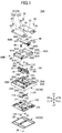
Fig. 1 is an exploded perspective view of a power generation switch. -
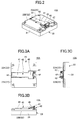
Fig. 2 is a perspective view of the power generation switch of the first embodiment. -
Fig. 3A is a plane view of the power generation switch. -
Fig. 3B is a front view of the power generation switch. -
Fig. 3C is a right side view of the power generation switch. -
Fig. 4 is a perspective view of the power generation switch, where a top cover thereof is removed. -
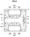
Fig. 5 is a plane view of the power generation switch, where a top cover thereof is removed. -
Fig. 6 is a perspective view of a main body of a case of the power generation switch. -
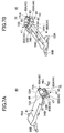
Fig. 7A is a perspective view of a switch unit of the power generation switch. -
Fig. 7B is another perspective view of the switch unit of the power generation switch. -
Fig. 8 is an exploded perspective view of the switch unit of the power generation switch. -
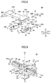
Fig. 9 is a perspective view of a magnet unit of the switch unit. -
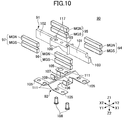
Fig. 10 is an exploded perspective view of the magnet unit. -
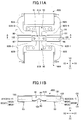
Fig. 11A is a plane view of a coil unit and a magnet unit for illustrating a principal of power generation in the power generation switch. -
Fig. 11B is a cross sectional view in A-A ofFig. 11A . -
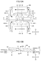
Fig. 12A is another plane view of a coil unit and a magnet unit for illustrating a principal of power generation in the power generation switch. -
Fig. 12B is a cross sectional view in A-A ofFig. 12A . -
Fig. 13A is another plane view of a coil unit and a magnet unit for illustrating a principal of power generation in the power generation switch. -
Fig. 13B is a cross sectional view in A-A ofFig. 13A . -
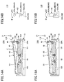
Fig. 14A is a cross sectional view of the power generation switch for illustrating operations thereof. -
Fig. 14B is an enlarged view of an operational element inFig. 14A . -
Fig. 15A is another cross sectional view of the power generation switch for illustrating operations thereof. -
Fig. 15B is an enlarged view of an operational element inFig. 15A . -
Fig. 16A is another cross sectional view of the power generation switch for illustrating operations thereof. -
Fig. 16B is an enlarged view of an operational element inFig. 16A . -
Fig. 17A is another cross sectional view of the power generation switch for illustrating operations thereof. -
Fig. 17B is an enlarged view of an operational element inFig. 17A . -
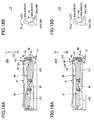
Fig. 18A is another cross sectional view of the power generation switch for illustrating operations thereof. -
Fig. 18B is an enlarged view of an operational element inFig. 18A . -
Fig. 19A is another cross sectional view of the power generation switch for illustrating operations thereof. -
Fig. 19B is an enlarged view of an operational element inFig. 19A . -
Fig. 20 is a perspective view of the power generation switch of the second embodiment. -
Fig. 21 is an exploded perspective view of the power generation switch of the second embodiment. -
Fig. 22 is a perspective view of the power generation switch of the third embodiment. -
Fig. 23 is an exploded perspective view of the power generation switch of the third embodiment. - In the following, embodiments will be described with reference to accompanying drawings as non-limiting examples.
- Additionally, in the embodiments and drawings, identical reference numerals will be applied to elements or the like that have substantially similar functions and configurations to those in another embodiment or another drawing, and descriptions thereof may be omitted. Also, the drawings are not for illustrating relative ratio between elements or assemblies unless otherwise indicated. Therefore, a specific size may be determined by one skilled in the art taking account of non-limiting examples described below.
- Also, the embodiments described below are non-limiting examples, where features disclosed in the embodiments or combinations thereof are not always essential to the present invention.
-
Fig. 1 - Fig. 3 are diagrams illustrating a power generation switch of an embodiment. -
Fig. 1 is an exploded perspective view of thepower generation switch 10A, andFig. 2 is a perspective view of thepower generation switch 10A.Fig. 3A is a plane view of thepower generation switch 10A,Fig. 3B is a front view of thepower generation switch 10A andFig. 3C is a right side view of thepower generation switch 10A. - The
power generation switch 10A includes acase 20, aswitch unit 40,coil units magnet unit 90, ayoke driving mechanism 110 and a circuit substrate (substrate) 120. - The
power generation switch 10A performs power generation using thecoil units magnet unit 90 when theswitch unit 40 is operated, and thepower generation switch 10A performs communication through thesubstrate 120 using the generated power. In the following, a configuration of thepower generation switch 10A will be described. - The
case 20 is a resin molded part that includes amain boy 21, atop cover 22, and abottom cover 23. - As shown in an enlarged view of
Fig. 6 , themain body 21 of thecase 20 includes a switchunit mounting part 25, coilunit mounting parts unit mounting part 27, erectingwalls walls -
Shaft receiving parts unit mounting part 25. Also, the erectingwalls slanted walls unit mounting part 25. Also, screw holes 31 are formed at four corners of themain body 21. -
Fig. 4 andFig. 5 are diagrams illustrating themain body 21 including theswitch unit 40, thecoil units magnet unit 90, theyoke driving mechanism 110, and the like. - The
switch unit 40 is mounted on the switchunit mounting part 25. Thecoil unit 80A is mounted on the coilunit mounting part 26A and thecoil unit 80B is mounted on the coilunit mounting part 26B. Themagnet unit 90 is mounted on the magnetunit mounting part 27. - The
top cover 22 is formed by a pair ofhalf bodies holes 34 are formed in thehalf bodies Screws 35 are inserted in the throughholes 34 to be screwed into screw holes 31 formed on themain body 21, thereby fixing thehalf bodies main body 21 of thecase 20. - An
arm space 33 is formed between thehalf bodies half bodies main body 21 of thecase 20. Theswitch unit 40 is mounted in thearm space 33. - The
bottom cover 23 is fixed at a back surface of themain body 21 of thecase 20 after abase element 114 and asubstrate 120 are mounted on the back surface of themain body 21. - The
base element 114 and themagnet unit 90 are fixed at themain body 21 with by using fixing screws 112 (described later). Thesubstrate 120 is fixed at themain body 21 by using the fixing screws 123. - Through
holes 122 are formed at predetermined positions of thesubstrate 120, and screw holes (not shown) corresponding to the throughholes 122 are formed on the back surface of themain body 21. Thesubstrate 120 is fixed at a back surface of themain body 21 by inserting the fixingscrews 123 in the throughholes 122 to be screwed in screw holes formed in the buck surface of themain body 21. -
Electronic assemblies 121 for forming a high frequency communication circuit are mounted on thesubstrate 120. Thesubstrate 120 is electrically connected with thecoils coil units main body 21 via theterminals 83. - Therefore, induced electromotive force generated by the
coils substrate 120, and theelectronic assemblies 121 are operated with the power of the induced electromotive force. When the high frequency communication circuit is operated, for example, thepower generation switch 10A transmits radio wave in 2.4 GHz band to an electric apparatus (e.g. light equipment). - As described above, the
entire case 20 is formed as a rectangle-shaped chassis when thetop cover 22 is mounted on a front side of themain body 21 and thebottom cover 23 is mounted on a back side of themain body 21. Also, in assembling, alever element 41 of theswitch unit 40 is projected from a top surface of thetop cover 22 as shown inFig. 2 and Fig. 3A - Fig. 3C . - A pushing
part 49 projected from thetop cover 22 of theswitch unit 40 is pushed to drive thepower generation switch 10A. As described below, in response to the pushingpart 49 being further pushed, the induced electromotive force is generated in thecoils - In the following, the
switch unit 40 will be described. -
Fig. 7A, Fig. 7B andFig. 8 are diagrams illustrating theswitch unit 40. Theswitch unit 40 includes alever element 41, anoperational element 42, a connectingshaft 43, a guidingshaft 44, aroller 46 and atorsion spring 47. - The
lever element 41 is a resin molded part in whichshaft parts shaft bearing parts parts stoppers lever element 41 is approximately rectangular in a plane view. Additionally, thelever element 41 may not be formed as the resin molded part, and a material thereof may be other than the resin such as metal. - The
shaft parts lever element 41. Theshaft parts lever element 41. - The
shaft parts shaft receiving parts main body 21 when theswitch unit 40 is mounted in themain body 21. Theswitch unit 40 is rotatable in themain body 21 when theshaft parts shaft receiving parts - The
shaft bearing parts shaft parts shaft bearing parts holes shaft bearing parts shaft 43 that is coupled to theoperational element 42 is inserted through the throughholes - The
operational element 42 is a resin molded part in which aroller mounting part 60, a first throughhole 61, a second throughhole 62, andprojections 63 are included. Additionally, theoperational element 42 may not be formed as the resin molded part, and a material thereof may be other than the resin such as metal. - In the
operational element 42, aroller mounting part 60 and the second throughhole 62 are formed in lower side thereof while the first throughhole 61 is formed in upper side thereof inFig. 8 . - The
roller mounting part 60 is a concave portion in which theroller 46 is mounted. The guidingshaft 44 is inserted through the second throughhole 62 after theroller 46 mounted in theroller mounting part 60, thereby coupling theroller 46 to theoperational element 42. Theroller 46 is formed so that a part of theroller 46 is projected from one end of theoperational element 42 when theroller 46 is mounted in theoperational element 42. - The
operational element 42, configured as described above, is mounted by theshaft bearing parts lever element 41, and theoperational element 42 is coupled to thelever element 41 by inserting the connectingshaft 43 through the throughholes hole 61. Thus, when theoperational element 42 is coupled to thelever element 41, theoperational element 42 is rotatable about the connectingshaft 43 to turn round with respect to thelever element 41 in direction indicated by arrows B1 and B2 shown inFig. 7A . - The connecting
shaft 43 and the guidingshaft 44 includeflange parts groove parts - When the connecting
shaft 43 is inserted through the throughholes hole 61, theflange part 66 abuts against a side wall of theshaft baring part 51A while thegroove part 67 is at a position outside (in direction of Y1) of theshaft bearing part 51B. A split washer 71 (seeFig. 8 ) is attached to thegroove part 67. Thus, the connectingshaft 43 can be prevented from being slipped off from thelever element 41, thereby preventing theoperational element 42 from being separated from thelever element 41. - Further, when the connecting
shaft 43 is held by thelever element 41,insertion parts shaft 43 projects outward from theshaft bearing parts - Also, when the guiding
shaft 44 is inserted through the second throughhole 62 and theroller 46, theflange part 69 abuts against a side wall of theoperational element 42 while thegroove part 70 projects outward from the other side wall of theoperational element 42 in the direction Y1. A split washer 72 (seeFig. 8 ) is attached to thegroove part 70. Thus, the guidingshaft 44 can be prevented from being slipped off from theoperational element 42, thereby preventing theroller 46 from being separated from theoperational unit 42. - Further, when the guiding
shaft 44 is held by theoperational part 42, engagingparts shaft 44 project outward from both side walls of theoperational element 42. - In the
torsion spring 47, windingparts end parts part 75 are integrally formed by using a wire rod for spring. Thetorsion spring 47, with theoperational element 42, is attached to thelever element 41 when theoperational element 42 is attached to thelever element 41. - When the
torsion spring 47 is attached to thelever element 41, the windingparts torsion spring 47 are inserted in theinsertion parts shaft 43. Also, theend part 74A is hooked by the hookingpart 53A of thelever element 41 while theend part 74B is hooked by the hookingpart 53B. Further, the connectingpart 75 is engaged by thegroove part 64 formed on theoperational element 42. - When the
torsion spring 47 is disposed between thelever element 41 and theoperational element 42, thetorsion spring 47 elastically biases theoperational element 42 inward (direction of arrow B2). However, theprojections 63 projected toward both side are formed andprojections 51A-1 and 52B-1 are formed in lower side (in Z2 direction) of theshaft bearing parts operational element 42. When theprojections 63 abut theprojections 51A-1 and 52B-1, theoperational element 42 is prevented from further pivoting inward (in B2 direction). - When the
projections 63 abut theprojections 51A-1 and 52B-1, theoperational element 42 extends approximately perpendicular to thelever element 41. - The
switch unit 40, configured as described above, is mounted on themain body 21 when theshaft parts lever element 41 are held by theshaft receiving parts main body 21. In mounting operation of theswitch unit 40 on themain body 21, acoil spring 48 is disposed between a lower surface of thelever element 41 and themain body 21. - The
coil spring 48 elastically biases thelever element 41 so as to separate from a bottom surface of themain body 21 by pivoting about theshaft parts stoppers lever element 41. When thestoppers half bodies lever element 41 is prevented from further pivoting. - In the following, the
coil units - As shown in
Fig. 1 ,Fig. 5 andFig. 11A , thecoil units coils cores coils cores - The
coils cores - The
coil units unit mounting parts main body 21. When being mounted, thecoils main body 21. - Also, when being mounted, certain portions of the
cores magnet unit 90 is disposed between thecoil units - Additionally, in the descriptions given below, portion of the core 82A of the
coil unit 80A, which faces the magnet unit 90 (magnet mounting part 101) may be referred to as facingportions 82A-1 and 82A-2. Also, portion of the core 82B of thecoil unit 80B, which faces the magnet unit 90 (magnet mounting part 102) may be referred to as facingportions 82B-1 and 82B-2. - In the following, the
magnet unit 90 will be described. -
Fig. 9 andFig. 10 are diagrams illustrating themagnet unit 90. Themagnet unit 90 includes ayoke 91, aspring element 92, and magnet pairs 94 - 97. - The
magnet unit 90 is disposed at approximate center of themain body 21, where direction of arrows X1 and X2 corresponds to a longitudinal direction thereof. Also, themagnet unit 90 is disposed in lower side of the disposedswitch unit 40. - That is, when the
switch unit 40 and themagnet unit 90 are disposed in themain body 21, theswitch unit 40 overlaps (disposed at a position in Z1 direction) themagnet unit 90. - The
yoke 91 is an approximate prism-shaped element made of magnet metal. Aspring fixing part 99 is formed at center of theyoke 91, andmagnet mounting parts spring fixing parts 99. In the present embodiment, although, thespring fixing part 99 and themagnet mounting parts spring fixing part 99 may be formed separately from themagnet mounting parts spring fixing part 99 is coupled to themagnet mounting parts - A triangular
concave portion 100 is formed in thespring fixing part 99, where a shape of the triangularconcave portion 100 is approximate triangle in a front view (viewed in Y2 direction). Screw holes 117 having certain heights (in Z1-Z2 direction) are formed at both sides of triangularconcave portion 100 of thespring fixing part 99. - The
magnet mounting parts spring fixing part 99. The magnet pairs 94 - 97 are fixed at themagnet mounting parts - A
hook 103 is formed at front end (end in X1 direction) of themagnet mounting part 101. Theoperational element 42 of theswitch unit 40 is engaged with thehook 103. In the present embodiment, thehook 103 is formed as a step portion. However, as described below, thehook 103 may be formed as a different shaped portion as long as it can be engaged with theoperational element 42. - The
spring element 92 is formed through a pressing operation on a spring plate. In thespring element 92, abase part 105, atriangle spring part 106, aholder part 107 are integrally formed. - The
base part 105 is fixed at themain body 21. A pair ofbase parts 105 is disposed being separated in directions of arrows Y1 and Y2. Throughholes 111 are formed inrespective base parts 105. Positions of the throughholes 111 correspond to the positions of the throughholes 32 formed in themain body 21. - The
triangle spring part 106 is provided for connecting respective center positions of the pair of thebase parts 105. Therefore, in a plane view (viewed in direction of arrow Z1), thebase part 105 and thetriangle spring part 106 form approximate "H" shape. - A cross section of the
triangle spring part 106 is approximately rectangular. Theholder parts 107 are formed at center of thetriangle spring part 106 extending toward both sides of thetriangle spring part 106. Also, throughholes 109 are formed in theholder parts 107. - The
spring fixing part 99 of theyoke 91 is fixed at theholder part 107. When theyoke 91 is fixed at thespring element 92, theyoke 91 is mounted in thespring element 92 in a manner such that the triangularconcave portion 100 and thetriangle spring part 106 are engaged with each other, or thespring fixing part 99 is engaged with theholder part 107. When being mounted, the position of the throughhole 109 formed in theholder part 107 and the position of thescrew hole 117 formed in thespring fixing part 99 coincide. - Then, the fixing
screw 108 is inserted from lower side of theholder part 107 penetrating through the throughhole 109 and thescrew hole 117 formed in thespring fixing part 99. Thus, theyoke 91 is fixed at thespring element 92. When theyoke 91 is fixed at thespring element 92, a longitudinal direction of theyoke 91 is perpendicular to a direction in which thetriangle spring part 106 extends. - Additionally, in the descriptions given below, in a case where the
switch unit 40 and themagnet unit 90 are mounted in themain body 21, the longitudinal direction (direction of arrows X1 and X2) of theyoke 91 may be referred to as a depth direction, and the direction (direction of arrows Y1 and Y2) in which thetriangle spring part 106 extends that is perpendicular to the depth direction may be referred to as width direction and a direction (direction of arrows Z1 and Z2) perpendicular to both the depth direction and the width direction may be referred to as up-down direction. - Specifically, in the depth direction, a direction (direction of X1) toward the
hook 103 may be referred to as a forward direction, and a direction (direction of X2) toward theshaft receiving part coil unit 80A may be referred to as a right direction, and a direction (direction of Y1) toward thecoil unit 80B may be referred to as a left direction. Further, in the up-down direction, a direction (direction of Z2) in which thelever element 41 is pushed to move may be referred to as a down direction, and a direction (direction of Z1) in which thelever element 41 having been pushed returns in response to release of the pressure may be referred to as up direction. - The magnet pairs 94 -97 are formed by a pair of magnets MGN and MGS whose polarities opposite to each other. In the respective magnet pairs 94 - 97, the magnets MGN and MGS are arranged alongside each other, where the magnet MGN is positioned at a portion in the up direction and the magnet MGS is positioned at a portion in the down direction.
- The
magnet pair 94 is fixed at a portion in direction of Y2 of themagnet mounting part 101. Themagnet pair 95 is fixed at a portion in direction of Y2 of themagnet mounting part 102. Themagnet pair 96 is fixed at a portion in direction of Y1 of themagnet mounting part 101. Themagnet pair 97 is fixed at a portion in direction of Y1 of themagnet mounting part 102. - For example, the magnet pairs 94 - 97 are fixed at the
magnet mounting parts - The
magnet unit 90 configured as described above is fixed at themain body 21 by using fixingscrews 112 and the base element 114 (seeFig. 1 ). - As shown in
Fig. 1 , thebase element 114 is disposed on the back side surface of themain body 21. Thebase element 114 is made of metal or resin having strength for holding themagnet unit 90. Screw holes 115 are formed in thebase element 114 at positions corresponding to the positions of the throughholes 32 and the throughholes 111. - When the
magnet unit 90 is mounted in the magnetunit mounting part 27 of themain body 21, positions of the throughholes 111 formed in thebase part 105 and the throughholes 32 formed in themain body 21 coincide. - Then, the
base element 114 is arranged on the back surface of themain body 21. At this time, thebase element 114 is positioned so that the positions of the screw holes 115 formed in thebase element 114 coincide with the positions of the throughholes base part 105. - In this way, positioning of the
main body 21, themagnet element 90 and thebase element 114 is performed, and the fixingscrews 112 penetrate the throughholes Fig. 1 ). Thus, themagnet unit 90 is fixed at themain body 21. - Here, movement of the
yoke 91 when themagnet unit 90 is fixed at themain body 21 will be described. - The
yoke 91 is attached to thetriangle spring part 106 formed in thespring element 92. Also, thetriangle spring part 106 extends in the width direction (direction of arrows Y1 and Y2). Therefore, as shown inFig. 9 , theyoke 91 is prevented from rotating (rolling in direction of arrows E1 and E2 shown inFig. 9 ) about the axis in the depth direction (direction of arrows X1 and X2), and rotating (yawing in direction of arrows D1 and D2 shown inFig. 9 ) about the axis in the up-down direction (direction of arrows Z1 and Z2). - On the other hand, the
yoke 91 is allowed to rotate (pitching shown as arrows C1 and C2) about the axis in the width direction (direction of arrows Y1 and Y2) due to elastic deformation of thetriangle spring part 106. Hence, the magnet pairs 94 - 97 arranged on theyoke 91 can also rotate about the axis in the width direction (rotation in direction of arrows C1 and C2). - As described above, the
yoke 91, supported by thespring element 92, is rotatable in the direction of arrows C1 and C2 shown inFig. 9 . However, the elastic deformation of thetriangle spring part 106 does not occur in a state where theyoke 91 is horizontally placed that is, theyoke 91 is parallel with the bottom surface of themain body 21. - On the contrary, when external force is applied to the
yoke 91 to rotate the yoke in the direction of arrow C1 or arrow C2, the elastic deformation of thetriangle spring part 106 is caused, and thereby elastic force is accumulated in thetriangle spring part 106. The elastic force serves to have theyoke 91 return to a position before rotated. - In the following, the
yoke driving mechanism 110 will be described. - The
yoke driving mechanism 110 includes anoperational element 42 forming a part of theswitch unit 40, the erectingwalls walls main body 21. - As shown in
Fig. 14A , in theoperational element 42, theroller 46 is disposed at a portion in theyoke 91 facing thehook 103. Theroller 46 is engaged with thehook 103 of theyoke 91 when the pushingpart 49 of thelever element 41 is pushed. - After the
operational element 42 is engaged with thehook 103, theyoke 91 rotates in the direction of C1 since thehook 103 is pushed by theoperational element 42 in response to further pushing operation of the lever element 41 (seeFig. 16 ). At this time, in thespring element 92 supporting theyoke 91, the elastic force is accumulated according to the elastic deformation of thetriangle spring part 106 due to the rotation of theyoke 91. - As shown in
Fig. 14B , the erectingwalls slanted walls parts shaft 44 formed in theoperational element 42. - The erecting
walls main body 21. Also, the slantedwalls engaging part 68A engages with the erectingwall 28A and theslanted walls 29A, while theengaging part 68B engages with the erectingwall 28B and the slantedwalls 29B. - The erecting
wall 28A and theslanted wall 29A are sequentially connected, and the erectingwall 28B and theslanted wall 29B are sequentially connected. Therefore, theengaging part 68A moves between the erectingwall 28A and theslanted walls 29A, while theengaging part 68B moves between the erectingwall 28B and the slantedwalls 29B. - As describe above, the
operational element 42 is biased by thetorsion spring 47 in the direction of the arrow B2. Therefore, the engagingparts walls slanted walls parts walls slanted walls operational element 42 is moved in the up-down direction (direction of Z1 and Z2) according to the rotation of thelever element 41. - In a case where the engaging
parts walls operational element 42 is kept to be approximately perpendicular to thelever element 41. Also, in a case where theoperational element 42 is approximately perpendicular to thelever element 41, theroller 46 is kept to be facing thehook 103. - On the other hand, when the
operational element 42 moves in the down direction (direction of Z2) while the engagingparts walls parts walls parts main body 21. - As described above, the
operational unit 42 is coupled to thelever element 41 through the connectingshaft 43. Therefore, theoperational element 42 rotates in direction of arrow B1 shown inFig. 14B because the guidingshaft 44 is biased in the forward direction of themain body 21. - When the
operational element 42 rotates in the direction B1, theroller 46 moves in a direction separating from thehook 103. Upon theoperational element 42 rotating in direction of B1, up to a predetermined position, theroller 46 separates from thehook 103. In response to theroller 46 separating from thehook 103, theyoke 91 quickly rotates in the C2 direction due to the elastic force accumulated in thetriangle spring part 106. - As described above, in response to a pushing operation of the
lever element 41, theyoke driving mechanism 110 have the operational element 42 (roller 46) engage with theyoke 91 to rotate theyoke 91 in the C1 direction, and theyoke driving mechanism 110 have the roller 460 separate from thehook 103 upon thelever element 41 being further pushed to be moved up to the predetermined position, thereby rotating theyoke 91 in the C2 direction. - In the following, a power generation principal of the
power generation switch 10A of the present embodiment will be described. -
Fig. 11A - Fig. 13B are diagrams illustrating the power generation principal of thepower generation switch 10A. InFig. 11A - Fig. 13B , thecoil units magnet unit 90 are shown being enlarged for convenience of explanation. - Also,
Fig. 11A ,Fig. 12A andFig. 13A are plane views of thecoil units magnet unit 90, whileFig. 11B ,Fig. 12B andFig. 13B are cross-sectional views in A-A ofFig. 11A ,Fig. 12A andFig. 13A . Therefore, inFig. 11B ,Fig. 12B andFig. 13B , the magnet pairs 94 and 95 and the core 82A of thecoil unit 80A are disposed behind the yoke 91 (magnet pairs 94 and 95 andcoil unit 80A are shown with dotted lines). - Additionally, in the
power generation switch 10A, operations of the magnet pairs 94 and 95 disposed in right side of the A-A are the same as those of the magnet pairs 96 and 97 disposed in left side of the A-A. Therefore, inFig. 11B ,Fig. 12B andFig. 13B , the operations of the magnet pairs 94 and 95 are described while descriptions of the operations of the magnet pairs 96 and 97 are omitted (reference numerals related to the magnet pairs 96 and 97 are shown in parentheses in the descriptions). -
Fig. 11A and Fig. 11B are diagrams illustrating thecoil unit 80A (80B) of themagnet unit 90 before operation. Theyoke 91 is placed horizontally in a state before the operation. - Also, in the state before the operation, the facing
portion 82A-1 (82B-1) of thecore 82A (82B) faces a boundary of the magnets MGN and MGS of the magnet pair 94 (96). Similarly, the facingportion 82A-2 (82B-2) of thecore 82A (82B) faces a boundary of the magnets MGN and MGS of the magnet pair 95 (97). - Additionally, a side of the magnet MGN facing the facing
portions 82A-1, 82A-2, 82B-1 and 82B-2 is the positive electrode (N). Also, a side of the magnet MGS facing the facingportions 82A-1, 82A-2, 82B-1 and 82B-2 is the negative electrode (S). -
Fig. 12A and Fig. 12B are diagrams illustrating thecoil unit 80A (80B) of themagnet unit 90 with thehook 103 being pushed to rotate theyoke 91 in a direction of arrow C1 (hereinafter, a state shown inFig. 12A and Fig. 12B is referred to as an operation state). - When the
yoke 91 rotates in the direction of arrow C1, the magnet pairs 94 (96) and 95 (97) fixed at theyoke 91 rotate accordingly. Also, when theyoke 91 rotates in the direction of arrow C1, the elastic deformation of thetriangle spring part 106 of themagnet unit 90 occurs, and the elastic force is accumulated. - In the operation state, as shown in
Fig. 12B , the magnet MGN of the magnet pair 94 (96) faces the facingportion 82A-1 (82B-1) of thecore 82A. Also, the magnet MGS of the magnet pair 95 (97) faces the facingportion 82A-2 (82B-2) of thecore 82A. - The polarity of the magnet MGN magnetically connected to the facing
portion 82A-1 (82B-1) is opposite to that of the magnet MGS magnetically connected to the facingportion 82A-2 (82B-2). Therefore, magnetic flux from the facingportion 82A-1 (82B-1) to the facingportion 82A-2 (82B-2) is generated in thecore 82A (82B) (magnetic fluxes are indicated by thick arrows inFig. 12A ). - Upon a pressure applied to the
yoke 91 in the operation state shown inFig. 12A and Fig. 12B being released, theyoke 91 instantaneously rotates in a direction of arrow C2 according to the elastic force having been accumulated in thetriangle spring part 106. When theyoke 91 rotates in the direction of arrow C2, theyoke 91 returns to be in the state before the operation. However, theyoke 91 does not exactly stops at a position corresponding to the state before the operation, but theyoke 91 further rotates in the direction of arrow C2 exceeding the position corresponding to the state before the operation due to inertia force as shown inFig. 13B (hereinafter the state shown inFig. 13B is referred to as an over moving state). - In the over moving state, as shown in
Fig. 13B , the magnet MGS of the magnet pair 94 (96) faces the facingportion 82A-1 (82B-1) of thecore 82A (82B). Also, the magnet MGN of the magnet pair 95 (97) faces the facingportion 82A-2 (82B-2) of thecore 82A (82B). - The polarity of the magnet MGS magnetically connected to the facing
portion 82A-1 (82B-1) is opposite to that of the magnet MGN magnetically connected to the facingportion 82A-2 (82B-2). Therefore, magnetic flux from the facingportion 82A-2 (82B-2) to the facingportion 82A-1 (82B-1) is generated in thecore 82A (82B) (magnetic fluxes are indicated by thick arrows inFig. 13A ). - As described above, in the
power generation switch 10A of the present embodiment, a direction of the magnetic flux of thecore 82A (82B) in the operation state is opposite to that in the over moving state. - Therefore, in the
power generation switch 10A of the present embodiment, upon the pressure applied to thehook 103 being released after theyoke 91 has moved to the position corresponding to the operation state, theyoke 91 instantaneously rotates in the direction of arrow C2 to move to a position corresponding to the over moving state due to the elastic force of thetriangle spring part 106. The magnetic flux of thecore 82A (82B) is inverted in accordance with the movement of the yoke 91 (magnetic pairs 94 - 97). Therefore, a significant change of the magnetic flux in thecore 82A (82B) occurs, thereby generating the induced electromotive force in thecoil 81A (81B) attached to thecore 82A (82B). - Additionally, in the present specification, "instantaneous movement of the
yoke 91" means the movement of theyoke 91 that can generate the induced electromotive force in thecoil 81A (81B). - In the following, operations of the
power generation switch 10A based on the aforementioned principal of the power generation will be described. -
Fig. 14A - Fig. 19B are diagrams illustrating the operations of thepower generation switch 10A.Fig. 14A, Fig. 15A ,Fig. 16A, Fig. 17A ,Fig. 18A and Fig. 19A are cross sectional views in the depth direction (direction of X1 and X2), whileFig. 14B, Fig. 15B ,Fig. 16B, Fig. 17B ,Fig. 18B and Fig. 19B are diagrams illustrating operations of theoperational element 42 with its enlarged views. -
Fig. 14A and Fig. 14B show thepower generation switch 10A in the state before the operation. - In the state before operation, the
lever element 41 has been moved (turned about theshaft parts coil spring 48 in a direction (direction of Z1) so as to separate from the bottom of themain body 21. Also, theoperational element 42 of theyoke driving mechanism 110 is placed so as to be perpendicular to thelever element 41 and directed downward (direction of Z2). - Further, as shown in
Fig. 14A , theroller 46 is separated from thehook 103. Thus, any external force is not applied to theyoke 91, where theyoke 91 is kept to be placed horizontally. Moreover, the elastic deformation of thetriangle spring part 106 of thespring element 92 does not occur because theyoke 91 is placed horizontally. Further, as shown inFig. 14B , the engagingparts shaft 44 engage with the erectingwalls main body 21. - Upon the user pressing the pushing
part 49 of theswitch unit 40 of thepower generation switch 10A in the state before the operation, thelever element 41 turns downward (direction of Z2) about theshaft parts Fig. 14A , the operational force of the user is shown as arrow F. - When the
lever element 41 turns, theoperational element 42 moves toward thehook 103. According to the movement of theoperational element 42, the engagingparts walls parts walls operational element 42 stably moves toward thehook 103. - Subsequently, the
roller 46 of theoperational element 42 engages with thehook 103 in accordance with the movement of thelever element 41.Fig. 15A and Fig. 15B are diagrams illustrating thepower generation switch 10A in which theroller 46 engages with thehook 103. In this state, the engagingparts walls - Upon the user further pressing the pushing
part 49, theoperational element 42 moves downward (direction of Z2) to be pressed against thehook 103. When thehook 103 is pressed, theyoke 91 rotates in the direction of C1. - In response to the
yoke 91 rotating in the direction of C1, the magnetic fluxes shown as thick arrows inFig. 12A are generated in thecores power generation switch 10A is in the operation state. -
Fig. 16A, Fig. 16B, Fig. 17A and Fig. 17B are diagrams illustrating thepower generation switch 10A in the operation state. Specifically,Fig. 16A and Fig. 16B show theengaging parts walls slanted walls - The erecting
walls main body 21. Therefore, theoperational element 42 does not rotate about the connectingshaft 43 during theengaging parts shaft 44 move along the erectingwalls roller 46 to be engaged with thehook 103. -
Fig. 17A and Fig. 17B show theengaging parts walls - Upon the
lever element 41 being pressed while the engagingparts walls parts walls parts main body 21. - When the engaging
parts main body 21, theoperational element 42 rotates in a direction shown as arrow B1, and accordingly theroller 46 separates from thehook 103. -
Fig. 18A and Fig. 18B show theroller 46 before separating from thehook 103. Upon thelever element 41 shown inFig. 18A and 18B being further pressed, the engagingparts walls operational element 42 rotates in the direction of B1 accordingly, thereby separating theroller 46 from thehook 103. -
Fig. 19A and Fig. 19B show theroller 46 separated from thehook 103. - When the
roller 46 is separated from thehook 103, a pressure in the direction of arrow C1 applied to theyoke 91 is released, and theyoke 91 instantaneously rotates in the direction of C2 due to the elastic force accumulated in thetriangle spring part 106. - When the
yoke 91 rotates in the direction of C2, the magnet MGS of the magnet pairs 94 and 96 face the facingportions 82A-1 and 82B-1 of thecores Fig. 13B and the magnet MGN of the magnet pairs 95 and 97 face the facingportions 82A-2 and 82B-2 of thecores Fig. 13A are generated in thecores power generation switch 10A is in the over moving state. - As described above, the direction of the magnetic fluxes in the
cores yoke 91 instantaneously moves from the position corresponding to the operation state to the position corresponding to the over moving state due to the elastic force of thetriangle spring part 106. Therefore, the significant changes of the magnetic flux in thecores yoke 91, thereby generating the induced electromotive forces in thecoils - Additionally, the
yoke 91 having moved to the position corresponding to the over moving state returns to the position corresponding to the state before the operation (placed horizontally) due to the elastic force of thespring element 92. - As described above, the
power generation switch 10A of the present embodiment generates power by driving theyoke 91, in which the magnet pairs 94 - 97 are arranged, through theyoke driving mechanism 110. Themagnet unit 90 including theyoke 91 and the magnet pairs 94 - 97 can be more miniaturized and can be made thinner in comparison to a conventional power generator including a motor, etc., and accordingly thepower generation switch 10A can be more miniaturized and made thinner. - Also, since the
yoke driving mechanism 110 for driving theyoke 91 is formed by the connectingshaft 43 attached to thelever element 41 and the erectingwalls slanted walls main body 21, a number of assemblies can be reduced and a configuration can be simplified, thereby reducing a production cost of thepower generation switch 10A. - In the following, the power generation switches 10B and 10C respectively corresponding to a second embodiment and a third embodiment will be described.
-
Fig. 20 andFig. 21 are diagrams illustrating thepower generation switch 10B corresponding to the second embodiment. Also,Fig. 22 and Fig. 23 are diagrams illustrating thepower generation switch 10C corresponding to the third embodiment. Additionally, inFig. 20 - Fig. 23 , identical reference numerals will be applied to elements or the like that correspond to those in the embodiment shown inFig. 1 - Fig. 19B , and descriptions thereof may be omitted. - First, the
power generation switch 10B of the second embodiment will be described with reference toFig. 20 andFig. 21 . -
Fig. 20 is a perspective view of thepower generation switch 10B.Fig. 21 is an exploded perspective view of main parts of thepower generation switch 10B. Additionally, the present embodiment is characterized in theswitch unit 40A, whereas other elements are configured similarly to thepower generation switch 10A of the first embodiment. Therefore, inFig. 21 , mainly elements constituting theswitch unit 40A are shown, whereas other elements may be omitted. - The
switch unit 40A includes aswitch button 130, aroller 131,coil springs spring holders - The
switch button 130 is pressed by the user. Hence, theswitch button 130 moves in up-down direction (direction of Z1 and Z2) in thecase 20. - The
roller 131 is coupled to a guidingshaft 132. Theroller 131 is disposed at a center of the guidingshaft 132, where both sides of the guidingshaft 132 respectively form engagingparts walls slanted walls coil springs shaft 132. - The coil springs 134A and 134B extend in the depth direction (direction of X1 and X2) . The coil springs 134A and 134B are held in the
spring holders -
Spring mounting parts spring holders parts spring mounting parts - When the
coil springs spring holders coil springs spring mounting parts Edge portions coil springs claw parts shaft 132 connected with the front ends of thecoil springs spring mounting parts - A pair of the
spring holders main body 21, where themagnet unit 90 is placed between the spring holders. When thespring holders main body 21, theroller 131 faces thehook 103 and the engagingparts walls top cover 22 is mounted on themain body 21, theswitch button 130 engage with the engagingparts - In the
power generation switch 10B of the present embodiment, upon theswitch button 130 being pressed, theswitch button 130 presses the engagingparts shaft 132 expands thecoil springs coil springs - In response to the
switch button 130 being pressed, theroller 131 moves downward. At this time, the guidingshaft 132 is pressed against the erectingwalls coil springs parts shaft 132 are moved and kept to be engaged with the erectingwalls roller 131 can be moved stably toward thehook 103. - In response to the
switch button 130 being pressed, theroller 131 abuts thehook 103 and presses thehook 103 downward. Thus, theyoke 91 in the state before the operation starts to rotate, and thepower generation switch 10B is transitioned into the operation state. - In response to the
switch button 130 being further pressed, the engagingparts walls shaft 132. Therefore, theroller 131 is moved (biased) in forward direction (direction of X1) because the engagingparts walls - When the
switch button 130 is pressed further, theroller 131 separates from thehook 103. Thus, theyoke 91 instantaneously moves to the position corresponding to the over moving state due to the elastic force accumulated in thespring element 92, and the power generation is performed in thecoil units roller 131 moves to the position corresponding to the state before the operation due to the elastic force accumulated in thecoil springs - In the
power generation switch 10B of the second embodiment, only theswitch button 130 projects from thetop cover 22. Therefore, a compact configuration of thepower generation switch 10B, especially in top surface of thetop cover 22, can be achieved. - In the following, the
power generation switch 10C corresponding to the third embodiment will be described with reference toFig. 22 and Fig. 23 . -
Fig. 22 is a perspective view of thepower generation switch 10C.Fig. 23 is an exploded perspective view of main parts of thepower generation switch 10C. Additionally, the present embodiment is characterized in theswitch unit 40B, whereas other elements are configured similarly to thepower generation switch 10A of the first embodiment. Therefore, inFig. 23 , mainly elements constituting theswitch unit 40B are shown, whereas other elements may be omitted. - The
switch unit 40B includes aswitch button 150, aroller 151, aroller holding element 152 andcoil springs - Similarly to the second embodiment, the
switch button 150 is pressed by the user and moves up-down direction (in direction of Z1 and Z2). - The
roller 151 is coupled to theroller holding element 152. Theroller 151 is disposed at a center of theroller holding element 152. Both sides of a roller holding portion of theroller holding element 152 respectively form engagingparts parts walls slanted walls switch button 150. - Also, both ends of the
roller holding element 152 are connected with one side ends of thecoil springs coil springs - A left side (direction of Y1) end of the
coil spring 153A is connected with theroller holding element 152, while a right side (direction of Y2)end 155A thereof is connected with a mountingpin 156A disposed in themain body 21. Also, a right side (direction of Y2) end of thecoil spring 153B is connected with theroller holding element 152, while a left side (direction of Y1)end 155B is connected with a mountingpin 156B disposed in themain body 21. - Further, a groove part 157 is formed at a portion of the
main body 21 facing theroller holding element 152 and thecoil springs roller holding element 152 and thecoil springs - When the
switch unit 40B is mounted in themain body 21, theroller 151 faces thehook 103 of theyoke 91, theroller holding element 152 and thecoil springs engaging part walls - The
roller holding element 152 and thecoil springs switch unit 40B is mounted in themain body 21, theroller holding element 152 and thecoil springs main body 21. - The mounting pins 156A and 156B are formed at positions deviated from positions of the erecting
walls slanted walls switch unit 40B being mounted in themain body 21, thecoil springs - Therefore, when the
switch unit 40B is mounted in themain body 21, the engagingparts walls coil springs - In the
power generation switch 10C of the present embodiment, in response to pressing theswitch button 150, theswitch button 150 presses the engagingparts roller holding element 152 moves downward (direction of Z2) while the movingroller holding element 152 expands thecoil springs coil springs - When the
roller holding element 152 moves downward, theroller 151 abuts thehook 103 and presses thehook 103 downward. Thus, theyoke 91 in the state before the operation starts to rotate, and thepower generation switch 10C is transitioned into the operation state. - In response to the
switch button 150 being further pressed, the engagingparts walls roller holding element 152. Therefore, theroller 151 is moved (biased) in forward direction (direction of X1) because the engagingparts walls - When the
switch button 150 is further pressed, theroller 151 separates from thehook 103. Thus, theyoke 91 instantaneously moves from the position corresponding to the operation state to the position corresponding to the over moving state, and the power generation is performed in thecoil units roller 151 moves to the position corresponding to the state before the operation due to the elastic force accumulated in thespring element 92. - Additionally, when the
switch button 150 is pressed to have theroller 151 separate from thehook 103, theroller holding element 152 and thecoil springs main body 21. Therefore, theroller 151 can be surely moved up to a position at which theroller 151 separates from thehook 103. - As described above, similarly to the
power generation switch 10B of the second embodiment, in the third embodiment, only theswitch button 150 projects from thetop cover 22. Therefore, a compact configuration of thepower generation switch 10C, especially in top surface of thetop cover 22, can be achieved. - Also, in the
power generation switch 10C of the third embodiment, since thespring holders power generation switch 10B of the second embodiment are not required, a number of assemblies can be reduced. - Further, since the
roller holding element 152 and thecoil springs main body 21, mounting space of theswitch unit 40B in themain body 21 can be reduced. - Although the invention has been described with respect to example embodiments for a complete and clear disclosure, the appended claims are not to be limited to the described embodiments but are to be construed as embodying all modifications and alternative constructions that may occur to one skilled in the art that fairly fall within the basic teaching set forth herein.
- For example, in the first embodiment, although the
roller 46 is disposed at a position where theoperational element 42 engage with thehook 103, theoperational element 42 may be directly engage with thehook 103 without disposing theroller 46. In this case, a shape of a portion of theoperational element 42 for engaging with thehook 103 may be spherical, curved, slanted, etc. , so as to improve the engagement performance of theoperational element 42 and thehook 103.
Claims (4)
- A power generation switch comprising:a case;a core, a coil being wound around the core;a magnet magnetically connected with the core;a yoke in which the magnet is disposed;an elastic element that supports the yoke and elastically deforms so as to deviate a position of the magnet from the core;a switch element that is operated to be moved; anda yoke driving mechanism that moves the yoke so that upon an engagement of the switch element and the yoke being released, the yoke moves between a first position and a second position due to elastic force of the elastic element, wherein first magnetic flux is generated by the core and the magnet when the yoke is at the first position and second magnetic flux different from the first magnetic flux is generated by the core and the magnet when the yoke is at the second position.
- The power generation switch according to claim 1, wherein
the yoke driving mechanism includes
an operational element provided in the switch element and configured to be able to move and engage with the yoke, and
a biasing element configured to bias the operational element so as to separate from the yoke upon the yoke moving to the second position. - The power generation switch according to claim 1, wherein the biasing element is a slanted wall formed in the case.
- The power generation switch according to claim 2 or claim 3, wherein the operational element includes a roller disposed at a position at which the yoke and the operational element engage.
Applications Claiming Priority (1)
| Application Number | Priority Date | Filing Date | Title |
|---|---|---|---|
| JP2015089037A JP6558048B2 (en) | 2015-04-24 | 2015-04-24 | Power switch |
Publications (2)
| Publication Number | Publication Date |
|---|---|
| EP3086344A1 true EP3086344A1 (en) | 2016-10-26 |
| EP3086344B1 EP3086344B1 (en) | 2018-10-10 |
Family
ID=55968891
Family Applications (1)
| Application Number | Title | Priority Date | Filing Date |
|---|---|---|---|
| EP16166540.1A Active EP3086344B1 (en) | 2015-04-24 | 2016-04-22 | Power generation switch |
Country Status (4)
| Country | Link |
|---|---|
| US (1) | US9754748B2 (en) |
| EP (1) | EP3086344B1 (en) |
| JP (1) | JP6558048B2 (en) |
| CN (1) | CN106067719B (en) |
Cited By (1)
| Publication number | Priority date | Publication date | Assignee | Title |
|---|---|---|---|---|
| CN111668043A (en) * | 2020-05-28 | 2020-09-15 | 深圳市晟瑞科技有限公司 | Self-generating switch |
Families Citing this family (25)
| Publication number | Priority date | Publication date | Assignee | Title |
|---|---|---|---|---|
| USD787450S1 (en) * | 2014-12-04 | 2017-05-23 | Omron Corporation | Electric relay |
| JP6643697B2 (en) * | 2015-09-24 | 2020-02-12 | ミツミ電機株式会社 | Electromagnetic transducer, actuator, and pump |
| CN106451993A (en) * | 2016-11-28 | 2017-02-22 | 广东顺德智勤科技有限公司 | Push type efficient power generator |
| CN117389172A (en) * | 2017-01-19 | 2024-01-12 | 广东易百珑智能科技有限公司 | Passive wireless control module |
| CN106876202B (en) * | 2017-03-21 | 2019-03-26 | 武汉领普科技有限公司 | The more key switches of self-generating wireless |
| CN108695101B (en) * | 2017-04-10 | 2019-08-30 | 施耐德电气(澳大利亚)有限公司 | Button switch |
| CN107170619B (en) * | 2017-06-08 | 2019-02-26 | 宁波公牛电器有限公司 | A power generating device and rocker switch |
| CN107681863B (en) * | 2017-11-07 | 2023-06-16 | 中国计量大学 | Mechanical Press Micro Energy Harvesting Device |
| KR101987929B1 (en) * | 2018-03-29 | 2019-06-12 | 주식회사 한세스 | Wireless switch for wiring appliance |
| CN112740522B (en) * | 2018-10-02 | 2023-11-07 | 阿尔卑斯阿尔派株式会社 | power generation device |
| FR3093874B1 (en) * | 2019-03-15 | 2021-04-16 | Commissariat Energie Atomique | electromagnetic device |
| CN110706963A (en) * | 2019-09-17 | 2020-01-17 | 宁波公牛电器有限公司 | A wireless control switch |
| WO2021051823A1 (en) * | 2019-09-17 | 2021-03-25 | 宁波公牛电器有限公司 | Self-power generation module and wireless control switch |
| CN110690804B (en) * | 2019-09-17 | 2021-04-27 | 宁波公牛电器有限公司 | A self-generating module and passive wireless switch |
| JP7533871B2 (en) * | 2020-01-15 | 2024-08-14 | ミネベアミツミ株式会社 | Vibration actuator and electronic device |
| US20210257896A1 (en) * | 2020-02-17 | 2021-08-19 | Dan Haronian | Movement and Vibration energy harvesting |
| JP7504624B2 (en) * | 2020-02-28 | 2024-06-24 | キヤノン株式会社 | Power generating element and device using the power generating element |
| EP4205270A4 (en) * | 2020-08-26 | 2025-06-04 | Propitious Technologies, LLC | Magnified linear power generation system |
| FR3122049B1 (en) * | 2021-04-15 | 2023-03-03 | Commissariat Energie Atomique | Electromagnetic device for converting mechanical energy into electrical energy |
| US12278537B2 (en) * | 2021-05-05 | 2025-04-15 | Enervibe Ltd. | Electromagnetic vibration and energy harvester |
| US11936269B2 (en) * | 2021-09-22 | 2024-03-19 | Apple Inc. | Haptic engine based on angular resonant actuator with pivot axis and mass center that differ |
| US20230246532A1 (en) * | 2022-02-03 | 2023-08-03 | Enervibe Ltd. | Electromagnetic Kinetic Energy Harvester |
| CN218215067U (en) * | 2022-10-28 | 2023-01-03 | 东莞市迪斐玛电子有限公司 | Self-generating wireless small switch and combined self-generating switch |
| CN121942127A (en) * | 2023-09-27 | 2026-04-28 | 克斯美库股份有限公司 | Self-generating device and cylinder device using same |
| US12413125B2 (en) * | 2023-10-12 | 2025-09-09 | Randy Questad | Reciprocating magnetic motor |
Citations (5)
| Publication number | Priority date | Publication date | Assignee | Title |
|---|---|---|---|---|
| JP2005102413A (en) | 2003-09-25 | 2005-04-14 | Asaba:Kk | Generator |
| US20080315595A1 (en) * | 2005-11-22 | 2008-12-25 | Schneider Electric Industries Sas | Stand-Alone Device for Generating Electrical Energy |
| US20130093540A1 (en) * | 2010-03-23 | 2013-04-18 | Zf Friedrichshafen Ag | Induction generator |
| EP2747111A1 (en) * | 2012-12-21 | 2014-06-25 | Eltako GmbH Schaltgeräte | Radio switch |
| US20140265640A1 (en) * | 2011-10-13 | 2014-09-18 | Zf Friedrichshafen Ag | Switching Module for a Switch, Switch, Method for Indicating an Actuation of a Switch and Method for Controlling a Device |
Family Cites Families (5)
| Publication number | Priority date | Publication date | Assignee | Title |
|---|---|---|---|---|
| US2832902A (en) * | 1956-09-17 | 1958-04-29 | John F Drescher | Impulse generator |
| DE10315765C5 (en) * | 2003-04-07 | 2021-03-11 | Enocean Gmbh | Use of an electromagnetic energy converter |
| JP5740897B2 (en) * | 2010-10-04 | 2015-07-01 | ミツミ電機株式会社 | Power generation device and switch |
| JP6155470B2 (en) * | 2011-12-09 | 2017-07-05 | パナソニックIpマネジメント株式会社 | Power generator |
| JP5824647B2 (en) * | 2012-10-18 | 2015-11-25 | パナソニックIpマネジメント株式会社 | Power generator |
-
2015
- 2015-04-24 JP JP2015089037A patent/JP6558048B2/en active Active
-
2016
- 2016-04-21 US US15/134,571 patent/US9754748B2/en active Active
- 2016-04-22 CN CN201610258675.5A patent/CN106067719B/en active Active
- 2016-04-22 EP EP16166540.1A patent/EP3086344B1/en active Active
Patent Citations (5)
| Publication number | Priority date | Publication date | Assignee | Title |
|---|---|---|---|---|
| JP2005102413A (en) | 2003-09-25 | 2005-04-14 | Asaba:Kk | Generator |
| US20080315595A1 (en) * | 2005-11-22 | 2008-12-25 | Schneider Electric Industries Sas | Stand-Alone Device for Generating Electrical Energy |
| US20130093540A1 (en) * | 2010-03-23 | 2013-04-18 | Zf Friedrichshafen Ag | Induction generator |
| US20140265640A1 (en) * | 2011-10-13 | 2014-09-18 | Zf Friedrichshafen Ag | Switching Module for a Switch, Switch, Method for Indicating an Actuation of a Switch and Method for Controlling a Device |
| EP2747111A1 (en) * | 2012-12-21 | 2014-06-25 | Eltako GmbH Schaltgeräte | Radio switch |
Cited By (1)
| Publication number | Priority date | Publication date | Assignee | Title |
|---|---|---|---|---|
| CN111668043A (en) * | 2020-05-28 | 2020-09-15 | 深圳市晟瑞科技有限公司 | Self-generating switch |
Also Published As
| Publication number | Publication date |
|---|---|
| JP2016208715A (en) | 2016-12-08 |
| US9754748B2 (en) | 2017-09-05 |
| US20160314923A1 (en) | 2016-10-27 |
| CN106067719A (en) | 2016-11-02 |
| EP3086344B1 (en) | 2018-10-10 |
| CN106067719B (en) | 2019-12-13 |
| JP6558048B2 (en) | 2019-08-14 |
Similar Documents
| Publication | Publication Date | Title |
|---|---|---|
| EP3086344B1 (en) | Power generation switch | |
| CN203983058U (en) | Switch | |
| JP5824647B2 (en) | Power generator | |
| JP5171365B2 (en) | Plug connector | |
| WO2013111488A1 (en) | Battery holder | |
| JP2006108956A (en) | Stage device and camera shake correction device using the stage device | |
| JP2018191402A (en) | Power generation apparatus and electronic device | |
| JP5853659B2 (en) | Power generation module | |
| JPWO2018230359A1 (en) | Power switch | |
| JP2000315431A (en) | Switch-linked telescopic knob | |
| JP2006019130A (en) | Push switch | |
| JP2006019131A (en) | Push switch | |
| JP2009123595A (en) | Switch mechanism | |
| JP2006134755A (en) | Charging device for electrical apparatus | |
| JP4486856B2 (en) | Vibration generator and electronic apparatus using the vibration generator | |
| EP2706551A2 (en) | Electric magnet device and switch provided therewith | |
| JP2013101813A (en) | Electronic apparatus | |
| JP4428536B2 (en) | Charger | |
| JP2605069Y2 (en) | Battery storage device | |
| JP5659891B2 (en) | Electronic equipment | |
| JP2004281174A (en) | Connector locking mechanism | |
| JP6478726B2 (en) | Electronics | |
| CN120643901A (en) | Game controller | |
| JP2019134342A (en) | Wall-mounting remote operation apparatus | |
| JP2014235903A (en) | Electronics |
Legal Events
| Date | Code | Title | Description |
|---|---|---|---|
| PUAI | Public reference made under article 153(3) epc to a published international application that has entered the european phase |
Free format text: ORIGINAL CODE: 0009012 |
|
| AK | Designated contracting states |
Kind code of ref document: A1 Designated state(s): AL AT BE BG CH CY CZ DE DK EE ES FI FR GB GR HR HU IE IS IT LI LT LU LV MC MK MT NL NO PL PT RO RS SE SI SK SM TR |
|
| AX | Request for extension of the european patent |
Extension state: BA ME |
|
| STAA | Information on the status of an ep patent application or granted ep patent |
Free format text: STATUS: REQUEST FOR EXAMINATION WAS MADE |
|
| 17P | Request for examination filed |
Effective date: 20170418 |
|
| RBV | Designated contracting states (corrected) |
Designated state(s): AL AT BE BG CH CY CZ DE DK EE ES FI FR GB GR HR HU IE IS IT LI LT LU LV MC MK MT NL NO PL PT RO RS SE SI SK SM TR |
|
| RIC1 | Information provided on ipc code assigned before grant |
Ipc: H01H 9/02 20060101AFI20180316BHEP Ipc: H01H 23/08 20060101ALI20180316BHEP Ipc: H01H 23/04 20060101ALI20180316BHEP Ipc: H02K 35/02 20060101ALI20180316BHEP Ipc: H01H 9/16 20060101ALN20180316BHEP Ipc: H01H 23/16 20060101ALI20180316BHEP Ipc: H02K 7/18 20060101ALN20180316BHEP |
|
| GRAP | Despatch of communication of intention to grant a patent |
Free format text: ORIGINAL CODE: EPIDOSNIGR1 |
|
| STAA | Information on the status of an ep patent application or granted ep patent |
Free format text: STATUS: GRANT OF PATENT IS INTENDED |
|
| INTG | Intention to grant announced |
Effective date: 20180504 |
|
| GRAS | Grant fee paid |
Free format text: ORIGINAL CODE: EPIDOSNIGR3 |
|
| GRAA | (expected) grant |
Free format text: ORIGINAL CODE: 0009210 |
|
| STAA | Information on the status of an ep patent application or granted ep patent |
Free format text: STATUS: THE PATENT HAS BEEN GRANTED |
|
| RIN1 | Information on inventor provided before grant (corrected) |
Inventor name: TSUNEYOSHI, NOBUTAKA |
|
| AK | Designated contracting states |
Kind code of ref document: B1 Designated state(s): AL AT BE BG CH CY CZ DE DK EE ES FI FR GB GR HR HU IE IS IT LI LT LU LV MC MK MT NL NO PL PT RO RS SE SI SK SM TR |
|
| REG | Reference to a national code |
Ref country code: GB Ref legal event code: FG4D |
|
| REG | Reference to a national code |
Ref country code: CH Ref legal event code: EP Ref country code: AT Ref legal event code: REF Ref document number: 1052206 Country of ref document: AT Kind code of ref document: T Effective date: 20181015 |
|
| REG | Reference to a national code |
Ref country code: IE Ref legal event code: FG4D |
|
| REG | Reference to a national code |
Ref country code: DE Ref legal event code: R096 Ref document number: 602016006323 Country of ref document: DE |
|
| REG | Reference to a national code |
Ref country code: NL Ref legal event code: MP Effective date: 20181010 |
|
| REG | Reference to a national code |
Ref country code: LT Ref legal event code: MG4D |
|
| REG | Reference to a national code |
Ref country code: AT Ref legal event code: MK05 Ref document number: 1052206 Country of ref document: AT Kind code of ref document: T Effective date: 20181010 |
|
| PG25 | Lapsed in a contracting state [announced via postgrant information from national office to epo] |
Ref country code: NL Free format text: LAPSE BECAUSE OF FAILURE TO SUBMIT A TRANSLATION OF THE DESCRIPTION OR TO PAY THE FEE WITHIN THE PRESCRIBED TIME-LIMIT Effective date: 20181010 |
|
| PG25 | Lapsed in a contracting state [announced via postgrant information from national office to epo] |
Ref country code: FI Free format text: LAPSE BECAUSE OF FAILURE TO SUBMIT A TRANSLATION OF THE DESCRIPTION OR TO PAY THE FEE WITHIN THE PRESCRIBED TIME-LIMIT Effective date: 20181010 Ref country code: IS Free format text: LAPSE BECAUSE OF FAILURE TO SUBMIT A TRANSLATION OF THE DESCRIPTION OR TO PAY THE FEE WITHIN THE PRESCRIBED TIME-LIMIT Effective date: 20190210 Ref country code: BG Free format text: LAPSE BECAUSE OF FAILURE TO SUBMIT A TRANSLATION OF THE DESCRIPTION OR TO PAY THE FEE WITHIN THE PRESCRIBED TIME-LIMIT Effective date: 20190110 Ref country code: LT Free format text: LAPSE BECAUSE OF FAILURE TO SUBMIT A TRANSLATION OF THE DESCRIPTION OR TO PAY THE FEE WITHIN THE PRESCRIBED TIME-LIMIT Effective date: 20181010 Ref country code: PL Free format text: LAPSE BECAUSE OF FAILURE TO SUBMIT A TRANSLATION OF THE DESCRIPTION OR TO PAY THE FEE WITHIN THE PRESCRIBED TIME-LIMIT Effective date: 20181010 Ref country code: HR Free format text: LAPSE BECAUSE OF FAILURE TO SUBMIT A TRANSLATION OF THE DESCRIPTION OR TO PAY THE FEE WITHIN THE PRESCRIBED TIME-LIMIT Effective date: 20181010 Ref country code: LV Free format text: LAPSE BECAUSE OF FAILURE TO SUBMIT A TRANSLATION OF THE DESCRIPTION OR TO PAY THE FEE WITHIN THE PRESCRIBED TIME-LIMIT Effective date: 20181010 Ref country code: ES Free format text: LAPSE BECAUSE OF FAILURE TO SUBMIT A TRANSLATION OF THE DESCRIPTION OR TO PAY THE FEE WITHIN THE PRESCRIBED TIME-LIMIT Effective date: 20181010 Ref country code: AT Free format text: LAPSE BECAUSE OF FAILURE TO SUBMIT A TRANSLATION OF THE DESCRIPTION OR TO PAY THE FEE WITHIN THE PRESCRIBED TIME-LIMIT Effective date: 20181010 Ref country code: NO Free format text: LAPSE BECAUSE OF FAILURE TO SUBMIT A TRANSLATION OF THE DESCRIPTION OR TO PAY THE FEE WITHIN THE PRESCRIBED TIME-LIMIT Effective date: 20190110 |
|
| PG25 | Lapsed in a contracting state [announced via postgrant information from national office to epo] |
Ref country code: PT Free format text: LAPSE BECAUSE OF FAILURE TO SUBMIT A TRANSLATION OF THE DESCRIPTION OR TO PAY THE FEE WITHIN THE PRESCRIBED TIME-LIMIT Effective date: 20190210 Ref country code: GR Free format text: LAPSE BECAUSE OF FAILURE TO SUBMIT A TRANSLATION OF THE DESCRIPTION OR TO PAY THE FEE WITHIN THE PRESCRIBED TIME-LIMIT Effective date: 20190111 Ref country code: RS Free format text: LAPSE BECAUSE OF FAILURE TO SUBMIT A TRANSLATION OF THE DESCRIPTION OR TO PAY THE FEE WITHIN THE PRESCRIBED TIME-LIMIT Effective date: 20181010 Ref country code: AL Free format text: LAPSE BECAUSE OF FAILURE TO SUBMIT A TRANSLATION OF THE DESCRIPTION OR TO PAY THE FEE WITHIN THE PRESCRIBED TIME-LIMIT Effective date: 20181010 Ref country code: SE Free format text: LAPSE BECAUSE OF FAILURE TO SUBMIT A TRANSLATION OF THE DESCRIPTION OR TO PAY THE FEE WITHIN THE PRESCRIBED TIME-LIMIT Effective date: 20181010 |
|
| REG | Reference to a national code |
Ref country code: DE Ref legal event code: R097 Ref document number: 602016006323 Country of ref document: DE |
|
| PG25 | Lapsed in a contracting state [announced via postgrant information from national office to epo] |
Ref country code: IT Free format text: LAPSE BECAUSE OF FAILURE TO SUBMIT A TRANSLATION OF THE DESCRIPTION OR TO PAY THE FEE WITHIN THE PRESCRIBED TIME-LIMIT Effective date: 20181010 Ref country code: CZ Free format text: LAPSE BECAUSE OF FAILURE TO SUBMIT A TRANSLATION OF THE DESCRIPTION OR TO PAY THE FEE WITHIN THE PRESCRIBED TIME-LIMIT Effective date: 20181010 Ref country code: DK Free format text: LAPSE BECAUSE OF FAILURE TO SUBMIT A TRANSLATION OF THE DESCRIPTION OR TO PAY THE FEE WITHIN THE PRESCRIBED TIME-LIMIT Effective date: 20181010 |
|
| PLBE | No opposition filed within time limit |
Free format text: ORIGINAL CODE: 0009261 |
|
| STAA | Information on the status of an ep patent application or granted ep patent |
Free format text: STATUS: NO OPPOSITION FILED WITHIN TIME LIMIT |
|
| PG25 | Lapsed in a contracting state [announced via postgrant information from national office to epo] |
Ref country code: SK Free format text: LAPSE BECAUSE OF FAILURE TO SUBMIT A TRANSLATION OF THE DESCRIPTION OR TO PAY THE FEE WITHIN THE PRESCRIBED TIME-LIMIT Effective date: 20181010 Ref country code: EE Free format text: LAPSE BECAUSE OF FAILURE TO SUBMIT A TRANSLATION OF THE DESCRIPTION OR TO PAY THE FEE WITHIN THE PRESCRIBED TIME-LIMIT Effective date: 20181010 Ref country code: SM Free format text: LAPSE BECAUSE OF FAILURE TO SUBMIT A TRANSLATION OF THE DESCRIPTION OR TO PAY THE FEE WITHIN THE PRESCRIBED TIME-LIMIT Effective date: 20181010 Ref country code: RO Free format text: LAPSE BECAUSE OF FAILURE TO SUBMIT A TRANSLATION OF THE DESCRIPTION OR TO PAY THE FEE WITHIN THE PRESCRIBED TIME-LIMIT Effective date: 20181010 |
|
| 26N | No opposition filed |
Effective date: 20190711 |
|
| PG25 | Lapsed in a contracting state [announced via postgrant information from national office to epo] |
Ref country code: SI Free format text: LAPSE BECAUSE OF FAILURE TO SUBMIT A TRANSLATION OF THE DESCRIPTION OR TO PAY THE FEE WITHIN THE PRESCRIBED TIME-LIMIT Effective date: 20181010 |
|
| REG | Reference to a national code |
Ref country code: CH Ref legal event code: PL |
|
| REG | Reference to a national code |
Ref country code: BE Ref legal event code: MM Effective date: 20190430 |
|
| PG25 | Lapsed in a contracting state [announced via postgrant information from national office to epo] |
Ref country code: MC Free format text: LAPSE BECAUSE OF FAILURE TO SUBMIT A TRANSLATION OF THE DESCRIPTION OR TO PAY THE FEE WITHIN THE PRESCRIBED TIME-LIMIT Effective date: 20181010 Ref country code: LU Free format text: LAPSE BECAUSE OF NON-PAYMENT OF DUE FEES Effective date: 20190422 |
|
| PG25 | Lapsed in a contracting state [announced via postgrant information from national office to epo] |
Ref country code: CH Free format text: LAPSE BECAUSE OF NON-PAYMENT OF DUE FEES Effective date: 20190430 Ref country code: LI Free format text: LAPSE BECAUSE OF NON-PAYMENT OF DUE FEES Effective date: 20190430 |
|
| PG25 | Lapsed in a contracting state [announced via postgrant information from national office to epo] |
Ref country code: BE Free format text: LAPSE BECAUSE OF NON-PAYMENT OF DUE FEES Effective date: 20190430 |
|
| PG25 | Lapsed in a contracting state [announced via postgrant information from national office to epo] |
Ref country code: TR Free format text: LAPSE BECAUSE OF FAILURE TO SUBMIT A TRANSLATION OF THE DESCRIPTION OR TO PAY THE FEE WITHIN THE PRESCRIBED TIME-LIMIT Effective date: 20181010 |
|
| PG25 | Lapsed in a contracting state [announced via postgrant information from national office to epo] |
Ref country code: IE Free format text: LAPSE BECAUSE OF NON-PAYMENT OF DUE FEES Effective date: 20190422 |
|
| PG25 | Lapsed in a contracting state [announced via postgrant information from national office to epo] |
Ref country code: CY Free format text: LAPSE BECAUSE OF FAILURE TO SUBMIT A TRANSLATION OF THE DESCRIPTION OR TO PAY THE FEE WITHIN THE PRESCRIBED TIME-LIMIT Effective date: 20181010 |
|
| PG25 | Lapsed in a contracting state [announced via postgrant information from national office to epo] |
Ref country code: HU Free format text: LAPSE BECAUSE OF FAILURE TO SUBMIT A TRANSLATION OF THE DESCRIPTION OR TO PAY THE FEE WITHIN THE PRESCRIBED TIME-LIMIT; INVALID AB INITIO Effective date: 20160422 Ref country code: MT Free format text: LAPSE BECAUSE OF FAILURE TO SUBMIT A TRANSLATION OF THE DESCRIPTION OR TO PAY THE FEE WITHIN THE PRESCRIBED TIME-LIMIT Effective date: 20181010 |
|
| PG25 | Lapsed in a contracting state [announced via postgrant information from national office to epo] |
Ref country code: MK Free format text: LAPSE BECAUSE OF FAILURE TO SUBMIT A TRANSLATION OF THE DESCRIPTION OR TO PAY THE FEE WITHIN THE PRESCRIBED TIME-LIMIT Effective date: 20181010 |
|
| PGFP | Annual fee paid to national office [announced via postgrant information from national office to epo] |
Ref country code: DE Payment date: 20250422 Year of fee payment: 10 |
|
| PGFP | Annual fee paid to national office [announced via postgrant information from national office to epo] |
Ref country code: GB Payment date: 20250423 Year of fee payment: 10 |
|
| PGFP | Annual fee paid to national office [announced via postgrant information from national office to epo] |
Ref country code: FR Payment date: 20250425 Year of fee payment: 10 |