EP3086307A1 - System and method for providing a decorative lighting display - Google Patents
System and method for providing a decorative lighting display Download PDFInfo
- Publication number
- EP3086307A1 EP3086307A1 EP16155972.9A EP16155972A EP3086307A1 EP 3086307 A1 EP3086307 A1 EP 3086307A1 EP 16155972 A EP16155972 A EP 16155972A EP 3086307 A1 EP3086307 A1 EP 3086307A1
- Authority
- EP
- European Patent Office
- Prior art keywords
- panel
- lens
- lighting display
- associated mask
- decorative lighting
- Prior art date
- Legal status (The legal status is an assumption and is not a legal conclusion. Google has not performed a legal analysis and makes no representation as to the accuracy of the status listed.)
- Granted
Links
- 238000000034 method Methods 0.000 title claims abstract description 24
- 239000000463 material Substances 0.000 claims description 11
- 239000003086 colorant Substances 0.000 claims description 7
- 125000001475 halogen functional group Chemical group 0.000 abstract description 16
- 230000000694 effects Effects 0.000 abstract description 14
- 230000000873 masking effect Effects 0.000 description 14
- 229910052754 neon Inorganic materials 0.000 description 4
- GKAOGPIIYCISHV-UHFFFAOYSA-N neon atom Chemical compound [Ne] GKAOGPIIYCISHV-UHFFFAOYSA-N 0.000 description 4
- 239000000853 adhesive Substances 0.000 description 3
- 230000001070 adhesive effect Effects 0.000 description 3
- XAGFODPZIPBFFR-UHFFFAOYSA-N aluminium Chemical compound [Al] XAGFODPZIPBFFR-UHFFFAOYSA-N 0.000 description 1
- 229910052782 aluminium Inorganic materials 0.000 description 1
- 150000001875 compounds Chemical class 0.000 description 1
- 239000006260 foam Substances 0.000 description 1
- 238000005286 illumination Methods 0.000 description 1
- 238000009434 installation Methods 0.000 description 1
- 238000012986 modification Methods 0.000 description 1
- 230000004048 modification Effects 0.000 description 1
- 239000003973 paint Substances 0.000 description 1
Images


Classifications
-
- G—PHYSICS
- G09—EDUCATION; CRYPTOGRAPHY; DISPLAY; ADVERTISING; SEALS
- G09F—DISPLAYING; ADVERTISING; SIGNS; LABELS OR NAME-PLATES; SEALS
- G09F13/00—Illuminated signs; Luminous advertising
- G09F13/04—Signs, boards or panels, illuminated from behind the insignia
-
- G—PHYSICS
- G09—EDUCATION; CRYPTOGRAPHY; DISPLAY; ADVERTISING; SEALS
- G09F—DISPLAYING; ADVERTISING; SIGNS; LABELS OR NAME-PLATES; SEALS
- G09F13/00—Illuminated signs; Luminous advertising
- G09F13/04—Signs, boards or panels, illuminated from behind the insignia
- G09F13/06—Signs, boards or panels, illuminated from behind the insignia using individual cut-out symbols or cut-out silhouettes, e.g. perforated signs
-
- F—MECHANICAL ENGINEERING; LIGHTING; HEATING; WEAPONS; BLASTING
- F21—LIGHTING
- F21K—NON-ELECTRIC LIGHT SOURCES USING LUMINESCENCE; LIGHT SOURCES USING ELECTROCHEMILUMINESCENCE; LIGHT SOURCES USING CHARGES OF COMBUSTIBLE MATERIAL; LIGHT SOURCES USING SEMICONDUCTOR DEVICES AS LIGHT-GENERATING ELEMENTS; LIGHT SOURCES NOT OTHERWISE PROVIDED FOR
- F21K9/00—Light sources using semiconductor devices as light-generating elements, e.g. using light-emitting diodes [LED] or lasers
- F21K9/60—Optical arrangements integrated in the light source, e.g. for improving the colour rendering index or the light extraction
-
- F—MECHANICAL ENGINEERING; LIGHTING; HEATING; WEAPONS; BLASTING
- F21—LIGHTING
- F21K—NON-ELECTRIC LIGHT SOURCES USING LUMINESCENCE; LIGHT SOURCES USING ELECTROCHEMILUMINESCENCE; LIGHT SOURCES USING CHARGES OF COMBUSTIBLE MATERIAL; LIGHT SOURCES USING SEMICONDUCTOR DEVICES AS LIGHT-GENERATING ELEMENTS; LIGHT SOURCES NOT OTHERWISE PROVIDED FOR
- F21K9/00—Light sources using semiconductor devices as light-generating elements, e.g. using light-emitting diodes [LED] or lasers
- F21K9/90—Methods of manufacture
-
- F—MECHANICAL ENGINEERING; LIGHTING; HEATING; WEAPONS; BLASTING
- F21—LIGHTING
- F21S—NON-PORTABLE LIGHTING DEVICES; SYSTEMS THEREOF; VEHICLE LIGHTING DEVICES SPECIALLY ADAPTED FOR VEHICLE EXTERIORS
- F21S10/00—Lighting devices or systems producing a varying lighting effect
- F21S10/02—Lighting devices or systems producing a varying lighting effect changing colors
-
- F—MECHANICAL ENGINEERING; LIGHTING; HEATING; WEAPONS; BLASTING
- F21—LIGHTING
- F21V—FUNCTIONAL FEATURES OR DETAILS OF LIGHTING DEVICES OR SYSTEMS THEREOF; STRUCTURAL COMBINATIONS OF LIGHTING DEVICES WITH OTHER ARTICLES, NOT OTHERWISE PROVIDED FOR
- F21V1/00—Shades for light sources, i.e. lampshades for table, floor, wall or ceiling lamps
-
- F—MECHANICAL ENGINEERING; LIGHTING; HEATING; WEAPONS; BLASTING
- F21—LIGHTING
- F21V—FUNCTIONAL FEATURES OR DETAILS OF LIGHTING DEVICES OR SYSTEMS THEREOF; STRUCTURAL COMBINATIONS OF LIGHTING DEVICES WITH OTHER ARTICLES, NOT OTHERWISE PROVIDED FOR
- F21V5/00—Refractors for light sources
- F21V5/04—Refractors for light sources of lens shape
-
- F—MECHANICAL ENGINEERING; LIGHTING; HEATING; WEAPONS; BLASTING
- F21—LIGHTING
- F21V—FUNCTIONAL FEATURES OR DETAILS OF LIGHTING DEVICES OR SYSTEMS THEREOF; STRUCTURAL COMBINATIONS OF LIGHTING DEVICES WITH OTHER ARTICLES, NOT OTHERWISE PROVIDED FOR
- F21V7/00—Reflectors for light sources
-
- F—MECHANICAL ENGINEERING; LIGHTING; HEATING; WEAPONS; BLASTING
- F21—LIGHTING
- F21V—FUNCTIONAL FEATURES OR DETAILS OF LIGHTING DEVICES OR SYSTEMS THEREOF; STRUCTURAL COMBINATIONS OF LIGHTING DEVICES WITH OTHER ARTICLES, NOT OTHERWISE PROVIDED FOR
- F21V9/00—Elements for modifying spectral properties, polarisation or intensity of the light emitted, e.g. filters
- F21V9/40—Elements for modifying spectral properties, polarisation or intensity of the light emitted, e.g. filters with provision for controlling spectral properties, e.g. colour, or intensity
-
- G—PHYSICS
- G09—EDUCATION; CRYPTOGRAPHY; DISPLAY; ADVERTISING; SEALS
- G09F—DISPLAYING; ADVERTISING; SIGNS; LABELS OR NAME-PLATES; SEALS
- G09F13/00—Illuminated signs; Luminous advertising
-
- G—PHYSICS
- G09—EDUCATION; CRYPTOGRAPHY; DISPLAY; ADVERTISING; SEALS
- G09F—DISPLAYING; ADVERTISING; SIGNS; LABELS OR NAME-PLATES; SEALS
- G09F13/00—Illuminated signs; Luminous advertising
- G09F13/04—Signs, boards or panels, illuminated from behind the insignia
- G09F13/0418—Constructional details
- G09F13/044—Signs, boards or panels mounted on vehicles
-
- G—PHYSICS
- G09—EDUCATION; CRYPTOGRAPHY; DISPLAY; ADVERTISING; SEALS
- G09F—DISPLAYING; ADVERTISING; SIGNS; LABELS OR NAME-PLATES; SEALS
- G09F13/00—Illuminated signs; Luminous advertising
- G09F13/04—Signs, boards or panels, illuminated from behind the insignia
- G09F13/08—Signs, boards or panels, illuminated from behind the insignia using both translucent and non-translucent layers
-
- G—PHYSICS
- G09—EDUCATION; CRYPTOGRAPHY; DISPLAY; ADVERTISING; SEALS
- G09F—DISPLAYING; ADVERTISING; SIGNS; LABELS OR NAME-PLATES; SEALS
- G09F13/00—Illuminated signs; Luminous advertising
- G09F13/20—Illuminated signs; Luminous advertising with luminescent surfaces or parts
- G09F13/22—Illuminated signs; Luminous advertising with luminescent surfaces or parts electroluminescent
-
- G—PHYSICS
- G09—EDUCATION; CRYPTOGRAPHY; DISPLAY; ADVERTISING; SEALS
- G09F—DISPLAYING; ADVERTISING; SIGNS; LABELS OR NAME-PLATES; SEALS
- G09F21/00—Mobile visual advertising
- G09F21/06—Mobile visual advertising by aeroplanes, airships, balloons, or kites
- G09F21/08—Mobile visual advertising by aeroplanes, airships, balloons, or kites the advertising matter being arranged on the aircraft
- G09F21/10—Mobile visual advertising by aeroplanes, airships, balloons, or kites the advertising matter being arranged on the aircraft illuminated
-
- F—MECHANICAL ENGINEERING; LIGHTING; HEATING; WEAPONS; BLASTING
- F21—LIGHTING
- F21W—INDEXING SCHEME ASSOCIATED WITH SUBCLASSES F21K, F21L, F21S and F21V, RELATING TO USES OR APPLICATIONS OF LIGHTING DEVICES OR SYSTEMS
- F21W2121/00—Use or application of lighting devices or systems for decorative purposes, not provided for in codes F21W2102/00 – F21W2107/00
-
- F—MECHANICAL ENGINEERING; LIGHTING; HEATING; WEAPONS; BLASTING
- F21—LIGHTING
- F21Y—INDEXING SCHEME ASSOCIATED WITH SUBCLASSES F21K, F21L, F21S and F21V, RELATING TO THE FORM OR THE KIND OF THE LIGHT SOURCES OR OF THE COLOUR OF THE LIGHT EMITTED
- F21Y2101/00—Point-like light sources
-
- G—PHYSICS
- G09—EDUCATION; CRYPTOGRAPHY; DISPLAY; ADVERTISING; SEALS
- G09F—DISPLAYING; ADVERTISING; SIGNS; LABELS OR NAME-PLATES; SEALS
- G09F13/00—Illuminated signs; Luminous advertising
- G09F13/18—Edge-illuminated signs
- G09F2013/1886—Special effects
- G09F2013/189—Three dimensional effects
-
- G—PHYSICS
- G09—EDUCATION; CRYPTOGRAPHY; DISPLAY; ADVERTISING; SEALS
- G09F—DISPLAYING; ADVERTISING; SIGNS; LABELS OR NAME-PLATES; SEALS
- G09F13/00—Illuminated signs; Luminous advertising
- G09F13/20—Illuminated signs; Luminous advertising with luminescent surfaces or parts
- G09F13/22—Illuminated signs; Luminous advertising with luminescent surfaces or parts electroluminescent
- G09F2013/222—Illuminated signs; Luminous advertising with luminescent surfaces or parts electroluminescent with LEDs
Definitions
- This disclosure relates generally to a system and method for providing a decorative lighting display, and more particularly a system and method for providing a decorative lighting display that includes halo backlighting of three-dimensional figures such as letters and logos.
- Decorative lighting displays frequently achieve a "halo" lighting effect by use use of high voltage neon, incandescence or fluorescence type lighting devices mounted behind three-dimensional figures such as letters and logos which are spaced from a rear surface so that the back illumination from these conventional light sources causes this "halo" lighting effect.
- These light sources require that the three-dimensional figures be sufficiently large in area so that the light sources are hidden behind the rear of the each three-dimensional figure. This traditional approach cannot be used with smaller three-dimensional figures.
- neon lighting devices are expensive, fragile, generate excessive heat in operation and require a high voltage power source.
- Incandescent and florescent lighting devices have a limited lifetime and require specialized lenses to generate the "halo" lighting effect and to provide different colors of "halo” light.
- a decorative lighting display system in a first aspect, includes a panel having a recess formed in a front portion thereof.
- the panel also has an aperture formed in a portion of the recess from the front portion of the panel to a rear portion thereof.
- the system also includes a lens and an associated mask mounted in the recess in the panel.
- the associated mask is configured to have a predetermined pattern.
- the system also includes one or more three-dimensional figures mounted to the panel over the lens and associated mask.
- the one or more three-dimensional figures have a two-dimensional cross-section, in a plane parallel to the front portion of the panel, that is slightly smaller than the predetermined pattern of the associated mask.
- the system further includes a light source mounted on the rear portion of the panel over the aperture therein.
- the light source includes light elements for directing light through the lens and associated mask.
- the system may include a decorative laminate applied on the front portion of the panel to cover at least an area of the lens and associated mask.
- the decorative laminate may alternatively cover an area corresponding to an entire front portion of the panel.
- the one or more three-dimensional figures may be mounted flush against the panel over the lens and associated mask.
- the light elements in the light source may be LED devices.
- the LED devices may selectively emit different predetermined colors of light.
- the system may include a color filter having a predetermined color positioned adjacent to the lens.
- the lens may be formed from a plastic material which is tinted to a predetermined color.
- the lens may include mounting holes formed therein.
- the one or more three-dimensional figures may be mounted to the panel using the mounting holes in the lens.
- a method for forming a decorative lighting display is disclosed.
- a recess is formed in a front portion of a panel.
- An aperture is formed in a portion of the recess in the panel from the front portion of the panel to a rear portion thereof.
- a lens and an associated mask are mounted in the recess in the panel.
- the associated mask configured to have a predetermined pattern.
- One or more three-dimensional figures are mounted to the panel over the lens and associated mask.
- the one or more three-dimensional figures have a two-dimensional cross-section, in a plane parallel to the front portion of the panel, which is slightly smaller than the predetermined pattern of the associated mask.
- a light source is mounted on the rear portion of the panel over the aperture therein.
- a decorative laminate may be applied on the front portion of the panel to cover at least an area of the lens and associated mask.
- each of the one or more three-dimensional figures is mounted flush against the panel.
- a decorative lighting display system in a third aspect, includes a panel having a recess formed in a front portion thereof.
- the panel has an aperture formed in a portion of the recess from the front portion of the panel to a rear portion thereof.
- the system also includes a lens mounted in the recess in the panel.
- the lens includes a mask formed thereon.
- the mask is configured to have a predetermined pattern.
- the system also includes one or more three-dimensional figures mounted to the panel over the lens and associated mask.
- the one or more three-dimensional figures have a two-dimensional cross-section, in a plane parallel to the front portion of the panel, which is slightly smaller than the predetermined pattern of the mask.
- the system further includes a light source mounted on the rear portion of the panel over the aperture therein.
- the light source includes light elements for directing light through the lens and associated mask.
- a panel 100 includes a plurality of three-dimensional figures including three-dimensional letters 110 that spell out "BOEING" and the associated three-dimensional symbol 130 (together forming the well-known Boeing logo) which are mounted to panel 100 as discussed below.
- Panel 100 is configured, in a manner discussed below, to create a halo lighting effect 120 around each letter 110 and symbol 130 without mounting a lighting assembly between panel 100 and each letter 110 and symbol 130 as in conventional lighting displays.
- the system and method of the present disclosure are used in FIG. 1 to create a halo lighting effect around the Boeing logo, however, as one of ordinary skill in the art will readily recognize, this system and method can be applied to any type of three-dimensional figure including one or more letters, numbers and/or symbols.
- a halo lighting effect is created around three-dimensional figures mounted to a panel as discussed in detail below.
- a lens 200 is preferably constructed from a clear, rigid plastic material which may include holes 210 pre-drilled therein for mounting the selected three-dimensional figures (here the Boeing logo).
- a masking layer (mask) 300 shown in FIG. 3 has the same outer dimensions as lens 200 and is formed from an opaque material (e.g., a thin aluminum sheet) which is affixed to the plastic lens 200 shown in FIG. 2 .
- the masking layer 300 is constructed such that light is allowed to pass through only in select areas 310 (in this case the mask allows light to pass only through an area slightly larger than the outer dimensions of the selected three-dimensional figures).
- Masking layer 300 may be affixed to lens 200 with an adhesive or with mechanical fasteners, or may be, in the alternative, press-fit against lens 200 during assembly, as discussed below. In an alternative embodiment, masking layer 300 may be formed directly on lens 200 using, for example, black paint.
- panel 100 is preferably formed from any rigid material which can be routed and cut.
- panel 100 is formed from a honeycomb material having an internal foam area.
- Panel 100 is preferably machined or routed to produce a shallow recess 410 designed to hold the lens 200 and masking layer 300, although, as one of ordinary skill in the art will readily recognize, the recess 410 may be formed in many other ways.
- Panel 100 also includes a through cutout 400 (i.e., an aperture) in a portion of recess 410 that allows light from a light box mounted on the rear of panel 100, as discussed below, to reach the lens 200 and masking layer 300.
- lens 200 and associated masking layer 300 may be bonded with an appropriate adhesive or fastened with fasteners into the recess 410 in panel 100, although in some situations, the lens 200 and masking layer 300 may be press-fit into recess 410 and held securely without any adhesive or fasteners.
- a decorative laminate 600 may be applied over the outer surface of panel 100.
- Decorative laminate 600 conceals the lens 200 from view and causes panel 100 to appear unmodified.
- decorative laminate may cover the entire front surface of panel 100, may cover selected portions thereof (e.g., the front surface of lens 200) or, in some cases, may be omitted.
- the decorative laminate may be, for example, a wall-covering product (e.g., wallpaper) which allows at least some light to pass through.
- fairing compound may be applied to the seam between lens 200 and panel 100 and then sanded to create a flat and level surface onto which decorative laminate 600 is applied.
- the selected three-dimensional figures 110, 130 shown in FIG. 1
- the selected three-dimensional figures 110, 130 are then be installed onto the front of panel 100, preferably using mounting holes 210 ( FIG. 2 ) in lens 200.
- a rear view of panel 100 is shown after installation of lens 200 and masking layer 300 therein, with lens 200 and masking layer 300 visible through the cutout 400.
- a light source 800 such as a light box, is preferably then affixed to the back of the panel 100 over the cutout 400 (seen in FIG. 7 but covered by light source 800 in FIG. 8 ).
- Light from light source 800 passes through the lens 200, illuminating the decorative laminate 600 around the three-dimensional figures thereby creating the desired halo effect 120 around each of the three-dimensional figures 110, 130 as shown in FIG. 1 .
- the desired halo effect is thus produced in a different way than conventional systems and without using expensive neon light fixtures.
- system and method of the present disclosure may be applied to three-dimensional figures much smaller than may be used in conventional systems that are limited by the size of the neon (or incandescent or florescent) lighting devices.
- system and method of the present disclosure can provide a smaller and more compact decorative lighting display, because the three-dimensional figures 110, 130 may be applied very close and even flush against the mounting panel 100 as shown in FIG. 1 . This provides a distinct advantage over conventional lighting systems which, as discussed above in the Background, require lighting elements positioned between a three-dimensional figure and a mounting panel.
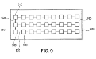
- Light source 800 is shown in FIG. 9 and includes a series of lighting elements 910, e.g., LED devices, coupled together with power leads 920, with the lighting elements 910 mounted on an inner reflective surface 930 of light source 800.
- the desired halo effect 120 is produced.
- Different colors can be produced for the halo effect 120 by either using colored lighting elements 910 or by using white light lighting elements 910 and adding a color filter layer to lens 200.
- lens 200 may alternatively be formed entirely from a plastic material tinted in the desired color.
- a variable color display, for the halo effect 120 may be provided by adding additional lighting elements in alternative colors to light source 800, with appropriate control circuitry or by using multicolor lighting elements instead of single colored lighting elements, and adding appropriate control circuitry.
Landscapes
- Engineering & Computer Science (AREA)
- Physics & Mathematics (AREA)
- General Physics & Mathematics (AREA)
- Theoretical Computer Science (AREA)
- General Engineering & Computer Science (AREA)
- Microelectronics & Electronic Packaging (AREA)
- Optics & Photonics (AREA)
- Accounting & Taxation (AREA)
- Marketing (AREA)
- Business, Economics & Management (AREA)
- Spectroscopy & Molecular Physics (AREA)
- Manufacturing & Machinery (AREA)
- Illuminated Signs And Luminous Advertising (AREA)
Abstract
Description
- This disclosure relates generally to a system and method for providing a decorative lighting display, and more particularly a system and method for providing a decorative lighting display that includes halo backlighting of three-dimensional figures such as letters and logos.
- Decorative lighting displays frequently achieve a "halo" lighting effect by use use of high voltage neon, incandescence or fluorescence type lighting devices mounted behind three-dimensional figures such as letters and logos which are spaced from a rear surface so that the back illumination from these conventional light sources causes this "halo" lighting effect. These light sources require that the three-dimensional figures be sufficiently large in area so that the light sources are hidden behind the rear of the each three-dimensional figure. This traditional approach cannot be used with smaller three-dimensional figures. In addition, neon lighting devices are expensive, fragile, generate excessive heat in operation and require a high voltage power source. Incandescent and florescent lighting devices have a limited lifetime and require specialized lenses to generate the "halo" lighting effect and to provide different colors of "halo" light.
- Accordingly, there is a need for a decorative lighting display which provides a "halo" lighting effect and overcomes the problems recited above.
- In a first aspect, a decorative lighting display system includes a panel having a recess formed in a front portion thereof. The panel also has an aperture formed in a portion of the recess from the front portion of the panel to a rear portion thereof. The system also includes a lens and an associated mask mounted in the recess in the panel. The associated mask is configured to have a predetermined pattern. The system also includes one or more three-dimensional figures mounted to the panel over the lens and associated mask. The one or more three-dimensional figures have a two-dimensional cross-section, in a plane parallel to the front portion of the panel, that is slightly smaller than the predetermined pattern of the associated mask. The system further includes a light source mounted on the rear portion of the panel over the aperture therein. The light source includes light elements for directing light through the lens and associated mask.
- In a further embodiment, the system may include a decorative laminate applied on the front portion of the panel to cover at least an area of the lens and associated mask. The decorative laminate may alternatively cover an area corresponding to an entire front portion of the panel. The one or more three-dimensional figures may be mounted flush against the panel over the lens and associated mask. The light elements in the light source may be LED devices. The LED devices may selectively emit different predetermined colors of light. The system may include a color filter having a predetermined color positioned adjacent to the lens. The lens may be formed from a plastic material which is tinted to a predetermined color. The lens may include mounting holes formed therein. The one or more three-dimensional figures may be mounted to the panel using the mounting holes in the lens.
- In a second aspect, a method for forming a decorative lighting display is disclosed. A recess is formed in a front portion of a panel. An aperture is formed in a portion of the recess in the panel from the front portion of the panel to a rear portion thereof. A lens and an associated mask are mounted in the recess in the panel. The associated mask configured to have a predetermined pattern. One or more three-dimensional figures are mounted to the panel over the lens and associated mask. The one or more three-dimensional figures have a two-dimensional cross-section, in a plane parallel to the front portion of the panel, which is slightly smaller than the predetermined pattern of the associated mask. Finally, a light source is mounted on the rear portion of the panel over the aperture therein. In a further embodiment, a decorative laminate may be applied on the front portion of the panel to cover at least an area of the lens and associated mask. In another further embodiment, each of the one or more three-dimensional figures is mounted flush against the panel.
- In a third aspect, a decorative lighting display system includes a panel having a recess formed in a front portion thereof. The panel has an aperture formed in a portion of the recess from the front portion of the panel to a rear portion thereof. The system also includes a lens mounted in the recess in the panel. The lens includes a mask formed thereon. The mask is configured to have a predetermined pattern. The system also includes one or more three-dimensional figures mounted to the panel over the lens and associated mask. The one or more three-dimensional figures have a two-dimensional cross-section, in a plane parallel to the front portion of the panel, which is slightly smaller than the predetermined pattern of the mask. The system further includes a light source mounted on the rear portion of the panel over the aperture therein. The light source includes light elements for directing light through the lens and associated mask.
- The features, functions, and advantages that have been discussed can be achieved independently in various embodiments or may be combined in yet other embodiments, further details of which can be seen with reference to the following description and drawings.
- The following detailed description, given by way of example and not intended to limit the present disclosure solely thereto, will best be understood in conjunction with the accompanying drawings in which:
-
FIG. 1 is front view of a panel having three-dimensional figures mounted thereto which shows the halo backlighting effect generated according to the system and method of the present disclosure; -
FIG. 2 is a front view of a lens assembly used in the system and method of the present disclosure; -
FIG. 3 is a front view of a masking layer used the system and method of the present disclosure; -
FIG. 4 is a front view showing a recess and through cutout in a panel for mounting three-dimensional figures according to an aspect of the system and method of the present disclosure; -
FIG. 5 is a front view showing a lens assembly and masking layer mounted in a through cutout in a panel for mounting three-dimensional figures according to an aspect of the system and method of the present disclosure; -
FIG. 6 is a cross-sectional view of the panel shown inFIG. 5 after thae decorative laminate is applied over a front surface thereof according to an aspect of the system and method of the present disclosure; -
FIG. 7 is a rear perspective view of the panel shown inFIG. 5 showing a cut-out area behind the lens assembly and masking layer according to an aspect of the system and method of the present disclosure; -
FIG. 8 a rear perspective view of the panel shown inFIG. 5 after a light box has been mounted thereto according to an aspect of the system and method of the present disclosure; and -
FIG. 9 is a front view of a light box according to an aspect of the system and method of the present disclosure. - In the present disclosure, like reference numbers refer to like elements throughout the drawings, which illustrate various exemplary embodiments of the present disclosure.
- Referring now to
FIG. 1 , apanel 100 includes a plurality of three-dimensional figures including three-dimensional letters 110 that spell out "BOEING" and the associated three-dimensional symbol 130 (together forming the well-known Boeing logo) which are mounted topanel 100 as discussed below.Panel 100 is configured, in a manner discussed below, to create ahalo lighting effect 120 around eachletter 110 andsymbol 130 without mounting a lighting assembly betweenpanel 100 and eachletter 110 andsymbol 130 as in conventional lighting displays. The system and method of the present disclosure are used inFIG. 1 to create a halo lighting effect around the Boeing logo, however, as one of ordinary skill in the art will readily recognize, this system and method can be applied to any type of three-dimensional figure including one or more letters, numbers and/or symbols. A halo lighting effect is created around three-dimensional figures mounted to a panel as discussed in detail below. - Referring now to
FIG. 2 , alens 200 is preferably constructed from a clear, rigid plastic material which may includeholes 210 pre-drilled therein for mounting the selected three-dimensional figures (here the Boeing logo). As one of ordinary skill in the art will readily recognize, other types of materials may also be used to constructlens 200. A masking layer (mask) 300 shown inFIG. 3 has the same outer dimensions aslens 200 and is formed from an opaque material (e.g., a thin aluminum sheet) which is affixed to theplastic lens 200 shown inFIG. 2 . Themasking layer 300 is constructed such that light is allowed to pass through only in select areas 310 (in this case the mask allows light to pass only through an area slightly larger than the outer dimensions of the selected three-dimensional figures). Maskinglayer 300 may be affixed tolens 200 with an adhesive or with mechanical fasteners, or may be, in the alternative, press-fit againstlens 200 during assembly, as discussed below. In an alternative embodiment, maskinglayer 300 may be formed directly onlens 200 using, for example, black paint. - Referring now to
FIG. 4 ,panel 100 is preferably formed from any rigid material which can be routed and cut. In a presently preferred embodiment for use on airlines,panel 100 is formed from a honeycomb material having an internal foam area. However, as one of ordinary skill in the art will readily recognize, almost any type of rigid material may be used.Panel 100 is preferably machined or routed to produce ashallow recess 410 designed to hold thelens 200 andmasking layer 300, although, as one of ordinary skill in the art will readily recognize, therecess 410 may be formed in many other ways.Panel 100 also includes a through cutout 400 (i.e., an aperture) in a portion ofrecess 410 that allows light from a light box mounted on the rear ofpanel 100, as discussed below, to reach thelens 200 andmasking layer 300. - Referring now to
FIGS. 5 and6 ,lens 200 and associatedmasking layer 300 may be bonded with an appropriate adhesive or fastened with fasteners into therecess 410 inpanel 100, although in some situations, thelens 200 andmasking layer 300 may be press-fit intorecess 410 and held securely without any adhesive or fasteners. Afterlens 200 andmasking layer 300 are installed, adecorative laminate 600 may be applied over the outer surface ofpanel 100.Decorative laminate 600 conceals thelens 200 from view and causespanel 100 to appear unmodified. As one of ordinary skill in the art will readily recognize, decorative laminate may cover the entire front surface ofpanel 100, may cover selected portions thereof (e.g., the front surface of lens 200) or, in some cases, may be omitted. The decorative laminate may be, for example, a wall-covering product (e.g., wallpaper) which allows at least some light to pass through. In a further embodiment, fairing compound may be applied to the seam betweenlens 200 andpanel 100 and then sanded to create a flat and level surface onto whichdecorative laminate 600 is applied. After the application of the decorative laminate 600 (if not omitted), the selected three-dimensional figures 110, 130 (shown inFIG. 1 ) are then be installed onto the front ofpanel 100, preferably using mounting holes 210 (FIG. 2 ) inlens 200. - Referring now to
FIG. 7 , a rear view ofpanel 100 is shown after installation oflens 200 andmasking layer 300 therein, withlens 200 andmasking layer 300 visible through thecutout 400. As shown inFIG. 8 , alight source 800, such as a light box, is preferably then affixed to the back of thepanel 100 over the cutout 400 (seen inFIG. 7 but covered bylight source 800 inFIG. 8 ). Light fromlight source 800 passes through thelens 200, illuminating thedecorative laminate 600 around the three-dimensional figures thereby creating the desiredhalo effect 120 around each of the three-dimensional figures 110, 130 as shown inFIG. 1 . The desired halo effect is thus produced in a different way than conventional systems and without using expensive neon light fixtures. In addition, the system and method of the present disclosure may be applied to three-dimensional figures much smaller than may be used in conventional systems that are limited by the size of the neon (or incandescent or florescent) lighting devices. Further, the system and method of the present disclosure can provide a smaller and more compact decorative lighting display, because the three-dimensional figures 110, 130 may be applied very close and even flush against the mountingpanel 100 as shown inFIG. 1 . This provides a distinct advantage over conventional lighting systems which, as discussed above in the Background, require lighting elements positioned between a three-dimensional figure and a mounting panel. -
Light source 800 is shown inFIG. 9 and includes a series oflighting elements 910, e.g., LED devices, coupled together with power leads 920, with thelighting elements 910 mounted on an innerreflective surface 930 oflight source 800. In operation, as shown inFIG. 1 , whenlight source 800 is activated, the desiredhalo effect 120 is produced. Different colors can be produced for thehalo effect 120 by either usingcolored lighting elements 910 or by using whitelight lighting elements 910 and adding a color filter layer tolens 200. As one of ordinary skill in the art will readily recognize,lens 200 may alternatively be formed entirely from a plastic material tinted in the desired color. Still further, a variable color display, for thehalo effect 120, may be provided by adding additional lighting elements in alternative colors tolight source 800, with appropriate control circuitry or by using multicolor lighting elements instead of single colored lighting elements, and adding appropriate control circuitry. - Further, the disclosure comprises embodiments according to the following clauses:
- Clause 1. A decorative lighting display system, comprising: a panel having a recess formed in a front portion thereof, the panel having an aperture formed in a portion of the recess from the front portion of the panel to a rear portion thereof; a lens and an associated mask mounted in the recess in the panel, the associated mask configured to have a predetermined pattern; one or more three-dimensional figures mounted to the panel over the lens and associated mask, the one or more three-dimensional figures having a two-dimensional cross-section, in a plane parallel to the front portion of the panel, that is slightly smaller than the predetermined pattern of the associated mask; and a light source mounted on the rear portion of the panel over the aperture therein, the light source including light elements for directing light through the lens and associated mask.
- Clause 2. The decorative lighting display system of Clause 1, further comprising a decorative laminate applied on the front portion of the panel to cover at least an area of the lens and associated mask.
- Clause 3. The decorative lighting display system of Clause 2, wherein the decorative laminate covers an area corresponding to an entire front portion of the panel.
- Clause 4. The decorative lighting display system of one of Clauses 1 to 3, wherein the one or more three-dimensional figures are mounted flush against the panel over the lens and associated mask.
- Clause 5. The decorative lighting display system of one of Clauses 1 to 4, wherein the light elements in the light source are LED devices.
- Clause 6. The decorative lighting display system of Clause 5, wherein the LED devices selectively emit different predetermined colors of light.
- Clause 7. The decorative lighting display system of one of Clauses 1 to 6, further comprising a color filter having a predetermined color positioned adjacent to the lens.
- Clause 8. The decorative lighting display system of one of Clauses 1 to 7, wherein the lens is formed from a plastic material which is tinted to a predetermined color.
- Clause 9. The decorative lighting display system of one of Clauses 1 to 8, wherein the lens includes mounting holes formed therein and wherein the one or more three-dimensional figures are mounted to the panel using the mounting holes in the lens.
- Clause 10. A method for forming a decorative lighting display, comprising the steps of: forming a recess in a front portion of a panel; forming an aperture in a portion of the recess in the panel from the front portion of the panel to a rear portion thereof; mounting a lens and an associated mask in the recess in the panel, the associated mask configured to have a predetermined pattern; mounting one or more three-dimensional figures to the panel over the lens and associated mask, the one or more three-dimensional figures having a two-dimensional cross-section, in a plane parallel to the front portion of the panel, that is slightly smaller than the predetermined pattern of the associated mask; and mounting a light source on the rear portion of the panel over the aperture therein.
- Clause 11. The method for forming a decorative lighting display of Clause 10, further comprising the step of, prior to the step of mounting one or more three-dimensional figures to the panel, applying a decorative laminate on the front portion of the panel to cover at least an area of the lens and associated mask.
- Clause 12. The method for forming a decorative lighting display of Clause 10 or 11, wherein the step of mounting one or more three-dimensional figures to the panel over the lens and associated mask mounts each of the one or more three-dimensional figures flush against the panel.
-
Clause 13. A decorative lighting display system, comprising: a panel having a recess formed in a front portion thereof, the panel having an aperture formed in a portion of the recess from the front portion of the panel to a rear portion thereof; a lens mounted in the recess in the panel, the lens including a mask formed thereon, the mask configured to have a predetermined pattern; one or more three-dimensional figures mounted to the panel over the lens and mask, the one or more three-dimensional figures having a two-dimensional cross-section, in a plane parallel to the front portion of the panel, that is slightly smaller than the predetermined pattern of the mask; and a light source mounted on the rear portion of the panel over the aperture therein, the light source including light elements for directing light through the lens and mask. - Clause 14. The decorative light display system of
Clause 13, further comprising a decorative laminate applied on the front portion of the panel to cover at least an area of the lens. - Clause 15. The decorative lighting display system of Clause 14, wherein the decorative laminate covers an area corresponding to an entire front portion of the panel.
- Clause 16. The decorative lighting display system of one of
Clauses 13 to 15, wherein the one or more three-dimensional figures are mounted flush against the panel over the lens and associated mask. - Clause 17. The decorative lighting display system of one of
Clauses 13 to 16, wherein the light elements in the light source are LED devices which selectively emit different predetermined colors of light. - Clause 18. The decorative lighting display system of one of
Clauses 13 to 17, further comprising a color filter having a predetermined color positioned adjacent to the lens. - Clause 19. The decorative lighting display system of one of
Clauses 13 to 18, wherein the lens is formed from a plastic material which is tinted to a predetermined color. - Clause 20. The decorative lighting display system of one of
Clauses 13 to 19, wherein the lens includes mounting holes formed therein and wherein the one or more three-dimensional figures are mounted to the panel using the mounting holes in the lens. - Although the present disclosure has been particularly shown and described with reference to the preferred embodiments and various aspects thereof, it will be appreciated by those of ordinary skill in the art that various changes and modifications may be made without departing from the spirit and scope of the disclosure. It is intended that the appended claims be interpreted as including the embodiments described herein, the alternatives mentioned above, and all equivalents thereto.
Claims (13)
- A decorative lighting display system, comprising:a panel (100) having a recess (410) formed in a front portion thereof, the panel having an aperture (400) formed in a portion of the recess from the front portion of the panel to a rear portion thereof;a lens (200) and an associated mask (300) mounted in the recess in the panel, the associated mask configured to have a predetermined pattern;one or more three-dimensional figures (110, 130) mounted to the panel over the lens and associated mask, the one or more three-dimensional figures having a two-dimensional cross-section, in a plane parallel to the front portion of the panel, that is slightly smaller than the predetermined pattern of the associated mask; anda light source (800) mounted on the rear portion of the panel over the aperture therein, the light source including lighting elements (910) for directing light through the lens and associated mask.
- The decorative lighting display system of claim 1, wherein the lens (200) includes the mask (300) formed thereon.
- The decorative lighting display system of claim 1 or 2, further comprising a decorative laminate (600) applied on the front portion of the panel (100) to cover at least an area of the lens (200) and associated mask (300).
- The decorative lighting display system of claim 3, wherein the decorative laminate (600) covers an area corresponding to an entire front portion of the panel (100).
- The decorative lighting display system of any preceding claim, wherein the one or more three-dimensional figures (110, 130) are mounted flush against the panel (100) over the lens (200) and associated mask (300).
- The decorative lighting display system of any preceding claim, wherein the lighting elements (910) in the light source (800) are LED devices.
- The decorative lighting display system of claim 6, wherein the LED devices selectively emit different predetermined colors of light.
- The decorative lighting display system of any preceding claim, further comprising a color filter having a predetermined color positioned adjacent to the lens (200).
- The decorative lighting display system of any preceding claim, wherein the lens (200) is formed from a plastic material which is tinted to a predetermined color.
- The decorative lighting display system of any preceding claim, wherein the lens (200) includes mounting holes (210) formed therein, and wherein the one or more three-dimensional figures (110, 130) are mounted to the panel (100) using the mounting holes in the lens.
- A method for forming a decorative lighting display, comprising the steps of:forming a recess (410) in a front portion of a panel (100);forming an aperture (400) in a portion of the recess in the panel from the front portion of the panel to a rear portion thereof;mounting a lens (200) and an associated mask (300) in the recess in the panel, the associated mask configured to have a predetermined pattern;mounting one or more three-dimensional figures (110, 130) to the panel over the lens and associated mask, the one or more three-dimensional figures having a two-dimensional cross-section, in a plane parallel to the front portion of the panel, that is slightly smaller than the predetermined pattern of the associated mask; andmounting a light source (800) on the rear portion of the panel over the aperture therein.
- The method for forming a decorative lighting display of claim 11, further comprising the step of, prior to the step of mounting one or more three-dimensional figures (110, 130) to the panel (100), applying a decorative laminate (600) on the front portion of the panel to cover at least an area of the lens (200) and associated mask (300).
- The method for forming a decorative lighting display of claim 11 or 12, wherein the step of mounting one or more three-dimensional figures (110, 130) to the panel (100) over the lens (200) and associated mask (300) mounts each of the one or more three-dimensional figures flush against the panel.
Applications Claiming Priority (1)
| Application Number | Priority Date | Filing Date | Title |
|---|---|---|---|
| US14/694,475 US10062308B2 (en) | 2015-04-23 | 2015-04-23 | System and method for providing a decorative lighting display |
Publications (2)
| Publication Number | Publication Date |
|---|---|
| EP3086307A1 true EP3086307A1 (en) | 2016-10-26 |
| EP3086307B1 EP3086307B1 (en) | 2018-08-29 |
Family
ID=55521412
Family Applications (1)
| Application Number | Title | Priority Date | Filing Date |
|---|---|---|---|
| EP16155972.9A Not-in-force EP3086307B1 (en) | 2015-04-23 | 2016-02-16 | System and method for providing a decorative lighting display |
Country Status (4)
| Country | Link |
|---|---|
| US (1) | US10062308B2 (en) |
| EP (1) | EP3086307B1 (en) |
| JP (1) | JP6758050B2 (en) |
| CN (1) | CN106067284B (en) |
Cited By (1)
| Publication number | Priority date | Publication date | Assignee | Title |
|---|---|---|---|---|
| EP3438957A1 (en) * | 2017-08-04 | 2019-02-06 | Depo Auto Parts Ind. Co., Ltd. | Graphic luminous device |
Families Citing this family (2)
| Publication number | Priority date | Publication date | Assignee | Title |
|---|---|---|---|---|
| US11105969B2 (en) * | 2018-02-09 | 2021-08-31 | Panasonic Intellectual Property Management Co., Ltd. | Display device and input device |
| EP4074551B1 (en) * | 2021-04-16 | 2026-02-18 | OPmobility SE | Automotive bodywork part comprising an ornamental motif |
Citations (4)
| Publication number | Priority date | Publication date | Assignee | Title |
|---|---|---|---|---|
| WO1999049441A1 (en) * | 1998-03-26 | 1999-09-30 | Chisholm, James, H. | Sign for illumination utilizing translucent layers |
| US20100154261A1 (en) * | 2008-11-26 | 2010-06-24 | Johnson Controls Technology Company | Illuminated trim panels |
| US20110052839A1 (en) * | 2009-09-03 | 2011-03-03 | Joel Thomas Pierce | Showcase display badge |
| EP2309477A1 (en) * | 2009-10-09 | 2011-04-13 | Braun GmbH | Display panel |
Family Cites Families (24)
| Publication number | Priority date | Publication date | Assignee | Title |
|---|---|---|---|---|
| US2810225A (en) * | 1956-07-26 | 1957-10-22 | George K C Hardesty | Illuminated panel-modifications of duo-panel system |
| JPS58192688U (en) * | 1982-06-17 | 1983-12-21 | ダイキン工業株式会社 | Nameplate structure in equipment |
| JPS6438894U (en) * | 1987-09-02 | 1989-03-08 | ||
| US5232388A (en) | 1992-10-08 | 1993-08-03 | Barbara Danjell | "Glow" signage and method for manufacturing same |
| JP2590647Y2 (en) * | 1993-03-12 | 1999-02-17 | 市光工業株式会社 | Display device |
| US6113149A (en) * | 1997-12-19 | 2000-09-05 | Serigraph, Inc. | Pseudo three-dimensional image display and method of manufacturing including tactile surface texture |
| US6092915A (en) | 1998-01-30 | 2000-07-25 | The Boeing Company | Decorative lighting laminate |
| US6024476A (en) | 1998-04-21 | 2000-02-15 | Us Sign And Fabrication Corporation | Optical fiber lighting of channel letters |
| US6726350B1 (en) | 2002-05-29 | 2004-04-27 | Michael A. Herold | Simulated neon-light tube |
| CA2411422A1 (en) | 2002-11-08 | 2004-05-08 | Hossein Arvin | Illuminated indicia |
| US7162821B2 (en) * | 2003-06-20 | 2007-01-16 | Identity Group, Inc. | Illuminated sign |
| JP2005053025A (en) * | 2003-08-01 | 2005-03-03 | Masao Yoshida | Displaying panel with inner drawing image of multi-dimensional decoration |
| US20050213351A1 (en) * | 2004-03-23 | 2005-09-29 | Chang-An Yang | Light-Guiding structure for floor-pan edge of a car |
| JP2005275018A (en) * | 2004-03-25 | 2005-10-06 | Tanikawa Shoji Kk | Display device |
| JP2006017845A (en) * | 2004-06-30 | 2006-01-19 | Masayuki Kawasaki | Display device, toy and video display method |
| GB2416063A (en) | 2004-07-08 | 2006-01-11 | Kristjan Arnthorsson | Layered graphic display panel |
| JP2007256385A (en) * | 2006-03-20 | 2007-10-04 | Sharp Corp | Optical sheet unit |
| US7467486B2 (en) | 2006-05-22 | 2008-12-23 | Kaoh Andy K F | Method and apparatus for simulating the appearance of a neon sign |
| US8033684B2 (en) | 2007-08-31 | 2011-10-11 | The Boeing Company | Starry sky lighting panels |
| US7857484B2 (en) | 2007-08-31 | 2010-12-28 | The Boeing Company | Lighting panels including embedded illumination devices and methods of making such panels |
| US8979290B2 (en) * | 2008-04-15 | 2015-03-17 | Paul E. Lohneis | Three-dimensional lighting structure utilizing light active technology |
| US8418385B2 (en) | 2010-09-06 | 2013-04-16 | Michael Roger Olson | Lighting device |
| JP2012155143A (en) * | 2011-01-26 | 2012-08-16 | Sunarrow Ltd | Display board, display device, electronic apparatus, and measurement device |
| KR101279402B1 (en) * | 2011-10-21 | 2013-06-27 | (주)코텍 | Advertising display device having 3d sheet |
-
2015
- 2015-04-23 US US14/694,475 patent/US10062308B2/en not_active Expired - Fee Related
-
2016
- 2016-02-10 JP JP2016023429A patent/JP6758050B2/en not_active Expired - Fee Related
- 2016-02-16 EP EP16155972.9A patent/EP3086307B1/en not_active Not-in-force
- 2016-03-10 CN CN201610136607.1A patent/CN106067284B/en not_active Expired - Fee Related
Patent Citations (4)
| Publication number | Priority date | Publication date | Assignee | Title |
|---|---|---|---|---|
| WO1999049441A1 (en) * | 1998-03-26 | 1999-09-30 | Chisholm, James, H. | Sign for illumination utilizing translucent layers |
| US20100154261A1 (en) * | 2008-11-26 | 2010-06-24 | Johnson Controls Technology Company | Illuminated trim panels |
| US20110052839A1 (en) * | 2009-09-03 | 2011-03-03 | Joel Thomas Pierce | Showcase display badge |
| EP2309477A1 (en) * | 2009-10-09 | 2011-04-13 | Braun GmbH | Display panel |
Cited By (1)
| Publication number | Priority date | Publication date | Assignee | Title |
|---|---|---|---|---|
| EP3438957A1 (en) * | 2017-08-04 | 2019-02-06 | Depo Auto Parts Ind. Co., Ltd. | Graphic luminous device |
Also Published As
| Publication number | Publication date |
|---|---|
| US20160314726A1 (en) | 2016-10-27 |
| US10062308B2 (en) | 2018-08-28 |
| CN106067284A (en) | 2016-11-02 |
| JP2016206649A (en) | 2016-12-08 |
| CN106067284B (en) | 2020-01-10 |
| JP6758050B2 (en) | 2020-09-23 |
| EP3086307B1 (en) | 2018-08-29 |
Similar Documents
| Publication | Publication Date | Title |
|---|---|---|
| US10449894B2 (en) | Display device for displaying at least one symbol, switching device, and method for manufacturing a display device | |
| CN107757515B (en) | Illuminated emblem for a vehicle | |
| US9449539B2 (en) | Simulated neon sign | |
| US20190210520A1 (en) | Illumination systems for a steering assembly | |
| CA2934303A1 (en) | Stacked transparent lighting system for vehicle trim components | |
| JP6831789B2 (en) | balloon | |
| EP3086307B1 (en) | System and method for providing a decorative lighting display | |
| JP6785026B2 (en) | Photoluminescence cover for instruction signs | |
| US20070227055A1 (en) | Lighted sign | |
| KR101558421B1 (en) | LED channel signboard | |
| CN116913182A (en) | Multifunctional glass and vehicles | |
| EP3184363B1 (en) | Lighting device for an interior panel of a vehicle | |
| EP3477185B1 (en) | Vehicular lamp and vehicle comprising same | |
| US20170349285A1 (en) | Lighting arrangement for an interior of a vehicle | |
| US11420746B2 (en) | Interior panel for an interior of an aircraft and a method for making the same | |
| JP2009012558A (en) | Decorative structure | |
| US9175833B2 (en) | Graphics display module | |
| KR20160107870A (en) | Channel for light emission of multi-side for advertising | |
| KR101000452B1 (en) | Lighting device using light guide plate | |
| US11837111B1 (en) | Illuminated sign assembly | |
| GB2474894A (en) | An illuminated vehicle registration plate with a halo effect | |
| CN222988094U (en) | Optical ornament for vehicle and vehicle | |
| US20200320912A1 (en) | Lighted image display assembly | |
| JP2005025004A (en) | Display board | |
| KR101823436B1 (en) | LED Tinting paper |
Legal Events
| Date | Code | Title | Description |
|---|---|---|---|
| PUAI | Public reference made under article 153(3) epc to a published international application that has entered the european phase |
Free format text: ORIGINAL CODE: 0009012 |
|
| 17P | Request for examination filed |
Effective date: 20160216 |
|
| AK | Designated contracting states |
Kind code of ref document: A1 Designated state(s): AL AT BE BG CH CY CZ DE DK EE ES FI FR GB GR HR HU IE IS IT LI LT LU LV MC MK MT NL NO PL PT RO RS SE SI SK SM TR |
|
| AX | Request for extension of the european patent |
Extension state: BA ME |
|
| RBV | Designated contracting states (corrected) |
Designated state(s): AL AT BE BG CH CY CZ DE DK EE ES FI FR GB GR HR HU IE IS IT LI LT LU LV MC MK MT NL NO PL PT RO RS SE SI SK SM TR |
|
| GRAP | Despatch of communication of intention to grant a patent |
Free format text: ORIGINAL CODE: EPIDOSNIGR1 |
|
| STAA | Information on the status of an ep patent application or granted ep patent |
Free format text: STATUS: GRANT OF PATENT IS INTENDED |
|
| INTG | Intention to grant announced |
Effective date: 20180126 |
|
| GRAJ | Information related to disapproval of communication of intention to grant by the applicant or resumption of examination proceedings by the epo deleted |
Free format text: ORIGINAL CODE: EPIDOSDIGR1 |
|
| STAA | Information on the status of an ep patent application or granted ep patent |
Free format text: STATUS: REQUEST FOR EXAMINATION WAS MADE |
|
| GRAP | Despatch of communication of intention to grant a patent |
Free format text: ORIGINAL CODE: EPIDOSNIGR1 |
|
| STAA | Information on the status of an ep patent application or granted ep patent |
Free format text: STATUS: GRANT OF PATENT IS INTENDED |
|
| INTC | Intention to grant announced (deleted) | ||
| INTG | Intention to grant announced |
Effective date: 20180326 |
|
| GRAS | Grant fee paid |
Free format text: ORIGINAL CODE: EPIDOSNIGR3 |
|
| GRAA | (expected) grant |
Free format text: ORIGINAL CODE: 0009210 |
|
| STAA | Information on the status of an ep patent application or granted ep patent |
Free format text: STATUS: THE PATENT HAS BEEN GRANTED |
|
| AK | Designated contracting states |
Kind code of ref document: B1 Designated state(s): AL AT BE BG CH CY CZ DE DK EE ES FI FR GB GR HR HU IE IS IT LI LT LU LV MC MK MT NL NO PL PT RO RS SE SI SK SM TR |
|
| REG | Reference to a national code |
Ref country code: GB Ref legal event code: FG4D |
|
| REG | Reference to a national code |
Ref country code: CH Ref legal event code: EP |
|
| REG | Reference to a national code |
Ref country code: AT Ref legal event code: REF Ref document number: 1036080 Country of ref document: AT Kind code of ref document: T Effective date: 20180915 |
|
| REG | Reference to a national code |
Ref country code: IE Ref legal event code: FG4D |
|
| REG | Reference to a national code |
Ref country code: DE Ref legal event code: R096 Ref document number: 602016005049 Country of ref document: DE |
|
| REG | Reference to a national code |
Ref country code: NL Ref legal event code: MP Effective date: 20180829 |
|
| REG | Reference to a national code |
Ref country code: LT Ref legal event code: MG4D |
|
| PG25 | Lapsed in a contracting state [announced via postgrant information from national office to epo] |
Ref country code: GR Free format text: LAPSE BECAUSE OF FAILURE TO SUBMIT A TRANSLATION OF THE DESCRIPTION OR TO PAY THE FEE WITHIN THE PRESCRIBED TIME-LIMIT Effective date: 20181130 Ref country code: IS Free format text: LAPSE BECAUSE OF FAILURE TO SUBMIT A TRANSLATION OF THE DESCRIPTION OR TO PAY THE FEE WITHIN THE PRESCRIBED TIME-LIMIT Effective date: 20181229 Ref country code: NL Free format text: LAPSE BECAUSE OF FAILURE TO SUBMIT A TRANSLATION OF THE DESCRIPTION OR TO PAY THE FEE WITHIN THE PRESCRIBED TIME-LIMIT Effective date: 20180829 Ref country code: LT Free format text: LAPSE BECAUSE OF FAILURE TO SUBMIT A TRANSLATION OF THE DESCRIPTION OR TO PAY THE FEE WITHIN THE PRESCRIBED TIME-LIMIT Effective date: 20180829 Ref country code: BG Free format text: LAPSE BECAUSE OF FAILURE TO SUBMIT A TRANSLATION OF THE DESCRIPTION OR TO PAY THE FEE WITHIN THE PRESCRIBED TIME-LIMIT Effective date: 20181129 Ref country code: NO Free format text: LAPSE BECAUSE OF FAILURE TO SUBMIT A TRANSLATION OF THE DESCRIPTION OR TO PAY THE FEE WITHIN THE PRESCRIBED TIME-LIMIT Effective date: 20181129 Ref country code: SE Free format text: LAPSE BECAUSE OF FAILURE TO SUBMIT A TRANSLATION OF THE DESCRIPTION OR TO PAY THE FEE WITHIN THE PRESCRIBED TIME-LIMIT Effective date: 20180829 Ref country code: RS Free format text: LAPSE BECAUSE OF FAILURE TO SUBMIT A TRANSLATION OF THE DESCRIPTION OR TO PAY THE FEE WITHIN THE PRESCRIBED TIME-LIMIT Effective date: 20180829 Ref country code: FI Free format text: LAPSE BECAUSE OF FAILURE TO SUBMIT A TRANSLATION OF THE DESCRIPTION OR TO PAY THE FEE WITHIN THE PRESCRIBED TIME-LIMIT Effective date: 20180829 |
|
| REG | Reference to a national code |
Ref country code: AT Ref legal event code: MK05 Ref document number: 1036080 Country of ref document: AT Kind code of ref document: T Effective date: 20180829 |
|
| PG25 | Lapsed in a contracting state [announced via postgrant information from national office to epo] |
Ref country code: AL Free format text: LAPSE BECAUSE OF FAILURE TO SUBMIT A TRANSLATION OF THE DESCRIPTION OR TO PAY THE FEE WITHIN THE PRESCRIBED TIME-LIMIT Effective date: 20180829 Ref country code: LV Free format text: LAPSE BECAUSE OF FAILURE TO SUBMIT A TRANSLATION OF THE DESCRIPTION OR TO PAY THE FEE WITHIN THE PRESCRIBED TIME-LIMIT Effective date: 20180829 Ref country code: HR Free format text: LAPSE BECAUSE OF FAILURE TO SUBMIT A TRANSLATION OF THE DESCRIPTION OR TO PAY THE FEE WITHIN THE PRESCRIBED TIME-LIMIT Effective date: 20180829 |
|
| PG25 | Lapsed in a contracting state [announced via postgrant information from national office to epo] |
Ref country code: IT Free format text: LAPSE BECAUSE OF FAILURE TO SUBMIT A TRANSLATION OF THE DESCRIPTION OR TO PAY THE FEE WITHIN THE PRESCRIBED TIME-LIMIT Effective date: 20180829 Ref country code: PL Free format text: LAPSE BECAUSE OF FAILURE TO SUBMIT A TRANSLATION OF THE DESCRIPTION OR TO PAY THE FEE WITHIN THE PRESCRIBED TIME-LIMIT Effective date: 20180829 Ref country code: AT Free format text: LAPSE BECAUSE OF FAILURE TO SUBMIT A TRANSLATION OF THE DESCRIPTION OR TO PAY THE FEE WITHIN THE PRESCRIBED TIME-LIMIT Effective date: 20180829 Ref country code: EE Free format text: LAPSE BECAUSE OF FAILURE TO SUBMIT A TRANSLATION OF THE DESCRIPTION OR TO PAY THE FEE WITHIN THE PRESCRIBED TIME-LIMIT Effective date: 20180829 Ref country code: RO Free format text: LAPSE BECAUSE OF FAILURE TO SUBMIT A TRANSLATION OF THE DESCRIPTION OR TO PAY THE FEE WITHIN THE PRESCRIBED TIME-LIMIT Effective date: 20180829 Ref country code: ES Free format text: LAPSE BECAUSE OF FAILURE TO SUBMIT A TRANSLATION OF THE DESCRIPTION OR TO PAY THE FEE WITHIN THE PRESCRIBED TIME-LIMIT Effective date: 20180829 Ref country code: CZ Free format text: LAPSE BECAUSE OF FAILURE TO SUBMIT A TRANSLATION OF THE DESCRIPTION OR TO PAY THE FEE WITHIN THE PRESCRIBED TIME-LIMIT Effective date: 20180829 |
|
| PG25 | Lapsed in a contracting state [announced via postgrant information from national office to epo] |
Ref country code: SK Free format text: LAPSE BECAUSE OF FAILURE TO SUBMIT A TRANSLATION OF THE DESCRIPTION OR TO PAY THE FEE WITHIN THE PRESCRIBED TIME-LIMIT Effective date: 20180829 Ref country code: SM Free format text: LAPSE BECAUSE OF FAILURE TO SUBMIT A TRANSLATION OF THE DESCRIPTION OR TO PAY THE FEE WITHIN THE PRESCRIBED TIME-LIMIT Effective date: 20180829 Ref country code: DK Free format text: LAPSE BECAUSE OF FAILURE TO SUBMIT A TRANSLATION OF THE DESCRIPTION OR TO PAY THE FEE WITHIN THE PRESCRIBED TIME-LIMIT Effective date: 20180829 |
|
| REG | Reference to a national code |
Ref country code: DE Ref legal event code: R097 Ref document number: 602016005049 Country of ref document: DE |
|
| PLBE | No opposition filed within time limit |
Free format text: ORIGINAL CODE: 0009261 |
|
| STAA | Information on the status of an ep patent application or granted ep patent |
Free format text: STATUS: NO OPPOSITION FILED WITHIN TIME LIMIT |
|
| 26N | No opposition filed |
Effective date: 20190531 |
|
| PG25 | Lapsed in a contracting state [announced via postgrant information from national office to epo] |
Ref country code: SI Free format text: LAPSE BECAUSE OF FAILURE TO SUBMIT A TRANSLATION OF THE DESCRIPTION OR TO PAY THE FEE WITHIN THE PRESCRIBED TIME-LIMIT Effective date: 20180829 |
|
| REG | Reference to a national code |
Ref country code: CH Ref legal event code: PL |
|
| PG25 | Lapsed in a contracting state [announced via postgrant information from national office to epo] |
Ref country code: LU Free format text: LAPSE BECAUSE OF NON-PAYMENT OF DUE FEES Effective date: 20190216 Ref country code: MC Free format text: LAPSE BECAUSE OF FAILURE TO SUBMIT A TRANSLATION OF THE DESCRIPTION OR TO PAY THE FEE WITHIN THE PRESCRIBED TIME-LIMIT Effective date: 20180829 |
|
| REG | Reference to a national code |
Ref country code: BE Ref legal event code: MM Effective date: 20190228 |
|
| REG | Reference to a national code |
Ref country code: IE Ref legal event code: MM4A |
|
| PG25 | Lapsed in a contracting state [announced via postgrant information from national office to epo] |
Ref country code: CH Free format text: LAPSE BECAUSE OF NON-PAYMENT OF DUE FEES Effective date: 20190228 Ref country code: LI Free format text: LAPSE BECAUSE OF NON-PAYMENT OF DUE FEES Effective date: 20190228 |
|
| PG25 | Lapsed in a contracting state [announced via postgrant information from national office to epo] |
Ref country code: IE Free format text: LAPSE BECAUSE OF NON-PAYMENT OF DUE FEES Effective date: 20190216 |
|
| PG25 | Lapsed in a contracting state [announced via postgrant information from national office to epo] |
Ref country code: BE Free format text: LAPSE BECAUSE OF NON-PAYMENT OF DUE FEES Effective date: 20190228 |
|
| PG25 | Lapsed in a contracting state [announced via postgrant information from national office to epo] |
Ref country code: TR Free format text: LAPSE BECAUSE OF FAILURE TO SUBMIT A TRANSLATION OF THE DESCRIPTION OR TO PAY THE FEE WITHIN THE PRESCRIBED TIME-LIMIT Effective date: 20180829 |
|
| PG25 | Lapsed in a contracting state [announced via postgrant information from national office to epo] |
Ref country code: MT Free format text: LAPSE BECAUSE OF NON-PAYMENT OF DUE FEES Effective date: 20190216 Ref country code: PT Free format text: LAPSE BECAUSE OF FAILURE TO SUBMIT A TRANSLATION OF THE DESCRIPTION OR TO PAY THE FEE WITHIN THE PRESCRIBED TIME-LIMIT Effective date: 20181229 |
|
| PGFP | Annual fee paid to national office [announced via postgrant information from national office to epo] |
Ref country code: FR Payment date: 20210223 Year of fee payment: 6 |
|
| PG25 | Lapsed in a contracting state [announced via postgrant information from national office to epo] |
Ref country code: CY Free format text: LAPSE BECAUSE OF FAILURE TO SUBMIT A TRANSLATION OF THE DESCRIPTION OR TO PAY THE FEE WITHIN THE PRESCRIBED TIME-LIMIT Effective date: 20180829 |
|
| PGFP | Annual fee paid to national office [announced via postgrant information from national office to epo] |
Ref country code: DE Payment date: 20210225 Year of fee payment: 6 Ref country code: GB Payment date: 20210225 Year of fee payment: 6 |
|
| PG25 | Lapsed in a contracting state [announced via postgrant information from national office to epo] |
Ref country code: HU Free format text: LAPSE BECAUSE OF FAILURE TO SUBMIT A TRANSLATION OF THE DESCRIPTION OR TO PAY THE FEE WITHIN THE PRESCRIBED TIME-LIMIT; INVALID AB INITIO Effective date: 20160216 |
|
| PG25 | Lapsed in a contracting state [announced via postgrant information from national office to epo] |
Ref country code: MK Free format text: LAPSE BECAUSE OF FAILURE TO SUBMIT A TRANSLATION OF THE DESCRIPTION OR TO PAY THE FEE WITHIN THE PRESCRIBED TIME-LIMIT Effective date: 20180829 |
|
| REG | Reference to a national code |
Ref country code: DE Ref legal event code: R119 Ref document number: 602016005049 Country of ref document: DE |
|
| GBPC | Gb: european patent ceased through non-payment of renewal fee |
Effective date: 20220216 |
|
| PG25 | Lapsed in a contracting state [announced via postgrant information from national office to epo] |
Ref country code: FR Free format text: LAPSE BECAUSE OF NON-PAYMENT OF DUE FEES Effective date: 20220228 |
|
| PG25 | Lapsed in a contracting state [announced via postgrant information from national office to epo] |
Ref country code: GB Free format text: LAPSE BECAUSE OF NON-PAYMENT OF DUE FEES Effective date: 20220216 Ref country code: DE Free format text: LAPSE BECAUSE OF NON-PAYMENT OF DUE FEES Effective date: 20220901 |