EP3086129A1 - Electric current detector - Google Patents
Electric current detector Download PDFInfo
- Publication number
- EP3086129A1 EP3086129A1 EP16166471.9A EP16166471A EP3086129A1 EP 3086129 A1 EP3086129 A1 EP 3086129A1 EP 16166471 A EP16166471 A EP 16166471A EP 3086129 A1 EP3086129 A1 EP 3086129A1
- Authority
- EP
- European Patent Office
- Prior art keywords
- electric current
- core
- current detector
- magnetic
- circuit board
- Prior art date
- Legal status (The legal status is an assumption and is not a legal conclusion. Google has not performed a legal analysis and makes no representation as to the accuracy of the status listed.)
- Granted
Links
Images


Classifications
-
- G—PHYSICS
- G01—MEASURING; TESTING
- G01R—MEASURING ELECTRIC VARIABLES; MEASURING MAGNETIC VARIABLES
- G01R15/00—Details of measuring arrangements of the types provided for in groups G01R17/00 - G01R29/00, G01R33/00 - G01R33/26 or G01R35/00
- G01R15/14—Adaptations providing voltage or current isolation, e.g. for high-voltage or high-current networks
- G01R15/18—Adaptations providing voltage or current isolation, e.g. for high-voltage or high-current networks using inductive devices, e.g. transformers
- G01R15/183—Adaptations providing voltage or current isolation, e.g. for high-voltage or high-current networks using inductive devices, e.g. transformers using transformers with a magnetic core
- G01R15/185—Adaptations providing voltage or current isolation, e.g. for high-voltage or high-current networks using inductive devices, e.g. transformers using transformers with a magnetic core with compensation or feedback windings or interacting coils, e.g. 0-flux sensors
-
- G—PHYSICS
- G01—MEASURING; TESTING
- G01R—MEASURING ELECTRIC VARIABLES; MEASURING MAGNETIC VARIABLES
- G01R19/00—Arrangements for measuring currents or voltages or for indicating presence or sign thereof
- G01R19/0092—Measuring current only
-
- G—PHYSICS
- G01—MEASURING; TESTING
- G01R—MEASURING ELECTRIC VARIABLES; MEASURING MAGNETIC VARIABLES
- G01R33/00—Arrangements or instruments for measuring magnetic variables
- G01R33/0011—Arrangements or instruments for measuring magnetic variables comprising means, e.g. flux concentrators, flux guides, for guiding or concentrating the magnetic flux, e.g. to the magnetic sensor
-
- H—ELECTRICITY
- H01—ELECTRIC ELEMENTS
- H01F—MAGNETS; INDUCTANCES; TRANSFORMERS; SELECTION OF MATERIALS FOR THEIR MAGNETIC PROPERTIES
- H01F3/00—Cores, Yokes, or armatures
- H01F3/10—Composite arrangements of magnetic circuits
- H01F3/14—Constrictions; Gaps, e.g. air-gaps
Definitions
- the present invention contains subject matters related to Japanese Patent Applications JP2015-089092 and JP2016-034974 filed in the Japanese Patent Office on April 24, 2015 and on February 26, 2016 respectively, the entire contents of which being incorporated herein by reference.
- the present invention relates to an electric current detector.
- a certain electric current sensor based on a magnetic balance system includes a vertical-type (that is, vertically placed) annular core, a primary conductor is arranged so as to interlink with that annular core, and a compensating coil (secondary coil) is installed on the annular core. Further, a cavity is provided at the bottom portion of the annular core and a stick-shaped fluxgate-type sensor is inserted into that cavity.
- a control circuit board for driving that sensor is provided separately from the circuit board on which this electric current sensor is mounted and is connected to that sensor (for example, see Patent Document 1: Japanese unexamined PCT publication No. 2011-510318 ).
- the above-mentioned electric current sensor uses a vertical-type annular core and therefore, is configured to have a high profile, in which in the case of installing this electric current sensor on a circuit board, a space is required on the upper side of the circuit board in conformity with the height of this electric current sensor.
- the present invention was invented in view of the aforesaid problem and is addressed to obtain a low-profile electric current detector.
- the electric current detector relating to the present invention is an electric current detector which is mountable on a circuit board on which there is mounted a fluxgate-type magnetic sensor IC chip which detects magnetic flux for electric current detection, in which there is included a substantially ring-shaped core which forms a magnetic-path for magnetic flux induced by detection-target electric current. Then, the core includes a gap which is arranged to become substantially parallel with respect to the circuit board when mounting the aforesaid electric current detector on the circuit board and which is at a place positioned on or on the upper side of the magnetic sensor IC chip in the magnetic-path when mounting the aforesaid electric current detector on the circuit board.
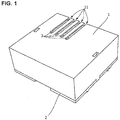
- FIG. 1 is a perspective view showing an electric current detector relating to an example 1 of the present invention.
- FIG. 2 is a perspective view showing a bottom surface of the electric current detector relating to the example 1 of the present invention.
- FIG. 3 is a perspective view showing an inner surface of an upper-part case member in FIG. 1 .
- FIG. 4 is a perspective view when the upper-part case member and primary conductors of the electric current detector shown in FIG. 1 are removed.
- the electric current detector relating to the example 1 is an electric current detector which is mountable on a circuit board on which a fluxgate-type magnetic sensor IC chip for detecting magnetic flux for the electric current detection is to be mounted.
- the electric current detector relating to the example 1 includes an upper-part case member 1 and a lower-part case member 2.
- the upper-part case member 1 includes grooves 11 which are continuous between the upper surface thereof and one side surface thereof. In the grooves 11, primary conductors 3 are arranged.
- the upper-part case member 1 is mounted on the lower-part case member 2.
- the upper-part case member 1 and the lower-part case member 2 become integrated and constitute a case.
- the upper-part case member 1 is fixed on the lower-part case member 2.
- the primary conductor 3 is a metal member through which detection-target electric current Ip conducts.
- the primary conductors 3 are formed by four lines, but it is allowed to employ a single line, or the number of the lines can be selected as required by the application. In addition, it is also allowed to employ a bus bar for the primary conductor 3.
- the upper-part case member 1 includes a guiding convex portion 13 which stands upright from its ceiling surface and the guiding convex portion 13 includes the same number of guide holes 14 compared with the grooves 11.
- the guide hole 14 is formed so as to be continuous with the groove 11 and the primary conductor 3 is arranged along the groove 11 and the guide hole 14.
- a core 4 which is mounted with a compensating coil 6 by a bobbin 5 is fixed on the inside of the lower-part case member 2.
- the compensating coil 6 is wound around the bobbin 5.
- the lower-part case member 2 has a substantially square plate flat bottom surface portion 2a and four substantially-flat plate-shaped side surface portions 2b which stand upright and extend from the bottom surface portion 2a.
- the core 4 mounted with the bobbin 5 and the compensating coil 6 is fitted between the side surface portions 2b, is arranged substantially parallel with respect to the bottom surface portion 2a of the lower-part case member 2 and is fixed on the lower-part case member 2.
- the core 4 is fixed directly on the lower-part case member 2, but it is allowed to fix the core 4 indirectly on the lower-part case member 2 by using a separate attaching member. It should be noted that it is also allowed for the core 4 to be provided so as to be fixed on the lower-part case member 2 by an adhesive agent.
- FIG. 5 is a perspective view showing a core 4 and a compensating coil 6 of the electric current detector shown in FIG. 1 .
- the core 4 is substantially a ring-shaped core which forms a magnetic-path for the magnetic flux Tp induced by the detection-target electric current Ip.
- the core 4 includes a plurality of core members 4a, 4b which are UU-cores. Between one end surface of the core member 4a and one end surface of the core member 4b, there exists a gap 41 and the other end surface of the core member 4a and the other end surface of the core member 4b are joined to each other.
- the two end surfaces which define the gap 41 in the core 4 are formed substantially perpendicularly with respect to the magnetic-path formed by the core 4 and, thus, are formed substantially perpendicularly with respect to the bottom surface portion 2a of the lower-part case member 2.
- leg portions of the core members 4a, 4b which define the gap 41 each include a protrusion portion 42 protruding toward the lower side (bottom surface side) and, concurrently, include a cut-out portion 43 having substantially the same shape as that of the protrusion portion 42.
- the size H1 in the height direction of the other leg portion of the core member 4a, 4b including the joint surface is formed to be narrower than the height H2 of other portions of the core member 4a, 4b.
- the width H1 in the height direction of the other leg portion of the core member 4a, 4b including the joint surface is allowed to form the width H1 in the height direction of the other leg portion of the core member 4a, 4b including the joint surface to be identical with the width H2 of other portions.
- the protrusion height H3 of the protrusion portion 42 is made to increase corresponding to the protrusion height of the bobbin 5 and that of the compensating coil 6 from the bottom surface of the core 4.
- the core 4 is a ferrite core.
- the shape of the core 4 is not complicated and therefore, it is possible to manufacture the core member 4a, 4b by a ferrite material easily. It is possible for this ferrite material to use a Mn-Zn-based ferrite material, a Ni-Zn-based ferrite material or the like and it is preferable from the point of view of permeability to use a Mn-Zn-based ferrite material. It should be noted that the magnetic material of the core 4 is not limited to ferrite material.
- the magnetic flux density is non-linear with respect to the magnetic-field strength (that is, detection-target electric current), but the magnetic flux density in the core 4 on an occasion of the electric current detection will decrease by detecting the electric current based on a magnetic balance system, so that there will be no problem in particular.
- the core 4 is substantially a ring-shaped core which forms a magnetic-path for the magnetic flux Tp induced by the detection-target electric current Ip.
- the core 4 includes a plurality of core members 4a, 4b which are UU-cores. Between one end surface of the core member 4a and one end surface of the core member 4b, there exists a gap 41 and the other end surface of the core member 4a and the other end surface of the core member 4b are joined to each other.
- the bobbin 5 is a resin-made bobbin provided with terminals 51, 52, 53, 54 which are connected to the compensating coil 6 electrically.
- the terminals 51, 53 are connected to one end of the compensating coil 6 electrically and the terminals 52, 54 are connected to other end of the compensating coil 6 electrically.
- the bobbin 5 has an opening portion 55 and the compensating coil 6 is mounted on the core 4 by passing the respective one leg portions of the core members 4a, 4b through the opening portion 55.
- the compensating coil 6 induces, in the core 4, a magnetic flux Tc for cancelling the magnetic flux Tp which is induced in the core 4 by the electric current Ip in the primary conductor 3.
- the compensating coil 6 induces the magnetic flux Tc in the core 4 by the electric current inputted by using the terminals 51 to 54.
- the lower-part case member 2 includes fixing protrusions 21 for fixing the aforesaid electric current detector onto a circuit board, which will be mentioned later.
- the lower-part case member 2 supports the core 4 and concurrently, functions as a support member which is mountable onto a circuit board.
- the lower-part case member 2 includes an opening portion 22 on the lower side of the arrangement position of the gap 41 of the core 4. Thus, the peripheries of the gap 41 of the core 4 are exposed from the opening portion 22.
- the lower-part case member 2 includes a guide sleeve 23 which stands upright from the inner bottom surface thereof.
- the hollow portion of the guide sleeve 23 penetrates the bottom surface portion 2a of the lower-part case member 2 and when mounting the upper-part case member 1 on the lower-part case member 2, the guiding convex portion 13 of the upper-part case member 1 is inserted into the hollow portion of the guide sleeve 23 in which the distal end of the guiding convex portion 13 is exposed as shown in FIG. 2 .
- the primary conductors 3 are arranged along the guide holes 14 of the guiding convex portion 13 and therefore, the primary conductors 3 are interlinked with the core 4.
- FIG. 6 is a perspective view showing one example of a circuit board which is mounted with the electric current detector relating to the example 1.
- a circuit board 101 is mounted with a magnetic sensor IC (Integrated Circuit) chip 111 at a predetermined position and further, includes fixing holes 102 at the positions corresponding to those of the fixing protrusions 21.
- the circuit board 101 includes holes 103 for passing the primary conductors 3 therethrough and holes 104 for passing the terminals 51, 52 therethrough.
- the electric current detector is mounted and fixed on the circuit board 101 by the fixing protrusions 21 and the fixing holes 102, but it is allowed to employ a configuration in which holes are formed instead of the fixing protrusions 21 and those holes and the fixing holes 102 are to be connected by means of other separate members such as spacers or the like so as to be fixed mutually.
- the magnetic sensor IC chip 111 is a fluxgate-type magnetic sensor IC chip which detects magnetic flux for the electric current detection.
- this magnetic sensor IC chip 111 may have a built-in fluxgate-type magnetic sensor which is described in the Patent Document 2 ( US unexamined patent publication No. 2014/0218018 ).
- the magnetic sensor IC chip 111 is, for example, soldered onto a wiring pattern (not shown) on the circuit board 101 and, thus, the chip is fixed on the circuit board 101.
- This magnetic sensor IC chip 111 detects the magnetic flux which is in parallel with the mounting face (that is, in parallel with the bottom surface and the upper surface of the package of the magnetic sensor IC chip 111).
- the magnetic sensor IC chip 111 is fixed at a predetermined position with respect to the fixing holes 102 in consideration of the positional relation between the fixing protrusions 21 of the above-mentioned electric current detector and the gap 41 of the core 4 such that the magnetic sensor IC chip 111 will be arranged immediately under the gap 41 of the core 4 when mounting the above-mentioned electric current detector on the circuit board 101.
- the gap 41 is arranged at a place which is in contact with the upper surface of the magnetic sensor IC chip 111 in the magnetic-path formed by the core 4 or which is positioned on the upper side of the magnetic sensor IC chip 111 therein.
- FIG. 5 there is employed a configuration in which the distance between the gap 41 and the magnetic sensor IC chip 111 when mounting the aforesaid electric current detector on the circuit board by the protrusion portion 42 of the core 4 will decrease, so that it becomes a state in which the magnetic sensor IC chip 111 can easily detect the leakage magnetic flux caused by the gap 41.
- the core 4 is fixed substantially parallel with respect to the bottom surface portion 2a of the lower-part case member and in addition, the bottom surface portion 2a and the circuit board 101 become substantially parallel with each other when mounting the aforesaid electric current detector on the circuit board 101 (in other words, when mounting the lower-part case member 2 on the circuit board 101). Therefore, the core 4 is arranged so as to become substantially parallel with respect to the circuit board 101, that is, so as to be placed horizontally when mounting the aforesaid electric current detector on the circuit board 101 (in other words, when mounting the lower-part case member 2 on the circuit board 101). Two end surfaces constituting the gap 41 of the core 4 become substantially perpendicular with respect to the circuit board 101 and the magnetic sensor IC chip 111.
- FIG. 7 is a side view showing the electric current detector mounted on the circuit board 101 relating to the example 1.
- FIG. 8 is a drawing which explains an electric current detection operation of the electric current detector relating to the example 1.
- the electric current detector relating to the example 1 is mounted on the circuit board 101 and circuits and the like which output the detection-target electric current are electrically connected to the primary conductors 3.
- an electric-current measurement circuit which drives the compensating coil 6 in response to the magnetic flux detected by the magnetic sensor IC chip 111 is provided on the circuit board 101. That electric-current measurement circuit is electrically connected to the magnetic sensor IC chip 111 and the terminals 51, 52.
- the magnetic flux Tp is induced inside the core 4 by the detection-target electric current Ip conducting through the primary conductor 3 and the leakage magnetic flux in the vicinity of the gap 41 passes through the magnetic sensor IC chip 111.
- the magnetic flux in response to the detection-target electric current Ip is made to conduct through the magnetic sensor IC chip 111.
- the magnetic sensor IC chip 111 generates a compensation electric current caused by this leakage magnetic flux.
- the compensating coil 6 induces the magnetic flux Tc inside the core 4 such that, based on this compensation electric current, the magnetic flux will become zero.
- the electric-current value of the detection-target electric current Ip is specified based on the electric-current value of the compensating coil 6 when the magnetic flux detected by the magnetic sensor IC chip 111 has become zero.
- the electric current detector relating to the aforesaid example 1 includes the substantially ring-shaped core 4 which is mountable on the circuit board 101 on which there is mounted the fluxgate-type magnetic sensor IC chip 111 which detects the magnetic flux for the electric current detection, and which forms the magnetic-path for the magnetic flux induced by the detection-target electric current.
- the core 4 includes the gap 41 which is arranged to become substantially parallel with respect to the circuit board 101 when mounting the aforesaid electric current detector on the circuit board 101 and which is at a place positioned on or on the upper side of the magnetic sensor IC chip 111 in the magnetic-path caused by the core 4 when mounting the aforesaid electric current detector on the circuit board 101.
- the gap 41 is arranged in close proximity to the magnetic sensor IC chip 111 which is surface-mounted on the circuit board 101 and the core 4 is placed horizontally and therefore, there can be obtained a low-profile electric current detector.
- An electric current detector relating to an example 2 of the present invention includes similar constituent elements to those of the electric current detector relating to the example 1. However, in the example 2, the upper-part case member 1 and the lower-part case member 2 have magnetic shielding functions.
- the upper-part case member 1 and the lower-part case member 2 are formed by a soft magnetic material having high permeability such as permalloy or the like. It should be noted that it is allowed for only the upper-part case member 1 or only the lower-part case member 2 to be formed by the soft magnetic material.
- a portion of the side surfaces of the upper-part case member 1 and the lower-part case member 2 is formed by a non-magnetic material such that there is not formed a circulating magnetic-path with respect to the primary conductors 3.
- a portion of the upper surface of the upper-part case member 1 and the bottom surface of the lower-part case member 2 is formed by a non-magnetic material such that there is not formed a circulating magnetic-path with respect to the primary conductors 3.
- predetermined portions thereof which extend substantially perpendicularly with respect to the direction of the circulating magnetic flux caused by the detection-target electric current Ip are formed by a non-magnetic material such as a resin or the like.
- the upper-part case member 1 and the lower-part case member 2 have magnetic shielding functions and therefore, there will be decreased the influence of the disturbance magnetic flux induced by the electric current which conducts in the vicinity thereof.
- FIG. 9 is a perspective view showing a core of an electric current detector relating to an example 3 of the present invention.
- the electric current detector relating to the example 3 includes a core 81 as shown in FIG. 9 instead of the core 4. It should be noted that other constitutions of the electric current detector relating to the example 3 are similar to those of the example 1 or the example 2 and, therefore, the explanation thereof will be omitted.
- the core 81 is a substantially ring-shaped core which forms a magnetic-path for the magnetic flux Tp induced by the detection-target electric current Ip.
- the core 81 includes a plurality of core members 81a, 81b which are UU-cores. There exists a gap 82 between one end surface of the core member 81a and one end surface of the core member 81b, whereas the other end surface of the core member 81a and the other end surface of the core member 81b are joined to each other.
- each of one-side leg portions of the core members 82a, 82b forming the gap 82 includes a protrusion portion 83 which protrudes toward the lower side (bottom surface side) and, concurrently, includes a cut-out portion 84 having substantially the same shape as that of the protrusion portion 83.
- the protrusion portions 83 include cut-out portions 85 which are formed in conformity with the shape of the magnetic sensor IC chip 111.
- the cut-out portions 85 are formed in a shape for covering a portion of or all of the side surfaces of the magnetic sensor IC chip 111 when the aforesaid electric current detector is mounted on the circuit board 101.
- the cut-out portion 85 may have substantially the same height as the height of the magnetic sensor IC chip 111 (that is, the distance from the surface of the circuit board 101 to the upper surface of the package of the magnetic sensor IC chip 111).
- the core 81 shown in FIG. 9 covers the upper surface and two side surfaces of the magnetic sensor IC chip 111, but it is allowed for the core to be formed in a shape which covers the upper surface and four side surfaces of the magnetic sensor IC chip 111.
- FIG. 10 is a side view showing one example of a core of an electric current detector relating to an example 4 of the present invention.
- the electric current detector relating to the example 4 includes a core 91 shown in FIG. 10 instead of the core 4. It should be noted that other constitutions of the electric current detector relating to the example 4 are similar to those of the example 1 or the example 2 and therefore, the explanation thereof will be omitted.
- the core 91 is a substantially ring-shaped core which forms a magnetic-path for the magnetic flux Tp induced by the detection-target electric current Ip.
- the core 91 includes a plurality of core members 91a, 91b which are UU-cores. There exists a gap 92 between one end surface of the core member 91a and one end surface of the core member 91b, whereas the other end surface of the core member 91a and the other end surface of the core member 91b are joined each other.
- the width of the gap 92 changes along the height direction and the more the gap 92 goes to the bottom surface side of the core 91, the wider the gap becomes. It should be noted that the shapes other than the shape of the gap 92 of the core 91 are similar to those of the core 4.
- the end surfaces of the core members 91a, 91b defining the gap 92 are formed in step shapes, but it is allowed to form the end surfaces in inclined slope-surface shapes or in curved surface shapes.
- the electric current detector relating to an example 5 of the present invention is a detector which further includes a plate-shaped magnetic shield member for any one of the examples 1 to 4.
- FIG. 11 is a perspective view when the upper-part case member 1 and the primary conductor 3 are removed from an electric current detector relating to the example 5.
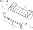
- FIG. 12 is a perspective view when the upper-part case member, the lower-part case member and the primary conductor are removed from the electric current detector relating to the example 5. It should be noted that other constitutions of the electric current detector relating to the example 5 are similar to any one of those examples 1 to 4 and therefore, the explanation thereof will be omitted.
- a magnetic shield member 201 is arranged between the core 4 and the case (the lower-part case member 2, in other words, the support member of the core 4). It should be noted that the magnetic shield member 201 is arranged spaced from the core so as not to make contact with the core 4. For example, the magnetic shield member may be fixed on the core 4 or the lower-part case member 2 through an adhesive agent, a nonmagnetic member or the like.
- the magnetic shield member 201 includes a flat plate-shaped top surface portion 201a and two facing flat plate-shaped side surface portions 201b. Each of the side surface portions 201b extends perpendicularly from the top surface portion 201a.
- the magnetic shield member 201 is constituted by using a single member, but it is allowed to constitute it by using a plurality of members (separate members which correspond to the top surface portion 201a and the side surface portions 201b).
- the magnetic shield member 201 does not interlink with the primary conductors 3.
- the top surface portion 201a of the magnetic shield member 201 is arranged on the upper side of the gap 41, 82 or 92 of the core 4, 81 or 91 (that is, upper side of the magnetic sensor IC chip 111) and the side surface portions 201b of the magnetic shield member 201 are arranged on the sides of the gap 41, 82 or 92 of the core 4, 81 or 91 (that is, on the sides of the magnetic sensor IC chip 111).
- the magnetic shield member 201 is constituted, for example, by a material such as a ferrite (Ni-Zn-based ferrite, Mn-Zn-based ferrite, Ba-based ferrite, ferox planar ferrite or the like), an amorphous magnetic alloy, a silicon steel sheet, a permalloy, a nanocrystal magnetic alloy or the like.
- a ferrite Ni-Zn-based ferrite, Mn-Zn-based ferrite, Ba-based ferrite, ferox planar ferrite or the like
- an amorphous magnetic alloy such as a silicon steel sheet, a permalloy, a nanocrystal magnetic alloy or the like.
- a first manufacturer manufactures and sells any one of the electric current detectors of the above-mentioned examples 1 to 5; a second manufacturer manufactures and sells the above-mentioned magnetic sensor IC chip 111; and a third manufacturer purchases those electric current detector and magnetic sensor IC chip 111, mounts those electric current detector and magnetic sensor IC chip 111 and the above-mentioned electric-current measurement circuit on the circuit board 101, and manufactures the electronic equipment.
- the third manufacturer mounts the above-mentioned electric current detector and electric-current measurement circuit after determining the number of the primary conductors 3 which are serially connected to one another, the measurement range of the above-mentioned electric-current measurement circuit and the like in response to the range of the electric-current values of the electric current which becomes a detection target in that electronic equipment.
- the electric current detector is constituted in a manner mentioned above and, therefore, by forming the above-mentioned fixing hole 103 on the circuit board 101 of the electronic equipment which is manufactured by the third manufacturer in conformity with the positional relation between the fixing protrusion 21 and the gap 41 of that electric current detector and concurrently, by mounting the magnetic sensor IC chip 111 thereon and by mounting that electric current detector onto the circuit board 101, it is possible for the third manufacturer to install the electric current detector simply in the inside of that electronic equipment in conformity with the specification of that electronic equipment.
- a nonmagnetic spacer in the gap 41, 82 or 92, or it is allowed to fill a nonmagnetic adhesive agent or a filler material therein.
- a soft magnetic adhesive agent or a filler material in a portion of the gap 41, 82 or 92 on the upper surface side of the core 4, 81 or 91 (in a space between a portion of one end surface and a portion of the other end surface, which constitute the gap 41, 82 or 92.
- the core 4, 81 or 91 is constituted by the two symmetrical core members 4a and 4b, 81a and 81b or 91a and 91b, but it is allowed to constitute the core by using a plurality of asymmetrical core members.
- the core 4, 81 or 91 is constituted by the two symmetrical core members 4a and 4b, 81a and 81b or 91a and 91b, so that the gap 41, 82 or 92 is arranged at the center position, but in the case of using a plurality of asymmetrical core members, it is allowed for the gap 41, 82 or 92 not to be arranged at the center position.
- the electric-current value is detected based on a magnetic balance system, but it is allowed to detect the electric-current value based on a magnetic proportion system. In that case, it is allowed not to provide the bobbin 5, the compensating coil 6 and the like.
- the present invention is applicable, for example, to an electric current sensor.
Landscapes
- Physics & Mathematics (AREA)
- General Physics & Mathematics (AREA)
- Engineering & Computer Science (AREA)
- Power Engineering (AREA)
- Measuring Instrument Details And Bridges, And Automatic Balancing Devices (AREA)
Abstract
Description
- The present invention contains subject matters related to Japanese Patent Applications
JP2015-089092 JP2016-034974 - The present invention relates to an electric current detector.
- A certain electric current sensor based on a magnetic balance system includes a vertical-type (that is, vertically placed) annular core, a primary conductor is arranged so as to interlink with that annular core, and a compensating coil (secondary coil) is installed on the annular core. Further, a cavity is provided at the bottom portion of the annular core and a stick-shaped fluxgate-type sensor is inserted into that cavity. A control circuit board for driving that sensor is provided separately from the circuit board on which this electric current sensor is mounted and is connected to that sensor (for example, see Patent Document 1: Japanese unexamined
PCT publication No. 2011-510318 - On the other hand, for the fluxgate-type magnetic sensor, other than the above-mentioned rod-shaped sensor for a special application, there exists an IC-chip shaped sensor with a built-in circuit structure as described, for example, in Patent Document 2 (
US unexamined patent publication No. 2014/0218018 ). - However, the above-mentioned electric current sensor uses a vertical-type annular core and therefore, is configured to have a high profile, in which in the case of installing this electric current sensor on a circuit board, a space is required on the upper side of the circuit board in conformity with the height of this electric current sensor.
- The present invention was invented in view of the aforesaid problem and is addressed to obtain a low-profile electric current detector.
- The electric current detector relating to the present invention is an electric current detector which is mountable on a circuit board on which there is mounted a fluxgate-type magnetic sensor IC chip which detects magnetic flux for electric current detection, in which there is included a substantially ring-shaped core which forms a magnetic-path for magnetic flux induced by detection-target electric current. Then, the core includes a gap which is arranged to become substantially parallel with respect to the circuit board when mounting the aforesaid electric current detector on the circuit board and which is at a place positioned on or on the upper side of the magnetic sensor IC chip in the magnetic-path when mounting the aforesaid electric current detector on the circuit board.
- According to the present invention, it is possible to obtain a low-profile electric current detector.
-
-
FIG. 1 is a perspective view showing an electric current detector relating to an example 1 of the present invention; -
FIG. 2 is a perspective view showing a bottom surface of the electric current detector relating to the example 1 of the present invention; -
FIG. 3 is a perspective view showing an inner surface of an upper-part case member inFIG. 1 ; -
FIG. 4 is a perspective view when the upper-part case member and primary conductors of the electric current detector shown inFIG. 1 are removed; -
FIG. 5 is a perspective view showing acore 4 and acompensating coil 6 of the electric current detector shown inFIG. 1 ; -
FIG. 6 is a perspective view showing one example of a circuit board which is mounted with the electric current detector relating to the example 1; -
FIG. 7 is a side view showing the electric current detector mounted on acircuit board 101 relating to the example 1; -
FIG. 8 is a drawing which explains an electric current detection operation of the electric current detector relating to the example 1; -
FIG. 9 is a perspective view showing a core of an electric current detector relating to an example 3 of the present invention; -
FIG. 10 is a side view showing one example of a core of an electric current detector relating to an example 4 of the present invention; -
FIG. 11 is a perspective view when the upper-part case member and the primary conductor are removed from an electric current detector relating to an example 5; and -
FIG. 12 is a perspective view when the upper-part case member, the lower-part case member and the primary conductor are removed from the electric current detector relating to the example 5. - Hereinafter, there will be explained examples of the present invention based on the drawings.
-
FIG. 1 is a perspective view showing an electric current detector relating to an example 1 of the present invention.FIG. 2 is a perspective view showing a bottom surface of the electric current detector relating to the example 1 of the present invention.FIG. 3 is a perspective view showing an inner surface of an upper-part case member inFIG. 1 .FIG. 4 is a perspective view when the upper-part case member and primary conductors of the electric current detector shown inFIG. 1 are removed. - The electric current detector relating to the example 1 is an electric current detector which is mountable on a circuit board on which a fluxgate-type magnetic sensor IC chip for detecting magnetic flux for the electric current detection is to be mounted.
- As shown in
FIGS. 1 and2 , the electric current detector relating to the example 1 includes an upper-part case member 1 and a lower-part case member 2. The upper-part case member 1 includesgrooves 11 which are continuous between the upper surface thereof and one side surface thereof. In thegrooves 11,primary conductors 3 are arranged. - As shown in
FIG. 1 , the upper-part case member 1 is mounted on the lower-part case member 2. Thus, the upper-part case member 1 and the lower-part case member 2 become integrated and constitute a case. As shown inFIG. 2 , depending on a mechanism in whichclaw portions 12 at the distal ends on the facing two side surfaces of the upper-part case member 1 are fitted with the lower-part case member 2, the upper-part case member 1 is fixed on the lower-part case member 2. - The
primary conductor 3 is a metal member through which detection-target electric current Ip conducts. InFIG. 1 , theprimary conductors 3 are formed by four lines, but it is allowed to employ a single line, or the number of the lines can be selected as required by the application. In addition, it is also allowed to employ a bus bar for theprimary conductor 3. - As shown in
FIG. 3 , the upper-part case member 1 includes a guidingconvex portion 13 which stands upright from its ceiling surface and the guidingconvex portion 13 includes the same number ofguide holes 14 compared with thegrooves 11. Theguide hole 14 is formed so as to be continuous with thegroove 11 and theprimary conductor 3 is arranged along thegroove 11 and theguide hole 14. - In addition, as shown in
FIG. 4 , acore 4 which is mounted with acompensating coil 6 by abobbin 5 is fixed on the inside of the lower-part case member 2. The compensatingcoil 6 is wound around thebobbin 5. The lower-part case member 2 has a substantially square plate flatbottom surface portion 2a and four substantially-flat plate-shapedside surface portions 2b which stand upright and extend from thebottom surface portion 2a. Thecore 4 mounted with thebobbin 5 and the compensatingcoil 6 is fitted between theside surface portions 2b, is arranged substantially parallel with respect to thebottom surface portion 2a of the lower-part case member 2 and is fixed on the lower-part case member 2. - In this example 1, the
core 4 is fixed directly on the lower-part case member 2, but it is allowed to fix thecore 4 indirectly on the lower-part case member 2 by using a separate attaching member. It should be noted that it is also allowed for thecore 4 to be provided so as to be fixed on the lower-part case member 2 by an adhesive agent. -
FIG. 5 is a perspective view showing acore 4 and acompensating coil 6 of the electric current detector shown inFIG. 1 . - The
core 4 is substantially a ring-shaped core which forms a magnetic-path for the magnetic flux Tp induced by the detection-target electric current Ip. In this example, thecore 4 includes a plurality ofcore members core member 4a and one end surface of thecore member 4b, there exists agap 41 and the other end surface of thecore member 4a and the other end surface of thecore member 4b are joined to each other. - The two end surfaces which define the
gap 41 in thecore 4 are formed substantially perpendicularly with respect to the magnetic-path formed by thecore 4 and, thus, are formed substantially perpendicularly with respect to thebottom surface portion 2a of the lower-part case member 2. - In addition, the leg portions of the
core members gap 41 each include aprotrusion portion 42 protruding toward the lower side (bottom surface side) and, concurrently, include a cut-outportion 43 having substantially the same shape as that of theprotrusion portion 42. - In addition, in this example 1, the size H1 in the height direction of the other leg portion of the
core member core member bobbin 5 and thecompensating coil 6 will not protrude from the bottom surface of thecore 4 when thebobbin 5 and compensatingcoil 6 are mounted on thecore 4, and this configuration contributes to the low-profile of the aforesaid electric current detector. - It should be noted that it is allowed to form the width H1 in the height direction of the other leg portion of the
core member protrusion portion 42 is made to increase corresponding to the protrusion height of thebobbin 5 and that of thecompensating coil 6 from the bottom surface of thecore 4. - In this example, the
core 4 is a ferrite core. As shown inFIG. 5 , the shape of thecore 4 is not complicated and therefore, it is possible to manufacture thecore member core 4 is not limited to ferrite material. - For example, in a case in which a complicated core shape becomes necessary, like the core described in the Patent Document 1 (Japanese unexamined
PCT publication No. 2011-510318 core 4 by a ferrite core. It should be noted that in the case of a ferrite core, the magnetic flux density is non-linear with respect to the magnetic-field strength (that is, detection-target electric current), but the magnetic flux density in thecore 4 on an occasion of the electric current detection will decrease by detecting the electric current based on a magnetic balance system, so that there will be no problem in particular. - The
core 4 is substantially a ring-shaped core which forms a magnetic-path for the magnetic flux Tp induced by the detection-target electric current Ip. In this example, thecore 4 includes a plurality ofcore members core member 4a and one end surface of thecore member 4b, there exists agap 41 and the other end surface of thecore member 4a and the other end surface of thecore member 4b are joined to each other. - The
bobbin 5 is a resin-made bobbin provided withterminals coil 6 electrically. Theterminals coil 6 electrically and theterminals coil 6 electrically. Thebobbin 5 has an openingportion 55 and the compensatingcoil 6 is mounted on thecore 4 by passing the respective one leg portions of thecore members portion 55. - In order to detect the electric current by the magnetic balance system, the compensating
coil 6 induces, in thecore 4, a magnetic flux Tc for cancelling the magnetic flux Tp which is induced in thecore 4 by the electric current Ip in theprimary conductor 3. The compensatingcoil 6 induces the magnetic flux Tc in thecore 4 by the electric current inputted by using theterminals 51 to 54. - In addition, as shown in
FIG. 2 , the lower-part case member 2 includes fixingprotrusions 21 for fixing the aforesaid electric current detector onto a circuit board, which will be mentioned later. In other words, the lower-part case member 2 supports thecore 4 and concurrently, functions as a support member which is mountable onto a circuit board. Further, the lower-part case member 2 includes an openingportion 22 on the lower side of the arrangement position of thegap 41 of thecore 4. Thus, the peripheries of thegap 41 of thecore 4 are exposed from the openingportion 22. In addition, as shown inFIG. 4 , the lower-part case member 2 includes aguide sleeve 23 which stands upright from the inner bottom surface thereof. The hollow portion of theguide sleeve 23 penetrates thebottom surface portion 2a of the lower-part case member 2 and when mounting the upper-part case member 1 on the lower-part case member 2, the guidingconvex portion 13 of the upper-part case member 1 is inserted into the hollow portion of theguide sleeve 23 in which the distal end of the guidingconvex portion 13 is exposed as shown inFIG. 2 . - Thus, the
primary conductors 3 are arranged along the guide holes 14 of the guidingconvex portion 13 and therefore, theprimary conductors 3 are interlinked with thecore 4. -
FIG. 6 is a perspective view showing one example of a circuit board which is mounted with the electric current detector relating to the example 1. As shown inFIG. 6 , acircuit board 101 is mounted with a magnetic sensor IC (Integrated Circuit)chip 111 at a predetermined position and further, includes fixingholes 102 at the positions corresponding to those of the fixingprotrusions 21. In addition, thecircuit board 101 includesholes 103 for passing theprimary conductors 3 therethrough and holes 104 for passing theterminals - It should be noted in this example 1 that the electric current detector is mounted and fixed on the
circuit board 101 by the fixingprotrusions 21 and the fixingholes 102, but it is allowed to employ a configuration in which holes are formed instead of the fixingprotrusions 21 and those holes and the fixingholes 102 are to be connected by means of other separate members such as spacers or the like so as to be fixed mutually. - The magnetic
sensor IC chip 111 is a fluxgate-type magnetic sensor IC chip which detects magnetic flux for the electric current detection. For example, this magneticsensor IC chip 111 may have a built-in fluxgate-type magnetic sensor which is described in the Patent Document 2 (US unexamined patent publication No. 2014/0218018 ). - The magnetic
sensor IC chip 111 is, for example, soldered onto a wiring pattern (not shown) on thecircuit board 101 and, thus, the chip is fixed on thecircuit board 101. This magneticsensor IC chip 111 detects the magnetic flux which is in parallel with the mounting face (that is, in parallel with the bottom surface and the upper surface of the package of the magnetic sensor IC chip 111). - The magnetic
sensor IC chip 111 is fixed at a predetermined position with respect to the fixingholes 102 in consideration of the positional relation between the fixingprotrusions 21 of the above-mentioned electric current detector and thegap 41 of thecore 4 such that the magneticsensor IC chip 111 will be arranged immediately under thegap 41 of thecore 4 when mounting the above-mentioned electric current detector on thecircuit board 101. - In other words, when the aforesaid electric current detector is mounted on the
circuit board 101, thegap 41 is arranged at a place which is in contact with the upper surface of the magneticsensor IC chip 111 in the magnetic-path formed by thecore 4 or which is positioned on the upper side of the magneticsensor IC chip 111 therein. - In addition, as shown in
FIG. 5 , there is employed a configuration in which the distance between thegap 41 and the magneticsensor IC chip 111 when mounting the aforesaid electric current detector on the circuit board by theprotrusion portion 42 of thecore 4 will decrease, so that it becomes a state in which the magneticsensor IC chip 111 can easily detect the leakage magnetic flux caused by thegap 41. - Further, in the aforesaid electric current detector, the
core 4 is fixed substantially parallel with respect to thebottom surface portion 2a of the lower-part case member and in addition, thebottom surface portion 2a and thecircuit board 101 become substantially parallel with each other when mounting the aforesaid electric current detector on the circuit board 101 (in other words, when mounting the lower-part case member 2 on the circuit board 101). Therefore, thecore 4 is arranged so as to become substantially parallel with respect to thecircuit board 101, that is, so as to be placed horizontally when mounting the aforesaid electric current detector on the circuit board 101 (in other words, when mounting the lower-part case member 2 on the circuit board 101). Two end surfaces constituting thegap 41 of thecore 4 become substantially perpendicular with respect to thecircuit board 101 and the magneticsensor IC chip 111. - Next, there will be explained an operation of the electric current detector relating to the example 1.
FIG. 7 is a side view showing the electric current detector mounted on thecircuit board 101 relating to the example 1.FIG. 8 is a drawing which explains an electric current detection operation of the electric current detector relating to the example 1. - As shown in
FIG. 7 , the electric current detector relating to the example 1 is mounted on thecircuit board 101 and circuits and the like which output the detection-target electric current are electrically connected to theprimary conductors 3. In addition, an electric-current measurement circuit which drives the compensatingcoil 6 in response to the magnetic flux detected by the magneticsensor IC chip 111 is provided on thecircuit board 101. That electric-current measurement circuit is electrically connected to the magneticsensor IC chip 111 and theterminals - As shown in
FIG. 8 , on an occasion of the electric current detection, the magnetic flux Tp is induced inside thecore 4 by the detection-target electric current Ip conducting through theprimary conductor 3 and the leakage magnetic flux in the vicinity of thegap 41 passes through the magneticsensor IC chip 111. In this manner, the magnetic flux in response to the detection-target electric current Ip is made to conduct through the magneticsensor IC chip 111. Then, the magneticsensor IC chip 111 generates a compensation electric current caused by this leakage magnetic flux. Then, the compensatingcoil 6 induces the magnetic flux Tc inside thecore 4 such that, based on this compensation electric current, the magnetic flux will become zero. Then, the electric-current value of the detection-target electric current Ip is specified based on the electric-current value of the compensatingcoil 6 when the magnetic flux detected by the magneticsensor IC chip 111 has become zero. - As mentioned above, the electric current detector relating to the aforesaid example 1 includes the substantially ring-shaped
core 4 which is mountable on thecircuit board 101 on which there is mounted the fluxgate-type magneticsensor IC chip 111 which detects the magnetic flux for the electric current detection, and which forms the magnetic-path for the magnetic flux induced by the detection-target electric current. Then, thecore 4 includes thegap 41 which is arranged to become substantially parallel with respect to thecircuit board 101 when mounting the aforesaid electric current detector on thecircuit board 101 and which is at a place positioned on or on the upper side of the magneticsensor IC chip 111 in the magnetic-path caused by thecore 4 when mounting the aforesaid electric current detector on thecircuit board 101. - Thus, the
gap 41 is arranged in close proximity to the magneticsensor IC chip 111 which is surface-mounted on thecircuit board 101 and thecore 4 is placed horizontally and therefore, there can be obtained a low-profile electric current detector. - An electric current detector relating to an example 2 of the present invention includes similar constituent elements to those of the electric current detector relating to the example 1. However, in the example 2, the upper-
part case member 1 and the lower-part case member 2 have magnetic shielding functions. - In the example 2, the upper-
part case member 1 and the lower-part case member 2 are formed by a soft magnetic material having high permeability such as permalloy or the like. It should be noted that it is allowed for only the upper-part case member 1 or only the lower-part case member 2 to be formed by the soft magnetic material. - However, a portion of the side surfaces of the upper-
part case member 1 and the lower-part case member 2 is formed by a non-magnetic material such that there is not formed a circulating magnetic-path with respect to theprimary conductors 3. Similarly, a portion of the upper surface of the upper-part case member 1 and the bottom surface of the lower-part case member 2 is formed by a non-magnetic material such that there is not formed a circulating magnetic-path with respect to theprimary conductors 3. For example, for the upper-part case member 1 and the lower-part case member 2, predetermined portions thereof which extend substantially perpendicularly with respect to the direction of the circulating magnetic flux caused by the detection-target electric current Ip are formed by a non-magnetic material such as a resin or the like. - Even if the upper-
part case member 1 and the lower-part case member 2 are formed by a magnetic material in this manner, there are provided anopening portion 22 on thebottom surface portion 2a of the lower-part case member 2 at the arrangement-position of thegap 41 of thecore 4 and, therefore, the leakage magnetic flux from thegap 41 conducts through the magneticsensor IC chip 111. - As mentioned above, according to the aforesaid example 2, the upper-
part case member 1 and the lower-part case member 2 have magnetic shielding functions and therefore, there will be decreased the influence of the disturbance magnetic flux induced by the electric current which conducts in the vicinity thereof. -
FIG. 9 is a perspective view showing a core of an electric current detector relating to an example 3 of the present invention. The electric current detector relating to the example 3 includes a core 81 as shown inFIG. 9 instead of thecore 4. It should be noted that other constitutions of the electric current detector relating to the example 3 are similar to those of the example 1 or the example 2 and, therefore, the explanation thereof will be omitted. - In the example 3, the
core 81 is a substantially ring-shaped core which forms a magnetic-path for the magnetic flux Tp induced by the detection-target electric current Ip. In this example, thecore 81 includes a plurality ofcore members gap 82 between one end surface of thecore member 81a and one end surface of thecore member 81b, whereas the other end surface of thecore member 81a and the other end surface of thecore member 81b are joined to each other. - In addition, each of one-side leg portions of the core members 82a, 82b forming the
gap 82 includes aprotrusion portion 83 which protrudes toward the lower side (bottom surface side) and, concurrently, includes a cut-outportion 84 having substantially the same shape as that of theprotrusion portion 83. Further, in the example 3, theprotrusion portions 83 include cut-outportions 85 which are formed in conformity with the shape of the magneticsensor IC chip 111. The cut-outportions 85 are formed in a shape for covering a portion of or all of the side surfaces of the magneticsensor IC chip 111 when the aforesaid electric current detector is mounted on thecircuit board 101. For example, the cut-outportion 85 may have substantially the same height as the height of the magnetic sensor IC chip 111 (that is, the distance from the surface of thecircuit board 101 to the upper surface of the package of the magnetic sensor IC chip 111). - It should be noted that the core 81 shown in
FIG. 9 covers the upper surface and two side surfaces of the magneticsensor IC chip 111, but it is allowed for the core to be formed in a shape which covers the upper surface and four side surfaces of the magneticsensor IC chip 111. -
FIG. 10 is a side view showing one example of a core of an electric current detector relating to an example 4 of the present invention. The electric current detector relating to the example 4 includes a core 91 shown inFIG. 10 instead of thecore 4. It should be noted that other constitutions of the electric current detector relating to the example 4 are similar to those of the example 1 or the example 2 and therefore, the explanation thereof will be omitted. - In the example 4, the
core 91 is a substantially ring-shaped core which forms a magnetic-path for the magnetic flux Tp induced by the detection-target electric current Ip. In this example, thecore 91 includes a plurality ofcore members gap 92 between one end surface of thecore member 91a and one end surface of thecore member 91b, whereas the other end surface of thecore member 91a and the other end surface of thecore member 91b are joined each other. - Further, in the example 4, the width of the
gap 92 changes along the height direction and the more thegap 92 goes to the bottom surface side of the core 91, the wider the gap becomes. It should be noted that the shapes other than the shape of thegap 92 of the core 91 are similar to those of thecore 4. - It should be noted that in the core 91 shown in
FIG. 10 , the end surfaces of thecore members gap 92 are formed in step shapes, but it is allowed to form the end surfaces in inclined slope-surface shapes or in curved surface shapes. - The electric current detector relating to an example 5 of the present invention is a detector which further includes a plate-shaped magnetic shield member for any one of the examples 1 to 4.
-
FIG. 11 is a perspective view when the upper-part case member 1 and theprimary conductor 3 are removed from an electric current detector relating to the example 5.FIG. 12 is a perspective view when the upper-part case member, the lower-part case member and the primary conductor are removed from the electric current detector relating to the example 5. It should be noted that other constitutions of the electric current detector relating to the example 5 are similar to any one of those examples 1 to 4 and therefore, the explanation thereof will be omitted. - As shown in
FIG. 11 andFIG. 12 , amagnetic shield member 201 is arranged between thecore 4 and the case (the lower-part case member 2, in other words, the support member of the core 4). It should be noted that themagnetic shield member 201 is arranged spaced from the core so as not to make contact with thecore 4. For example, the magnetic shield member may be fixed on thecore 4 or the lower-part case member 2 through an adhesive agent, a nonmagnetic member or the like. - As shown in
FIG. 12 , themagnetic shield member 201 includes a flat plate-shapedtop surface portion 201a and two facing flat plate-shapedside surface portions 201b. Each of theside surface portions 201b extends perpendicularly from thetop surface portion 201a. In this example 5, themagnetic shield member 201 is constituted by using a single member, but it is allowed to constitute it by using a plurality of members (separate members which correspond to thetop surface portion 201a and theside surface portions 201b). Themagnetic shield member 201 does not interlink with theprimary conductors 3. In addition, thetop surface portion 201a of themagnetic shield member 201 is arranged on the upper side of thegap core side surface portions 201b of themagnetic shield member 201 are arranged on the sides of thegap core - The
magnetic shield member 201 is constituted, for example, by a material such as a ferrite (Ni-Zn-based ferrite, Mn-Zn-based ferrite, Ba-based ferrite, ferox planar ferrite or the like), an amorphous magnetic alloy, a silicon steel sheet, a permalloy, a nanocrystal magnetic alloy or the like. - By providing the
magnetic shield member 201 in this manner, there will be decreased the influence of the disturbance magnetic flux induced by the electric current which conducts in the vicinity thereof. - In a manufacturing method of an electronic equipment relating to an example 6 of the present invention, a first manufacturer manufactures and sells any one of the electric current detectors of the above-mentioned examples 1 to 5; a second manufacturer manufactures and sells the above-mentioned magnetic
sensor IC chip 111; and a third manufacturer purchases those electric current detector and magneticsensor IC chip 111, mounts those electric current detector and magneticsensor IC chip 111 and the above-mentioned electric-current measurement circuit on thecircuit board 101, and manufactures the electronic equipment. At that time, the third manufacturer mounts the above-mentioned electric current detector and electric-current measurement circuit after determining the number of theprimary conductors 3 which are serially connected to one another, the measurement range of the above-mentioned electric-current measurement circuit and the like in response to the range of the electric-current values of the electric current which becomes a detection target in that electronic equipment. - The electric current detector is constituted in a manner mentioned above and, therefore, by forming the above-mentioned
fixing hole 103 on thecircuit board 101 of the electronic equipment which is manufactured by the third manufacturer in conformity with the positional relation between the fixingprotrusion 21 and thegap 41 of that electric current detector and concurrently, by mounting the magneticsensor IC chip 111 thereon and by mounting that electric current detector onto thecircuit board 101, it is possible for the third manufacturer to install the electric current detector simply in the inside of that electronic equipment in conformity with the specification of that electronic equipment. - It should be noted that it is self-evident for a person skilled in the art to apply various changes and modifications with respect to the examples mentioned above. Such changes and modifications may be applied without being apart from the gist and the scope of the main subject thereof and also without reducing the intended advantages. In other words, it is intended that such changes and modifications are to be included within the scope of the claims.
- For example, in the aforesaid examples 1 to 5, for the end surfaces joining each other which are respectively different from the end surfaces forming the
gap core members FIG. 5 . In addition, it is allowed to join those end surfaces to each other by a magnetic adhesive agent. - In addition, in the aforesaid examples 1 to 5, it is allowed to arrange a nonmagnetic spacer in the
gap gap core gap - In addition, in the aforesaid examples 1 to 5, in order to decrease the influence of disturbance, it is allowed to arrange a magnetic sheet of a soft magnetic material between the
circuit board 101 and the magneticsensor IC chip 111, to paste a magnetic sheet of a soft magnetic material on the rear surface of the circuit board 101 (the surface on the opposite side of the mounting face of the magnetic sensor IC chip 111), and so on. In addition, it is allowed for thecircuit board 101 to use a circuit board including a magnetic layer having a soft magnetic material. - In addition, in the aforesaid examples 1 to 5, the
core symmetrical core members core core symmetrical core members gap gap - In addition, in the aforesaid examples 1 to 5, the electric-current value is detected based on a magnetic balance system, but it is allowed to detect the electric-current value based on a magnetic proportion system. In that case, it is allowed not to provide the
bobbin 5, the compensatingcoil 6 and the like. - The present invention is applicable, for example, to an electric current sensor.
- Having described preferred embodiments of the invention with reference to the accompanying drawings, it is to be understood that the invention is not limited to those precise embodiments and that various changes and modifications could be effected therein by one skilled in the art without departing from the scope of the invention as defined in the appended claims.
Claims (7)
- An electric current detector which is mountable on a circuit board (101) on which there is mounted a fluxgate-type magnetic sensor IC chip (111) which detects magnetic flux for electric current detection, the electric current detector comprising:a substantially ring-shaped core (4, 81, 91) which forms a magnetic-path for magnetic flux induced by detection-target electric current, whereinthe core (4, 81, 91) includes a gap (41, 82, 92) which is arranged to become substantially parallel with respect to the circuit board (101) when the electric current detector is mounted on the circuit board (101) and which is at a place arranged to be positioned on, or on the upper side of, the magnetic sensor IC chip (111) in the magnetic-path when the electric current detector is mounted on the circuit board (101).
- The electric current detector according to claim 1, further comprising:a support member (2) mountable on the circuit board, whereinthe core (4, 81, 91) is fixed directly or indirectly on the support member (2), andthe gap (41, 82, 92) is at a place arranged to be positioned on, or on the upper side of, the magnetic sensor IC chip (111) in the magnetic-path when the support member (2) is mounted on the circuit board (101).
- The electric current detector according to claim 1 or claim 2, wherein two end surfaces which define the gap (41, 82, 92) in the core (4, 81, 91) are arranged to be substantially perpendicular with respect to the circuit board (101) when the electric current detector is mounted on the circuit board (101).
- The electric current detector according to any one of claims 1 to 3, further comprising:a primary conductor (3) which is arranged so as to be interlinked with the core (4, 81, 91) and through which a detection-target electric current conducts; anda compensating coil (6) which induces a magnetic flux inside the core (4, 81, 91) for cancelling the magnetic flux induced inside the core (4, 81, 91) by the electric current of the primary conductor (3), whereinthe electric current is detected based on a magnetic balance system.
- The electric current detector according to any one of claims 2 to 4, wherein the support member (2) is a portion of or all of the case which houses the core (4, 81, 91),
the case (2) has a magnetic shielding function, and
the case (2) includes an opening portion on the bottom surface (2a) of the case (2) at an arrangement-position of the gap (41, 82, 92) in the core (4, 81, 91). - The electric current detector according to any one of claims 2 to 4, further comprising:a plate-shaped magnetic shield member (201), whereinthe support member is a portion of or all of the case (2) which houses the core (4, . 81, 91), andthe magnetic shield member (201) is arranged between the core (4, 81, 91) and the case (2).
- The electric current detector according to any one of claims 1 to 6, wherein the core (4, 81, 91) is a ferrite core.
Applications Claiming Priority (2)
| Application Number | Priority Date | Filing Date | Title |
|---|---|---|---|
| JP2015089092 | 2015-04-24 | ||
| JP2016034974A JP6531951B2 (en) | 2015-04-24 | 2016-02-26 | Current detection device |
Publications (2)
| Publication Number | Publication Date |
|---|---|
| EP3086129A1 true EP3086129A1 (en) | 2016-10-26 |
| EP3086129B1 EP3086129B1 (en) | 2019-06-19 |
Family
ID=55808432
Family Applications (1)
| Application Number | Title | Priority Date | Filing Date |
|---|---|---|---|
| EP16166471.9A Active EP3086129B1 (en) | 2015-04-24 | 2016-04-21 | Electric current detector |
Country Status (3)
| Country | Link |
|---|---|
| US (1) | US9939465B2 (en) |
| EP (1) | EP3086129B1 (en) |
| CN (1) | CN106066420B (en) |
Cited By (3)
| Publication number | Priority date | Publication date | Assignee | Title |
|---|---|---|---|---|
| CN112119316A (en) * | 2017-10-02 | 2020-12-22 | Abb瑞士股份有限公司 | Flux Absorbers for Power Line Equipment |
| US11614471B2 (en) | 2018-08-16 | 2023-03-28 | Phoenix Contact Gmbh & Co. Kg | Current measuring device for detecting a current in an electric line |
| US11656248B2 (en) | 2018-08-16 | 2023-05-23 | Phoenix Contact Gmbh & Co. Kg | Current meter for detecting currents in electrical lines |
Families Citing this family (12)
| Publication number | Priority date | Publication date | Assignee | Title |
|---|---|---|---|---|
| WO2018230030A1 (en) * | 2017-06-14 | 2018-12-20 | 三菱電機株式会社 | Current detection device and power conversion apparatus |
| JP7496773B2 (en) * | 2017-08-09 | 2024-06-07 | ヴェルディグリス テクノロジーズ インコーポレイテッド | Current Transformers and Power Distribution Systems |
| JP6919609B2 (en) * | 2018-03-20 | 2021-08-18 | 株式会社デンソー | Current sensor |
| JP7396787B2 (en) * | 2018-04-04 | 2023-12-12 | スミダコーポレーション株式会社 | Microcurrent detection device and microcurrent detection method |
| JP7519586B2 (en) * | 2019-04-24 | 2024-07-22 | パナソニックIpマネジメント株式会社 | Current Sensors |
| JP7194083B2 (en) * | 2019-07-01 | 2022-12-21 | 株式会社タムラ製作所 | Electronics and current detectors |
| JP7109407B2 (en) * | 2019-07-01 | 2022-07-29 | 株式会社タムラ製作所 | current detector |
| CN111220844A (en) * | 2020-01-20 | 2020-06-02 | 东风汽车集团有限公司 | Non-contact three-phase current detection system |
| CN113721067A (en) * | 2021-10-08 | 2021-11-30 | 国网西藏电力有限公司 | Arc current detection device for plateau power distribution overhead line |
| JP2023060610A (en) * | 2021-10-18 | 2023-04-28 | Tdk株式会社 | magnetic sensor |
| CN114594290A (en) * | 2022-04-06 | 2022-06-07 | 宁波泰丰源电气有限公司 | Direct current sensor with elbow connector output |
| CN115656602B (en) * | 2022-10-21 | 2025-04-01 | 宁波中车时代传感技术有限公司 | Current sensor and method for manufacturing the same |
Citations (7)
| Publication number | Priority date | Publication date | Assignee | Title |
|---|---|---|---|---|
| WO2001040812A2 (en) * | 1999-11-30 | 2001-06-07 | Honeywell Control Systems Ltd. | Current sensor and method of manufacturing same |
| EP1450176A1 (en) * | 2003-02-21 | 2004-08-25 | Liaisons Electroniques-Mecaniques Lem S.A. | Magnetic field sensor and electrical current sensor therewith |
| JP2008224260A (en) * | 2007-03-09 | 2008-09-25 | Tamura Seisakusho Co Ltd | Electric current detector |
| JP2011510318A (en) | 2008-01-25 | 2011-03-31 | リエゾン、エレクトロニク−メカニク、エルウエム、ソシエテ、アノニム | Current sensor |
| US20120306486A1 (en) * | 2011-05-30 | 2012-12-06 | Melexis Technologies Nv | Device for measuring a current flowing through an electric cable |
| US20140218018A1 (en) | 2013-02-05 | 2014-08-07 | Texas Instruments Deutschland Gmbh | Apparatus and method for in situ current measurement in a conductor |
| US20140266180A1 (en) * | 2013-03-15 | 2014-09-18 | Infineon Technologies Ag | Sensors, systems and methods for residual current detection |
Family Cites Families (12)
| Publication number | Priority date | Publication date | Assignee | Title |
|---|---|---|---|---|
| JPH08233922A (en) * | 1995-02-28 | 1996-09-13 | Minerva:Kk | Magnetic head |
| CH692161A5 (en) * | 1997-07-04 | 2002-02-28 | Lem Liaisons Electron Mec | current sensor. |
| DE69920890T2 (en) * | 1999-01-21 | 2005-02-03 | Tdk Corp. | CURRENT SENSOR |
| DE10013143C2 (en) * | 2000-03-17 | 2002-06-27 | Aeg Niederspannungstech Gmbh | transducers |
| EP1498739B1 (en) * | 2003-07-12 | 2006-04-05 | Liaisons Electroniques-Mecaniques Lem S.A. | Current sensor having a magnetic core with airgap and power supply circuit provided with such sensors |
| ATE435427T1 (en) * | 2005-02-22 | 2009-07-15 | Trench Switzerland Ag | TOIR CORE CURRENT TRANSFORMER WITH PHASE COMPENSATION CIRCUIT |
| KR101433212B1 (en) * | 2010-04-14 | 2014-08-22 | 지멘스 악티엔게젤샤프트 | Method and apparatus for detecting a magnetic characteristic variable in a core |
| DK2515123T3 (en) * | 2011-04-21 | 2016-10-31 | Abb Ag | Current sensor that works according to the compensation principle |
| JP2013015431A (en) * | 2011-07-05 | 2013-01-24 | Sumitomo Wiring Syst Ltd | Current detecting device |
| EP2660611A1 (en) * | 2012-04-30 | 2013-11-06 | LEM Intellectual Property SA | Electrical current transducer module |
| EP2680013B1 (en) * | 2012-06-28 | 2014-10-15 | LEM Intellectual Property SA | Electrical current transducer |
| CN103576030B (en) * | 2013-11-12 | 2016-03-30 | 国家电网公司 | A kind of transformer online monitoring sensor |
-
2016
- 2016-04-20 US US15/133,761 patent/US9939465B2/en active Active
- 2016-04-21 EP EP16166471.9A patent/EP3086129B1/en active Active
- 2016-04-22 CN CN201610258371.9A patent/CN106066420B/en not_active Expired - Fee Related
Patent Citations (7)
| Publication number | Priority date | Publication date | Assignee | Title |
|---|---|---|---|---|
| WO2001040812A2 (en) * | 1999-11-30 | 2001-06-07 | Honeywell Control Systems Ltd. | Current sensor and method of manufacturing same |
| EP1450176A1 (en) * | 2003-02-21 | 2004-08-25 | Liaisons Electroniques-Mecaniques Lem S.A. | Magnetic field sensor and electrical current sensor therewith |
| JP2008224260A (en) * | 2007-03-09 | 2008-09-25 | Tamura Seisakusho Co Ltd | Electric current detector |
| JP2011510318A (en) | 2008-01-25 | 2011-03-31 | リエゾン、エレクトロニク−メカニク、エルウエム、ソシエテ、アノニム | Current sensor |
| US20120306486A1 (en) * | 2011-05-30 | 2012-12-06 | Melexis Technologies Nv | Device for measuring a current flowing through an electric cable |
| US20140218018A1 (en) | 2013-02-05 | 2014-08-07 | Texas Instruments Deutschland Gmbh | Apparatus and method for in situ current measurement in a conductor |
| US20140266180A1 (en) * | 2013-03-15 | 2014-09-18 | Infineon Technologies Ag | Sensors, systems and methods for residual current detection |
Cited By (3)
| Publication number | Priority date | Publication date | Assignee | Title |
|---|---|---|---|---|
| CN112119316A (en) * | 2017-10-02 | 2020-12-22 | Abb瑞士股份有限公司 | Flux Absorbers for Power Line Equipment |
| US11614471B2 (en) | 2018-08-16 | 2023-03-28 | Phoenix Contact Gmbh & Co. Kg | Current measuring device for detecting a current in an electric line |
| US11656248B2 (en) | 2018-08-16 | 2023-05-23 | Phoenix Contact Gmbh & Co. Kg | Current meter for detecting currents in electrical lines |
Also Published As
| Publication number | Publication date |
|---|---|
| US20160313374A1 (en) | 2016-10-27 |
| CN106066420B (en) | 2020-12-08 |
| CN106066420A (en) | 2016-11-02 |
| EP3086129B1 (en) | 2019-06-19 |
| US9939465B2 (en) | 2018-04-10 |
Similar Documents
| Publication | Publication Date | Title |
|---|---|---|
| EP3086129B1 (en) | Electric current detector | |
| US10126327B2 (en) | Current transducer | |
| EP2084720B1 (en) | Split rogowski coil current measuring device and methods | |
| EP2955535B1 (en) | Magnetic sensor device | |
| CN204116424U (en) | Current sensor | |
| CN102869995B (en) | Current detection device | |
| US20130200971A1 (en) | Split-core current transformer | |
| JP5173768B2 (en) | Current detector | |
| RU2615597C2 (en) | Combined sensor supply and installation method of mentioned sensor | |
| US20140266180A1 (en) | Sensors, systems and methods for residual current detection | |
| JP2010008050A (en) | Current sensor | |
| KR20150124358A (en) | A hybrid current sensor assembly | |
| CN105004897A (en) | Toroidal Fluxgate Current Transducer | |
| EP2860535B1 (en) | Hall effect sensor core with multiple air gaps | |
| JP2005321206A (en) | Current detector | |
| US10739385B2 (en) | Magnetic permeable member and current detection device | |
| EP3767310B1 (en) | Current sensor | |
| JP6531951B2 (en) | Current detection device | |
| US10379138B2 (en) | Adapter for receiving an integrated circuit | |
| JP2015079012A (en) | Current detector | |
| EP3761045B1 (en) | Electronic device and current sensor | |
| JP7109984B2 (en) | electromagnetic flow meter | |
| JP6811427B2 (en) | Current sensor and distribution board | |
| JP2018054588A (en) | Current sensor | |
| KR20230044818A (en) | Zero-phase current sensor and calibration method thereof |
Legal Events
| Date | Code | Title | Description |
|---|---|---|---|
| PUAI | Public reference made under article 153(3) epc to a published international application that has entered the european phase |
Free format text: ORIGINAL CODE: 0009012 |
|
| AK | Designated contracting states |
Kind code of ref document: A1 Designated state(s): AL AT BE BG CH CY CZ DE DK EE ES FI FR GB GR HR HU IE IS IT LI LT LU LV MC MK MT NL NO PL PT RO RS SE SI SK SM TR |
|
| AX | Request for extension of the european patent |
Extension state: BA ME |
|
| 17P | Request for examination filed |
Effective date: 20170426 |
|
| RBV | Designated contracting states (corrected) |
Designated state(s): AL AT BE BG CH CY CZ DE DK EE ES FI FR GB GR HR HU IE IS IT LI LT LU LV MC MK MT NL NO PL PT RO RS SE SI SK SM TR |
|
| STAA | Information on the status of an ep patent application or granted ep patent |
Free format text: STATUS: REQUEST FOR EXAMINATION WAS MADE |
|
| STAA | Information on the status of an ep patent application or granted ep patent |
Free format text: STATUS: EXAMINATION IS IN PROGRESS |
|
| 17Q | First examination report despatched |
Effective date: 20180508 |
|
| GRAP | Despatch of communication of intention to grant a patent |
Free format text: ORIGINAL CODE: EPIDOSNIGR1 |
|
| STAA | Information on the status of an ep patent application or granted ep patent |
Free format text: STATUS: GRANT OF PATENT IS INTENDED |
|
| INTG | Intention to grant announced |
Effective date: 20190125 |
|
| GRAS | Grant fee paid |
Free format text: ORIGINAL CODE: EPIDOSNIGR3 |
|
| GRAA | (expected) grant |
Free format text: ORIGINAL CODE: 0009210 |
|
| STAA | Information on the status of an ep patent application or granted ep patent |
Free format text: STATUS: THE PATENT HAS BEEN GRANTED |
|
| AK | Designated contracting states |
Kind code of ref document: B1 Designated state(s): AL AT BE BG CH CY CZ DE DK EE ES FI FR GB GR HR HU IE IS IT LI LT LU LV MC MK MT NL NO PL PT RO RS SE SI SK SM TR |
|
| REG | Reference to a national code |
Ref country code: GB Ref legal event code: FG4D |
|
| REG | Reference to a national code |
Ref country code: CH Ref legal event code: EP |
|
| REG | Reference to a national code |
Ref country code: IE Ref legal event code: FG4D |
|
| REG | Reference to a national code |
Ref country code: AT Ref legal event code: REF Ref document number: 1146198 Country of ref document: AT Kind code of ref document: T Effective date: 20190715 |
|
| REG | Reference to a national code |
Ref country code: DE Ref legal event code: R096 Ref document number: 602016015396 Country of ref document: DE |
|
| REG | Reference to a national code |
Ref country code: NL Ref legal event code: MP Effective date: 20190619 |
|
| PG25 | Lapsed in a contracting state [announced via postgrant information from national office to epo] |
Ref country code: FI Free format text: LAPSE BECAUSE OF FAILURE TO SUBMIT A TRANSLATION OF THE DESCRIPTION OR TO PAY THE FEE WITHIN THE PRESCRIBED TIME-LIMIT Effective date: 20190619 Ref country code: NO Free format text: LAPSE BECAUSE OF FAILURE TO SUBMIT A TRANSLATION OF THE DESCRIPTION OR TO PAY THE FEE WITHIN THE PRESCRIBED TIME-LIMIT Effective date: 20190919 Ref country code: AL Free format text: LAPSE BECAUSE OF FAILURE TO SUBMIT A TRANSLATION OF THE DESCRIPTION OR TO PAY THE FEE WITHIN THE PRESCRIBED TIME-LIMIT Effective date: 20190619 Ref country code: SE Free format text: LAPSE BECAUSE OF FAILURE TO SUBMIT A TRANSLATION OF THE DESCRIPTION OR TO PAY THE FEE WITHIN THE PRESCRIBED TIME-LIMIT Effective date: 20190619 Ref country code: HR Free format text: LAPSE BECAUSE OF FAILURE TO SUBMIT A TRANSLATION OF THE DESCRIPTION OR TO PAY THE FEE WITHIN THE PRESCRIBED TIME-LIMIT Effective date: 20190619 Ref country code: LT Free format text: LAPSE BECAUSE OF FAILURE TO SUBMIT A TRANSLATION OF THE DESCRIPTION OR TO PAY THE FEE WITHIN THE PRESCRIBED TIME-LIMIT Effective date: 20190619 |
|
| REG | Reference to a national code |
Ref country code: LT Ref legal event code: MG4D |
|
| PG25 | Lapsed in a contracting state [announced via postgrant information from national office to epo] |
Ref country code: LV Free format text: LAPSE BECAUSE OF FAILURE TO SUBMIT A TRANSLATION OF THE DESCRIPTION OR TO PAY THE FEE WITHIN THE PRESCRIBED TIME-LIMIT Effective date: 20190619 Ref country code: GR Free format text: LAPSE BECAUSE OF FAILURE TO SUBMIT A TRANSLATION OF THE DESCRIPTION OR TO PAY THE FEE WITHIN THE PRESCRIBED TIME-LIMIT Effective date: 20190920 Ref country code: RS Free format text: LAPSE BECAUSE OF FAILURE TO SUBMIT A TRANSLATION OF THE DESCRIPTION OR TO PAY THE FEE WITHIN THE PRESCRIBED TIME-LIMIT Effective date: 20190619 Ref country code: BG Free format text: LAPSE BECAUSE OF FAILURE TO SUBMIT A TRANSLATION OF THE DESCRIPTION OR TO PAY THE FEE WITHIN THE PRESCRIBED TIME-LIMIT Effective date: 20190919 |
|
| REG | Reference to a national code |
Ref country code: AT Ref legal event code: MK05 Ref document number: 1146198 Country of ref document: AT Kind code of ref document: T Effective date: 20190619 |
|
| PG25 | Lapsed in a contracting state [announced via postgrant information from national office to epo] |
Ref country code: SK Free format text: LAPSE BECAUSE OF FAILURE TO SUBMIT A TRANSLATION OF THE DESCRIPTION OR TO PAY THE FEE WITHIN THE PRESCRIBED TIME-LIMIT Effective date: 20190619 Ref country code: EE Free format text: LAPSE BECAUSE OF FAILURE TO SUBMIT A TRANSLATION OF THE DESCRIPTION OR TO PAY THE FEE WITHIN THE PRESCRIBED TIME-LIMIT Effective date: 20190619 Ref country code: PT Free format text: LAPSE BECAUSE OF FAILURE TO SUBMIT A TRANSLATION OF THE DESCRIPTION OR TO PAY THE FEE WITHIN THE PRESCRIBED TIME-LIMIT Effective date: 20191021 Ref country code: AT Free format text: LAPSE BECAUSE OF FAILURE TO SUBMIT A TRANSLATION OF THE DESCRIPTION OR TO PAY THE FEE WITHIN THE PRESCRIBED TIME-LIMIT Effective date: 20190619 Ref country code: RO Free format text: LAPSE BECAUSE OF FAILURE TO SUBMIT A TRANSLATION OF THE DESCRIPTION OR TO PAY THE FEE WITHIN THE PRESCRIBED TIME-LIMIT Effective date: 20190619 Ref country code: CZ Free format text: LAPSE BECAUSE OF FAILURE TO SUBMIT A TRANSLATION OF THE DESCRIPTION OR TO PAY THE FEE WITHIN THE PRESCRIBED TIME-LIMIT Effective date: 20190619 Ref country code: NL Free format text: LAPSE BECAUSE OF FAILURE TO SUBMIT A TRANSLATION OF THE DESCRIPTION OR TO PAY THE FEE WITHIN THE PRESCRIBED TIME-LIMIT Effective date: 20190619 |
|
| PG25 | Lapsed in a contracting state [announced via postgrant information from national office to epo] |
Ref country code: ES Free format text: LAPSE BECAUSE OF FAILURE TO SUBMIT A TRANSLATION OF THE DESCRIPTION OR TO PAY THE FEE WITHIN THE PRESCRIBED TIME-LIMIT Effective date: 20190619 Ref country code: SM Free format text: LAPSE BECAUSE OF FAILURE TO SUBMIT A TRANSLATION OF THE DESCRIPTION OR TO PAY THE FEE WITHIN THE PRESCRIBED TIME-LIMIT Effective date: 20190619 Ref country code: IS Free format text: LAPSE BECAUSE OF FAILURE TO SUBMIT A TRANSLATION OF THE DESCRIPTION OR TO PAY THE FEE WITHIN THE PRESCRIBED TIME-LIMIT Effective date: 20191019 Ref country code: IT Free format text: LAPSE BECAUSE OF FAILURE TO SUBMIT A TRANSLATION OF THE DESCRIPTION OR TO PAY THE FEE WITHIN THE PRESCRIBED TIME-LIMIT Effective date: 20190619 |
|
| PG25 | Lapsed in a contracting state [announced via postgrant information from national office to epo] |
Ref country code: TR Free format text: LAPSE BECAUSE OF FAILURE TO SUBMIT A TRANSLATION OF THE DESCRIPTION OR TO PAY THE FEE WITHIN THE PRESCRIBED TIME-LIMIT Effective date: 20190619 |
|
| PG25 | Lapsed in a contracting state [announced via postgrant information from national office to epo] |
Ref country code: PL Free format text: LAPSE BECAUSE OF FAILURE TO SUBMIT A TRANSLATION OF THE DESCRIPTION OR TO PAY THE FEE WITHIN THE PRESCRIBED TIME-LIMIT Effective date: 20190619 Ref country code: DK Free format text: LAPSE BECAUSE OF FAILURE TO SUBMIT A TRANSLATION OF THE DESCRIPTION OR TO PAY THE FEE WITHIN THE PRESCRIBED TIME-LIMIT Effective date: 20190619 |
|
| PG25 | Lapsed in a contracting state [announced via postgrant information from national office to epo] |
Ref country code: IS Free format text: LAPSE BECAUSE OF FAILURE TO SUBMIT A TRANSLATION OF THE DESCRIPTION OR TO PAY THE FEE WITHIN THE PRESCRIBED TIME-LIMIT Effective date: 20200224 |
|
| REG | Reference to a national code |
Ref country code: DE Ref legal event code: R097 Ref document number: 602016015396 Country of ref document: DE |
|
| PLBE | No opposition filed within time limit |
Free format text: ORIGINAL CODE: 0009261 |
|
| STAA | Information on the status of an ep patent application or granted ep patent |
Free format text: STATUS: NO OPPOSITION FILED WITHIN TIME LIMIT |
|
| PG2D | Information on lapse in contracting state deleted |
Ref country code: IS |
|
| 26N | No opposition filed |
Effective date: 20200603 |
|
| PG25 | Lapsed in a contracting state [announced via postgrant information from national office to epo] |
Ref country code: SI Free format text: LAPSE BECAUSE OF FAILURE TO SUBMIT A TRANSLATION OF THE DESCRIPTION OR TO PAY THE FEE WITHIN THE PRESCRIBED TIME-LIMIT Effective date: 20190619 |
|
| PG25 | Lapsed in a contracting state [announced via postgrant information from national office to epo] |
Ref country code: MC Free format text: LAPSE BECAUSE OF FAILURE TO SUBMIT A TRANSLATION OF THE DESCRIPTION OR TO PAY THE FEE WITHIN THE PRESCRIBED TIME-LIMIT Effective date: 20190619 |
|
| REG | Reference to a national code |
Ref country code: CH Ref legal event code: PL |
|
| PG25 | Lapsed in a contracting state [announced via postgrant information from national office to epo] |
Ref country code: CH Free format text: LAPSE BECAUSE OF NON-PAYMENT OF DUE FEES Effective date: 20200430 Ref country code: LU Free format text: LAPSE BECAUSE OF NON-PAYMENT OF DUE FEES Effective date: 20200421 Ref country code: LI Free format text: LAPSE BECAUSE OF NON-PAYMENT OF DUE FEES Effective date: 20200430 |
|
| REG | Reference to a national code |
Ref country code: BE Ref legal event code: MM Effective date: 20200430 |
|
| PG25 | Lapsed in a contracting state [announced via postgrant information from national office to epo] |
Ref country code: BE Free format text: LAPSE BECAUSE OF NON-PAYMENT OF DUE FEES Effective date: 20200430 |
|
| PG25 | Lapsed in a contracting state [announced via postgrant information from national office to epo] |
Ref country code: IE Free format text: LAPSE BECAUSE OF NON-PAYMENT OF DUE FEES Effective date: 20200421 |
|
| PG25 | Lapsed in a contracting state [announced via postgrant information from national office to epo] |
Ref country code: MT Free format text: LAPSE BECAUSE OF FAILURE TO SUBMIT A TRANSLATION OF THE DESCRIPTION OR TO PAY THE FEE WITHIN THE PRESCRIBED TIME-LIMIT Effective date: 20190619 Ref country code: CY Free format text: LAPSE BECAUSE OF FAILURE TO SUBMIT A TRANSLATION OF THE DESCRIPTION OR TO PAY THE FEE WITHIN THE PRESCRIBED TIME-LIMIT Effective date: 20190619 |
|
| PG25 | Lapsed in a contracting state [announced via postgrant information from national office to epo] |
Ref country code: MK Free format text: LAPSE BECAUSE OF FAILURE TO SUBMIT A TRANSLATION OF THE DESCRIPTION OR TO PAY THE FEE WITHIN THE PRESCRIBED TIME-LIMIT Effective date: 20190619 |
|
| REG | Reference to a national code |
Ref country code: DE Ref legal event code: R082 Ref document number: 602016015396 Country of ref document: DE Representative=s name: CBDL PATENTANWAELTE GBR, DE Ref country code: DE Ref legal event code: R082 Ref document number: 602016015396 Country of ref document: DE Representative=s name: CBDL PATENTANWAELTE EGBR, DE |
|
| PGFP | Annual fee paid to national office [announced via postgrant information from national office to epo] |
Ref country code: DE Payment date: 20220620 Year of fee payment: 8 |
|
| PGFP | Annual fee paid to national office [announced via postgrant information from national office to epo] |
Ref country code: GB Payment date: 20240419 Year of fee payment: 9 |
|
| PGFP | Annual fee paid to national office [announced via postgrant information from national office to epo] |
Ref country code: FR Payment date: 20240425 Year of fee payment: 9 |
|
| REG | Reference to a national code |
Ref country code: DE Ref legal event code: R119 Ref document number: 602016015396 Country of ref document: DE |
|
| GBPC | Gb: european patent ceased through non-payment of renewal fee |
Effective date: 20250421 |
|
| PG25 | Lapsed in a contracting state [announced via postgrant information from national office to epo] |
Ref country code: DE Free format text: LAPSE BECAUSE OF NON-PAYMENT OF DUE FEES Effective date: 20251104 |
|
| PG25 | Lapsed in a contracting state [announced via postgrant information from national office to epo] |
Ref country code: GB Free format text: LAPSE BECAUSE OF NON-PAYMENT OF DUE FEES Effective date: 20250421 |
|
| PG25 | Lapsed in a contracting state [announced via postgrant information from national office to epo] |
Ref country code: FR Free format text: LAPSE BECAUSE OF NON-PAYMENT OF DUE FEES Effective date: 20250430 |