EP3085433A1 - Hollow fiber membrane - Google Patents
Hollow fiber membrane Download PDFInfo
- Publication number
- EP3085433A1 EP3085433A1 EP14870848.0A EP14870848A EP3085433A1 EP 3085433 A1 EP3085433 A1 EP 3085433A1 EP 14870848 A EP14870848 A EP 14870848A EP 3085433 A1 EP3085433 A1 EP 3085433A1
- Authority
- EP
- European Patent Office
- Prior art keywords
- layer
- fiber membrane
- hollow fiber
- porosity
- raw water
- Prior art date
- Legal status (The legal status is an assumption and is not a legal conclusion. Google has not performed a legal analysis and makes no representation as to the accuracy of the status listed.)
- Withdrawn
Links
Images


Classifications
-
- B—PERFORMING OPERATIONS; TRANSPORTING
- B01—PHYSICAL OR CHEMICAL PROCESSES OR APPARATUS IN GENERAL
- B01D—SEPARATION
- B01D69/00—Semi-permeable membranes for separation processes or apparatus characterised by their form, structure or properties; Manufacturing processes specially adapted therefor
- B01D69/08—Hollow fibre membranes
-
- B—PERFORMING OPERATIONS; TRANSPORTING
- B01—PHYSICAL OR CHEMICAL PROCESSES OR APPARATUS IN GENERAL
- B01D—SEPARATION
- B01D61/00—Processes of separation using semi-permeable membranes, e.g. dialysis, osmosis or ultrafiltration; Apparatus, accessories or auxiliary operations specially adapted therefor
- B01D61/02—Reverse osmosis; Hyperfiltration ; Nanofiltration
- B01D61/025—Reverse osmosis; Hyperfiltration
-
- B—PERFORMING OPERATIONS; TRANSPORTING
- B01—PHYSICAL OR CHEMICAL PROCESSES OR APPARATUS IN GENERAL
- B01D—SEPARATION
- B01D61/00—Processes of separation using semi-permeable membranes, e.g. dialysis, osmosis or ultrafiltration; Apparatus, accessories or auxiliary operations specially adapted therefor
- B01D61/02—Reverse osmosis; Hyperfiltration ; Nanofiltration
- B01D61/027—Nanofiltration
-
- B—PERFORMING OPERATIONS; TRANSPORTING
- B01—PHYSICAL OR CHEMICAL PROCESSES OR APPARATUS IN GENERAL
- B01D—SEPARATION
- B01D61/00—Processes of separation using semi-permeable membranes, e.g. dialysis, osmosis or ultrafiltration; Apparatus, accessories or auxiliary operations specially adapted therefor
- B01D61/14—Ultrafiltration; Microfiltration
- B01D61/145—Ultrafiltration
-
- B—PERFORMING OPERATIONS; TRANSPORTING
- B01—PHYSICAL OR CHEMICAL PROCESSES OR APPARATUS IN GENERAL
- B01D—SEPARATION
- B01D61/00—Processes of separation using semi-permeable membranes, e.g. dialysis, osmosis or ultrafiltration; Apparatus, accessories or auxiliary operations specially adapted therefor
- B01D61/14—Ultrafiltration; Microfiltration
- B01D61/147—Microfiltration
-
- B—PERFORMING OPERATIONS; TRANSPORTING
- B01—PHYSICAL OR CHEMICAL PROCESSES OR APPARATUS IN GENERAL
- B01D—SEPARATION
- B01D69/00—Semi-permeable membranes for separation processes or apparatus characterised by their form, structure or properties; Manufacturing processes specially adapted therefor
- B01D69/02—Semi-permeable membranes for separation processes or apparatus characterised by their form, structure or properties; Manufacturing processes specially adapted therefor characterised by their properties
-
- B—PERFORMING OPERATIONS; TRANSPORTING
- B01—PHYSICAL OR CHEMICAL PROCESSES OR APPARATUS IN GENERAL
- B01D—SEPARATION
- B01D69/00—Semi-permeable membranes for separation processes or apparatus characterised by their form, structure or properties; Manufacturing processes specially adapted therefor
- B01D69/12—Composite membranes; Ultra-thin membranes
- B01D69/1214—Chemically bonded layers, e.g. cross-linking
-
- B—PERFORMING OPERATIONS; TRANSPORTING
- B01—PHYSICAL OR CHEMICAL PROCESSES OR APPARATUS IN GENERAL
- B01D—SEPARATION
- B01D69/00—Semi-permeable membranes for separation processes or apparatus characterised by their form, structure or properties; Manufacturing processes specially adapted therefor
- B01D69/12—Composite membranes; Ultra-thin membranes
- B01D69/1216—Three or more layers
-
- B—PERFORMING OPERATIONS; TRANSPORTING
- B01—PHYSICAL OR CHEMICAL PROCESSES OR APPARATUS IN GENERAL
- B01D—SEPARATION
- B01D71/00—Semi-permeable membranes for separation processes or apparatus characterised by the material; Manufacturing processes specially adapted therefor
- B01D71/06—Organic material
- B01D71/66—Polymers having sulfur in the main chain, with or without nitrogen, oxygen or carbon only
- B01D71/68—Polysulfones; Polyethersulfones
-
- B—PERFORMING OPERATIONS; TRANSPORTING
- B01—PHYSICAL OR CHEMICAL PROCESSES OR APPARATUS IN GENERAL
- B01D—SEPARATION
- B01D2325/00—Details relating to properties of membranes
- B01D2325/02—Details relating to pores or porosity of the membranes
- B01D2325/022—Asymmetric membranes
- B01D2325/0231—Dense layers being placed on the outer side of the cross-section
-
- B—PERFORMING OPERATIONS; TRANSPORTING
- B01—PHYSICAL OR CHEMICAL PROCESSES OR APPARATUS IN GENERAL
- B01D—SEPARATION
- B01D2325/00—Details relating to properties of membranes
- B01D2325/02—Details relating to pores or porosity of the membranes
- B01D2325/0283—Pore size
- B01D2325/02833—Pore size more than 10 and up to 100 nm
-
- B—PERFORMING OPERATIONS; TRANSPORTING
- B01—PHYSICAL OR CHEMICAL PROCESSES OR APPARATUS IN GENERAL
- B01D—SEPARATION
- B01D2325/00—Details relating to properties of membranes
- B01D2325/04—Characteristic thickness
-
- B—PERFORMING OPERATIONS; TRANSPORTING
- B01—PHYSICAL OR CHEMICAL PROCESSES OR APPARATUS IN GENERAL
- B01D—SEPARATION
- B01D2325/00—Details relating to properties of membranes
- B01D2325/24—Mechanical properties, e.g. strength
Definitions
- the present invention relates to a hollow fiber membrane, and more particularly, to a hollow fiber membrane whose porosity is different depending on the depth of the cross-section.
- hollow fiber membranes are prepared by using a non-solvent phase separation method or a thermally induced phase separation method.
- Hollow fiber membranes produced by the aforementioned method are classified into a microfiltration membrane (MF), a ultrafiltration membrane (UF), a nanofiltration membrane (NF), and a reverse osmosis membrane (RO).
- MF microfiltration membrane
- UF ultrafiltration membrane
- NF nanofiltration membrane
- RO reverse osmosis membrane
- a typical hollow fiber membrane has the outermost layer and the innermost layer, and these parts are responsible for the removal performance of a contamination source as an active layer. Further, the hollow fiber membrane exhibits a difference in permeability depending on the porosity of the hollow fiber membrane, and when the cross-sectional structure of the hollow fiber membrane has a low porosity, the hollow membrane has a low permeability and a high strength, but in contrast, when the structure has a high porosity, the hollow fiber membrane exhibits a high permeability, but shows a low strength.
- an object of the present invention is to provide a hollow fiber membrane which increases the breaking strength and the tensile strength and simultaneously improves the permeability by allowing the porosity of the inside cross-section to be different depending on the depth.
- Another object of the present invention is to provide a hollow fiber membrane which may decrease the filtration pressure loss.
- a cylindrical hollow fiber membrane having an inside in which a hollow part is formed along an axial direction, the hollow fiber membrane including: a first layer positioned at the outermost part so as to be exposed to the outside, and having pores formed therein to make raw water enter and leave via the pores; a second layer formed on the inside of the first layer to filter out contaminants from raw water as the raw water passes through; and a third layer to optionally separate or filter out contaminants from the raw water introduced through the second layer or introduced from the hollow part, wherein the first layer to the third layer are integrally formed; the porosity of the first layer is greater than the porosity of the third layer; and porosities are gradually decreased from the first layer to the third layer.
- the first layer may have a porosity of 30 to 80%, and may be formed at a position within 20 ⁇ m towards the inside from the outermost part.
- the second layer may have a porosity of 25 to 65%.
- the third layer may have a porosity of 25% or less, may have a thickness which is 10% or less of the thickness of the hollow fiber membrane, and may be formed within 20 ⁇ m towards the outside from the outermost part of the hollow part in a radial direction.
- the hollow fiber membrane may be at least one of polysulfone, polyether sulfone, or a polymer using the same.
- the hollow fiber membrane may have a thickness of 50 to 400 ⁇ m.
- the first layer to the third layer may have a network structure.
- the third layer has an average pore size of 50 nm or less, or may have an average pore size of 20 nm or less.
- a cylindrical hollow fiber membrane having an inside in which a hollow part is formed along an axial direction, the hollow fiber membrane including: a first layer positioned at the outermost part so as to be exposed to the outside, and having pores formed therein to make raw water enter and leave via the pores; a second layer formed on the inside of the first layer to filter out contaminants from raw water as the raw water passes through; and a third layer to optionally separate or filter out contaminants from the raw water introduced through the second layer or introduced from the hollow part, wherein the first layer to the third layer are integrally formed; the first layer is formed at a position within 20 ⁇ m towards the inside from the outermost part; and the porosity thereof is 30 to 80%.
- the service life of a hollow fiber membrane may be prolonged by minimizing the filtration pressure loss depending on the cross-sectional structure of the hollow fiber membrane, and the removal performance of a contamination source may be maximized or an optional separation performance may be improved while high permeability may be simultaneously expected.
- a high porosity layer may be formed on the cross-section of the outermost part of the hollow fiber membrane to facilitate washing of the membrane, so that stability may be secured even during the long-term operation, and economic efficiency may be enhanced.
- the present invention has been made in an effort to increase a low strength and decrease the filtration pressure loss, the low strength and the filtration pressure loss being disadvantages which a hollow fiber membrane 100 has.
- the present invention increases the breaking strength and simultaneously maximizes the removal performance of contaminants because a layer having a low porosity at the hollow portion inside the hollow fiber membrane 100.
- the present invention relates to a hollow fiber membrane 100 which decreases the filtration pressure loss and maintains a high permeability by forming a network structure having a high porosity on the cross-section of the hollow fiber membrane 100 except for this.
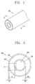
- FIG. 1 is a perspective view of a hollow fiber membrane 100 according to an exemplary embodiment of the present invention
- FIG. 2 is a shape of a cross-section cut along the line AA' of FIG. 1
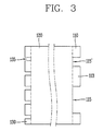
- FIG. 3 is an enlarged view of a portion B of FIG. 2 .
- the hollow fiber membrane 100 according to an exemplary embodiment of the present invention with reference to FIGS. 1 to 3 .
- the hollow fiber membrane 100 according to an exemplary embodiment of the present invention has a cylindrical shape having a hollow part 140 formed therein, and the porosities are different depending on the depth towards the hollow part 140 formed in the inner center.
- FIG. 3 illustrates that the depths of the pores 115 and 115' are all the same as each other, but schematically shows the situation, and in fact, the depths of the pores 115 and 115' are all different from each other. Accordingly, the thickness will be described below, but the rough thickness D1 which may differentiate the first layer 110 needs to be defined. This also applies to the case of a third layer 130. That is, the average thickness D3 of the third layer 130 needs to be defined because the depths of pores 135 in FIG. 3 are all different from each other.
- the porosity of the first layer 110 is set at 30 to 80%.
- the porosity of the first layer 110 is less than 30%, the first layer becomes a dense layer, and thus, the raw water is not smoothly introduced, and when the porosity is more than 80%, the layer may be easily peeled off when the layer is pressurized from the inside or outside, so that the porosity of the first layer 110 is limited to 30 to 80% in an exemplary embodiment of the present invention.
- a high porosity layer may be formed on the first layer 110 to decrease the filtration pressure loss and simultaneously, maintain the high permeability.
- the contaminants are further filtered out while the raw water introduced into the inside of the hollow fiber membrane 100 through the first layer 110 is passing through a second layer 120.
- the second layer 120 is formed on the inside of the first layer 110, and has a porosity of 25 to 65%.
- the porosity of the second layer 120 is less than 25%, the second layer becomes a dense layer, and thus, the raw water does not smoothly pass through and a clogging phenomenon may be generated, and when the porosity is more than 65%, the breaking strength is decreased, and thus, the hollow fiber membrane 100 may be easily broken. This is because it is the state where polymers are not connected to each other.
- the second layer 120 occupies the most part of the hollow fiber membrane 100 and has a thickness D2.
- a third layer 130 called an active layer is formed at the innermost part of the hollow fiber membrane 100.
- the third layer 130 is a layer in which the raw water introduced through the second layer 120 or the raw water introduced from the hollow part 140 passes through, and thus, contaminants in the raw water are filtered out or optionally separated.
- the porosity of the third layer 130 is 25% or less, and the cross-sectional thickness D of the hollow fiber membrane 100 is allowed to occupy 10% or less. That is, a layer having a low porosity of 25% or less may be formed in the third layer 130 to increase the tensile strength and breaking strength of the hollow fiber membrane 100 and maximize the removal performance of a contamination source or maximize the optional permeation performance.
- the size of pores 135 formed on the third layer 130 is smaller than that of macropores 115 formed on the first layer 110.
- the average size of pores 135 formed on the third layer 130 is about 50 nm or less, and preferably, pores having a size of about 20 nm or less may be formed. Accordingly, it is possible to filter out contaminants including viruses having a size of about 20 nm or more.
- the third layer 130 may refer to a layer exhibiting inherent characteristics of the hollow fiber membrane 100.
- the purified water passing through the aforementioned first layer 110 to third layer 130 and introduced into the hollow part 140 may be used as drinking water and the like because most of the contaminants are filtered out.
- the cross-sectional thickness D of the hollow fiber membrane 100 means a distance from the outermost part of the hollow part 140 formed on the inside of the hollow fiber membrane 100 to the surface of the first layer 110 of the hollow fiber membrane 100 exposed to the outside.
- the hollow fiber membrane 100 has a cross-sectional thickness D of 50 to 400 ⁇ m.
- the cross-sectional thickness D is not always limited thereto, and may be adjusted, if necessary.
- the thickness of the third 130 may also vary depending on the change in cross-sectional thickness D of the hollow fiber membrane 100.
- the first layer 110 to the third layer 130 are integrally formed, the porosity of the first layer 110 is formed to be larger than that of the third layer 130, and the porosity of the second layer 120 has a roughly value between the porosities of the first layer 110 and the third layer 130, but the present invention is not always limited thereto. That is, the porosity of the second layer 120 may also be larger than that of the first layer 110.
- a network structure formed of a polymer is present in the first layer 110 to the third layer 130, and the filtration pressure loss is minimized by adjusting the porosity as described above.
- the filtration pressure loss means a difference between a pressure (Pe) acting on the outside of the hollow fiber membrane 100 and a pressure (Pi) at the hollow part 140 of the hollow fiber membrane 100, and the lower filtration pressure loss is, the more sufficiently contaminants may be removed at even a small pressure, so that the filtration efficiency (permeation rate) is excellent.
- the first layer 110 is formed within 20 ⁇ m towards the inside cross-section from the outermost part of the hollow fiber membrane 100 exposed to the outside
- the third layer 130 is formed within 20 ⁇ m towards the outside from the outermost part of the hollow part 140 in a radial direction.
- FIG. 4 is an SEM photograph of a portion B of FIG. 2 , and it can be seen that the thickness D2 of the second layer 120 formed at the middle portion thereof is largest, illustrating that the thickness D1 of the first layer 110 and the thickness D3 of the third layer 130 are similar to each other.
- FIGS. 5 and 6 are enlarged SEM photographs of the outermost layer of FIG. 4 , illustrating a network structure formed on the first layer 110 which is an outermost layer, FIGS. 5 and 6 are photographs taken by varying the magnification, and FIG. 6 is an SEM photograph taken at a higher magnification.
- the porosity is increased by the network structure as described above, thereby decreasing the filtration pressure loss.
- the hollow fiber membrane may be formed of at least one of polysulfone, polyether sulfone, or a polymer using the same.
- the amount of water permeating at the same area in a cross flow manner at 1 bar for a predetermined time was measured by manufacturing a pressurized module.
- the first Example is about the case where the network structure formed on the first layer 110, which is an outermost layer, has a thickness of 15 to 20 ⁇ m
- the second Example is about the case where the network structure formed on the first layer 110 has a thickness of 10 ⁇ m
- the third Example is about the case where the network structure formed on the first layer 100 has a thickness of 3 ⁇ m.
- the water permeability in the first to fourth Examples was shown as 860 L/m 2 ⁇ hr, 550 L/m 2 ⁇ hr, and 35L/m 2 ⁇ hr, respectively.
- the water permeability of the hollow fiber membrane densely formed without a network structure in the first layer 110 under the experimental conditions which are the same as in the first to fourth Examples, the water permeability was shown as 130 L/m 2 ⁇ hr.
- the porosities of the hollow fiber membrane 100 of the present invention are gradually decreased from the first layer to the third layer.
- the water permeability of the hollow fiber membrane structure of the present invention may be improved up to 1,600 L/m 2 ⁇ hr.
- the SEM photograph for the Comparative Example is illustrated in FIG. 7 , and as illustrated in FIG. 7 , it can be seen that when the first layer 11 is densely formed without a network structure, the porosity is decreased, and thus, the water permeability is rapidly decreased compared to the case of the first to third Examples.
- the hollow fiber membrane as described above is not limited by the configurations and methods of the exemplary embodiments as described above, but the exemplary embodiments may also be configured by selectively combining a whole or part of the exemplary embodiments, such that various modifications can be made.
- the exemplary embodiments of the present invention may be applied to a hollow fiber membrane which controls the permeability by controlling the porosity.
Landscapes
- Chemical & Material Sciences (AREA)
- Chemical Kinetics & Catalysis (AREA)
- Engineering & Computer Science (AREA)
- Water Supply & Treatment (AREA)
- Nanotechnology (AREA)
- Separation Using Semi-Permeable Membranes (AREA)
Abstract
Description
- The present invention relates to a hollow fiber membrane, and more particularly, to a hollow fiber membrane whose porosity is different depending on the depth of the cross-section.
- In general, hollow fiber membranes are prepared by using a non-solvent phase separation method or a thermally induced phase separation method. Hollow fiber membranes produced by the aforementioned method are classified into a microfiltration membrane (MF), a ultrafiltration membrane (UF), a nanofiltration membrane (NF), and a reverse osmosis membrane (RO).
- A typical hollow fiber membrane has the outermost layer and the innermost layer, and these parts are responsible for the removal performance of a contamination source as an active layer. Further, the hollow fiber membrane exhibits a difference in permeability depending on the porosity of the hollow fiber membrane, and when the cross-sectional structure of the hollow fiber membrane has a low porosity, the hollow membrane has a low permeability and a high strength, but in contrast, when the structure has a high porosity, the hollow fiber membrane exhibits a high permeability, but shows a low strength.
- Conventional hollow fiber membranes are intended to minimize the filtration pressure loss by increasing the porosity of the cross-section of the hollow fiber membrane in order to increase the permeability, but only result in a reduction in tensile strength and breaking strength of the hollow fiber membrane. In addition, efforts have been made to even remove fine contaminants by decreasing the porosity of the cross-section of the hollow fiber membrane in order to enhance the removal performance of the contaminants, but the filtration pressure loss is increased, so that the permeability rapidly decreases, and the economic loss was enormous in order to utilize this. Various methods have been tried to overcome this, but it has been difficult to increase the water permeability by minimizing the filtration pressure loss, and simultaneously improve the removal rate and the strength.
- Therefore, an object of the present invention is to provide a hollow fiber membrane which increases the breaking strength and the tensile strength and simultaneously improves the permeability by allowing the porosity of the inside cross-section to be different depending on the depth.
- Another object of the present invention is to provide a hollow fiber membrane which may decrease the filtration pressure loss.
- To achieve these and other advantages and in accordance with the purpose of the present invention, as embodied and broadly described herein, there is provided a cylindrical hollow fiber membrane having an inside in which a hollow part is formed along an axial direction, the hollow fiber membrane including: a first layer positioned at the outermost part so as to be exposed to the outside, and having pores formed therein to make raw water enter and leave via the pores; a second layer formed on the inside of the first layer to filter out contaminants from raw water as the raw water passes through; and a third layer to optionally separate or filter out contaminants from the raw water introduced through the second layer or introduced from the hollow part, wherein the first layer to the third layer are integrally formed; the porosity of the first layer is greater than the porosity of the third layer; and porosities are gradually decreased from the first layer to the third layer.
- The first layer may have a porosity of 30 to 80%, and may be formed at a position within 20 µm towards the inside from the outermost part.
- The second layer may have a porosity of 25 to 65%.
- The third layer may have a porosity of 25% or less, may have a thickness which is 10% or less of the thickness of the hollow fiber membrane, and may be formed within 20 µm towards the outside from the outermost part of the hollow part in a radial direction.
- The hollow fiber membrane may be at least one of polysulfone, polyether sulfone, or a polymer using the same.
- The hollow fiber membrane may have a thickness of 50 to 400 µm.
- The first layer to the third layer may have a network structure.
- The third layer has an average pore size of 50 nm or less, or may have an average pore size of 20 nm or less.
- Further, according to an exemplary embodiment of the present invention, provided is a cylindrical hollow fiber membrane having an inside in which a hollow part is formed along an axial direction, the hollow fiber membrane including: a first layer positioned at the outermost part so as to be exposed to the outside, and having pores formed therein to make raw water enter and leave via the pores; a second layer formed on the inside of the first layer to filter out contaminants from raw water as the raw water passes through; and a third layer to optionally separate or filter out contaminants from the raw water introduced through the second layer or introduced from the hollow part, wherein the first layer to the third layer are integrally formed; the first layer is formed at a position within 20 µm towards the inside from the outermost part; and the porosity thereof is 30 to 80%.
- According to an exemplary embodiment of the present invention, the service life of a hollow fiber membrane may be prolonged by minimizing the filtration pressure loss depending on the cross-sectional structure of the hollow fiber membrane, and the removal performance of a contamination source may be maximized or an optional separation performance may be improved while high permeability may be simultaneously expected.
- Furthermore, a high porosity layer may be formed on the cross-section of the outermost part of the hollow fiber membrane to facilitate washing of the membrane, so that stability may be secured even during the long-term operation, and economic efficiency may be enhanced.
-
-
FIG. 1 is a perspective view of a hollow fiber membrane according to an exemplary embodiment of the present invention; -
FIG. 2 is a cross-sectional view along the line AA' ofFIG. 1 ; -
FIG. 3 is a detailed cross-sectional view of a portion B ofFIG. 2 ; -
FIG. 4 is an SEM photograph of a portion B ofFIG. 2 ; -
FIGS. 5 and6 are SEM photographs enlarged by varying the magnification of the outermost layer ofFIG. 4 ; and -
FIG. 7 is an SEM photograph of a hollow fiber membrane according to the Comparative Example. - Reference will now be made in detail to the preferred embodiments of the present invention, examples of which are illustrated in the accompanying drawings. It will also be apparent to those skilled in the art that various modifications and variations can be made in the present invention without departing from the spirit or scope of the invention. Thus, it is intended that the present invention cover modifications and variations of this invention provided they come within the scope of the appended claims and their equivalents.
- Description will now be given in detail of a drain device and a refrigerator having the same according to an embodiment, with reference to the accompanying drawings.
- Hereinafter, a hollow fiber membrane according to an exemplary embodiment of the present invention will be described in more detail with reference to the drawings. In the present specification, like reference numbers are used to designate like constituents even though they are in different exemplary embodiments, and the description thereof will be substituted with the initial description.
- Singular expressions used in the present specification include plural expressions unless they have definitely opposite meanings in the context.
- The present invention has been made in an effort to increase a low strength and decrease the filtration pressure loss, the low strength and the filtration pressure loss being disadvantages which a
hollow fiber membrane 100 has. The present invention increases the breaking strength and simultaneously maximizes the removal performance of contaminants because a layer having a low porosity at the hollow portion inside thehollow fiber membrane 100. Furthermore, the present invention relates to ahollow fiber membrane 100 which decreases the filtration pressure loss and maintains a high permeability by forming a network structure having a high porosity on the cross-section of thehollow fiber membrane 100 except for this. - First,
FIG. 1 is a perspective view of ahollow fiber membrane 100 according to an exemplary embodiment of the present invention,FIG. 2 is a shape of a cross-section cut along the line AA' ofFIG. 1 , andFIG. 3 is an enlarged view of a portion B ofFIG. 2 . - Hereinafter, the
hollow fiber membrane 100 according to an exemplary embodiment of the present invention with reference toFIGS. 1 to 3 . Thehollow fiber membrane 100 according to an exemplary embodiment of the present invention has a cylindrical shape having ahollow part 140 formed therein, and the porosities are different depending on the depth towards thehollow part 140 formed in the inner center. - On a
first layer 110 which is positioned at the outermost part of thehollow fiber membrane 100 and thus is exposed to the outside,macropores 115 and pores 115' smaller than themacropores 115 are formed.FIG. 3 illustrates that the depths of thepores 115 and 115' are all the same as each other, but schematically shows the situation, and in fact, the depths of thepores 115 and 115' are all different from each other. Accordingly, the thickness will be described below, but the rough thickness D1 which may differentiate thefirst layer 110 needs to be defined. This also applies to the case of athird layer 130. That is, the average thickness D3 of thethird layer 130 needs to be defined because the depths ofpores 135 inFIG. 3 are all different from each other. - When a raw water including contaminants is introduced from the outside through the
pores first layer 110 is set at 30 to 80%. When the porosity of thefirst layer 110 is less than 30%, the first layer becomes a dense layer, and thus, the raw water is not smoothly introduced, and when the porosity is more than 80%, the layer may be easily peeled off when the layer is pressurized from the inside or outside, so that the porosity of thefirst layer 110 is limited to 30 to 80% in an exemplary embodiment of the present invention. - That is, a high porosity layer may be formed on the
first layer 110 to decrease the filtration pressure loss and simultaneously, maintain the high permeability. - The contaminants are further filtered out while the raw water introduced into the inside of the
hollow fiber membrane 100 through thefirst layer 110 is passing through asecond layer 120. Thesecond layer 120 is formed on the inside of thefirst layer 110, and has a porosity of 25 to 65%. When the porosity of thesecond layer 120 is less than 25%, the second layer becomes a dense layer, and thus, the raw water does not smoothly pass through and a clogging phenomenon may be generated, and when the porosity is more than 65%, the breaking strength is decreased, and thus, thehollow fiber membrane 100 may be easily broken. This is because it is the state where polymers are not connected to each other. That is, a network structure is formed in thesecond layer 120, and thus minimizes the filtration pressure loss, thereby contributing to the increase and maintenance of the permeation performance. In this case, thesecond layer 120 occupies the most part of thehollow fiber membrane 100 and has a thickness D2. - Furthermore, a
third layer 130 called an active layer is formed at the innermost part of thehollow fiber membrane 100. Thethird layer 130 is a layer in which the raw water introduced through thesecond layer 120 or the raw water introduced from thehollow part 140 passes through, and thus, contaminants in the raw water are filtered out or optionally separated. The porosity of thethird layer 130 is 25% or less, and the cross-sectional thickness D of thehollow fiber membrane 100 is allowed to occupy 10% or less. That is, a layer having a low porosity of 25% or less may be formed in thethird layer 130 to increase the tensile strength and breaking strength of thehollow fiber membrane 100 and maximize the removal performance of a contamination source or maximize the optional permeation performance. In this case, the size ofpores 135 formed on thethird layer 130 is smaller than that ofmacropores 115 formed on thefirst layer 110. In this case, the average size ofpores 135 formed on thethird layer 130 is about 50 nm or less, and preferably, pores having a size of about 20 nm or less may be formed. Accordingly, it is possible to filter out contaminants including viruses having a size of about 20 nm or more. - As described above, the
third layer 130 may refer to a layer exhibiting inherent characteristics of thehollow fiber membrane 100. - The purified water passing through the aforementioned
first layer 110 tothird layer 130 and introduced into thehollow part 140 may be used as drinking water and the like because most of the contaminants are filtered out. - In this case, the cross-sectional thickness D of the
hollow fiber membrane 100 means a distance from the outermost part of thehollow part 140 formed on the inside of thehollow fiber membrane 100 to the surface of thefirst layer 110 of thehollow fiber membrane 100 exposed to the outside. In an exemplary embodiment of the present invention, thehollow fiber membrane 100 has a cross-sectional thickness D of 50 to 400 µm. The cross-sectional thickness D is not always limited thereto, and may be adjusted, if necessary. In addition, it is natural that the thickness of the third 130 may also vary depending on the change in cross-sectional thickness D of thehollow fiber membrane 100. - The
first layer 110 to thethird layer 130 are integrally formed, the porosity of thefirst layer 110 is formed to be larger than that of thethird layer 130, and the porosity of thesecond layer 120 has a roughly value between the porosities of thefirst layer 110 and thethird layer 130, but the present invention is not always limited thereto. That is, the porosity of thesecond layer 120 may also be larger than that of thefirst layer 110. - Further, a network structure formed of a polymer is present in the
first layer 110 to thethird layer 130, and the filtration pressure loss is minimized by adjusting the porosity as described above. In this case, the filtration pressure loss means a difference between a pressure (Pe) acting on the outside of thehollow fiber membrane 100 and a pressure (Pi) at thehollow part 140 of thehollow fiber membrane 100, and the lower filtration pressure loss is, the more sufficiently contaminants may be removed at even a small pressure, so that the filtration efficiency (permeation rate) is excellent. - In this case, the
first layer 110 is formed within 20 µm towards the inside cross-section from the outermost part of thehollow fiber membrane 100 exposed to the outside, and thethird layer 130 is formed within 20 µm towards the outside from the outermost part of thehollow part 140 in a radial direction. -
FIG. 4 is an SEM photograph of a portion B ofFIG. 2 , and it can be seen that the thickness D2 of thesecond layer 120 formed at the middle portion thereof is largest, illustrating that the thickness D1 of thefirst layer 110 and the thickness D3 of thethird layer 130 are similar to each other. -
FIGS. 5 and6 are enlarged SEM photographs of the outermost layer ofFIG. 4 , illustrating a network structure formed on thefirst layer 110 which is an outermost layer,FIGS. 5 and6 are photographs taken by varying the magnification, andFIG. 6 is an SEM photograph taken at a higher magnification. The porosity is increased by the network structure as described above, thereby decreasing the filtration pressure loss. - Furthermore, the hollow fiber membrane may be formed of at least one of polysulfone, polyether sulfone, or a polymer using the same.
- Hereinafter, exemplary embodiments in which the water permeability for the aforementioned
hollow fiber membrane 100 was measured will be described. - For the measurement of water permeability, the amount of water permeating at the same area in a cross flow manner at 1 bar for a predetermined time was measured by manufacturing a pressurized module.
- The first Example is about the case where the network structure formed on the
first layer 110, which is an outermost layer, has a thickness of 15 to 20 µm, the second Example is about the case where the network structure formed on thefirst layer 110 has a thickness of 10 µm, and the third Example is about the case where the network structure formed on thefirst layer 100 has a thickness of 3 µm. - The water permeability in the first to fourth Examples was shown as 860 L/m2·hr, 550 L/m2·hr, and 35L/m2·hr, respectively.
- Meanwhile, in the case of the Comparative Example in which the water permeability of the hollow fiber membrane densely formed without a network structure in the
first layer 110 under the experimental conditions which are the same as in the first to fourth Examples, the water permeability was shown as 130 L/m2·hr. - From the Examples and the Comparative Example, it can be confirmed that the larger the thickness of the network structure formed on the
first layer 110 is, the higher the water permeability is, and it was confirmed that when the hollow fiber membrane has a dense layer without a network structure, the water permeability was lower than the aforementioned water permeability. - As described above, the porosities of the
hollow fiber membrane 100 of the present invention are gradually decreased from the first layer to the third layer. The water permeability of the hollow fiber membrane structure of the present invention may be improved up to 1,600 L/m2·hr. - The SEM photograph for the Comparative Example is illustrated in
FIG. 7 , and as illustrated inFIG. 7 , it can be seen that when the first layer 11 is densely formed without a network structure, the porosity is decreased, and thus, the water permeability is rapidly decreased compared to the case of the first to third Examples. - The hollow fiber membrane as described above is not limited by the configurations and methods of the exemplary embodiments as described above, but the exemplary embodiments may also be configured by selectively combining a whole or part of the exemplary embodiments, such that various modifications can be made.
- Further, it will be understood by those skilled in the art to which the present invention pertains that the present invention can be implemented in other concrete forms without modifying the technical spirit or essential features of the present invention.
- Therefore, the exemplary embodiments described above should be understood as illustrative rather than limiting in all respects. The scope of the present invention is represented by the claims to be described below rather than the detailed description, and it is to be interpreted that the meaning and scope of the claims and all the changes or modified forms derived from the equivalent concepts thereof fall within the scope of the present invention.
- The exemplary embodiments of the present invention may be applied to a hollow fiber membrane which controls the permeability by controlling the porosity.
Claims (20)
- A cylindrical hollow fiber membrane having an inside in which a hollow part is formed along an axial direction, the hollow fiber membrane comprising:a first layer positioned at the outermost part so as to be exposed to an outside, and having pores formed therein to make raw water enter and leave via the pores;a second layer formed on the inside of the first layer to filter out contaminants from the raw water as the raw water passes through; anda third layer to optionally separate or filter out contaminants from the raw water introduced through the second layer or introduced from the hollow part,wherein the first layer to the third layer are integrally formed; a porosity of the first layer is greater than a porosity of the third layer; and porosities are gradually decreased from the first layer to the third layer.
- The hollow fiber membrane of claim 1, wherein the first layer has a porosity of 30 to 80%.
- The hollow fiber membrane of claim 2, wherein the first layer is formed at a position within 20 µm towards the inside from the outermost part.
- The hollow fiber membrane of claim 1, wherein the second layer has a porosity of 25 to 65%.
- The hollow fiber membrane of claim 3, wherein the third layer has a porosity of 25% or less.
- The hollow fiber membrane of claim 5, wherein the third layer has a thickness which is 10% or less of the thickness of the hollow fiber membrane.
- The hollow fiber membrane of claim 6, wherein the third layer is formed within 20 µm towards the outside from the outermost part of the hollow part in a radial direction.
- The hollow fiber membrane of claim 1, wherein the hollow fiber membrane is at least one of polysulfone, polyether sulfone, or a polymer using the same.
- The hollow fiber membrane of claim 1, wherein the hollow fiber membrane has a thickness of 50 to 400 µm.
- The hollow fiber membrane of claim 1, wherein the first layer to the third layer have a network structure.
- The hollow fiber membrane of claim 1, wherein the third layer has an average pore size of 50 nm or less.
- The hollow fiber membrane of claim 11, wherein the third layer has an average pore size of 20 nm or less.
- A cylindrical hollow fiber membrane having an inside in which a hollow part is formed along an axial direction, the hollow fiber membrane comprising:a first layer positioned at the outermost part so as to be exposed to the outside, and having pores formed therein to make raw water enter and leave via the pores;a second layer formed on the inside of the first layer to filter out contaminants from the raw water as the raw water passes through; anda third layer to optionally separate or filter out contaminants from the raw water introduced through the second layer or introduced from the hollow part,wherein the first layer to the third layer are integrally formed; the first layer is formed at a position within 20 µm towards the inside from the outermost part; and a porosity thereof is 30 to 80%.
- The hollow fiber membrane of claim 13, wherein the second layer has a porosity of 25 to 65%.
- The hollow fiber membrane of claim 13, wherein the third layer has a porosity of 25% or less.
- The hollow fiber membrane of claim 15, wherein the third layer has a thickness which is 10% or less of the thickness of the hollow fiber membrane.
- The hollow fiber membrane of claim 16, wherein the third layer is formed within 20 µm towards the outside from the outermost part of the hollow part in a radial direction.
- The hollow fiber membrane of claim 13, wherein the hollow fiber membrane is at least one of polysulfone, polyether sulfone, or a polymer using the same.
- The hollow fiber membrane of claim 13, wherein the hollow fiber membrane has a thickness of 50 to 400 µm.
- The hollow fiber membrane of claim 13, wherein the first layer to the third layer have a network structure.
Applications Claiming Priority (2)
| Application Number | Priority Date | Filing Date | Title |
|---|---|---|---|
| KR1020130160586A KR102140264B1 (en) | 2013-12-20 | 2013-12-20 | Hollow fiber membrane |
| PCT/KR2014/006719 WO2015093705A1 (en) | 2013-12-20 | 2014-07-23 | Hollow fiber membrane |
Publications (2)
| Publication Number | Publication Date |
|---|---|
| EP3085433A1 true EP3085433A1 (en) | 2016-10-26 |
| EP3085433A4 EP3085433A4 (en) | 2017-08-23 |
Family
ID=53403025
Family Applications (1)
| Application Number | Title | Priority Date | Filing Date |
|---|---|---|---|
| EP14870848.0A Withdrawn EP3085433A4 (en) | 2013-12-20 | 2014-07-23 | Hollow fiber membrane |
Country Status (7)
| Country | Link |
|---|---|
| US (1) | US10596524B2 (en) |
| EP (1) | EP3085433A4 (en) |
| JP (1) | JP6273014B2 (en) |
| KR (1) | KR102140264B1 (en) |
| CN (1) | CN105828920B (en) |
| AU (1) | AU2014367656A1 (en) |
| WO (1) | WO2015093705A1 (en) |
Families Citing this family (5)
| Publication number | Priority date | Publication date | Assignee | Title |
|---|---|---|---|---|
| WO2017155034A1 (en) * | 2016-03-11 | 2017-09-14 | 旭化成株式会社 | Porous membrane, porous membrane module, porous membrane manufacturing method, manufacturing method for clarified liquids, and manufacturing method for beer |
| KR102017195B1 (en) * | 2016-11-11 | 2019-09-02 | 주식회사 엘지화학 | Hollow fiber membrane |
| CN109133267B (en) * | 2018-09-06 | 2021-11-12 | 偶极医药科技(徐州)有限公司 | Electrodialysis device for purifying phenylalanine |
| CN115382397B (en) * | 2022-08-22 | 2024-07-02 | 国能龙源环保南京有限公司 | Hollow fiber membrane modules and methods of use |
| CN115259331B (en) * | 2022-08-26 | 2023-09-08 | 中国科学院生态环境研究中心 | Membrane contact reactor and treatment system for wastewater deamination |
Family Cites Families (22)
| Publication number | Priority date | Publication date | Assignee | Title |
|---|---|---|---|---|
| US4629563B1 (en) | 1980-03-14 | 1997-06-03 | Memtec North America | Asymmetric membranes |
| JPS61200805A (en) | 1985-03-01 | 1986-09-05 | Teijin Ltd | Polyether sulfone microporous hollow yarn membrane and its production |
| JP2736992B2 (en) * | 1989-03-22 | 1998-04-08 | 旭化成工業株式会社 | Polysulfone hollow fiber membrane and method for producing the same |
| NL1004210C2 (en) | 1996-10-07 | 1998-04-10 | Prime Water Systems N V | Water filtration device. |
| KR100575113B1 (en) * | 2000-06-21 | 2006-05-03 | 가부시키가이샤 구라레 | Porous hollow fiber membranes and method of making the same |
| WO2003026779A1 (en) | 2001-08-01 | 2003-04-03 | Asahi Kasei Kabushiki Kaisha | Multilayer microporous film |
| US6663805B1 (en) * | 2002-09-20 | 2003-12-16 | L'air Liquide Societe Anonyme A Directoire Et Conseil De Surveillance Pour L'etude Et L'exploitation Des Procedes Georges Claude | Process for making hollow fiber mixed matrix membranes |
| BRPI0508601A (en) * | 2004-03-17 | 2007-07-31 | Bussan Nanotech Res Inst Inc | separation membrane |
| AU2005295757A1 (en) * | 2004-10-15 | 2006-04-27 | 3M Innovative Properties Company | Pleated multi-layer filter media and cartridge |
| JP2009504399A (en) | 2005-08-22 | 2009-02-05 | シーメンス・ウォーター・テクノロジーズ・コーポレーション | Assembly for water filtration using a tubular manifold to minimize backwash |
| JP5433921B2 (en) | 2006-04-26 | 2014-03-05 | 東洋紡株式会社 | Polymer porous hollow fiber membrane |
| EP2024068B1 (en) | 2006-05-06 | 2012-01-18 | Membrana GmbH | Ultrafiltration membrane |
| US8596467B2 (en) | 2006-10-18 | 2013-12-03 | Gambro Lundia Ab | Hollow fiber membrane and method for manufacturing thereof |
| KR100861078B1 (en) * | 2007-01-29 | 2008-09-30 | 정덕수 | Asymmetric multilayer ceramic filter and its manufacturing method and water purification system using the same |
| JP5504560B2 (en) | 2007-10-19 | 2014-05-28 | 東洋紡株式会社 | Hollow fiber membrane for liquid processing |
| EP2468389B1 (en) * | 2009-08-21 | 2020-10-21 | Toray Industries, Inc. | Water-vapor-permeable membrane, hollow-fiber membrane, and hollow-fiber membrane module |
| JP5212837B2 (en) | 2009-10-08 | 2013-06-19 | 東洋紡株式会社 | Permselective hollow fiber membrane |
| EP2548632A4 (en) | 2010-03-04 | 2017-03-15 | Sekisui Chemical Co., Ltd. | Macromolecular water-treatment membrane, manufacturing method therefor, and water treatment method |
| SG183782A1 (en) * | 2010-04-16 | 2012-11-29 | Asahi Kasei Chemicals Corp | Deformed porous hollow fiber membrane, production method of deformed porous hollow fiber membrane, and module, filtration device, and water treatment method in which deformed porous hollow fiber membrane is used |
| CN105413480B (en) | 2011-04-01 | 2019-03-29 | Emd密理博公司 | Composite structure containing nanofiber |
| SG188680A1 (en) | 2011-09-14 | 2013-04-30 | Univ Singapore | Thin film composite nanofiltration hollow fiber membranes |
| US9352267B2 (en) * | 2012-06-20 | 2016-05-31 | Hollingsworth & Vose Company | Absorbent and/or adsorptive filter media |
-
2013
- 2013-12-20 KR KR1020130160586A patent/KR102140264B1/en active Active
-
2014
- 2014-07-23 WO PCT/KR2014/006719 patent/WO2015093705A1/en not_active Ceased
- 2014-07-23 CN CN201480068987.9A patent/CN105828920B/en active Active
- 2014-07-23 AU AU2014367656A patent/AU2014367656A1/en not_active Abandoned
- 2014-07-23 EP EP14870848.0A patent/EP3085433A4/en not_active Withdrawn
- 2014-07-23 US US15/038,931 patent/US10596524B2/en active Active
- 2014-07-23 JP JP2016535685A patent/JP6273014B2/en active Active
Also Published As
| Publication number | Publication date |
|---|---|
| EP3085433A4 (en) | 2017-08-23 |
| JP2016540635A (en) | 2016-12-28 |
| KR102140264B1 (en) | 2020-07-31 |
| CN105828920A (en) | 2016-08-03 |
| AU2014367656A1 (en) | 2016-06-16 |
| KR20150072913A (en) | 2015-06-30 |
| JP6273014B2 (en) | 2018-01-31 |
| US10596524B2 (en) | 2020-03-24 |
| WO2015093705A1 (en) | 2015-06-25 |
| CN105828920B (en) | 2018-07-10 |
| US20170001152A1 (en) | 2017-01-05 |
Similar Documents
| Publication | Publication Date | Title |
|---|---|---|
| US10596524B2 (en) | Hollow fiber membrane | |
| KR100909528B1 (en) | Separator, Separator Member, Separator Module, Sewage Treatment System and Manufacturing Method of Separator | |
| KR101372056B1 (en) | Porous vinylidene fluoride resin membrane and process for producing same | |
| JP2017047417A (en) | Separation membrane module, separation membrane element and telescope prevention plate | |
| KR20130054231A (en) | Separation membrane and method for producing same | |
| US20170001884A1 (en) | Filtration element | |
| JP6374291B2 (en) | Hollow fiber membrane module | |
| CN109496163B (en) | Separation membrane element | |
| US11944939B2 (en) | Hollow fiber membrane element, hollow fiber membrane module, and method of forward osmosis water treatment | |
| KR20170042560A (en) | Reverse osmosis membrane device and method for operating same | |
| US11471834B2 (en) | Filtration method using porous membrane | |
| KR101025755B1 (en) | Ultrafiltration Membrane with Improved Permeability and Mechanical Strength and Manufacturing Method Thereof | |
| KR102017195B1 (en) | Hollow fiber membrane | |
| JP5315626B2 (en) | Method for producing nonwoven fabric for separation membrane | |
| US20220001335A1 (en) | Method of filtration using porous membranes | |
| JP6637232B2 (en) | Permeation-side flow path material for spiral-type membrane element and method for producing the same | |
| JP5023430B2 (en) | Hollow fiber membrane module and manufacturing method thereof | |
| WO2017122673A1 (en) | Hollow fiber semipermeable membrane for reverse osmosis or forward osmosis | |
| EP3608012A1 (en) | Feed spacer and reverse osmosis filter module including same | |
| JPWO2016182015A1 (en) | Porous hollow fiber membrane and method for producing the same | |
| CN217746520U (en) | Microfiltration membrane with degerming separation function | |
| CN222446036U (en) | Composite membrane and water treatment device | |
| KR101364862B1 (en) | Porous PVDF hollow fiber membrane | |
| EP4450149A3 (en) | Dry-process membrane for filtration | |
| JPWO2024185562A5 (en) |
Legal Events
| Date | Code | Title | Description |
|---|---|---|---|
| PUAI | Public reference made under article 153(3) epc to a published international application that has entered the european phase |
Free format text: ORIGINAL CODE: 0009012 |
|
| 17P | Request for examination filed |
Effective date: 20160531 |
|
| AK | Designated contracting states |
Kind code of ref document: A1 Designated state(s): AL AT BE BG CH CY CZ DE DK EE ES FI FR GB GR HR HU IE IS IT LI LT LU LV MC MK MT NL NO PL PT RO RS SE SI SK SM TR |
|
| AX | Request for extension of the european patent |
Extension state: BA ME |
|
| DAX | Request for extension of the european patent (deleted) | ||
| A4 | Supplementary search report drawn up and despatched |
Effective date: 20170725 |
|
| RIC1 | Information provided on ipc code assigned before grant |
Ipc: B01D 71/68 20060101ALI20170717BHEP Ipc: B01D 69/08 20060101AFI20170717BHEP Ipc: B01D 69/02 20060101ALI20170717BHEP Ipc: B01D 69/12 20060101ALI20170717BHEP |
|
| RAP1 | Party data changed (applicant data changed or rights of an application transferred) |
Owner name: LG CHEM, LTD. |
|
| STAA | Information on the status of an ep patent application or granted ep patent |
Free format text: STATUS: EXAMINATION IS IN PROGRESS |
|
| 17Q | First examination report despatched |
Effective date: 20190130 |
|
| STAA | Information on the status of an ep patent application or granted ep patent |
Free format text: STATUS: THE APPLICATION IS DEEMED TO BE WITHDRAWN |
|
| 18D | Application deemed to be withdrawn |
Effective date: 20210831 |