EP3085265A1 - Clasp for bracelet - Google Patents
Clasp for bracelet Download PDFInfo
- Publication number
- EP3085265A1 EP3085265A1 EP15164867.2A EP15164867A EP3085265A1 EP 3085265 A1 EP3085265 A1 EP 3085265A1 EP 15164867 A EP15164867 A EP 15164867A EP 3085265 A1 EP3085265 A1 EP 3085265A1
- Authority
- EP
- European Patent Office
- Prior art keywords
- blade
- base plate
- strand
- bracelet
- cover
- Prior art date
- Legal status (The legal status is an assumption and is not a legal conclusion. Google has not performed a legal analysis and makes no representation as to the accuracy of the status listed.)
- Granted
Links
Images


Classifications
-
- A—HUMAN NECESSITIES
- A44—HABERDASHERY; JEWELLERY
- A44C—PERSONAL ADORNMENTS, e.g. JEWELLERY; COINS
- A44C5/00—Bracelets; Wrist-watch straps; Fastenings for bracelets or wrist-watch straps
- A44C5/18—Fasteners for straps, chains or the like
- A44C5/22—Fasteners for straps, chains or the like for closed straps
- A44C5/24—Fasteners for straps, chains or the like for closed straps with folding devices
-
- A—HUMAN NECESSITIES
- A44—HABERDASHERY; JEWELLERY
- A44C—PERSONAL ADORNMENTS, e.g. JEWELLERY; COINS
- A44C5/00—Bracelets; Wrist-watch straps; Fastenings for bracelets or wrist-watch straps
- A44C5/14—Bracelets; Wrist-watch straps; Fastenings for bracelets or wrist-watch straps characterised by the way of fastening to a wrist-watch or the like
-
- A—HUMAN NECESSITIES
- A44—HABERDASHERY; JEWELLERY
- A44C—PERSONAL ADORNMENTS, e.g. JEWELLERY; COINS
- A44C5/00—Bracelets; Wrist-watch straps; Fastenings for bracelets or wrist-watch straps
- A44C5/18—Fasteners for straps, chains or the like
- A44C5/22—Fasteners for straps, chains or the like for closed straps
- A44C5/24—Fasteners for straps, chains or the like for closed straps with folding devices
- A44C5/243—Automatic folding spring closure
-
- A—HUMAN NECESSITIES
- A44—HABERDASHERY; JEWELLERY
- A44C—PERSONAL ADORNMENTS, e.g. JEWELLERY; COINS
- A44C5/00—Bracelets; Wrist-watch straps; Fastenings for bracelets or wrist-watch straps
- A44C5/18—Fasteners for straps, chains or the like
- A44C5/22—Fasteners for straps, chains or the like for closed straps
- A44C5/24—Fasteners for straps, chains or the like for closed straps with folding devices
- A44C5/246—Fasteners for straps, chains or the like for closed straps with folding devices having size adjusting means
-
- A—HUMAN NECESSITIES
- A44—HABERDASHERY; JEWELLERY
- A44B—BUTTONS, PINS, BUCKLES, SLIDE FASTENERS, OR THE LIKE
- A44B11/00—Buckles; Similar fasteners for interconnecting straps or the like, e.g. for safety belts
- A44B11/20—Buckles; Similar fasteners for interconnecting straps or the like, e.g. for safety belts engaging holes or the like in strap
- A44B11/22—Buckle with fixed prong
- A44B11/226—Buckle with fixed prong with cover plate
-
- A—HUMAN NECESSITIES
- A44—HABERDASHERY; JEWELLERY
- A44D—INDEXING SCHEME RELATING TO BUTTONS, PINS, BUCKLES OR SLIDE FASTENERS, AND TO JEWELLERY, BRACELETS OR OTHER PERSONAL ADORNMENTS
- A44D2200/00—General types of fasteners
- A44D2200/10—Details of construction
Definitions
- the invention relates to a clasp for an adjustable strand bracelet, and in particular for watch bracelets.
- a bracelet clasp having a mechanism comprising a base plate hinged to the end of a blade, and an inverted U-shaped cowl protruding from the base plate and the two free edges of which are respectively extended by the same side by a side arm whose end is rotatably mounted to the corresponding side face of the base plate.
- the free edges of the cover can be locked by means of lateral locking means, the adjustable strand passing between the base plate and the cover, and being held by a protruding nipple of the inner face of the base plate or cover.
- the invention particularly aims to overcome the various disadvantages of these known techniques.
- an object of the invention is to provide a clasp for a simple and quick adjustment of the length of a bracelet strand.
- the invention also aims, at least in a particular embodiment, to provide a clasp that is simple to implement and inexpensive.
- a clasp for a bracelet comprising at least first and second blades, the first blade being articulated to the second blade by a first end, between a closed position, said bearing position, in which the first blade is folded over the second blade, and an open position in which the first blade is disengaged from the second blade, the second blade carrying at a second end a fastener of a first bracelet strand, a second bracelet strand being connected at least indirectly to the second blade, the first blade having first locking means capable of holding the first blade in its closed position,
- the second locking means comprise a pusher arranged to be moved in a longitudinal direction of the bracelet, in response to an action by the user, between a first rest position in which the base plate is locked in the closed position. on the second blade, and a second pushed position in which base plate is disengaged from the second blade.
- the invention also relates to a clasp for a bracelet, of the unfolding clasp type, comprising at least first and second blades, the first blade being articulated to the second blade by a first end, between a closed position, called the wearing position, in which the first blade is folded over the second blade, and an open position in which the first blade is disengaged from the second blade, the first blade carrying at a second end a fastener of a first strand of a bracelet, a second strand bracelet being connected at least indirectly to the second blade, the first blade having first locking means adapted to maintain the first blade in its closed position.
- the second locking means comprise a pusher arranged to be moved in a longitudinal direction of the bracelet, in response to an action by the user, between a first rest position in which the hood is locked in the closed position on the base plate, and a second pushed position in which the hood is clear of the base plate.
- the second locking means comprising a pusher arranged to be moved in a longitudinal direction of the bracelet, in response to an action by the user, between a first rest position in which the cover is locked in the closed position on the base plate, and a second pushed position in which the hood is clear of the base plate.
- the object of the present invention by its different functional and structural aspects described above, provides a clasp whose adjustment of the length of a strand is particularly easy and fast.
- the invention relates to a clasp for a bracelet, of the folding clasp type, comprising at least first and second blades, the first blade 1 being articulated to the second blade 2 by a first end, between a position closed, said bearing position, in which the first blade 1 is folded over the second blade 2, and an open position in which the first blade 1 is disengaged from the second blade 2.
- the first blade 1 carries at a second end a fastener 20 of a first strand 100 of a bracelet, a second strap strand 101 being connected at least indirectly to the second blade 2 by means of a fastening link 11 by for example, the first blade 1 having first locking means capable of holding the first blade 1 in its closed position.
- the strands 100, 101 may be made of materials such as leather, fabric, canvas, or any other material known to those skilled in the art for making bracelets or belts.
- the first locking means may be formed, for example, by at least one trigger 32 configured to maintain and / or release a pin, said lower pin 31, so as to maintain the first blade 1 in its closed position against the second blade 2 or release the first blade 1 in its unobstructed position.
- the second blade 2 may, for example, have a through hole at its center, said central orifice 25, the central orifice being configured to receive the lower pin 31 so that the lower pin 31 cooperates with the trigger.
- other locking means could have been envisaged by the skilled person in the context of the present invention.
- the base plate 21 and the cover 22 allows the first strand 100 to pass between the base plate 21 and the cover 22.
- the first strand 100 passes through the adjustment means, at the level of the articulation of the hood on the base plate.
- the first strand 100 is held in its position by means of holding means such as a pin, said upper nipple 30, intended to be inserted into a suitable hole of the first strand 100 for define an anchor point of the latter at the clasp.
- holding means such as a pin, said upper nipple 30, intended to be inserted into a suitable hole of the first strand 100 for define an anchor point of the latter at the clasp.
- other holding means could have been envisaged by those skilled in the art in the context of the present invention.
- the adjustment means also comprise second locking means for holding the cover 22 in the closed position on the base plate 21.
- the second locking means are formed by a pusher 24 arranged to be displaced in a longitudinal direction of the first strand 100, in response to an action by the user, between a first rest position in which the cover 22 is locked in the closed position on the base plate 21, and a second pushed position in which the cover 22 is disengaged from the base plate 21.
- the second locking means comprise return means, such as springs 230, configured to exert a force on the pusher 24 so as to maintain the pusher 24 in the closed position.
- the base plate 21 comprises guide means for the pusher 24 and the springs 230, the guide means being respectively in the form of a guide slot 210 on either side of the base plate 21 for the pusher 24 and a guide cylinder 211 for each spring 230, the springs 230 thus being held laterally in the guide cylinders 211.
- the guide slots 210 are provided open, so that the pusher 24 can cooperate with the side walls of the cover 21.
- the pusher 24 is formed by a body 240, of width equivalent to the width of the base plate 21, and has an arm 241 disposed at each of its ends, the arms 241 being configured to slide within the guide slots 210 and cooperating in support with the springs 230.
- each arm 241 of the pusher 24 comprises a pin 241 directed towards the outside of the guide slot 210 to cooperate with one of the side walls 220 of the hood 22.
- the pusher also has a through hole 243 at each arm 241, each of the through holes 243 being configured to pass a screw 212 attached to the base plate 21 and thereby hold the pusher 24 in place while being constrained by the springs 230.
- the holes Through-holes 243 are larger in diameter than those of the screws 212, the difference between the diameters of the hole 243 and the screw 212 defining the stroke length of the pusher 24.
- the cover 22 has an L-shaped groove 221 on the internal face of each of its side walls 220, preferably disposed near one of its ends, each L-shaped groove 221 being configured to cooperate with a pion 241 respective pusher 24.
- the cover 22 comprises on the inner face of each of its side walls 220 a pin, and each arm 241 of the pusher 24 comprises a groove configured to cooperate with a respective pin of the cover 22
- the grooves move and release the pins present on the side walls 220 of the cover 22.
- the springs 230 force the pusher 24 so that the body 240 of the pusher 24 protrudes slightly from the cover 22 and the pins 241 remain in place at the bottom of the grooves L 221.
- the user presses the pusher 24 so as to place the pegs 241 in abutment with the foot of the L of each L-shaped groove 221. The user can then raise the cover 22 and release the first strand 100 by lifting the latter in order to extract the upper nipple of the first strand 100.
- the user can use the same finger to press the pusher 24 and lift the cover 22, the finger arriving in the immediate vicinity of the cover 22 once the pusher in the pushed position.
- the clasp for a bracelet comprises first, second and third blades, the first blade 1 being articulated to the second blade 2 at one end, and the third blade 3 being hinged to the second blade 2 by the second end opposite the first end.
- the first blade 1 and the third blade 3 can pass from a closed position, called the wearing position, in which the first blade 1 and the third blade 3 are folded over the second blade 2, and an open position in which the first blade 1 and the third blade 3 are disengaged from the second blade 2.
- the first blade 1 carries at its second end a fastener 20 of a first strand 100 of a bracelet, a second strap strand 101 being connected at least indirectly to the second blade 2, the first blade 1 having first locking means 10 able to maintain the first blade 1 in its closed position.
- the fastener 20 comprises means for adjusting the length of the first strand 100 identical to those present in the first embodiment, therefore we do not go back to the description of these adjustment means.
- the second blade 2 comprises two longitudinal recesses 26 and 27 arranged symmetrically on either side of the central orifice 25.
- the longitudinal recesses 26 and 27 are respectively of complementary shape to the first blade 1 and the third blade 3 .
- first blade 1 and the third blade 3 rest at least partially in the longitudinal housing 26 and 27, so that the second end of the first blade 1 and the third blade 3 rests on the second blade 2 in the immediate vicinity of the central orifice 25.
- the base plate 21 has a recess 213 at the end receiving the pusher 24 so as to form a housing, between the base plate 21 and the pusher 24, which is configured to receive the second end of the third blade 3 when the first blade 1 and the third blade 3 are in the closed position.
- the fixing member 20 has a receptacle 200 in which the body 240 of the pusher 24 is housed when the first blade 1 and the third blade 3 are folded on the second blade 2 in closed position.
- the user folds at first the third blade 3 on the second blade 2 in the corresponding longitudinal recess 27, so that the second end of the third blade 3 is positioned above the orifice central 25. Then, the user folds the first blade 1 on the second blade 2 in the corresponding longitudinal recess 26, so that the second end of the first blade 1 is positioned above the central orifice 25 and that the second end of the third blade 3 rests at the hollow 213. Finally, the blades 1 and 3 are locked once the user positions the lower pin 31 in the central hole 25 so as to lock it through first locking means.
- the clasp comprises a first blade 1 articulated to a second blade 2 at a first end, between a closed position, called the wearing position, in which the first blade 1 is folded over the second blade 2, and an open position in which the first blade 1 is disengaged from the second blade 2.
- the second blade 2 carries at a second end a fastener 20 of a first strand 100 of a bracelet, a second strand of bracelet that can be connected at least indirectly to the first blade 1 by means of a rod 13 for example, the first blade 1 having first locking means adapted to maintain the first blade 1 in its closed position.
- the second blade comprises at its second end a bridge 40 for the passage of the first strand 100.
- the bridge 40 may be perforated according to the material used to manufacture the clasp blades, so as to reduce manufacturing costs.
- the first locking means may be formed, for example, by at least one trigger 32 configured to maintain and / or release a pin, said upper pin 30 'on the second blade 2, so as to maintain the first blade 1 in its position closed against the second blade 2 or release the first blade 1 in its disengaged position.
- the first blade 1 comprises a guide element 12 which makes it possible to guide the first blade 1 laterally relative to the second blade 2 when the first blade 1 is folded over the second blade 2.
- Another advantage of this Guiding element 12 is to prevent the first blade 1 to be moved laterally and thus prevent wear or even breakage of the upper pin 30 'when the clasp is closed.
- the fixing member 20 comprises means for adjusting the useful length of the bracelet, these adjustment means comprising a base plate 21 pivotally articulated at the second end of the second blade 2, the base plate being held by a bar 10
- the base plate 21 and the second blade 2 allows the first strand 100 to pass under the base plate 21 by the bridge 40 of the second blade 2.
- the first strand 100 passes through the means of adjustment, at the articulation of the base plate 21
- the first strand 100 is held in its position by means of holding means such as a nipple, said lower nipple 31 ', intended to be inserted into a suitable hole of the first strand 100 to define an anchor point of the latter to the clasp.
- holding means such as a nipple, said lower nipple 31 ', intended to be inserted into a suitable hole of the first strand 100 to define an anchor point of the latter to the clasp.
- other holding means could have been envisaged by those skilled in the art in the context of the present invention.
- the adjustment means also comprise second locking means for holding the base plate 21 in the closed position on the second blade 2.
- the second locking means are formed by a pusher 24 arranged to be moved in a longitudinal direction of the first strand 100, in response to an action by the user, between a first rest position in which the base plate 21 is locked in the closed position on the second blade 2, and a second pushed position in which the base plate 21 is disengaged from the second blade 2.
- the second locking means comprise return means, such as springs 230, configured to exert a force on the pusher 24 so as to maintain the pusher 24 in the closed position.
- the base plate 21 comprises guide means for the pusher 24 and the springs 230, the guide means being respectively in the form of a guide slot 210 on either side of the base plate 21 for the pusher 24 and a guide cylinder 211 for each spring 230, the springs 230 thus being held laterally in the guide cylinder 211.
- the pusher 24 is formed by a body 240, of width equivalent to the width of the base plate 21, and has an arm 241 disposed at each of its ends, the arms 241 being configured to slide within the guide slots 210 and cooperating in support with the springs 230.
- each arm 241 of the pusher 24 comprises an L-shaped groove 221 facing outwards to cooperate with one of the side walls 41, 42 of the bridge 40 of the second blade 2.
- the bridge 40 has a pin 242 on the inner face of each of its side walls 41, 42, preferably disposed near one of its ends, each pin 242 being configured to cooperate with a groove L 221 respective pusher 24.
- the skilled person can reverse the position of the pins 242 and grooves L 221.
- the pins 242 can be located on the pusher 24 and the grooves L 221 on the side walls 41 and 42 of the bridge 40 .
- the springs 230 force the pusher 24 so that the pins 241 of the bridge 40 remain in place at the bottom of the L-grooves 221 of the base plate 21.
- base 21 the user presses the pusher 24 so as to place the pins 241 in abutment at the foot of the L of each groove L 221. The user can then lift the base plate 21 and release the first strand 100 in lifting the latter so as to extract the nipple of the first strand 100.
- the invention also relates to a wristwatch comprising a bracelet provided with a clasp as described above.
- the second locking means comprise a pusher 24 arranged to be moved in a longitudinal direction of the strand, in response to an action by the user, between a first rest position in which the cover 22 is locked in position. closed on the base plate 21, and a second pushed position in which the cover 22 is disengaged from the base plate 21.
Abstract
L'invention se rapporte à un fermoir pour bracelet comprenant un organe de fixation muni de moyens de réglage de la longueur utile du bracelet, ces moyens de réglage comprenant : - une plaque de base assujettie et articulée en pivotement à la seconde extrémité de la deuxième lame, le premier brin passant entre la plaque de base et la deuxième lame et étant maintenu par le biais de moyens de maintien, - des seconds moyens de verrouillage en position fermée de la plaque de base sur la deuxième lame, Selon l'invention, les seconds moyens de verrouillage comprennent un poussoir agencé pour être déplacé entre une première position de repos dans laquelle plaque de base est verrouillée en position fermée sur la deuxième lame, et une seconde position poussée dans laquelle plaque de base est dégagée de la deuxième lame.The invention relates to a clasp for a bracelet comprising a fixing member provided with means for adjusting the useful length of the bracelet, these adjustment means comprising: a base plate secured and pivotally articulated at the second end of the second blade, the first wire passing between the base plate and the second blade and being held by means of holding means, - Second locking means in the closed position of the base plate on the second blade, according to the invention, the second locking means comprise a pusher arranged to be moved between a first rest position in which the base plate is locked in closed position on the second blade, and a second pushed position in which base plate is disengaged from the second blade.
Description
L'invention se rapporte à un fermoir pour bracelet à brin réglable, et notamment pour des bracelets de montres.The invention relates to a clasp for an adjustable strand bracelet, and in particular for watch bracelets.
Il est connu du document
La manipulation d'un tel mécanisme n'est pas aisée pour un utilisateur car il est nécessaire de déverrouiller le mécanisme au moyen d'un ongle pour pouvoir régler la longueur du brin, et de maintenir la plaque de base lorsque l'on veut changer la longueur du brin du bracelet. De plus, le verrouillage du mécanisme n'est pas totalement sûr, le capot pouvant se déverrouiller dans le cas d'un accrochage ou d'un choc lorsque le bracelet est porté.The manipulation of such a mechanism is not easy for a user because it is necessary to unlock the mechanism by means of a fingernail to adjust the length of the strand, and maintain the base plate when you want to change the length of the strand of the bracelet. In addition, the locking mechanism is not completely safe, the hood can be unlocked in the case of a collision or shock when the bracelet is worn.
L'invention a notamment pour objectif de pallier les différents inconvénients de ces techniques connues.The invention particularly aims to overcome the various disadvantages of these known techniques.
Plus précisément, un objectif de l'invention est de fournir un fermoir permettant un réglage simple et rapide de la longueur d'un brin de bracelet.More specifically, an object of the invention is to provide a clasp for a simple and quick adjustment of the length of a bracelet strand.
L'invention a également pour objectif, au moins dans un mode de réalisation particulier, de fournir un fermoir qui soit simple à mettre en oeuvre et peu coûteux.The invention also aims, at least in a particular embodiment, to provide a clasp that is simple to implement and inexpensive.
Ces objectifs, ainsi que d'autres qui apparaîtront plus clairement par la suite, sont atteints selon l'invention à l'aide d'un fermoir pour bracelet, du type à boucle déployante, comprenant au moins des première et deuxième lames, la première lame étant articulée à la deuxième lame par une première extrémité, entre une position fermée, dite position de porter, dans laquelle la première lame est repliée sur la deuxième lame, et une position ouverte dans laquelle la première lame est dégagée de la deuxième lame, la deuxième lame portant à une seconde extrémité un organe de fixation d'un premier brin de bracelet, un second brin de bracelet étant relié au moins indirectement à la deuxième lame, la première lame comportant des premiers moyens de verrouillage aptes à maintenir la première lame dans sa position fermée,These objectives, as well as others which will appear more clearly later, are achieved according to the invention with the aid of a clasp for a bracelet, of the clasp type, comprising at least first and second blades, the first blade being articulated to the second blade by a first end, between a closed position, said bearing position, in which the first blade is folded over the second blade, and an open position in which the first blade is disengaged from the second blade, the second blade carrying at a second end a fastener of a first bracelet strand, a second bracelet strand being connected at least indirectly to the second blade, the first blade having first locking means capable of holding the first blade in its closed position,
l'organe de fixation comprenant des moyens de réglage de la longueur utile du bracelet, ces moyens de réglage comprenant :
- une plaque de base assujettie et articulée en pivotement à la seconde extrémité de la deuxième lame, le premier brin passant entre la plaque de base et la deuxième lame et étant maintenu par le biais de moyens de maintien,
- des seconds moyens de verrouillage en position fermée de la plaque de base sur la deuxième lame.
- a base plate secured and pivotally articulated to the second end of the second blade, the first wire passing between the base plate and the second blade and being held by means of holding means,
- second locking means in the closed position of the base plate on the second blade.
Selon l'invention, les seconds moyens de verrouillage comprennent un poussoir agencé pour être déplacé suivant une direction longitudinale du bracelet, en réponse à une action de l'utilisateur, entre une première position de repos dans laquelle plaque de base est verrouillée en position fermée sur la deuxième lame, et une seconde position poussée dans laquelle plaque de base est dégagée de la deuxième lame.According to the invention, the second locking means comprise a pusher arranged to be moved in a longitudinal direction of the bracelet, in response to an action by the user, between a first rest position in which the base plate is locked in the closed position. on the second blade, and a second pushed position in which base plate is disengaged from the second blade.
L'invention concerne aussi un fermoir pour bracelet, du type à boucle déployante, comprenant au moins des première et deuxième lames, la première lame étant articulée à la deuxième lame par une première extrémité, entre une position fermée, dite position de porter, dans laquelle la première lame est repliée sur la deuxième lame, et une position ouverte dans laquelle la première lame est dégagée de la deuxième lame, la première lame portant à une seconde extrémité un organe de fixation d'un premier brin de bracelet, un second brin de bracelet étant relié au moins indirectement à la deuxième lame, la première lame comportant des premiers moyens de verrouillage aptes à maintenir la première lame dans sa position fermée.The invention also relates to a clasp for a bracelet, of the unfolding clasp type, comprising at least first and second blades, the first blade being articulated to the second blade by a first end, between a closed position, called the wearing position, in which the first blade is folded over the second blade, and an open position in which the first blade is disengaged from the second blade, the first blade carrying at a second end a fastener of a first strand of a bracelet, a second strand bracelet being connected at least indirectly to the second blade, the first blade having first locking means adapted to maintain the first blade in its closed position.
L'organe de fixation comprend des moyens de réglage de la longueur utile du bracelet, ces moyens de réglage comprenant :
- une plaque de base assujettie à la seconde extrémité de la première lame,
- un capot articulé en pivotement à la plaque de base, le premier brin passant entre la plaque de base et le capot et étant maintenu par le biais de moyens de maintien,
- des seconds moyens de verrouillage en position fermée du capot sur la plaque de base.
- a base plate secured to the second end of the first blade,
- a hinged cover pivotally to the base plate, the first strand passing between the base plate and the cover and being held by means of holding means,
- second locking means in the closed position of the cover on the base plate.
Selon l'invention, les seconds moyens de verrouillage comprennent un poussoir agencé pour être déplacé suivant une direction longitudinale du bracelet, en réponse à une action de l'utilisateur, entre une première position de repos dans laquelle le capot est verrouillé en position fermée sur la plaque de base, et une seconde position poussée dans laquelle le capot est dégagé de la plaque de base.According to the invention, the second locking means comprise a pusher arranged to be moved in a longitudinal direction of the bracelet, in response to an action by the user, between a first rest position in which the hood is locked in the closed position on the base plate, and a second pushed position in which the hood is clear of the base plate.
Conformément à d'autres variantes avantageuses de l'invention :
- le capot présente une gorge en L sur la face interne de chacune de ses parois latérales, à proximité d'une de ses extrémités ;
- la plaque de base présente une gorge en L sur chacun de ses bords latéraux ;
- le poussoir comprend un pion sur chacun de ses bords, chaque pion étant configuré pour coopérer avec la gorge en L correspondante ;
- la deuxième lame comprend un pont à l'extrémité recevant la plaque de base, le pont comprenant un pion sur chacun de ses bords, chaque pion étant configuré pour coopérer avec la gorge en L correspondante ;
- les seconds moyens de verrouillage comprennent des moyens de rappel configurés pour coopérer avec le poussoir de manière à maintenir le poussoir en position fermée ;
- les moyens de rappels comprennent au moins un ressort ;
- la plaque de base comprend des moyens de guidage du poussoir ;
- les moyens de rappel reposent dans les moyens de guidage dudit poussoir ;
- la plaque de base présente sur sa face supérieure un téton, dit téton supérieur, destiné à être inséré dans un trou adapté du brin du bracelet pour définir un point d'ancrage ;
- le premier brin est inséré au travers des moyens de réglage, au niveau de l'articulation du capot sur la plaque de base ;
- Le premier brin est inséré au travers des moyens de réglage, au niveau de l'articulation de la plaque de base sur la deuxième lame L'invention concerne également une montre-bracelet comportant un bracelet muni d'un fermoir conforme à l'invention.
- the cover has an L-shaped groove on the inner face of each of its side walls, near one of its ends;
- the base plate has an L-shaped groove on each of its side edges;
- the pusher comprises a pin on each of its edges, each pin being configured to cooperate with the corresponding L-shaped groove;
- the second blade comprises a bridge at the end receiving the base plate, the bridge comprising a pin on each of its edges, each pin being configured to cooperate with the corresponding L-shaped groove;
- the second locking means comprise return means configured to cooperate with the pusher so as to maintain the pusher in the closed position;
- the recall means comprise at least one spring;
- the base plate comprises guide means of the pusher;
- the return means rest in the guide means of said pusher;
- the base plate has on its upper face a pin, said upper nipple, intended to be inserted into a suitable hole of the strand of the bracelet to define an anchor point;
- the first strand is inserted through the adjustment means, at the hinge of the cover on the base plate;
- The first strand is inserted through the adjustment means, at the articulation of the base plate on the second blade. The invention also relates to a wristwatch comprising a bracelet provided with a clasp according to the invention.
L'invention concerne aussi un module de fixation d'un brin sur une attache comprenant un organe de fixation munis de moyens de réglage de la longueur utile du brin, ces moyens de réglage comprenant :
- une plaque de base,
- un capot articulé en pivotement à la plaque de base, le brin passant entre la plaque de base et le capot et étant maintenu par le biais de moyens de maintien,
- des seconds moyens de verrouillage du capot sur la plaque de base en position fermée équipant ladite plaque de base,
- a base plate,
- a hinged cover pivotally to the base plate, the strand passing between the base plate and the cover and being held by means of holding means,
- second cover locking means on the base plate in the closed position fitted to said base plate,
les seconds moyens de verrouillage comprenant un poussoir agencé pour être déplacé suivant une direction longitudinale du bracelet, en réponse à une action de l'utilisateur, entre une première position de repos dans laquelle le capot est verrouillé en position fermée sur la plaque de base, et une seconde position poussée dans laquelle le capot est dégagé de la plaque de base.the second locking means comprising a pusher arranged to be moved in a longitudinal direction of the bracelet, in response to an action by the user, between a first rest position in which the cover is locked in the closed position on the base plate, and a second pushed position in which the hood is clear of the base plate.
Ainsi, l'objet de la présente invention, par ses différents aspects fonctionnels et structurels décrits ci-dessus, permet d'obtenir un fermoir dont le réglage de la longueur d'un brin est particulièrement aisé et rapide.Thus, the object of the present invention, by its different functional and structural aspects described above, provides a clasp whose adjustment of the length of a strand is particularly easy and fast.
D'autres caractéristiques et avantages de l'invention apparaîtront plus clairement à la lecture de la description suivante d'un mode de réalisation particulier de l'invention, donné à titre de simple exemple illustratif et non limitatif, et des figures annexées, parmi lesquelles :
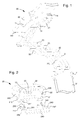
- la
figure 1 est une vue en perspective d'un fermoir conforme à l'invention ; - la
figure 2 est une vue éclatée des seconds moyens de verrouillage d'un fermoir conforme à l'invention ; - la
figure 3a est une vue de dessus des seconds moyens de verrouillage d'un fermoir conforme à l'invention ; - la
figure 3b est une vue en coupe selon la ligne AA de lafigure 3a des seconds moyens de verrouillage d'un fermoir conforme à l'invention ; - la
figure 4 est une vue en perspective d'un fermoir selon un deuxième mode de réalisation de l'invention ; - les
figures 5 ,6a et 6b sont des vues en perspectives d'un fermoir selon un troisième mode de réalisation de l'invention.
- the
figure 1 is a perspective view of a clasp according to the invention; - the
figure 2 is an exploded view of the second locking means of a clasp according to the invention; - the
figure 3a is a top view of the second locking means of a clasp according to the invention; - the
figure 3b is a sectional view along line AA of thefigure 3a second locking means of a clasp according to the invention; - the
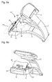
figure 4 is a perspective view of a clasp according to a second embodiment of the invention; - the
figures 5 ,6a and 6b are perspective views of a clasp according to a third embodiment of the invention.
Un fermoir pour bracelet à brin réglable selon un premier exemple de réalisation va maintenant être décrit dans ce qui suit faisant référence conjointement aux
Selon un premier mode de réalisation, l'invention concerne un fermoir pour bracelet, du type à boucle déployante, comprenant au moins des première et deuxième lames, la première lame 1 étant articulée à la deuxième lame 2 par une première extrémité, entre une position fermée, dite position de porter, dans laquelle la première lame 1 est repliée sur la deuxième lame 2, et une position ouverte dans laquelle la première lame 1 est dégagée de la deuxième lame 2.According to a first embodiment, the invention relates to a clasp for a bracelet, of the folding clasp type, comprising at least first and second blades, the
La première lame 1 porte à une seconde extrémité un organe de fixation 20 d'un premier brin 100 de bracelet, un second brin 101 de bracelet étant relié au moins indirectement à la deuxième lame 2 au moyen d'un maillon d'attache 11 par exemple, la première lame 1 comportant des premiers moyens de verrouillage aptes à maintenir la première lame 1 dans sa position fermée.The
Les brins 100, 101 peuvent être fabriqués dans des matériaux tels que du cuir, du tissu, de la toile, ou tout autre matériau connu de l'homme du métier pour réaliser des bracelets ou des ceintures.The
Les premiers moyens de verrouillage peuvent être formés, par exemple, par au moins une gâchette 32 configurée pour maintenir et/ou libérer un téton, dit téton inférieur 31, de façon à maintenir la première lame 1 dans sa position fermée contre la deuxième lame 2 ou libérer la première lame 1 dans sa position dégagée.The first locking means may be formed, for example, by at least one
La deuxième lame 2 peut, par exemple, présenter un orifice traversant en son centre, dit orifice central 25, l'orifice central étant configuré pour recevoir le téton inférieur 31 de manière que le téton inférieur 31 coopère avec la gâchette. Bien entendu, d'autres moyens de verrouillage auraient pu être envisagés par l'homme du métier dans le cadre de la présente invention.The
Comme on peut l'observer aux
- une plaque de
base 21 articulée en pivotement à la seconde extrémité de la première lame 1, la plaque de base étant maintenue par unebarrette 10, et un capot 22, en forme de U inversé, articulé en pivotement à laplaque de base 21,le capot 22 étant maintenu à laplaque de base 21 par ses bords latéraux au moyen de labarrette 10.
- a
base plate 21 pivotally articulated at the second end of thefirst blade 1, the base plate being held by abar 10, and - an inverted
U-shaped cowl 22 articulated pivotally to thebase plate 21, thecowl 22 being held at thebase plate 21 by its lateral edges by means of thebar 10.
Un tel agencement de la plaque de base 21 et du capot 22 permet au premier brin 100 de passer entre la plaque de base 21 et le capot 22. Avantageusement, le premier brin 100 passe au travers des moyens de réglage, au niveau de l'articulation du capot sur la plaque de base. Comme on peut l'observer sur les figures, le premier brin 100 est maintenu dans sa position par le biais de moyens de maintien tels qu'un téton, dit téton supérieur 30, destiné à être inséré dans un trou adapté du premier brin 100 pour définir un point d'ancrage de ce dernier au fermoir. Bien entendu, d'autres moyens de maintien auraient pu être envisagés par l'homme du métier dans le cadre de la présente invention.Such an arrangement of the
Les moyens de réglage comprennent également des seconds moyens de verrouillage pour maintenir en position fermée le capot 22 sur la plaque de base 21.The adjustment means also comprise second locking means for holding the
De manière avantageuse, les seconds moyens de verrouillage sont formés par un poussoir 24 agencé pour être déplacé suivant une direction longitudinale du premier brin 100, en réponse à une action de l'utilisateur, entre une première position de repos dans laquelle le capot 22 est verrouillé en position fermée sur la plaque de base 21, et une seconde position poussée dans laquelle le capot 22 est dégagé de la plaque de base 21.Advantageously, the second locking means are formed by a
Tel que représentés à la
La plaque de base 21 comprend des moyens de guidage pour le poussoir 24 et les ressorts 230, les moyens de guidage se présentant respectivement sous la forme d'une fente de guidage 210 de part et d'autre de la plaque de base 21 pour le poussoir 24 et d'un cylindre de guidage 211 pour chaque ressort 230, les ressorts 230 étant ainsi maintenus latéralement dans les cylindres de guidage 211.The
Avantageusement, les fentes de guidage 210 sont prévues débouchantes, de manière que le poussoir 24 peut coopérer avec les parois latérales du capot 21.Advantageously, the guide slots 210 are provided open, so that the
Le poussoir 24 est formé par un corps 240, de largeur équivalente à la largeur de la plaque de base 21, et présente un bras 241 disposé à chacune de ses extrémités, les bras 241 étant configurés pour coulisser au sein des fentes de guidage 210 et coopérer en appui avec les ressorts 230. Comme on peut l'observer sur les figures, chaque bras 241 du poussoir 24 comprend un pion 241 orienté vers l'extérieur de la fente de guidage 210 pour coopérer avec l'une des parois latérales 220 du capot 22.The
Le poussoir présente également un trou traversant 243 au niveau de chaque bras 241, chacun des trous traversants 243 étant configuré pour laisser passer une vis 212 fixée à la plaque de base 21 et ainsi maintenir le poussoir 24 en place alors qu'il est contraint par les ressorts 230. Les trous traversants 243 sont d'un diamètre plus grand que ceux des vis 212, la différence entre les diamètres du trou 243 et de la vis 212 définissant la longueur de course du poussoir 24.The pusher also has a through
Selon l'invention, le capot 22 présente une gorge en L 221 sur la face interne de chacune de ses parois latérales 220, disposée de manière préférentielle à proximité d'une de ses extrémités, chaque gorge en L 221 étant configurée pour coopérer avec un pion 241 respectif du poussoir 24.According to the invention, the
Selon une variante de réalisation, non représentée sur les figures, le capot 22 comprend sur la face interne de chacune de ses parois latérales 220 un pion, et chaque bras 241 du poussoir 24 comprend une gorge configurée pour coopérer avec un pion respectif du capot 22. Ainsi, lorsqu'un utilisateur presse le poussoir 24, les gorges se déplacent et libèrent les pions présents sur les parois latérales 220 du capot 22.According to an alternative embodiment, not shown in the figures, the
Comme on peut l'observer à la
Selon un aspect particulièrement avantageux de l'invention, l'utilisateur peut utiliser le même doigt pour presser le poussoir 24 et soulever le capot 22, le doigt arrivant à proximité immédiate du capot 22 une fois le poussoir en position poussée.According to a particularly advantageous aspect of the invention, the user can use the same finger to press the
Selon un deuxième mode de réalisation de l'invention, le fermoir pour bracelet, du type à boucle déployante, comprend des première, deuxième et troisième lames, la première lame 1 étant articulée à la deuxième lame 2 par une première extrémité, et la troisième lame 3 étant articulée à la deuxième lame 2 par la seconde extrémité opposée à la première extrémité.According to a second embodiment of the invention, the clasp for a bracelet, of the clasp type, comprises first, second and third blades, the
La première lame 1 et la troisième lame 3 peuvent passer d'une position fermée, dite position de porter, dans laquelle la première lame 1 et la troisième lame 3 sont repliées sur la deuxième lame 2, et une position ouverte dans laquelle la première lame 1 et la troisième lame 3 sont dégagées de la deuxième lame 2.The
La première lame 1 porte à sa seconde extrémité un organe de fixation 20 d'un premier brin 100 de bracelet, un second brin 101 de bracelet étant relié au moins indirectement à la deuxième lame 2, la première lame 1 comportant des premiers moyens de verrouillage 10 aptes à maintenir la première lame 1 dans sa position fermée.The
Comme on peut l'observer à la
Comme on peut l'observer sur la
Ainsi, la première lame 1 et la troisième lame 3 reposent au moins partiellement dans les logements longitudinaux 26 et 27, de manière que la seconde extrémité de la première lame 1 et de la troisième lame 3 repose sur la deuxième lame 2 à proximité immédiate de l'orifice central 25.Thus, the
Telle qu'illustrée à la
Selon ce mode de réalisation particulier de l'invention, l'organe de fixation 20 présente un réceptacle 200 dans lequel le corps 240 du poussoir 24 vient se loger lorsque la première lame 1 et la troisième lame 3 sont repliées sur la deuxième lame 2 en position fermée.According to this particular embodiment of the invention, the fixing
Pour fermer le fermoir, l'utilisateur replie dans un premier temps la troisième lame 3 sur la deuxième lame 2 dans l'évidement longitudinal 27 correspondant, de manière que la seconde extrémité de la troisième lame 3 soit positionnée au-dessus de l'orifice central 25. Ensuite, l'utilisateur replie la première lame 1 sur la deuxième lame 2 dans l'évidement longitudinal 26 correspondant, de manière que la seconde extrémité de la première lame 1 soit positionnée au-dessus de l'orifice central 25 et que la seconde extrémité de la troisième lame 3 repose au niveau de la creusure 213. Finalement, les lames 1 et 3 sont verrouillées une fois que l'utilisateur positionne le téton inférieur 31 dans l'orifice central 25 de façon à le verrouiller par le biais des premiers moyens de verrouillage.To close the clasp, the user folds at first the
Un fermoir pour bracelet à brin réglable selon un troisième exemple de réalisation va maintenant être décrit dans ce qui suit faisant référence conjointement aux
Selon ce troisième mode de réalisation, le fermoir comprend une première lame 1 articulée à une deuxième lame 2 par une première extrémité, entre une position fermée, dite position de porter, dans laquelle la première lame 1 est repliée sur la deuxième lame 2, et une position ouverte dans laquelle la première lame 1 est dégagée de la deuxième lame 2.According to this third embodiment, the clasp comprises a
La deuxième lame 2 porte à une seconde extrémité un organe de fixation 20 d'un premier brin 100 de bracelet, un second brin de bracelet pouvant être relié au moins indirectement à la première lame 1 au moyen d'une tige 13 par exemple, la première lame 1 comportant des premiers moyens de verrouillage aptes à maintenir la première lame 1 dans sa position fermée.The
Comme on peut l'observer sur la
Les premiers moyens de verrouillage peuvent être formés, par exemple, par au moins une gâchette 32 configurée pour maintenir et/ou libérer un téton, dit téton supérieur 30' sur la deuxième lame 2, de façon à maintenir la première lame 1 dans sa position fermée contre la deuxième lame 2 ou libérer la première lame 1 dans sa position dégagée.The first locking means may be formed, for example, by at least one
Selon un aspect particulièrement avantageux, la première lame 1 comprend un élément de guidage 12 qui permet de guider latéralement la première lame 1 par rapport à la deuxième lame 2 lorsque la première lame 1 est repliée sur la deuxième lame 2. Un autre avantage de cet élément de guidage 12 est d'empêcher la première lame 1 d'être déplacer latéralement et ainsi prévenir une usure, voire une casse, du pion supérieur 30' lorsque le fermoir est fermé.According to a particularly advantageous aspect, the
Comme on peut l'observer aux
Un tel agencement de la plaque de base 21 et de la deuxième lame 2 permet au premier brin 100 de passer sous la plaque de base 21 par le pont 40 de la deuxième lame 2. Avantageusement, le premier brin 100 passe au travers des moyens de réglage, au niveau de l'articulation de la plaque de base 21 Comme on peut l'observer sur les figures, le premier brin 100 est maintenu dans sa position par le biais de moyens de maintien tels qu'un téton, dit téton inférieur 31', destiné à être inséré dans un trou adapté du premier brin 100 pour définir un point d'ancrage de ce dernier au fermoir. Bien entendu, d'autres moyens de maintien auraient pu être envisagés par l'homme du métier dans le cadre de la présente invention.Such an arrangement of the
Les moyens de réglage comprennent également des seconds moyens de verrouillage pour maintenir en position fermée la plaque de base 21 sur la deuxième lame 2.The adjustment means also comprise second locking means for holding the
De manière avantageuse, les seconds moyens de verrouillage sont formés par un poussoir 24 agencé pour être déplacé suivant une direction longitudinale du premier brin 100, en réponse à une action de l'utilisateur, entre une première position de repos dans laquelle la plaque de base 21 est verrouillée en position fermée sur la deuxième lame 2, et une seconde position poussée dans laquelle la plaque de base 21 est dégagée de la deuxième lame 2.Advantageously, the second locking means are formed by a
Comme pour les modes de réalisation précédents, les seconds moyens de verrouillage comprennent des moyens de rappel, tels que des ressorts 230, configurés pour exercer une force sur le poussoir 24 de manière à maintenir le poussoir 24 en position fermée.As for the previous embodiments, the second locking means comprise return means, such as
La plaque de base 21 comprend des moyens de guidage pour le poussoir 24 et les ressorts 230, les moyens de guidage se présentant respectivement sous la forme d'une fente de guidage 210 de part et d'autre de la plaque de base 21 pour le poussoir 24 et d'un cylindre de guidage 211 pour chaque ressort 230, les ressorts 230 étant ainsi maintenu latéralement dans les cylindre de guidage 211.The
Le poussoir 24 est formé par un corps 240, de largeur équivalente à la largeur de la plaque de base 21, et présente un bras 241 disposé à chacune de ses extrémités, les bras 241 étant configurés pour coulisser au sein des fentes de guidage 210 et coopérer en appui avec les ressorts 230. Comme on peut l'observer sur les figures, chaque bras 241 du poussoir 24 comprend une gorge en L 221 orientée vers l'extérieur pour coopérer avec l'une des parois latérales 41, 42 du pont 40 de la deuxième lame 2.The
Selon l'invention, le pont 40 présente un pion 242 sur la face interne de chacune de ses parois latérales 41,42, disposé de manière préférentielle à proximité d'une de ses extrémités, chaque pion 242 étant configuré pour coopérer avec une gorge en L 221 respective du poussoir 24.According to the invention, the
Bien évidemment, l'homme du métier peut inverser la position des pions 242 et des gorges en L 221. Ainsi, les pions 242 peuvent se situer sur le poussoir 24 et les gorges en L 221 sur les parois latérales 41 et 42 du pont 40.Of course, the skilled person can reverse the position of the
Comme on peut l'observer à la
L'invention concerne également une montre-bracelet comportant un bracelet muni d'un fermoir tel que décrit précédemment.The invention also relates to a wristwatch comprising a bracelet provided with a clasp as described above.
L'invention concerne aussi un module de fixation d'un brin sur une attache, comme une attache de ceinture par exemple, le module de fixation étant muni de moyens de réglage de la longueur du brin, ces moyens de réglage comprenant :
- une plaque de
base 21 assujettie à la seconde extrémité de la première lame 1, etun capot 22 articulé en pivotement à laplaque de base 21, le brin passant entre laplaque de base 21 et le capot 22, le brin étant maintenu par le biais de moyens de maintien disposé sur la face supérieure et sur la face inférieure de laplaque de base 211, et - des seconds moyens de verrouillage du capot 21 sur la
plaque de base 21 en position fermée équipant laplaque de base 21.
- a
base plate 21 secured to the second end of thefirst blade 1, and acover 22 articulated pivotally to thebase plate 21, the strand passing between thebase plate 21 and thecover 22, the strand being held by the biasing means disposed on the upper face and the lower face of thebase plate 211, and - second cap locking means 21 on the
base plate 21 in the closed position equipping thebase plate 21.
Selon l'invention, les seconds moyens de verrouillage comprennent un poussoir 24 agencé pour être déplacé suivant une direction longitudinale du brin, en réponse à une action de l'utilisateur, entre une première position de repos dans laquelle le capot 22 est verrouillé en position fermée sur la plaque de base 21, et une seconde position poussée dans laquelle le capot 22 est dégagé de la plaque de base 21.According to the invention, the second locking means comprise a
Grâce à ces différents aspects de l'invention, on dispose d'un fermoir de conception simple permettant d'ajuster la longueur d'un brin de bracelet ou de ceinture par exemple.Thanks to these different aspects of the invention, there is a clasp of simple design for adjusting the length of a strand of bracelet or belt for example.
Bien entendu, la présente invention ne se limite pas à l'exemple illustré et est susceptible de diverses variantes et modifications qui apparaîtront à l'homme de l'art.
Claims (15)
l'organe de fixation (20) comprenant des moyens de réglage de la longueur utile du bracelet, ces moyens de réglage comprenant :
the fixing member (20) comprising means for adjusting the useful length of the bracelet, these adjustment means comprising:
l'organe de fixation (20) comprenant des moyens de réglage de la longueur utile du bracelet, ces moyens de réglage comprenant :
the fixing member (20) comprising means for adjusting the useful length of the bracelet, these adjustment means comprising:
Priority Applications (5)
| Application Number | Priority Date | Filing Date | Title |
|---|---|---|---|
| EP15164867.2A EP3085265B1 (en) | 2015-04-23 | 2015-04-23 | Clasp for bracelet |
| US15/085,310 US10278460B2 (en) | 2015-04-23 | 2016-03-30 | Bracelet clasp |
| JP2016078761A JP6280589B2 (en) | 2015-04-23 | 2016-04-11 | Clasp clasp |
| KR1020160049493A KR101855068B1 (en) | 2015-04-23 | 2016-04-22 | Bracelet clasp |
| CN201610257154.8A CN106063620B (en) | 2015-04-23 | 2016-04-22 | Chain clasp |
Applications Claiming Priority (1)
| Application Number | Priority Date | Filing Date | Title |
|---|---|---|---|
| EP15164867.2A EP3085265B1 (en) | 2015-04-23 | 2015-04-23 | Clasp for bracelet |
Publications (2)
| Publication Number | Publication Date |
|---|---|
| EP3085265A1 true EP3085265A1 (en) | 2016-10-26 |
| EP3085265B1 EP3085265B1 (en) | 2020-12-30 |
Family
ID=53002556
Family Applications (1)
| Application Number | Title | Priority Date | Filing Date |
|---|---|---|---|
| EP15164867.2A Active EP3085265B1 (en) | 2015-04-23 | 2015-04-23 | Clasp for bracelet |
Country Status (5)
| Country | Link |
|---|---|
| US (1) | US10278460B2 (en) |
| EP (1) | EP3085265B1 (en) |
| JP (1) | JP6280589B2 (en) |
| KR (1) | KR101855068B1 (en) |
| CN (1) | CN106063620B (en) |
Cited By (1)
| Publication number | Priority date | Publication date | Assignee | Title |
|---|---|---|---|---|
| CN108991661A (en) * | 2017-06-07 | 2018-12-14 | 奥米加股份有限公司 | Chain clasp |
Families Citing this family (10)
| Publication number | Priority date | Publication date | Assignee | Title |
|---|---|---|---|---|
| US9949537B2 (en) * | 2015-03-06 | 2018-04-24 | Apple Inc. | Clasp mechanism for wrist-worn devices |
| CN107019297B (en) * | 2016-01-29 | 2021-02-12 | 精工爱普生株式会社 | Watch buckle, watch band and watch |
| EP3501325B1 (en) * | 2017-12-19 | 2020-07-22 | Omega SA | Clasp for bracelet |
| USD877647S1 (en) * | 2018-01-16 | 2020-03-10 | Frank Boschman | Bracelet clasp for jewellery |
| CH715059A1 (en) * | 2018-05-31 | 2019-12-13 | Richemont Int Sa | Folding clasp for wristwatch and method for retrofitting one. |
| EP3666110B1 (en) * | 2018-12-13 | 2022-04-20 | Omega SA | Adjustable bracelet clasp |
| CH715815A1 (en) * | 2019-02-04 | 2020-08-14 | Bucherer Ag | Metallic watch strap. |
| USD979442S1 (en) * | 2022-01-04 | 2023-02-28 | Lu Wang | Watch band |
| USD1012765S1 (en) * | 2023-09-05 | 2024-01-30 | Zhonghua Wu | Watch buckle |
| USD1018352S1 (en) * | 2023-09-05 | 2024-03-19 | Zhonghua Wu | Watch buckle |
Citations (5)
| Publication number | Priority date | Publication date | Assignee | Title |
|---|---|---|---|---|
| DE61468C (en) * | J. schiffers in Düsseldorf | Easily detachable buckle | ||
| EP0344620A1 (en) * | 1988-05-31 | 1989-12-06 | G.T.F. S.r.l. | Closing device for watch-straps, bracelets, jewels and similar |
| EP0607726A1 (en) | 1992-12-28 | 1994-07-27 | Maier S.A. | Foldable fastener for a bracelet with an adjustable end |
| EP1943917A2 (en) * | 2007-01-10 | 2008-07-16 | Boucledor SA | Clasp with extensible loop for bracelet |
| CH702523A2 (en) * | 2010-01-08 | 2011-07-15 | Richemont Int Sa | Strap's effective length adjusting device for unfolding buckle clasp of timepiece, has toothed wheels arranged at two sides of toothed bar in reference to longitudinal axis of bar, one of wheels cooperates with bar to adjust length of strap |
Family Cites Families (28)
| Publication number | Priority date | Publication date | Assignee | Title |
|---|---|---|---|---|
| US1741421A (en) * | 1929-01-16 | 1929-12-31 | Louis Stern Company | Foldable extension device |
| US3665564A (en) * | 1970-06-02 | 1972-05-30 | Bambi Kk | Three-fold metal fitting for adjusting steplessly the length of a watch band |
| US3797716A (en) * | 1970-10-24 | 1974-03-19 | Mochizuki Mfg Co Ltd | Watch band |
| IT8321828V0 (en) * | 1983-05-13 | 1983-05-13 | Lascor Spa | EXTENSIBLE CLOSURE CLASP, IN PARTICULAR FOR FLEXIBLE LEATHER STRAP OR PLASTIC MATERIAL FOR WATCH |
| JPH06327508A (en) * | 1993-03-26 | 1994-11-29 | Citizen Watch Co Ltd | Middle holding structure for watch band |
| GB2278148B (en) * | 1993-04-23 | 1996-08-21 | Ming Fung Metal Manufacturing | Wrist watch buckle |
| WO1996028064A1 (en) * | 1995-03-15 | 1996-09-19 | Citizen Watch Co., Ltd. | Device for fine adjustment of length of band-shaped accessory |
| WO1997029660A1 (en) * | 1996-02-12 | 1997-08-21 | Gay Freres Vente Et Exportation S.A. | Strap clasp |
| JP4445129B2 (en) * | 1998-07-02 | 2010-04-07 | シチズンホールディングス株式会社 | Nakadome of belt-like jewelry |
| EP1378185B1 (en) * | 2001-03-19 | 2011-08-24 | Citizen Holdings Co., Ltd. | Length adjustment device of band-shaped ornament |
| US6792652B2 (en) * | 2003-02-25 | 2004-09-21 | Luigi Ferrario | Unfolding clasp for bracelet |
| JP4545547B2 (en) * | 2004-10-20 | 2010-09-15 | シチズンホールディングス株式会社 | Trinket structure of jewelry |
| JP5149498B2 (en) * | 2006-09-07 | 2013-02-20 | 株式会社バンビ | Trinket structure of jewelry band |
| JP5354434B2 (en) * | 2007-05-24 | 2013-11-27 | 株式会社バンビ | Three-fold type Nakadome structure for a band and a watch having the same |
| CH702061A1 (en) | 2009-10-26 | 2011-04-29 | Thi Technologies Horlogeres Ind S A | Stretch bracelet clasp. |
| EP2534970B1 (en) * | 2011-06-16 | 2014-04-16 | Montres Breguet SA | Triple-opening clasp |
| EP2601856A1 (en) * | 2011-12-09 | 2013-06-12 | Omega SA | Watch strap clasp |
| EP2601855A1 (en) * | 2011-12-09 | 2013-06-12 | Omega SA | Watch strap clasp |
| EP2606762B1 (en) * | 2011-12-22 | 2015-08-12 | Montres Tudor S.A. | Clasp with different bracelet length settings |
| EP2702891B1 (en) * | 2012-09-04 | 2015-11-18 | Omega SA | Clasp for watch strap or garment belt |
| JP6201482B2 (en) * | 2012-09-20 | 2017-09-27 | カシオ計算機株式会社 | Jig for attaching and detaching frame body |
| EP2767184B1 (en) * | 2013-02-13 | 2015-04-08 | Omega SA | Watch strap clasp |
| EP2870893B1 (en) * | 2013-11-07 | 2016-06-08 | The Swatch Group Management Services AG | Bracelet clasp |
| EP2997847B1 (en) * | 2014-09-19 | 2018-04-18 | Omega SA | Clasp for a bracelet or belt |
| KR102234724B1 (en) * | 2014-09-23 | 2021-04-01 | 삼성전자 주식회사 | Buckle apparatus for a wearable device |
| EP3011857B1 (en) * | 2014-10-24 | 2017-03-15 | The Swatch Group Management Services AG | Bracelet clasp |
| US9681711B2 (en) * | 2015-05-28 | 2017-06-20 | Fossil Group, Inc. | Adjustable bracelet |
| CN107019297B (en) * | 2016-01-29 | 2021-02-12 | 精工爱普生株式会社 | Watch buckle, watch band and watch |
-
2015
- 2015-04-23 EP EP15164867.2A patent/EP3085265B1/en active Active
-
2016
- 2016-03-30 US US15/085,310 patent/US10278460B2/en active Active
- 2016-04-11 JP JP2016078761A patent/JP6280589B2/en active Active
- 2016-04-22 KR KR1020160049493A patent/KR101855068B1/en active IP Right Grant
- 2016-04-22 CN CN201610257154.8A patent/CN106063620B/en active Active
Patent Citations (5)
| Publication number | Priority date | Publication date | Assignee | Title |
|---|---|---|---|---|
| DE61468C (en) * | J. schiffers in Düsseldorf | Easily detachable buckle | ||
| EP0344620A1 (en) * | 1988-05-31 | 1989-12-06 | G.T.F. S.r.l. | Closing device for watch-straps, bracelets, jewels and similar |
| EP0607726A1 (en) | 1992-12-28 | 1994-07-27 | Maier S.A. | Foldable fastener for a bracelet with an adjustable end |
| EP1943917A2 (en) * | 2007-01-10 | 2008-07-16 | Boucledor SA | Clasp with extensible loop for bracelet |
| CH702523A2 (en) * | 2010-01-08 | 2011-07-15 | Richemont Int Sa | Strap's effective length adjusting device for unfolding buckle clasp of timepiece, has toothed wheels arranged at two sides of toothed bar in reference to longitudinal axis of bar, one of wheels cooperates with bar to adjust length of strap |
Cited By (2)
| Publication number | Priority date | Publication date | Assignee | Title |
|---|---|---|---|---|
| CN108991661A (en) * | 2017-06-07 | 2018-12-14 | 奥米加股份有限公司 | Chain clasp |
| US10932532B2 (en) | 2017-06-07 | 2021-03-02 | Omega Sa | Bracelet clasp |
Also Published As
| Publication number | Publication date |
|---|---|
| CN106063620B (en) | 2018-01-30 |
| US20160309859A1 (en) | 2016-10-27 |
| EP3085265B1 (en) | 2020-12-30 |
| US10278460B2 (en) | 2019-05-07 |
| KR20160126913A (en) | 2016-11-02 |
| JP2016202899A (en) | 2016-12-08 |
| JP6280589B2 (en) | 2018-02-14 |
| KR101855068B1 (en) | 2018-05-09 |
| CN106063620A (en) | 2016-11-02 |
Similar Documents
| Publication | Publication Date | Title |
|---|---|---|
| EP2997847B1 (en) | Clasp for a bracelet or belt | |
| EP3085265B1 (en) | Clasp for bracelet | |
| EP3412168B1 (en) | Clasp for bracelet | |
| EP3769640B1 (en) | Watch strap clasp | |
| EP2361523B1 (en) | Clasp for bracelet | |
| EP1836917B1 (en) | Length adjustable wristband | |
| CH700230B1 (en) | bracelet clasp comprising a fine adjustment device of the useful length of the bracelet. | |
| EP3501325B1 (en) | Clasp for bracelet | |
| EP0661938B1 (en) | Unfolding buckle-type clasp for a bracelet | |
| CH698981B1 (en) | Bracelet clasp i.e. folding arm type clasp, length adjusting device for e.g. diving watch, has frame carrying control unit that is movable in transversal direction, acts on locking unit when control unit is activated, and displaces support | |
| EP0862097B1 (en) | Bar for fastening a watch band and watch provided with such a bar | |
| CH710133A2 (en) | Clasp for strap or belt. | |
| FR3058030B1 (en) | SECURE LOOP | |
| CH711022A2 (en) | Clasp bracelet. | |
| EP4059374A1 (en) | Bracelet clasp comprising a device for adjusting the length of the bracelet allowing rapid fitting | |
| CH712319A1 (en) | Device for setting the length of a clasp for a bracelet or belt. | |
| EP3417734B1 (en) | Bracelet clasp comprising a device for adjusting the length of the bracelet | |
| CH713856A2 (en) | Clasp for bracelet. | |
| CH714461B1 (en) | Clasp for bracelet with setting at ease. | |
| CH712039B1 (en) | Folding clasp for bracelet. | |
| EP4005427B1 (en) | Clasp for a bracelet or belt | |
| CH684151A5 (en) | Bracelet clasp | |
| FR2743641A1 (en) | Wristwatch bracelet attachment apparatus | |
| CH702308B1 (en) | Portable object having an interchangeable strap. | |
| CH718094A2 (en) | Clasp for bracelet or belt. |
Legal Events
| Date | Code | Title | Description |
|---|---|---|---|
| PUAI | Public reference made under article 153(3) epc to a published international application that has entered the european phase |
Free format text: ORIGINAL CODE: 0009012 |
|
| AK | Designated contracting states |
Kind code of ref document: A1 Designated state(s): AL AT BE BG CH CY CZ DE DK EE ES FI FR GB GR HR HU IE IS IT LI LT LU LV MC MK MT NL NO PL PT RO RS SE SI SK SM TR |
|
| AX | Request for extension of the european patent |
Extension state: BA ME |
|
| 17P | Request for examination filed |
Effective date: 20170426 |
|
| RBV | Designated contracting states (corrected) |
Designated state(s): AL AT BE BG CH CY CZ DE DK EE ES FI FR GB GR HR HU IE IS IT LI LT LU LV MC MK MT NL NO PL PT RO RS SE SI SK SM TR |
|
| STAA | Information on the status of an ep patent application or granted ep patent |
Free format text: STATUS: REQUEST FOR EXAMINATION WAS MADE |
|
| STAA | Information on the status of an ep patent application or granted ep patent |
Free format text: STATUS: EXAMINATION IS IN PROGRESS |
|
| 17Q | First examination report despatched |
Effective date: 20191121 |
|
| GRAP | Despatch of communication of intention to grant a patent |
Free format text: ORIGINAL CODE: EPIDOSNIGR1 |
|
| STAA | Information on the status of an ep patent application or granted ep patent |
Free format text: STATUS: GRANT OF PATENT IS INTENDED |
|
| INTG | Intention to grant announced |
Effective date: 20200910 |
|
| GRAS | Grant fee paid |
Free format text: ORIGINAL CODE: EPIDOSNIGR3 |
|
| GRAA | (expected) grant |
Free format text: ORIGINAL CODE: 0009210 |
|
| STAA | Information on the status of an ep patent application or granted ep patent |
Free format text: STATUS: THE PATENT HAS BEEN GRANTED |
|
| AK | Designated contracting states |
Kind code of ref document: B1 Designated state(s): AL AT BE BG CH CY CZ DE DK EE ES FI FR GB GR HR HU IE IS IT LI LT LU LV MC MK MT NL NO PL PT RO RS SE SI SK SM TR |
|
| REG | Reference to a national code |
Ref country code: GB Ref legal event code: FG4D Free format text: NOT ENGLISH |
|
| REG | Reference to a national code |
Ref country code: DE Ref legal event code: R096 Ref document number: 602015064035 Country of ref document: DE |
|
| REG | Reference to a national code |
Ref country code: AT Ref legal event code: REF Ref document number: 1349059 Country of ref document: AT Kind code of ref document: T Effective date: 20210115 |
|
| REG | Reference to a national code |
Ref country code: CH Ref legal event code: NV Representative=s name: ICB INGENIEURS CONSEILS EN BREVETS SA, CH |
|
| REG | Reference to a national code |
Ref country code: IE Ref legal event code: FG4D Free format text: LANGUAGE OF EP DOCUMENT: FRENCH |
|
| PG25 | Lapsed in a contracting state [announced via postgrant information from national office to epo] |
Ref country code: FI Free format text: LAPSE BECAUSE OF FAILURE TO SUBMIT A TRANSLATION OF THE DESCRIPTION OR TO PAY THE FEE WITHIN THE PRESCRIBED TIME-LIMIT Effective date: 20201230 Ref country code: RS Free format text: LAPSE BECAUSE OF FAILURE TO SUBMIT A TRANSLATION OF THE DESCRIPTION OR TO PAY THE FEE WITHIN THE PRESCRIBED TIME-LIMIT Effective date: 20201230 Ref country code: NO Free format text: LAPSE BECAUSE OF FAILURE TO SUBMIT A TRANSLATION OF THE DESCRIPTION OR TO PAY THE FEE WITHIN THE PRESCRIBED TIME-LIMIT Effective date: 20210330 Ref country code: GR Free format text: LAPSE BECAUSE OF FAILURE TO SUBMIT A TRANSLATION OF THE DESCRIPTION OR TO PAY THE FEE WITHIN THE PRESCRIBED TIME-LIMIT Effective date: 20210331 |
|
| REG | Reference to a national code |
Ref country code: AT Ref legal event code: MK05 Ref document number: 1349059 Country of ref document: AT Kind code of ref document: T Effective date: 20201230 |
|
| PG25 | Lapsed in a contracting state [announced via postgrant information from national office to epo] |
Ref country code: LV Free format text: LAPSE BECAUSE OF FAILURE TO SUBMIT A TRANSLATION OF THE DESCRIPTION OR TO PAY THE FEE WITHIN THE PRESCRIBED TIME-LIMIT Effective date: 20201230 Ref country code: SE Free format text: LAPSE BECAUSE OF FAILURE TO SUBMIT A TRANSLATION OF THE DESCRIPTION OR TO PAY THE FEE WITHIN THE PRESCRIBED TIME-LIMIT Effective date: 20201230 Ref country code: BG Free format text: LAPSE BECAUSE OF FAILURE TO SUBMIT A TRANSLATION OF THE DESCRIPTION OR TO PAY THE FEE WITHIN THE PRESCRIBED TIME-LIMIT Effective date: 20210330 |
|
| REG | Reference to a national code |
Ref country code: NL Ref legal event code: MP Effective date: 20201230 |
|
| PG25 | Lapsed in a contracting state [announced via postgrant information from national office to epo] |
Ref country code: HR Free format text: LAPSE BECAUSE OF FAILURE TO SUBMIT A TRANSLATION OF THE DESCRIPTION OR TO PAY THE FEE WITHIN THE PRESCRIBED TIME-LIMIT Effective date: 20201230 |
|
| REG | Reference to a national code |
Ref country code: LT Ref legal event code: MG9D |
|
| PG25 | Lapsed in a contracting state [announced via postgrant information from national office to epo] |
Ref country code: SK Free format text: LAPSE BECAUSE OF FAILURE TO SUBMIT A TRANSLATION OF THE DESCRIPTION OR TO PAY THE FEE WITHIN THE PRESCRIBED TIME-LIMIT Effective date: 20201230 Ref country code: PT Free format text: LAPSE BECAUSE OF FAILURE TO SUBMIT A TRANSLATION OF THE DESCRIPTION OR TO PAY THE FEE WITHIN THE PRESCRIBED TIME-LIMIT Effective date: 20210430 Ref country code: RO Free format text: LAPSE BECAUSE OF FAILURE TO SUBMIT A TRANSLATION OF THE DESCRIPTION OR TO PAY THE FEE WITHIN THE PRESCRIBED TIME-LIMIT Effective date: 20201230 Ref country code: LT Free format text: LAPSE BECAUSE OF FAILURE TO SUBMIT A TRANSLATION OF THE DESCRIPTION OR TO PAY THE FEE WITHIN THE PRESCRIBED TIME-LIMIT Effective date: 20201230 Ref country code: EE Free format text: LAPSE BECAUSE OF FAILURE TO SUBMIT A TRANSLATION OF THE DESCRIPTION OR TO PAY THE FEE WITHIN THE PRESCRIBED TIME-LIMIT Effective date: 20201230 Ref country code: CZ Free format text: LAPSE BECAUSE OF FAILURE TO SUBMIT A TRANSLATION OF THE DESCRIPTION OR TO PAY THE FEE WITHIN THE PRESCRIBED TIME-LIMIT Effective date: 20201230 Ref country code: NL Free format text: LAPSE BECAUSE OF FAILURE TO SUBMIT A TRANSLATION OF THE DESCRIPTION OR TO PAY THE FEE WITHIN THE PRESCRIBED TIME-LIMIT Effective date: 20201230 |
|
| PG25 | Lapsed in a contracting state [announced via postgrant information from national office to epo] |
Ref country code: PL Free format text: LAPSE BECAUSE OF FAILURE TO SUBMIT A TRANSLATION OF THE DESCRIPTION OR TO PAY THE FEE WITHIN THE PRESCRIBED TIME-LIMIT Effective date: 20201230 Ref country code: AT Free format text: LAPSE BECAUSE OF FAILURE TO SUBMIT A TRANSLATION OF THE DESCRIPTION OR TO PAY THE FEE WITHIN THE PRESCRIBED TIME-LIMIT Effective date: 20201230 |
|
| PG25 | Lapsed in a contracting state [announced via postgrant information from national office to epo] |
Ref country code: IS Free format text: LAPSE BECAUSE OF FAILURE TO SUBMIT A TRANSLATION OF THE DESCRIPTION OR TO PAY THE FEE WITHIN THE PRESCRIBED TIME-LIMIT Effective date: 20210430 |
|
| REG | Reference to a national code |
Ref country code: DE Ref legal event code: R097 Ref document number: 602015064035 Country of ref document: DE |
|
| PG25 | Lapsed in a contracting state [announced via postgrant information from national office to epo] |
Ref country code: IT Free format text: LAPSE BECAUSE OF FAILURE TO SUBMIT A TRANSLATION OF THE DESCRIPTION OR TO PAY THE FEE WITHIN THE PRESCRIBED TIME-LIMIT Effective date: 20201230 Ref country code: AL Free format text: LAPSE BECAUSE OF FAILURE TO SUBMIT A TRANSLATION OF THE DESCRIPTION OR TO PAY THE FEE WITHIN THE PRESCRIBED TIME-LIMIT Effective date: 20201230 |
|
| PLBE | No opposition filed within time limit |
Free format text: ORIGINAL CODE: 0009261 |
|
| STAA | Information on the status of an ep patent application or granted ep patent |
Free format text: STATUS: NO OPPOSITION FILED WITHIN TIME LIMIT |
|
| PG25 | Lapsed in a contracting state [announced via postgrant information from national office to epo] |
Ref country code: ES Free format text: LAPSE BECAUSE OF FAILURE TO SUBMIT A TRANSLATION OF THE DESCRIPTION OR TO PAY THE FEE WITHIN THE PRESCRIBED TIME-LIMIT Effective date: 20201230 Ref country code: DK Free format text: LAPSE BECAUSE OF FAILURE TO SUBMIT A TRANSLATION OF THE DESCRIPTION OR TO PAY THE FEE WITHIN THE PRESCRIBED TIME-LIMIT Effective date: 20201230 Ref country code: MC Free format text: LAPSE BECAUSE OF FAILURE TO SUBMIT A TRANSLATION OF THE DESCRIPTION OR TO PAY THE FEE WITHIN THE PRESCRIBED TIME-LIMIT Effective date: 20201230 |
|
| 26N | No opposition filed |
Effective date: 20211001 |
|
| PG25 | Lapsed in a contracting state [announced via postgrant information from national office to epo] |
Ref country code: LU Free format text: LAPSE BECAUSE OF NON-PAYMENT OF DUE FEES Effective date: 20210423 |
|
| REG | Reference to a national code |
Ref country code: BE Ref legal event code: MM Effective date: 20210430 |
|
| PG25 | Lapsed in a contracting state [announced via postgrant information from national office to epo] |
Ref country code: SI Free format text: LAPSE BECAUSE OF FAILURE TO SUBMIT A TRANSLATION OF THE DESCRIPTION OR TO PAY THE FEE WITHIN THE PRESCRIBED TIME-LIMIT Effective date: 20201230 |
|
| PG25 | Lapsed in a contracting state [announced via postgrant information from national office to epo] |
Ref country code: IE Free format text: LAPSE BECAUSE OF NON-PAYMENT OF DUE FEES Effective date: 20210423 |
|
| PG25 | Lapsed in a contracting state [announced via postgrant information from national office to epo] |
Ref country code: IS Free format text: LAPSE BECAUSE OF FAILURE TO SUBMIT A TRANSLATION OF THE DESCRIPTION OR TO PAY THE FEE WITHIN THE PRESCRIBED TIME-LIMIT Effective date: 20210430 |
|
| PG25 | Lapsed in a contracting state [announced via postgrant information from national office to epo] |
Ref country code: BE Free format text: LAPSE BECAUSE OF NON-PAYMENT OF DUE FEES Effective date: 20210430 |
|
| PGFP | Annual fee paid to national office [announced via postgrant information from national office to epo] |
Ref country code: FR Payment date: 20230321 Year of fee payment: 9 |
|
| PG25 | Lapsed in a contracting state [announced via postgrant information from national office to epo] |
Ref country code: HU Free format text: LAPSE BECAUSE OF FAILURE TO SUBMIT A TRANSLATION OF THE DESCRIPTION OR TO PAY THE FEE WITHIN THE PRESCRIBED TIME-LIMIT; INVALID AB INITIO Effective date: 20150423 |
|
| PGFP | Annual fee paid to national office [announced via postgrant information from national office to epo] |
Ref country code: GB Payment date: 20230321 Year of fee payment: 9 |
|
| PG25 | Lapsed in a contracting state [announced via postgrant information from national office to epo] |
Ref country code: CY Free format text: LAPSE BECAUSE OF FAILURE TO SUBMIT A TRANSLATION OF THE DESCRIPTION OR TO PAY THE FEE WITHIN THE PRESCRIBED TIME-LIMIT Effective date: 20201230 |
|
| PG25 | Lapsed in a contracting state [announced via postgrant information from national office to epo] |
Ref country code: SM Free format text: LAPSE BECAUSE OF FAILURE TO SUBMIT A TRANSLATION OF THE DESCRIPTION OR TO PAY THE FEE WITHIN THE PRESCRIBED TIME-LIMIT Effective date: 20201230 |
|
| PGFP | Annual fee paid to national office [announced via postgrant information from national office to epo] |
Ref country code: DE Payment date: 20230321 Year of fee payment: 9 Ref country code: CH Payment date: 20230502 Year of fee payment: 9 |
|
| P01 | Opt-out of the competence of the unified patent court (upc) registered |
Effective date: 20230701 |