EP3085256A1 - Electronic cigarette control circuit, electronic cigarette, and control method for electronic cigarette - Google Patents
Electronic cigarette control circuit, electronic cigarette, and control method for electronic cigarette Download PDFInfo
- Publication number
- EP3085256A1 EP3085256A1 EP13899665.7A EP13899665A EP3085256A1 EP 3085256 A1 EP3085256 A1 EP 3085256A1 EP 13899665 A EP13899665 A EP 13899665A EP 3085256 A1 EP3085256 A1 EP 3085256A1
- Authority
- EP
- European Patent Office
- Prior art keywords
- signal
- electronic cigarette
- unit
- control circuit
- comparison
- Prior art date
- Legal status (The legal status is an assumption and is not a legal conclusion. Google has not performed a legal analysis and makes no representation as to the accuracy of the status listed.)
- Withdrawn
Links
- 239000003571 electronic cigarette Substances 0.000 title claims abstract description 101
- 238000000034 method Methods 0.000 title claims abstract description 24
- 238000010438 heat treatment Methods 0.000 claims abstract description 57
- 235000019504 cigarettes Nutrition 0.000 claims abstract description 15
- 230000001960 triggered effect Effects 0.000 claims description 29
- 230000000052 comparative effect Effects 0.000 claims description 13
- 230000000391 smoking effect Effects 0.000 abstract description 31
- 235000019640 taste Nutrition 0.000 abstract description 12
- 230000009286 beneficial effect Effects 0.000 abstract 1
- 239000000779 smoke Substances 0.000 description 14
- 238000010586 diagram Methods 0.000 description 5
- 230000008859 change Effects 0.000 description 4
- 238000006243 chemical reaction Methods 0.000 description 4
- 238000000889 atomisation Methods 0.000 description 3
- 230000000694 effects Effects 0.000 description 3
- 230000004044 response Effects 0.000 description 3
- 230000005764 inhibitory process Effects 0.000 description 2
- 230000003321 amplification Effects 0.000 description 1
- 230000005611 electricity Effects 0.000 description 1
- 230000004048 modification Effects 0.000 description 1
- 238000012986 modification Methods 0.000 description 1
- 238000003199 nucleic acid amplification method Methods 0.000 description 1
- 238000005457 optimization Methods 0.000 description 1
- 230000008569 process Effects 0.000 description 1
- 239000002699 waste material Substances 0.000 description 1
Images

Classifications
-
- A—HUMAN NECESSITIES
- A24—TOBACCO; CIGARS; CIGARETTES; SIMULATED SMOKING DEVICES; SMOKERS' REQUISITES
- A24F—SMOKERS' REQUISITES; MATCH BOXES; SIMULATED SMOKING DEVICES
- A24F40/00—Electrically operated smoking devices; Component parts thereof; Manufacture thereof; Maintenance or testing thereof; Charging means specially adapted therefor
- A24F40/50—Control or monitoring
-
- A—HUMAN NECESSITIES
- A24—TOBACCO; CIGARS; CIGARETTES; SIMULATED SMOKING DEVICES; SMOKERS' REQUISITES
- A24F—SMOKERS' REQUISITES; MATCH BOXES; SIMULATED SMOKING DEVICES
- A24F40/00—Electrically operated smoking devices; Component parts thereof; Manufacture thereof; Maintenance or testing thereof; Charging means specially adapted therefor
- A24F40/30—Devices using two or more structurally separated inhalable precursors, e.g. using two liquid precursors in two cartridges
-
- A—HUMAN NECESSITIES
- A24—TOBACCO; CIGARS; CIGARETTES; SIMULATED SMOKING DEVICES; SMOKERS' REQUISITES
- A24F—SMOKERS' REQUISITES; MATCH BOXES; SIMULATED SMOKING DEVICES
- A24F40/00—Electrically operated smoking devices; Component parts thereof; Manufacture thereof; Maintenance or testing thereof; Charging means specially adapted therefor
- A24F40/10—Devices using liquid inhalable precursors
Definitions
- the present application relates to the technical field of electronic products, and more particularly, relates to electronic cigarette control circuit, electronic cigarette, and control method for electronic cigarette.
- An electronic cigarette is comprised of an atomization assembly and a battery rod.
- the atomization assembly comprises an oil-storage component for storing oil and a heating component for heating oil.
- the heating component heats, the oil in corresponding oil-storage component is atomized into smoke, then the smoke is exported from a nozzle to achieve the effect of smoking.
- the battery rod contains an air pressure driving switch and a power supply module. In response to the pressure produced by air flow when smoking, the power supply module is triggered to supply power to the heating component, then the heating element heats up the oil to generate smoke.
- the objective of the present application is to provide an improved electronic cigarette control circuit, electronic cigarette, and control method for electronic cigarette, aiming at the drawbacks in the prior art that, it is difficult to achieve an experience that the amount and taste of smoke can be changed on the basis of the exerted smoking strength which can be satisfied when smoking a real cigarette.
- the present application provides an electronic cigarette control circuit which is utilized for controlling an electronic cigarette, wherein, the control circuit comprises at least one airflow sensor, a control module, at least two switch units, and corresponding at least two heating components, and one of the at least two heating components is connected to one of the least two switch units correspondingly; the at least two switch units and the at least one airflow sensor are connected to the control module respectively;
- the airflow sensor is used for collecting an airflow signal of each instance of inhalation of the electronic cigarette and for transmitting the airflow signal to the control module;
- the control module is used for comparing the value of the airflow signal of each instance with a predetermined value and for selecting, on the basis of a comparison result, to transmit a conduction signal to at least one switch unit of the at least two switch units;
- the at least one switch unit is turned on upon receiving the conduction signal to allow corresponding at least one heating component to heat up;
- the at least one heating component is used for heating up cigarette oil in corresponding at least one oil-storage component to atomize the cigarette oil.
- the electronic cigarette control circuit further comprises an electric power supply module, and the electric power supply module is connected to the control module and each of the at least two switch units respectively; the electric power supply module is used to provide electric power to the control module, each of the at least two switch units and each of the at least two heating components.
- control module is a microprocessor
- the microprocessor comprises a memory unit, a comparing unit and a control unit; the comparing unit is connected to the airflow sensor and the control unit respectively, and the control unit is connected to the at least two switch units respectively; the memory unit is connected to the comparing unit;
- the memory unit is used to store at least two predetermined values
- the comparing unit is used to compare the peak value of the airflow signal with each of the predetermined values, then select a maximum predetermined value from the at least two predetermined values, and the maximum predetermined value should be less than the peak value of the airflow signal; the comparing unit then transmits a signal of the comparison result to the control unit on the basis of the maximum predetermined value; according to the signal of comparison result, the control unit transmits the conduction signal to at least one switch unit of the at least two switch units.
- the microprocessor further comprises a timing unit; the timing unit is connected to the control unit, and the control unit transmits a trigger signal to the timing unit when the control unit transmits the conduction signal; the timing unit receives the trigger signal and begins to time, and transmits a feedback signal to the control unit after timing a predetermined time; according to the feedback signal, the control unit transmits a close signal to the at least one switch unit which is in a conducting state; upon receiving the close signal, the at least one switch unit, is switched off to stop the corresponding at least one heating component from heating up.
- the control module comprises at least two comparison control circuits, and an input terminal of each of the comparison control circuits is correspondingly connected to the airflow sensor; an output terminal of each of the comparison control circuits is correspondingly connected to one of the at least two switch units, and the predetermined values are set to increase successively by the at least two comparison control circuits, and then the airflow signal triggers the comparison control circuits whose predetermined values are smaller than the value of the airflow signal;
- the comparison control circuit with a larger predetermined value suppresses and closes the comparison control circuit with a smaller predetermined value, and the comparison control circuit with the maximum predetermined value outputs the conduction signal.
- each of the comparison control circuits comprises a first comparison control circuit and a second comparison control circuit, and a comparative voltage input terminal of the first comparison control circuit is connected to the airflow sensor; one of the predetermined values is taken as a reference voltage by a reference voltage terminal of the first comparison control circuit, and an output terminal of the first comparison control circuit with a larger predetermined value between the two adjacent comparison control circuits is connected to a reference voltage terminal of the second comparison control circuit which is corresponding to the first comparison control circuit with a smaller predetermined value; comparative voltage input terminal of the second comparison control circuit is connected to the output terminal of the first comparison control circuit; the first comparison control circuit is used to compare the value of the airflow signal with each of the predetermined values, and a second voltage is transmitted to the comparative voltage input terminal of the second comparison control circuit by an output terminal of the first comparison control circuit with a predetermined value less than the value of the airflow signal.
- control module further comprises at least two time delay units, and the at least two time delay units are connected between the at least two switch units and the second comparison control circuits respectively; the time delay units are used to continuously provide the conduction signal to the at least two switch units within the predetermined time for the at least two switch units to be continuously turned on within the predetermined time.
- the electronic cigarette control circuit further comprises an amplify unit which is utilized to amplify the airflow signal, the amplify unit is connected between the airflow sensor and the control module.
- the switch units are MOS tubes.
- an electronic cigarette contains the electronic cigarette control circuit provided by the present application.
- the electronic cigarette comprises at least two oil-storage components which are utilized to store different oil, and each of the heating components is placed in each of the oil-storage components respectively.
- the electronic cigarette comprises at least two atomizers, and the at least two oil-storage components are placed in the at least two atomizers respectively.
- the electronic cigarette of the present application wherein the electronic cigarette comprises an atomizer, and the at least two oil-storage elements are placed in the atomizer.
- the electronic cigarette of the present application wherein the electronic cigarette comprises at least two airflow sensors, and each of the airflow sensors is set up in different working pressure sections, and transmits an airflow signal to the control module upon detecting the airflow signal in the working pressure section.
- the present invention also provides a control method of an electronic cigarette, wherein, the control method comprises the following steps:
- an airflow sensor collects an airflow signal of each instance of inhalation of the electronic cigarette and transmits the airflow signal to a control module;
- control module compares a value of the airflow signal of each instance with a predetermined value and selects, on the basis of a comparison result, to transmit a conduction signal to at least one switch unit of the at least two switch units; the at least one switch unit is turned on to allow the corresponding heating components to heat up upon receiving the conduction signal.
- step S2 further comprises the following steps:
- control module is a microprocessor, which sets up at least two predetermined values being defined in the memory unit of the microprocessor;
- a comparing unit of the microprocessor compares the peak value of the airflow signal with each of the predetermined values respectively, and then selects a maximum predetermined value from the at least two predetermined values where the maximum predetermined value should be less than the peak value of the airflow signal, and the comparing unit then transmits a signal of the comparison result to a control unit of the microprocessor on the basis of the maximum predetermined value;
- control unit selects, on the basis of the comparison result, to transmit a conduction signal to a switch unit of the at least two switch units; the switch unit is turned on to allow the corresponding heating components to heat up upon receiving the conduction signal.
- control unit transmits a trigger signal to a timing unit of the microprocessor when the control unit transmits the conduction signal to one switch unit of the at least two switch units; the timing unit receives the trigger signal and begins to time, and transmits a feedback signal to the control unit after timing a predetermined time; according to the feedback signal, the control unit transmits a close signal to the switch unit which is turned on; upon receiving the close signal, the switch unit switches off to stop the heating components from heating up.
- step S2 further comprises the following steps:
- the predetermined values are set to increase successively in each comparison control circuit of the control module, and the airflow signal triggers the comparison control circuits whose predetermined values are smaller than the value of the airflow signal;
- all triggered comparison control circuits are arranged in an order of the predetermined values, and the predetermined values are compared between each two adjacent comparison control circuits; one of the two adjacent comparison control circuits with a larger predetermined value suppresses and closes s another comparison control circuit with a smaller predetermined value, and one of the triggered comparison control circuit with the maximum predetermined value outputs the conduction signal.
- the comparison control circuits first transmit the conduction signal to time delay units, and upon receiving the conduction signal, the time delay units continuously provide the conduction signal to the at least two switch units within the predetermined time.
- the electronic cigarette control circuit With application of the electronic cigarette control circuit, the electronic cigarette, and the control method for the electronic cigarette, the following advantages can be achieved: by providing the control module on the basis of the airflow signal, which is collected by the airflow sensor, to control corresponding one or more than one switch units to be turned on , it is possible to enable the heating components which are corresponding to the switch units to heat up the cigarette oil in different oil-storage components , thus, to achieve the technical objections of enhanced user experience by allowing changes to smoking taste and amount on the basis of the exerted smoking strength; additionally, it realizes a situation that users who has different smoking taste and exerted smoking strength can share a same electronic cigarette together, thus, it is more convenient in the case of travel or other situations that it is not convenient to bring too many items with smokers, especially convenient for a family which has multiple smokers.
- creativity of the present invention is that, comparing airflow signals produced by strongly and lightly exerted smoking with predetermined values, switching corresponding switch units which are connected to heating elements, then controlling cigarette oil in different oil-storage elements which are corresponding to the switch units to achieve objects of changing smoking taste and amount on the basis of exerted smoking strength.
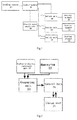
- Figure 1 illustrates an electronic cigarette control circuit which is utilized for controlling an electronic cigarette, wherein the control circuit comprises at least one airflow sensor 10, a control module 20, at least two heating components 30, at least two switch units 40 and an electric power supply module 50.
- the at least two switch units 40, the airflow sensor 10 and the electric power supply module 50 are all connected to the control module 20 respectively.
- Each of the switch units 40 is connected between each of the heating components 30 and the electric power supply module 50 respectively.
- the airflow sensor 10 is used for collecting an airflow signal of each instance of inhalation into the electronic cigarette and for transmitting the airflow signal to the control module 20, and the control module20 is used for comparing a value of the airflow signal of each instance with a predetermined value and transmitting a conduction signal to one of the switch units 40 selectively according to a comparison result,; the selected switch unit 40 is turned on when the conduction signal is received to allow the corresponding heating component 30 to heat up, and the heating element30 is used for heating up cigarette oil in corresponding oil-storage component to atomize the cigarette oil.
- quantity of the switch units and the heating elements is three respectively. Number of the airflow sensor is one.
- the switch units 40 can be selected as commonly used switch circuits.
- multiple of the switch units 40 can be turned on simultaneously, or all of the switch units 40 can be turned on simultaneously as well to realize the object of automatically generating multiple tastes and changing the amount of smoke.
- Resistance values of the heating components can be identical or different, and can be set up as required with no limitation in this embodiment. For instance, in the present embodiment, the resistance values of the heating components are different, and are corresponding to different oil-storage components.
- the electronic cigarette control circuit enables users to control the heating components 30 in the corresponding oil-storage components to heat up by changing the exerted smoking strength of each instance, so as to correspondingly change the smoking taste, and the smoke amount can be changed on the basis of the exerted smoking strength as well to make the electronics cigarette much like a real cigarette. Additionally, it realizes a situation that users with different smoking tastes and exerted smoking strength can share a same electronic cigarette together; thus it is more convenient in the case of travel or other situations, especially for a family with multiple smokers.
- the control module 20 is a microprocessor.
- Figure 2 illustrates that the microprocessor comprises an analog-to-digital conversion unit 21, a memory unit 22, a comparing unit 23 and a control unit 24.
- the comparing unit 23 is connected to the airflow sensor 10 and the control unit 24 respectively, and the control unit 24 is connected to the at least two switch units 40 respectively;
- the memory unit 22 is connected to the comparing unit 23;
- the analog-to-digital conversion unit 21 is connected to the comparing unit 23.
- the analog-to-digital conversion unit 21 is utilized to convert analog signals to digital signals, and the memory unit 22 is utilized to store at least two predetermined values; the comparing unit 23 is used to compare the peak value of the airflow signal with each of the predetermined values, then select a maximum predetermined value from the at least two predetermined values, and the maximum predetermined value should be less than the peak value of the airflow signal; the comparing unit 23 then transmits a signal of the comparison result to the control unit 24 on the basis of the maximum predetermined value; according to the signal of comparison result, the control unit 24 transmits the conduction signal to one switch unit 40 of the at least two switch units 40.
- the microprocessor can further comprise a timing unit 25, and the timing unit 25 is connected to the control unit 24; the control unit 24 transmits a trigger signal to the timing unit 25 when the control unit 24 transmits the conduction signal to the switch units 40.
- the timing unit 25 receives the trigger signal and begins to time, and transmits a feedback signal to the control unit 24 after timing a predetermined time; according to the feedback signal, the control unit 24 transmits a close signal to the one switch unit 40 that is turned on; upon receiving the close signal, the switch unit 40 is switched off to stop the corresponding heating components 30 from heating up.
- the timing unit 25 controls conduction time of the switching unit 40 in response to each smoking time by setting a predetermined time, so as to more accurately control the amount of smoke during each smoking. Further, after the predetermined time, the switch units 24 are automatically closed, saving smoke oil and electric energy avoiding unnecessary waste.
- the comparing unit 23 receives the other airflow signal in the predetermined time, and generates a next comparison result signal and then transmits the next comparison result signal to the control unit 24, namely when the time interval of receiving the two airflow signals is less than the predetermined time set in the time unit 25:
- the control unit 24 transmits a triggering signal to the time unit 25; the time unit 25 resets after receiving this triggering signal, and begins to timing again, and then transmits the feedback signal to the control unit 24; the control unit 24 transmits a close signal to the switch unit 40 that is turned on to switch off.
- the control unit 24 transmits a close signal to the switch units 40 that is turned on to switch off, and simultaneously transmits a conduction signal to switch units which are corresponding to the next comparison result signal to make them conducted. Further, a triggering signal is transmitted to the time unit 25, the time unit 25 resets and times again, the feedback signal is transmitted to the control unit 24 after the predetermined time, then the control unit 24 transmits a close signal to the switch units 40 which are in a conducting state to switch off the switch units 40.
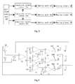
- the control module 20 comprises at least two comparison control circuits 20a, an input terminal of each of the comparison control circuits 20a is connected to the airflow sensor 10 respectively; an output terminal of each of the comparison control circuits 20a is connected to one of the switch units 40 respectively, the at least two predetermined values are set to increase successively by the at least two comparison control circuits 20a, and the airflow signal triggers the comparison control circuits 20a whose predetermined values are smaller than the value of the airflow signal.
- an output terminal of this triggered comparison control circuit 20a outputs the conduction signal.
- comparison control circuits 20a When more than one of comparison control circuits 20a are triggered, all triggered comparison control circuits 20a are arranged in an order of the predetermined values; between each two adjacent comparison control circuits 20a, the comparison control circuit 20a with a larger predetermined value suppresses and closes the comparison control circuit 20a with a smaller predetermined value, and the comparison control circuits 20a with the maximum predetermined value outputs the conduction signal.
- each of the comparison control circuits 20a comprises a first comparison control circuit U2 and a second comparison control circuit U3.
- the first comparison control circuit U2 and the second comparison control circuit U3 are both provided with a comparative voltage input terminal, a reference voltage terminal and an output terminal.
- the working principle of the first comparison control circuit U2 and the second comparison control circuit U3 is that the output terminal outputs a voltage when a voltage of the comparative voltage input terminal is higher than a voltage of the reference voltage terminal.
- the first comparison control circuit U2 and the second comparison control circuit U3 are both operational amplifiers.
- One divider resistance is placed at a comparative voltage input terminal and a reference voltage terminal of each operational amplifiers. Understandably, the first comparison control circuit U2 and the second comparison control circuit U3 can be realized by other methods, for instance, chips and single chip microcomputers, etc.
- a comparative voltage input terminal of the first comparison control circuit U2 is connected to the airflow sensor 10, and one of the predetermined values is taken as a reference voltage by a reference voltage terminal of the first comparison control circuit U2.
- the output terminal of the first comparison control circuit U2 with a larger predetermined value between the two adjacent comparison control circuits 20a is connected to a reference voltage terminal of the second comparison control circuit U3 which is corresponding to the first comparison control circuit U2 that has a smaller predetermined value.
- "adjacent” herein refers to the adjacent of the at least two comparison control circuit 20a, which are arranged by values of the predetermined values.
- a comparative voltage input terminal of the second comparison control circuit U3 is connected to an output terminal of the first comparison control circuit U2, the reference voltage terminal of the second comparison control circuit U3 is connected to the divider resistance, and then connected to ground.
- the first comparison control circuit U2 compares the value of the airflow signal with each of the predetermined values, and a second voltage is transmitted to the comparative voltage input terminal of the second comparison control circuit U3 by the output terminal of the first comparison control circuit U2 which has a predetermined value less than the value of the airflow signal.
- an output terminal of the second comparison control circuit U3 When only one predetermined value of the first comparison control circuits U2 is smaller than the value of the air flow, an output terminal of the second comparison control circuit U3 outputs the conduction signal to a corresponding switch unit 40.
- the second comparison control circuit U3 which is responding to the first comparison control circuits U2 that has the maximum predetermined value outputs the conduction signal to a corresponding switch unit 40
- second comparison control circuits U3 which are responding to the rest first comparison control circuits U2 are closed by inhibition from the second voltage which are outputted by the output terminals of the first comparison control circuits U2 which are connected to the reference voltage terminals of the above second comparison control circuits U3.
- the control module 20 further comprises at least two time delay units 200, and each of the time delay units 200 is connected between each of the second comparison control circuits U3 and the corresponding switch units 40 respectively.
- the time delay units 200 are used to continuously provide the conduction signal to the corresponding switch units 40 within the predetermined time so that the corresponding switch units 40 are continuously turned on within the predetermined time. After this predetermined time, the corresponding switch units 40 is switched off automatically, and the corresponding heating components 30 which are connected to the switch units 40 stop heating up.
- the electronic cigarette control circuit further comprises an amplify unit U1 which is connected between the airflow sensor 10 and each of the first comparison control circuits U2.
- the amplify unit U1 is utilized to amplify the airflow signal which is detected by the airflow sensor 10, and then transmits the amplified airflow signal to each of the first comparison control circuits U2.
- the amplify unit U1 can be applied by an operational amplifier, and naturally it is also possible to adopt other conventional amplification circuits as well.
- the switch units 40 are MOS tubes and other common switching circuits which are formed by a triode and so on.
- the present invention further provides an electronic cigarette, wherein the electronic cigarette comprises the electronic cigarette control circuit provided by any one of the embodiments above mention.
- the electronic cigarette comprises at least two oil-storage components which are utilized to store different oil, and each of heating elements 30 is placed in each of the oil-storage elements respectively, and the electronic cigarette merely has one airflow sensor 10.
- the airflow sensor 10 is placed at the air inlet of the electronic cigarette.
- the electronic cigarette comprises at least two atomizers, and the at least two oil-storage components are placed in the at least two atomizers respectively.
- the quantity of the airflow sensor is at least two, preferably, three.
- Each of the airflow sensors 10 is set up in different working pressure sections. The airflow sensor 10 transmits an airflow signal to the control module 20 when the airflow signal around the working pressure sections is detected.
- the present invention provides a control method of an electronic cigarette, as shown in Fig. 4 , the first embodiment of the control method comprises the following steps:
- the airflow signal is a voltage signal produced by the airflow sensor 10 on the basis of the change of air flow
- the predetermined values are the voltage values which are set in response to the airflow signal.
- step S2 further comprises the following steps:
- the control unit 24 transmits a trigger signal to a timing unit 25 of the microprocessor when the control unit 24 transmits the conduction signal to one switch unit 40 of the at least two switch units 40.
- the timing unit 25 receives the trigger signal and begins to time, and transmits a feedback signal to the control unit 24 after timing a predetermined time; according to the feedback signal, the control unit 24 transmits a close signal to the switch unit 40 that is turned on; after receiving the close signal, the switch unit 40 switches off to stop the heating components 30 from heating up.
- step S2 further comprises following steps:
- an output terminal of the second comparison control circuit U3 of the comparison control circuits 20a outputs the conduction signal to a corresponding switch unit 40.
- the second comparison control circuit U3 which is corresponding to the first comparison control circuits U2 that has the comparative the maximum predetermined value outputs the conduction signal to a control terminal of a corresponding switch unit 40
- second comparison control circuits U3 which are corresponding to the rest first comparison control circuits U2 are closed by inhibition from the second voltage which are outputted by the output terminals of the first comparison control circuits U2 which are connected to the reference voltage terminals of the second comparison control circuits U3.
- the comparison control circuits 20a first transmit the conduction signal to time delay units 200, and upon receiving the conduction signal, the time delay units 200 continuously provide the conduction signal to the switch units 40 within the predetermined time.
- the switch units 40 are continuously turned on in the predetermined time. When the switch units 40 do not receive the conduction signal, they are switched off automatically.
- control module 20 by providing the control module 20 on the basis of the airflow signal, which is collected by the airflow sensor 10, to control corresponding one or more than one switch units to be conducted, it is possible to enable the heating elements 30 to heat the cigarette oil in corresponding oil-storage elements, thus, to achieve the technical objects of enhanced user experience by allowing changes to smoking taste and amount on the basis of exerted smoking strength; Additionally, the control module 20 can further control a predetermined time of the heating of the heating elements 30, thus to precisely control smoke amount of each instance of inhalation. According to various smokers smoking habits and preferences, the smoke amount of each instance of inhalation during smoking is more reasonably configured to achieve the best effect. Moreover, the electronic cigarette saves smoke oil and electricity, and terminates the electronic cigarette's working condition when users forget to turn off the electronic cigarette.
Landscapes
- Control Of Resistance Heating (AREA)
- Manufacturing Of Cigar And Cigarette Tobacco (AREA)
- Disinfection, Sterilisation Or Deodorisation Of Air (AREA)
Abstract
Description
- The present application relates to the technical field of electronic products, and more particularly, relates to electronic cigarette control circuit, electronic cigarette, and control method for electronic cigarette.
- Normally, An electronic cigarette is comprised of an atomization assembly and a battery rod. The atomization assembly comprises an oil-storage component for storing oil and a heating component for heating oil. When the heating component heats, the oil in corresponding oil-storage component is atomized into smoke, then the smoke is exported from a nozzle to achieve the effect of smoking. The battery rod contains an air pressure driving switch and a power supply module. In response to the pressure produced by air flow when smoking, the power supply module is triggered to supply power to the heating component, then the heating element heats up the oil to generate smoke.
- In the above technique, whatever smoking strength is used by users when smoking, the amount and taste of the smoke produced by the atomization assembly are the same. Therefore, users cannot experience a change of the amount of the smoke on the basis of a change of the exerted smoking strength when smoking a real cigarette, the taste remains the same, and cannot be changed by smoking habits of smokers, thus requirements of users cannot be satisfied by the prior art.
- The objective of the present application is to provide an improved electronic cigarette control circuit, electronic cigarette, and control method for electronic cigarette, aiming at the drawbacks in the prior art that, it is difficult to achieve an experience that the amount and taste of smoke can be changed on the basis of the exerted smoking strength which can be satisfied when smoking a real cigarette.
- In accordance with one aspect of the present application, the present application provides an electronic cigarette control circuit which is utilized for controlling an electronic cigarette, wherein, the control circuit comprises at least one airflow sensor, a control module, at least two switch units, and corresponding at least two heating components, and one of the at least two heating components is connected to one of the least two switch units correspondingly; the at least two switch units and the at least one airflow sensor are connected to the control module respectively;
- The airflow sensor is used for collecting an airflow signal of each instance of inhalation of the electronic cigarette and for transmitting the airflow signal to the control module; the control module is used for comparing the value of the airflow signal of each instance with a predetermined value and for selecting, on the basis of a comparison result, to transmit a conduction signal to at least one switch unit of the at least two switch units; the at least one switch unit is turned on upon receiving the conduction signal to allow corresponding at least one heating component to heat up; the at least one heating component is used for heating up cigarette oil in corresponding at least one oil-storage component to atomize the cigarette oil.
- Advantageously, in the electronic cigarette control circuit of the present application, the electronic cigarette control circuit further comprises an electric power supply module, and the electric power supply module is connected to the control module and each of the at least two switch units respectively; the electric power supply module is used to provide electric power to the control module, each of the at least two switch units and each of the at least two heating components.
- Advantageously, in the electronic cigarette control circuit of the present application, the control module is a microprocessor, and the microprocessor comprises a memory unit, a comparing unit and a control unit; the comparing unit is connected to the airflow sensor and the control unit respectively, and the control unit is connected to the at least two switch units respectively; the memory unit is connected to the comparing unit;
- the memory unit is used to store at least two predetermined values, and the comparing unit is used to compare the peak value of the airflow signal with each of the predetermined values, then select a maximum predetermined value from the at least two predetermined values, and the maximum predetermined value should be less than the peak value of the airflow signal; the comparing unit then transmits a signal of the comparison result to the control unit on the basis of the maximum predetermined value; according to the signal of comparison result, the control unit transmits the conduction signal to at least one switch unit of the at least two switch units.
- Advantageously, in the electronic cigarette control circuit of the present application, the microprocessor further comprises a timing unit; the timing unit is connected to the control unit, and the control unit transmits a trigger signal to the timing unit when the control unit transmits the conduction signal; the timing unit receives the trigger signal and begins to time, and transmits a feedback signal to the control unit after timing a predetermined time; according to the feedback signal, the control unit transmits a close signal to the at least one switch unit which is in a conducting state; upon receiving the close signal, the at least one switch unit, is switched off to stop the corresponding at least one heating component from heating up.
- Advantageously, in the electronic cigarette control circuit of the present application, the control module comprises at least two comparison control circuits, and an input terminal of each of the comparison control circuits is correspondingly connected to the airflow sensor; an output terminal of each of the comparison control circuits is correspondingly connected to one of the at least two switch units, and the predetermined values are set to increase successively by the at least two comparison control circuits, and then the airflow signal triggers the comparison control circuits whose predetermined values are smaller than the value of the airflow signal;
- when one of the comparison control circuits is triggered, an output terminal of this triggered comparison control circuits outputs the conduction signal;
- when more than one of the comparison control circuits are triggered, all the triggered comparison control circuits are arranged in an order of the predetermined values; between each two adjacent comparison control circuits, the comparison control circuit with a larger predetermined value suppresses and closes the comparison control circuit with a smaller predetermined value, and the comparison control circuit with the maximum predetermined value outputs the conduction signal.
- Advantageously, in the electronic cigarette control circuit of the present application, each of the comparison control circuits comprises a first comparison control circuit and a second comparison control circuit, and a comparative voltage input terminal of the first comparison control circuit is connected to the airflow sensor; one of the predetermined values is taken as a reference voltage by a reference voltage terminal of the first comparison control circuit, and an output terminal of the first comparison control circuit with a larger predetermined value between the two adjacent comparison control circuits is connected to a reference voltage terminal of the second comparison control circuit which is corresponding to the first comparison control circuit with a smaller predetermined value; comparative voltage input terminal of the second comparison control circuit is connected to the output terminal of the first comparison control circuit; the first comparison control circuit is used to compare the value of the airflow signal with each of the predetermined values, and a second voltage is transmitted to the comparative voltage input terminal of the second comparison control circuit by an output terminal of the first comparison control circuit with a predetermined value less than the value of the airflow signal.
- Advantageously, in the electronic cigarette control circuit of the present application, the control module further comprises at least two time delay units, and the at least two time delay units are connected between the at least two switch units and the second comparison control circuits respectively; the time delay units are used to continuously provide the conduction signal to the at least two switch units within the predetermined time for the at least two switch units to be continuously turned on within the predetermined time.
- Advantageously, in the electronic cigarette control circuit of the present application, the electronic cigarette control circuit further comprises an amplify unit which is utilized to amplify the airflow signal, the amplify unit is connected between the airflow sensor and the control module.
- Advantageously, in the electronic cigarette control circuit of the present application, the switch units are MOS tubes.
- In accordance with another aspect of the present application, an electronic cigarette contains the electronic cigarette control circuit provided by the present application.
- Advantageously, in the electronic cigarette of the present application, the electronic cigarette comprises at least two oil-storage components which are utilized to store different oil, and each of the heating components is placed in each of the oil-storage components respectively.
- Advantageously, in the electronic cigarette of the present application, the electronic cigarette comprises at least two atomizers, and the at least two oil-storage components are placed in the at least two atomizers respectively.
- Advantageously, in the electronic cigarette of the present application, wherein the electronic cigarette comprises an atomizer, and the at least two oil-storage elements are placed in the atomizer.
- Advantageously, in the electronic cigarette of the present application, wherein the electronic cigarette comprises at least two airflow sensors, and each of the airflow sensors is set up in different working pressure sections, and transmits an airflow signal to the control module upon detecting the airflow signal in the working pressure section.
- In accordance with further aspect of the present application, the present invention also provides a control method of an electronic cigarette, wherein, the control method comprises the following steps:
- S1: an airflow sensor collects an airflow signal of each instance of inhalation of the electronic cigarette and transmits the airflow signal to a control module;
- S2: the control module compares a value of the airflow signal of each instance with a predetermined value and selects, on the basis of a comparison result, to transmit a conduction signal to at least one switch unit of the at least two switch units; the at least one switch unit is turned on to allow the corresponding heating components to heat up upon receiving the conduction signal.
- Advantageously, in the control method of an electronic cigarette of the present application, the step S2 further comprises the following steps:
- S2.1: the control module is a microprocessor, which sets up at least two predetermined values being defined in the memory unit of the microprocessor;
- S2.2: a comparing unit of the microprocessor compares the peak value of the airflow signal with each of the predetermined values respectively, and then selects a maximum predetermined value from the at least two predetermined values where the maximum predetermined value should be less than the peak value of the airflow signal, and the comparing unit then transmits a signal of the comparison result to a control unit of the microprocessor on the basis of the maximum predetermined value;
- S2.3: the control unit selects, on the basis of the comparison result, to transmit a conduction signal to a switch unit of the at least two switch units; the switch unit is turned on to allow the corresponding heating components to heat up upon receiving the conduction signal.
- Advantageously, in the control method of an electronic cigarette of the present application, in S2.3, wherein the control unit transmits a trigger signal to a timing unit of the microprocessor when the control unit transmits the conduction signal to one switch unit of the at least two switch units; the timing unit receives the trigger signal and begins to time, and transmits a feedback signal to the control unit after timing a predetermined time; according to the feedback signal, the control unit transmits a close signal to the switch unit which is turned on; upon receiving the close signal, the switch unit switches off to stop the heating components from heating up.
- Advantageously, in the control method of an electronic cigarette of the present application, the step S2 further comprises the following steps:
- The predetermined values are set to increase successively in each comparison control circuit of the control module, and the airflow signal triggers the comparison control circuits whose predetermined values are smaller than the value of the airflow signal;
- when one of the comparison control circuits is triggered, an output terminal of this triggered comparison control circuits outputs the conduction signal to the corresponding switch unit;
- when more that one of comparison control circuits are triggered, all triggered comparison control circuits are arranged in an order of the predetermined values, and the predetermined values are compared between each two adjacent comparison control circuits; one of the two adjacent comparison control circuits with a larger predetermined value suppresses and closes s another comparison control circuit with a smaller predetermined value, and one of the triggered comparison control circuit with the maximum predetermined value outputs the conduction signal.
- Advantageously, in the control method of an electronic cigarette of the present application, in the step S2, the comparison control circuits first transmit the conduction signal to time delay units, and upon receiving the conduction signal, the time delay units continuously provide the conduction signal to the at least two switch units within the predetermined time.
- With application of the electronic cigarette control circuit, the electronic cigarette, and the control method for the electronic cigarette, the following advantages can be achieved: by providing the control module on the basis of the airflow signal, which is collected by the airflow sensor, to control corresponding one or more than one switch units to be turned on , it is possible to enable the heating components which are corresponding to the switch units to heat up the cigarette oil in different oil-storage components , thus, to achieve the technical objections of enhanced user experience by allowing changes to smoking taste and amount on the basis of the exerted smoking strength; additionally, it realizes a situation that users who has different smoking taste and exerted smoking strength can share a same electronic cigarette together, thus, it is more convenient in the case of travel or other situations that it is not convenient to bring too many items with smokers, especially convenient for a family which has multiple smokers.
- For a better understanding of the aforementioned embodiments of the invention as well as additional embodiments thereof, reference should be made to the Description of Embodiments below, in conjunction with the following drawings in which like reference numerals refer to corresponding parts throughout the figures.
-
Fig. 1 is a principle block diagram of an electronic cigarette control circuit provided by a first embodiment of the present application; -
Fig. 2 is a principle block diagram of a control module provided by a first embodiment of the present application; -
Fig. 3 is a principle block diagram of an electronic cigarette control circuit provided by a second embodiment of the present application; -
Fig.4 is a circuit schematic diagramof an electronic cigarette control circuit provided by a second embodiment of the present application; -
Fig. 5 is a flow diagram of a control method of an electronic cigarette provided by a first embodiment of the present application -
Fig. 6 is a detailed flow diagram of astep 2 in a control method of an electronic cigarette provided by a first embodiment of the present application. - In order to solve the drawbacks in the prior art that, it is difficult to achieve an experience that the amount and taste of smoke can be changed on the basis of the exerted smoking strength which can be satisfied when smoking a real cigarette, creativity of the present invention is that, comparing airflow signals produced by strongly and lightly exerted smoking with predetermined values, switching corresponding switch units which are connected to heating elements, then controlling cigarette oil in different oil-storage elements which are corresponding to the switch units to achieve objects of changing smoking taste and amount on the basis of exerted smoking strength.
- The example embodiments of the present application will be further described with reference to the accompanying drawings in order to have a clear understanding of the technical features, purposes and effects of the present invention. Obviously, the following example embodiments are only parts of the embodiments of the present application.
- Refer to
Fig. 1, Figure 1 illustrates an electronic cigarette control circuit which is utilized for controlling an electronic cigarette, wherein the control circuit comprises at least oneairflow sensor 10, acontrol module 20, at least twoheating components 30, at least twoswitch units 40 and an electricpower supply module 50. The at least twoswitch units 40, theairflow sensor 10 and the electricpower supply module 50 are all connected to thecontrol module 20 respectively. Each of theswitch units 40 is connected between each of theheating components 30 and the electricpower supply module 50 respectively. - The
airflow sensor 10 is used for collecting an airflow signal of each instance of inhalation into the electronic cigarette and for transmitting the airflow signal to thecontrol module 20, and the control module20 is used for comparing a value of the airflow signal of each instance with a predetermined value and transmitting a conduction signal to one of theswitch units 40 selectively according to a comparison result,; theselected switch unit 40 is turned on when the conduction signal is received to allow thecorresponding heating component 30 to heat up, and the heating element30 is used for heating up cigarette oil in corresponding oil-storage component to atomize the cigarette oil. In the present embodiment, quantity of the switch units and the heating elements is three respectively. Number of the airflow sensor is one. Theswitch units 40 can be selected as commonly used switch circuits. Certainly, in other embodiments, multiple of theswitch units 40 can be turned on simultaneously, or all of theswitch units 40 can be turned on simultaneously as well to realize the object of automatically generating multiple tastes and changing the amount of smoke. Resistance values of the heating components can be identical or different, and can be set up as required with no limitation in this embodiment. For instance, in the present embodiment, the resistance values of the heating components are different, and are corresponding to different oil-storage components. - The electronic cigarette control circuit enables users to control the
heating components 30 in the corresponding oil-storage components to heat up by changing the exerted smoking strength of each instance, so as to correspondingly change the smoking taste, and the smoke amount can be changed on the basis of the exerted smoking strength as well to make the electronics cigarette much like a real cigarette. Additionally, it realizes a situation that users with different smoking tastes and exerted smoking strength can share a same electronic cigarette together; thus it is more convenient in the case of travel or other situations, especially for a family with multiple smokers. - In a first embodiment, the
control module 20 is a microprocessor.Figure 2 illustrates that the microprocessor comprises an analog-to-digital conversion unit 21, amemory unit 22, a comparingunit 23 and acontrol unit 24. The comparingunit 23 is connected to theairflow sensor 10 and thecontrol unit 24 respectively, and thecontrol unit 24 is connected to the at least twoswitch units 40 respectively; thememory unit 22 is connected to the comparingunit 23; the analog-to-digital conversion unit 21 is connected to the comparingunit 23. - The analog-to-digital conversion unit 21 is utilized to convert analog signals to digital signals, and the
memory unit 22 is utilized to store at least two predetermined values; the comparingunit 23 is used to compare the peak value of the airflow signal with each of the predetermined values, then select a maximum predetermined value from the at least two predetermined values, and the maximum predetermined value should be less than the peak value of the airflow signal; the comparingunit 23 then transmits a signal of the comparison result to thecontrol unit 24 on the basis of the maximum predetermined value; according to the signal of comparison result, thecontrol unit 24 transmits the conduction signal to oneswitch unit 40 of the at least twoswitch units 40. - Understandably, the microprocessor can further comprise a
timing unit 25, and thetiming unit 25 is connected to thecontrol unit 24; thecontrol unit 24 transmits a trigger signal to thetiming unit 25 when thecontrol unit 24 transmits the conduction signal to theswitch units 40. Thetiming unit 25 receives the trigger signal and begins to time, and transmits a feedback signal to thecontrol unit 24 after timing a predetermined time; according to the feedback signal, thecontrol unit 24 transmits a close signal to the oneswitch unit 40 that is turned on; upon receiving the close signal, theswitch unit 40 is switched off to stop thecorresponding heating components 30 from heating up. - The
timing unit 25 controls conduction time of the switchingunit 40 in response to each smoking time by setting a predetermined time, so as to more accurately control the amount of smoke during each smoking. Further, after the predetermined time, theswitch units 24 are automatically closed, saving smoke oil and electric energy avoiding unnecessary waste. - When the comparing
unit 23 receives the other airflow signal in the predetermined time, and generates a next comparison result signal and then transmits the next comparison result signal to thecontrol unit 24, namely when the time interval of receiving the two airflow signals is less than the predetermined time set in the time unit 25: - If the next comparison result signal is identical with a previous comparison result, the
control unit 24 transmits a triggering signal to thetime unit 25; thetime unit 25 resets after receiving this triggering signal, and begins to timing again, and then transmits the feedback signal to thecontrol unit 24; thecontrol unit 24 transmits a close signal to theswitch unit 40 that is turned on to switch off. - If the next comparison result signal is different with a previous comparison result, the
control unit 24 transmits a close signal to theswitch units 40 that is turned on to switch off, and simultaneously transmits a conduction signal to switch units which are corresponding to the next comparison result signal to make them conducted. Further, a triggering signal is transmitted to thetime unit 25, thetime unit 25 resets and times again, the feedback signal is transmitted to thecontrol unit 24 after the predetermined time, then thecontrol unit 24 transmits a close signal to theswitch units 40 which are in a conducting state to switch off theswitch units 40. - In a second embodiment, as shown in
Fig. 4 , thecontrol module 20 comprises at least twocomparison control circuits 20a, an input terminal of each of thecomparison control circuits 20a is connected to theairflow sensor 10 respectively; an output terminal of each of thecomparison control circuits 20a is connected to one of theswitch units 40 respectively, the at least two predetermined values are set to increase successively by the at least twocomparison control circuits 20a, and the airflow signal triggers thecomparison control circuits 20a whose predetermined values are smaller than the value of the airflow signal. When only one of thecomparison control circuits 20a is triggered, an output terminal of this triggeredcomparison control circuit 20a outputs the conduction signal. When more than one ofcomparison control circuits 20a are triggered, all triggeredcomparison control circuits 20a are arranged in an order of the predetermined values; between each two adjacentcomparison control circuits 20a, thecomparison control circuit 20a with a larger predetermined value suppresses and closes thecomparison control circuit 20a with a smaller predetermined value, and thecomparison control circuits 20a with the maximum predetermined value outputs the conduction signal. - Further, as shown in
Fig. 4 , each of thecomparison control circuits 20a comprises a first comparison control circuit U2 and a second comparison control circuit U3. The first comparison control circuit U2 and the second comparison control circuit U3 are both provided with a comparative voltage input terminal, a reference voltage terminal and an output terminal. The working principle of the first comparison control circuit U2 and the second comparison control circuit U3 is that the output terminal outputs a voltage when a voltage of the comparative voltage input terminal is higher than a voltage of the reference voltage terminal. The first comparison control circuit U2 and the second comparison control circuit U3 are both operational amplifiers. One divider resistance is placed at a comparative voltage input terminal and a reference voltage terminal of each operational amplifiers. Understandably, the first comparison control circuit U2 and the second comparison control circuit U3 can be realized by other methods, for instance, chips and single chip microcomputers, etc. - A comparative voltage input terminal of the first comparison control circuit U2 is connected to the
airflow sensor 10, and one of the predetermined values is taken as a reference voltage by a reference voltage terminal of the first comparison control circuit U2. The output terminal of the first comparison control circuit U2 with a larger predetermined value between the two adjacentcomparison control circuits 20a is connected to a reference voltage terminal of the second comparison control circuit U3 which is corresponding to the first comparison control circuit U2 that has a smaller predetermined value. In the present invention, "adjacent" herein refers to the adjacent of the at least twocomparison control circuit 20a, which are arranged by values of the predetermined values. A comparative voltage input terminal of the second comparison control circuit U3 is connected to an output terminal of the first comparison control circuit U2, the reference voltage terminal of the second comparison control circuit U3 is connected to the divider resistance, and then connected to ground. The first comparison control circuit U2 compares the value of the airflow signal with each of the predetermined values, and a second voltage is transmitted to the comparative voltage input terminal of the second comparison control circuit U3 by the output terminal of the first comparison control circuit U2 which has a predetermined value less than the value of the airflow signal. - When only one predetermined value of the first comparison control circuits U2 is smaller than the value of the air flow, an output terminal of the second comparison control circuit U3 outputs the conduction signal to a
corresponding switch unit 40. When more than one predetermined values of the first comparison control circuits U2 are smaller than the value of the air flow, the second comparison control circuit U3 which is responding to the first comparison control circuits U2 that has the maximum predetermined value outputs the conduction signal to acorresponding switch unit 40, second comparison control circuits U3 which are responding to the rest first comparison control circuits U2 are closed by inhibition from the second voltage which are outputted by the output terminals of the first comparison control circuits U2 which are connected to the reference voltage terminals of the above second comparison control circuits U3. - As an optimization scheme of the present embodiment, the
control module 20 further comprises at least twotime delay units 200, and each of thetime delay units 200 is connected between each of the second comparison control circuits U3 and thecorresponding switch units 40 respectively. Thetime delay units 200 are used to continuously provide the conduction signal to thecorresponding switch units 40 within the predetermined time so that thecorresponding switch units 40 are continuously turned on within the predetermined time. After this predetermined time, thecorresponding switch units 40 is switched off automatically, and thecorresponding heating components 30 which are connected to theswitch units 40 stop heating up. - Preferably, the electronic cigarette control circuit further comprises an amplify unit U1 which is connected between the
airflow sensor 10 and each of the first comparison control circuits U2. The amplify unit U1 is utilized to amplify the airflow signal which is detected by theairflow sensor 10, and then transmits the amplified airflow signal to each of the first comparison control circuits U2. The amplify unit U1 can be applied by an operational amplifier, and naturally it is also possible to adopt other conventional amplification circuits as well. - In the present embodiment, the
switch units 40 are MOS tubes and other common switching circuits which are formed by a triode and so on. - The present invention further provides an electronic cigarette, wherein the electronic cigarette comprises the electronic cigarette control circuit provided by any one of the embodiments above mention. The electronic cigarette comprises at least two oil-storage components which are utilized to store different oil, and each of
heating elements 30 is placed in each of the oil-storage elements respectively, and the electronic cigarette merely has oneairflow sensor 10. Theairflow sensor 10 is placed at the air inlet of the electronic cigarette. - Alternatively, the electronic cigarette comprises at least two atomizers, and the at least two oil-storage components are placed in the at least two atomizers respectively. Meanwhile, the quantity of the airflow sensor is at least two, preferably, three. Each of the
airflow sensors 10 is set up in different working pressure sections. Theairflow sensor 10 transmits an airflow signal to thecontrol module 20 when the airflow signal around the working pressure sections is detected. - Furthermore, the present invention provides a control method of an electronic cigarette, as shown in
Fig. 4 , the first embodiment of the control method comprises the following steps: - S1: an
airflow sensor 10 collects an airflow signal of each instance of inhalation of the electronic cigarette and transmits the airflow signal to acontrol module 20; - S2: the
control module 20 compares the value of the airflow signal of each instance with a predetermined value and selects, on the basis of a comparison result, to transmit a conduction signal to at least oneswitch unit 40 of the at least twoswitch units 40; the at least oneswitch unit 40, is turned on to allow thecorresponding heating components 30 to heat up upon receiving the conduction signal. - In this embodiment of the present invention, the airflow signal is a voltage signal produced by the
airflow sensor 10 on the basis of the change of air flow, and the predetermined values are the voltage values which are set in response to the airflow signal. - As shown in
Fig.4 , step S2 further comprises the following steps: - S2.1: the
control module 20 is a microprocessor, and an analog-to-digital conversion unit 21 of the microprocessor converts an airflow signal from an analog signal into a digital signal, and the microprocessor presets at least two predetermined values, and then stores the at least two predetermined values in thememory unit 22 of the microprocessor ; - S2.2: a comparing
unit 23 of the microprocessor compares the peak value of the airflow signal which is changed into a digital signal with each of the predetermined values, and then selects a maximum predetermined value from the at least two predetermined values, and the maximum predetermined value should be less than the peak value of the airflow signal; the comparingunit 23 then transmits a signal of a comparison result to acontrol unit 24 of the microprocessor on the basis of the maximum predetermined value; - S2.3: the
control unit 24 selects, on the basis of the signal of the comparison result, to transmit a conduction signal to oneswitch unit 40 of the at least twoswitch units 40; the oneswitch unit 40 receiving the conduction signal is turned on to allow thecorresponding heating components 30 to heat up. - During the step S2.3, the
control unit 24 transmits a trigger signal to atiming unit 25 of the microprocessor when thecontrol unit 24 transmits the conduction signal to oneswitch unit 40 of the at least twoswitch units 40. Thetiming unit 25 receives the trigger signal and begins to time, and transmits a feedback signal to thecontrol unit 24 after timing a predetermined time; according to the feedback signal, thecontrol unit 24 transmits a close signal to theswitch unit 40 that is turned on; after receiving the close signal, theswitch unit 40 switches off to stop theheating components 30 from heating up. - Alternatively, when the
control module 20 of the second embodiment is applied, the step S2 further comprises following steps: - the predetermined values are set to increase successively in each of
comparison control circuits 20a of thecontrol module 20, and the airflow signal triggers thecomparison control circuits 20a whose predetermined values are smaller than the value of the airflow signal; - when one of the
comparison control circuits 20a is triggered, an output terminal of this triggeredcomparison control circuits 20a outputs the conduction signal to thecorresponding switch units 40 for the corresponding oil storage component to heat up; - when more that one of
comparison control circuits 20a are triggered, all triggeredcomparison control circuits 20a are arranged in an order of the predetermined values, and the predetermined values are compared between each two adjacentcomparison control circuits 20a; one of the two adjacentcomparison control circuits 20a with a larger predetermined value suppresses and closes anothercomparison control circuit 20a with a smaller predetermined value, and one of the triggeredcomparison control circuits 20a with the maximum predetermined value outputs the conduction signal. Thecomparison control circuit 20a with the maximum predetermined value outputs the conduction signal to the control terminal of theswitch units 40, and the rest ofcomparison control circuits 20a are closed by inhabition ofcomparison control circuits 20a that has higher and similar predetermined values respectively. - Further, when only one predetermined value of the first comparison control circuits U2 of the
comparison control circuits 20a is smaller than the value of the air flow, an output terminal of the second comparison control circuit U3 of thecomparison control circuits 20a outputs the conduction signal to acorresponding switch unit 40. When more than one predetermined values of the first comparison control circuits U2 are smaller than the value of the air flow, the second comparison control circuit U3 which is corresponding to the first comparison control circuits U2 that has the comparative the maximum predetermined value outputs the conduction signal to a control terminal of acorresponding switch unit 40, second comparison control circuits U3 which are corresponding to the rest first comparison control circuits U2 are closed by inhibition from the second voltage which are outputted by the output terminals of the first comparison control circuits U2 which are connected to the reference voltage terminals of the second comparison control circuits U3.
in the step S2.3, thecomparison control circuits 20a first transmit the conduction signal totime delay units 200, and upon receiving the conduction signal, thetime delay units 200 continuously provide the conduction signal to theswitch units 40 within the predetermined time. Theswitch units 40 are continuously turned on in the predetermined time. When theswitch units 40 do not receive the conduction signal, they are switched off automatically. - In general, by providing the
control module 20 on the basis of the airflow signal, which is collected by theairflow sensor 10, to control corresponding one or more than one switch units to be conducted, it is possible to enable theheating elements 30 to heat the cigarette oil in corresponding oil-storage elements, thus, to achieve the technical objects of enhanced user experience by allowing changes to smoking taste and amount on the basis of exerted smoking strength; Additionally, thecontrol module 20 can further control a predetermined time of the heating of theheating elements 30, thus to precisely control smoke amount of each instance of inhalation. According to various smokers smoking habits and preferences, the smoke amount of each instance of inhalation during smoking is more reasonably configured to achieve the best effect. Moreover, the electronic cigarette saves smoke oil and electricity, and terminates the electronic cigarette's working condition when users forget to turn off the electronic cigarette. - The above disclosed embodiments are only some preferable embodiments of the present invention and cannot be utilized to limit the claim scope of the present invention. It should be understood that, in the inspiration of the present application, those skilled in the art who appreciate and realize all or part of the process in above embodiments may make many modifications or alternatives, without going beyond the purpose and the scope the claims intend to protect of the present application. All these belong to the protection of the present application.
Claims (19)
- An electronic cigarette control circuit which is utilized for controlling the electronic cigarette, wherein the control circuit comprises at least one airflow sensor (10), a control module (20), at least two switch units (40), and at least two heating components (30), one of the at least two heating components(30) is connected to one of the least two switch units (40) correspondingly; the at least two switch units (40) and the at least one airflow sensor (10) are electrically connected to the control module (20) respectively;
wherein airflow sensor (10) is used for collecting an airflow signal of each instance of inhalation of the electronic cigarette and for transmitting the airflow signal to the control module (20);
the control module (20) is used for comparing a value of the airflow signal of each instance with a predetermined value and for selecting, on the basis of a comparison result, to transmit a conduction signal to at least one switch unit (40) of the at least two switch units (40);
the at least one switch unit (40) is used for being turned on upon receiving the conduction signal to allow corresponding at least one heating component (30) to heat up;
the at least one heating component (30) is used for heating up cigarette oil in corresponding at least one oil-storage component to atomize the cigarette oil. - The electronic cigarette control circuit according to claim 1, wherein the electronic cigarette control circuit further comprises an electric power supply module (50), and the electric power supply module (50) is electrically connected to the control module (20) and each of the at least two switch units (40) respectively;
the electric power supply module (50) is used to provide electric power to the control module (20), each of the at least two switch units (40) and each of the at least two heating components (30). - The electronic cigarette control circuit according to claim 2, wherein the control module (20) is a microprocessor, and the microprocessor comprises a memory unit(22), a comparing unit (23) and a control unit (24);
the comparing unit (23) is electrically connected to the airflow sensor (10) and the control unit (24) respectively, and the control unit (24) is electrically connected to the at least two switch units (40) respectively; the memory unit (22) is electrically connected to the comparing unit (23);
the memory unit (22) is used to store at least two predetermined values;
the comparing unit (23) is used to compare a peak value of an airflow signal with each of the predetermined values, and then select a maximum predetermined value from the at least two predetermined values, and the maximum predetermined value should be less than the peak value of the airflow signal, then transmits a signal of the comparison result to the control unit (24) on the basis of the maximum predetermined value;
the control unit (24) is used to transmit the conduction signal to the at least one switch unit (40) of the at least two switch units(40) according to the signal of the comparison result. - The electronic cigarette control circuit according to claim 3, wherein the microprocessor further comprises a timing unit (25), and the timing unit (25) is electrically connected to the control unit (24); the control unit (24) is further used to transmit a trigger signal to the timing unit (25) when the control unit (24) transmits the conduction signal;
the timing unit (25) is used to receive the trigger signal and begin to time, and transmit a feedback signal to the control unit (24) after timing a predetermined time;
the control unit (24) is further used to transmit a close signal to the at least one switch unit (40) which is in a conducting state, according to the feedback signal;
the at least one switch unit (40) is further used to switch off to stop the corresponding at least one heating component (30) from heating up after receiving the close signal. - The electronic cigarette control circuit according to claim 1, wherein the control module (20) comprises at least two comparison control circuits (20a), and an input terminal of each of the comparison control circuits (20a) is correspondingly connected to the airflow sensor (10); an output terminal of each of the comparison control circuits (20a) is correspondingly connected to one of the at least two switch units (40), and the predetermined values are set to increase successively by the at least two comparison control circuits (20a), the airflow signal triggers the comparison control circuits (20a) whose predetermined values are smaller than the value of the airflow signal;
wherein when one of the comparison control circuits (20a) is triggered, an output terminal of this triggered comparison control circuit (20a) is used to output the conduction signal;
wherein when more than one of the comparison control circuits (20a) are triggered, all triggered comparison control circuits (20a) are arranged in an order of the predetermined values; the predetermined values are compared between each two adjacent comparison control circuits (20a), one of the two adjacent comparison control circuits (20a) with a larger predetermined value suppresses and closes another comparison control circuit (20a) with a smaller predetermined value, and one of the triggered comparison control circuits (20a) with the maximum predetermined value outputs the conduction signal. - The electronic cigarette control circuit according to claim 5, wherein each of the comparison control circuits (20a) comprises a first comparison control circuit (U2) and a second comparison control circuit (U3);
wherein a comparative voltage input terminal of the first comparison control circuit (U2) is electrically connected to the airflow sensor (10); one of the predetermined values is taken as a reference voltage by a reference voltage terminal of the first comparison control circuit (U2); an output terminal of the first comparison control circuit (U2) with a larger predetermined value between the two adjacent comparison control circuits (20a) is electrically connected to a reference voltage terminal of the second comparison control circuit (U3) which is corresponding to the first comparison control circuit (U2) with a smaller predetermined value;
a comparative voltage input terminal of the second comparison control circuit (U3) is electrically connected to the output terminal of the first comparison control circuit (U2);
the first comparison control circuit (U2) is used to compare the value of the airflow signal with each of the predetermined values, and a second voltage is transmitted to the comparative voltage input terminal of the second comparison control circuit (U3) by an output terminal of the first comparison control circuit (U2) with a predetermined value less than the value of the airflow signal. - The electronic cigarette control circuit according to claim 6, wherein the control module (20) further comprises at least two time delay units (200), and the at least two time delay units (200) are electrically connected between the at least two switch units (40) and the second comparison control circuits (U3) respectively;
wherein the at least two time delay units (200) are used to continuously provide the conduction signal to the at least two switch units (40) within the predetermined time for the at least two switch units (40) to be continuously turned on within the predetermined time. - The electronic cigarette control circuit according to claim 7, wherein the electronic cigarette control circuit further comprises an amplify unit (U1) which is utilized to amplify the airflow signal, and the amplify unit (U1) is electrically connected between the airflow sensor (10) and the control module (20).
- The electronic cigarette control circuit according to claim 8, wherein the switch units (40) are MOS tubes (Q1).
- An electronic cigarette, wherein the electronic cigarette comprises the electronic cigarette control circuit provided by claim 1.
- The electronic cigarette according to claim 10, wherein the electronic cigarette comprises at least two oil-storage components which are utilized to store different oil, and each of at least two heating components (30) is defined in each of the oil-storage elements respectively.
- The electronic cigarette according to claim 11, wherein the electronic cigarette comprises at least two atomizers, and the at least two oil-storage components are defined in the at least two atomizers respectively.
- The electronic cigarette according to claim 11, wherein the electronic cigarette comprises an atomizer, and the at least two oil-storage elements are defined in the atomizer.
- The electronic cigarette according to claim 12, wherein the electronic cigarette comprises at least two airflow sensors (10), and each of the airflow sensors (10) is set up in different working pressure sections; each of the airflow sensors transmits an airflow signal to the control module (20) upon detecting the airflow signal in a working pressure section.
- A control method of an electronic cigarette, wherein the control method comprises the following steps:S1: an airflow sensor (10) collects an airflow signal of each instance of inhalation of the electronic cigarette and transmits the airflow signal to a control module (20);S2: the control module (20) compares a value of the airflow signal of each instance with a predetermined value and selects, on the basis of a comparison result, to transmit a conduction signal to at least one switch unit (40) of at least two switch units (40); the at least one switch unit (40) is turned on to allow corresponding at least one heating component (30) to heat up upon receiving the conduction signal.
- The control method of an electronic cigarette according to claim 15, wherein the step S2 further comprises following steps:S2.1: the control module (20) is a microprocessor, at least two predetermined values are defined in a memory unit (22) of the microprocessor;S2.2: a comparing unit (23) of the microprocessor compares a peak value of the airflow signal with each of the at least two predetermined values respectively, and then selects a maximum predetermined value from the at least two predetermined values, where the maximum predetermined value should be less than the peak value of the airflow signal; then transmits a signal of a comparison result to a control unit (24) of the microprocessor on the basis of the maximum predetermined value;S2.3: the control unit (24) selects, on the basis of the signal of the comparison result, to transmit a conduction signal to at least one switch unit (40) of the at least two switch units (40); the at least one switch unit (40) is turned on to allow the corresponding at least one heating component (30) to heat up upon receiving the conduction signal.
- The control method of an electronic cigarette according to claim 16, wherein in step S2.3, the control unit (24) transmits a trigger signal to a timing unit (25) of the microprocessor when the control unit (24) transmits the conduction signal to the at least one switch unit (40); the timing unit (25) receives the trigger signal and begins to time, and transmits a feedback signal to the control unit (24) after timing a predetermined time; according to the feedback signal, the control unit (24) transmits a close signal to the at least one switch unit (40) which is in a conducting state; upon receiving the close signal, the at least one switch unit (40) switches off to stop the corresponding at least one heating component (30) from heating up.
- The control method of an electronic cigarette according to claim 15, wherein the step S2 further comprises the following steps:the at least two predetermined values are set to increase successively in each comparison control circuit (20a) of the control module (20), and the airflow signal trigger comparison control circuits (20a) whose predetermined values are smaller than the value of the airflow signal;when one of the comparison control circuits (20a) is triggered, an output terminal of this triggered comparison control circuit (20a) outputs the conduction signal to a corresponding switch unit (40);when more that one of comparison control circuits (20a) are triggered, all triggered comparison control circuits (20a) are arranged in an order of the predetermined values, and the predetermined values are compared between each two adjacent comparison control circuits (20a); one of the two adjacent comparison control circuits (20a) with a larger predetermined value suppresses and closes another comparison control circuit (20a) with a smaller predetermined value, and one of the triggered comparison control circuits (20a) with the maximum predetermined value outputs the conduction signal.
- The control method of an electronic cigarette according to claim 18, wherein in the step S2, the comparison control circuits (20a) first transmit the conduction signal to time delay units (200), and upon receiving the conduction signal, the time delay units (200) continuously provide the conduction signal to the switch units (40) within the predetermined time.
Applications Claiming Priority (1)
| Application Number | Priority Date | Filing Date | Title |
|---|---|---|---|
| PCT/CN2013/089566 WO2015089711A1 (en) | 2013-12-16 | 2013-12-16 | Electronic cigarette control circuit, electronic cigarette, and control method for electronic cigarette |
Publications (2)
| Publication Number | Publication Date |
|---|---|
| EP3085256A1 true EP3085256A1 (en) | 2016-10-26 |
| EP3085256A4 EP3085256A4 (en) | 2017-09-27 |
Family
ID=53401904
Family Applications (1)
| Application Number | Title | Priority Date | Filing Date |
|---|---|---|---|
| EP13899665.7A Withdrawn EP3085256A4 (en) | 2013-12-16 | 2013-12-16 | Electronic cigarette control circuit, electronic cigarette, and control method for electronic cigarette |
Country Status (3)
| Country | Link |
|---|---|
| EP (1) | EP3085256A4 (en) |
| CN (1) | CN105899093B (en) |
| WO (1) | WO2015089711A1 (en) |
Cited By (1)
| Publication number | Priority date | Publication date | Assignee | Title |
|---|---|---|---|---|
| US11500417B2 (en) * | 2017-04-01 | 2022-11-15 | Joyetech Europe Holding Gmbh | Electronic cigarette control method, electronic cigarette, and wearable electronic device |
Families Citing this family (39)
| Publication number | Priority date | Publication date | Assignee | Title |
|---|---|---|---|---|
| US10244793B2 (en) | 2005-07-19 | 2019-04-02 | Juul Labs, Inc. | Devices for vaporization of a substance |
| US10420374B2 (en) | 2009-09-18 | 2019-09-24 | Altria Client Services Llc | Electronic smoke apparatus |
| US10517530B2 (en) | 2012-08-28 | 2019-12-31 | Juul Labs, Inc. | Methods and devices for delivering and monitoring of tobacco, nicotine, or other substances |
| US10279934B2 (en) | 2013-03-15 | 2019-05-07 | Juul Labs, Inc. | Fillable vaporizer cartridge and method of filling |
| KR102705152B1 (en) | 2013-05-06 | 2024-09-09 | 쥴 랩스, 인크. | Nicotine salt formulations for aerosol devices and methods thereof |
| CN111642812A (en) | 2013-06-14 | 2020-09-11 | 尤尔实验室有限公司 | Multiple heating elements with individual vaporizable materials in electronic vaporization devices |
| US10039321B2 (en) | 2013-11-12 | 2018-08-07 | Vmr Products Llc | Vaporizer |
| KR102957402B1 (en) | 2013-12-05 | 2026-04-24 | 쥴 랩스, 인크. | Nicotine liquid formulations for aerosol devices and methods thereof |
| US20160366947A1 (en) | 2013-12-23 | 2016-12-22 | James Monsees | Vaporizer apparatus |
| US10076139B2 (en) | 2013-12-23 | 2018-09-18 | Juul Labs, Inc. | Vaporizer apparatus |
| USD842536S1 (en) | 2016-07-28 | 2019-03-05 | Juul Labs, Inc. | Vaporizer cartridge |
| KR102721939B1 (en) | 2013-12-23 | 2024-10-25 | 쥴 랩스, 인크. | Vaporization device systems and methods |
| US10058129B2 (en) | 2013-12-23 | 2018-08-28 | Juul Labs, Inc. | Vaporization device systems and methods |
| USD825102S1 (en) | 2016-07-28 | 2018-08-07 | Juul Labs, Inc. | Vaporizer device with cartridge |
| US10159282B2 (en) | 2013-12-23 | 2018-12-25 | Juul Labs, Inc. | Cartridge for use with a vaporizer device |
| WO2015175979A1 (en) | 2014-05-16 | 2015-11-19 | Pax Labs, Inc. | Systems and methods for aerosolizing a smokeable material |
| KR20250012730A (en) | 2014-12-05 | 2025-01-24 | 쥴 랩스, 인크. | Calibrated dose control |
| MX388616B (en) | 2016-02-11 | 2025-03-20 | Juul Labs Inc | SECURE FITTING CARTRIDGES FOR VAPORIZING DEVICES |
| MX377347B (en) | 2016-02-11 | 2025-03-07 | Juul Labs Inc | Fillable vaporizer cartridge and method of filling |
| US10405582B2 (en) | 2016-03-10 | 2019-09-10 | Pax Labs, Inc. | Vaporization device with lip sensing |
| USD849996S1 (en) | 2016-06-16 | 2019-05-28 | Pax Labs, Inc. | Vaporizer cartridge |
| USD848057S1 (en) | 2016-06-23 | 2019-05-07 | Pax Labs, Inc. | Lid for a vaporizer |
| USD851830S1 (en) | 2016-06-23 | 2019-06-18 | Pax Labs, Inc. | Combined vaporizer tamp and pick tool |
| USD836541S1 (en) | 2016-06-23 | 2018-12-25 | Pax Labs, Inc. | Charging device |
| US11660403B2 (en) | 2016-09-22 | 2023-05-30 | Juul Labs, Inc. | Leak-resistant vaporizer device |
| MX2019006584A (en) * | 2016-12-16 | 2019-08-14 | Philip Morris Products Sa | AEROSOL GENERATOR SYSTEM WITH FLUID SENSOR. |
| EP4118989A1 (en) * | 2017-01-18 | 2023-01-18 | KT&G Corporation | Fine particle generating device |
| EP3603425A4 (en) * | 2017-03-22 | 2020-11-18 | Dongguan Mysmok Electronic Technology Co., Ltd | DEVICE FOR REGULATING THE TEMPERATURE OF AN ELECTRONIC CIGARETTE |
| CN107280072A (en) * | 2017-06-19 | 2017-10-24 | 深圳市合元科技有限公司 | Electronic cigarette and its control method |
| USD887632S1 (en) | 2017-09-14 | 2020-06-16 | Pax Labs, Inc. | Vaporizer cartridge |
| WO2019148329A1 (en) * | 2018-01-30 | 2019-08-08 | 深圳达钿科技有限公司 | Tobacco-heating electronic cigarette having glass-nickel member heating device |
| CN110881698B (en) * | 2018-08-21 | 2022-07-12 | 湖南中烟工业有限责任公司 | Split type low-temperature smoking set charging detection control method |
| CN109497615B (en) * | 2018-09-29 | 2021-07-09 | 深圳市合元科技有限公司 | an output control circuit |
| CN109222249A (en) * | 2018-10-18 | 2019-01-18 | 厦门盈趣科技股份有限公司 | A kind of electronic cigarette method for heating and controlling and electronic cigarette |
| CN112931970B (en) * | 2019-11-27 | 2023-08-11 | 深圳市新宜康科技股份有限公司 | Adaptive mouth-lung conversion multi-atomization core nebulizer and its control method |
| CN112137182B (en) * | 2020-09-25 | 2024-06-28 | 深圳麦克韦尔科技有限公司 | Battery rod, atomizer, electronic atomization device and use method of electronic atomization device |
| EP4218460A4 (en) | 2020-09-25 | 2023-12-27 | Shenzhen Smoore Technology Limited | BATTERY ROD AND ELECTRONIC ATOMIZATION DEVICE |
| CN112205683A (en) * | 2020-10-12 | 2021-01-12 | 北京航空航天大学云南创新研究院 | Progressive heating circuit for heating non-combustion smoking set and control method |
| CN121942981A (en) * | 2024-10-30 | 2026-05-01 | 深圳市合元科技有限公司 | Control circuit, aerosol generating device and control method thereof |
Family Cites Families (12)
| Publication number | Priority date | Publication date | Assignee | Title |
|---|---|---|---|---|
| US4771796A (en) * | 1987-01-07 | 1988-09-20 | Fritz Myer | Electrically operated simulated cigarette |
| EP0845220B1 (en) * | 1996-06-17 | 2003-09-03 | Japan Tobacco Inc. | Flavor producing article |
| US7726320B2 (en) * | 2006-10-18 | 2010-06-01 | R. J. Reynolds Tobacco Company | Tobacco-containing smoking article |
| CN101518361B (en) * | 2009-03-24 | 2010-10-06 | 北京格林世界科技发展有限公司 | High-simulation electronic cigarette |
| US8499766B1 (en) * | 2010-09-15 | 2013-08-06 | Kyle D. Newton | Electronic cigarette with function illuminator |
| CN201869778U (en) * | 2010-11-19 | 2011-06-22 | 刘秋明 | An electronic cigarette, an electronic cigarette cartridge and an atomizing device thereof |
| EP2460423A1 (en) * | 2010-12-03 | 2012-06-06 | Philip Morris Products S.A. | An electrically heated aerosol generating system having improved heater control |
| CN103415222B (en) * | 2011-02-09 | 2016-12-07 | Sis资源有限公司 | variable power control electronic cigarette |
| WO2013040193A2 (en) * | 2011-09-15 | 2013-03-21 | L. Perrigo Company | Electronic cigarette |
| CN202445135U (en) * | 2012-01-19 | 2012-09-26 | 湖北中烟工业有限责任公司 | Double-channel electronic atomizing cigarette |
| CN202738816U (en) * | 2012-09-11 | 2013-02-20 | 谢永平 | Electronic cigarette |
| CN103054196B (en) * | 2013-01-10 | 2016-03-02 | 深圳市合元科技有限公司 | Electronic smoke atomizer |
-
2013
- 2013-12-16 EP EP13899665.7A patent/EP3085256A4/en not_active Withdrawn
- 2013-12-16 WO PCT/CN2013/089566 patent/WO2015089711A1/en not_active Ceased
- 2013-12-16 CN CN201380081694.XA patent/CN105899093B/en not_active Expired - Fee Related
Cited By (1)
| Publication number | Priority date | Publication date | Assignee | Title |
|---|---|---|---|---|
| US11500417B2 (en) * | 2017-04-01 | 2022-11-15 | Joyetech Europe Holding Gmbh | Electronic cigarette control method, electronic cigarette, and wearable electronic device |
Also Published As
| Publication number | Publication date |
|---|---|
| WO2015089711A1 (en) | 2015-06-25 |
| EP3085256A4 (en) | 2017-09-27 |
| CN105899093A (en) | 2016-08-24 |
| CN105899093B (en) | 2019-04-12 |
Similar Documents
| Publication | Publication Date | Title |
|---|---|---|
| CN204217894U (en) | Control circuit and electronic cigarette | |
| CN105899093B (en) | The control method of electronic cigarette control circuit, electronic cigarette and electronic cigarette | |
| US20220007740A1 (en) | Constant-power electronic cigarette protecting against dry-heating and controlling method thereof | |
| US10912332B2 (en) | Electronic cigarette and control method thereof | |
| CN208030261U (en) | Electronic cigarette control circuit and electronic cigarette | |
| US20240398006A1 (en) | Bonding for an electronic cigarette cartridge | |
| US11864585B2 (en) | Electronic cigarette equipped with double air pressure sensors and control method thereof | |
| US10499688B2 (en) | Electronic vapor provision system | |
| CN109283867A (en) | A switch control circuit, switch control method and electronic cigarette | |
| RU2753571C1 (en) | Power supply unit of inhalation component generation apparatus and method for selecting value of electrical resistance of known resistor in power supply unit of inhalation component generation apparatus | |
| CN104319732B (en) | Temperature-controlled anti-dry electronic cigarette and its temperature control method | |
| AU2012388597B2 (en) | Electronic cigarette and electronic cigarette device | |
| US20180235282A1 (en) | Temperature control system of e-cigarette | |
| CN104783332B (en) | A kind of electronic cigarette that can be temperature automatically controlled | |
| CN104305527A (en) | Infrared induction temperature control e-cigarette and temperature control method thereof | |
| US20170354183A1 (en) | Electronic cigarette, bluetooth assembly thereof, and smoking information acquisition system | |
| WO2016172821A1 (en) | Electronic cigarette atomization control method and electronic cigarette control circuit | |
| KR101233985B1 (en) | Electronic cigarette Liquid vaporizing and inhaling type | |
| CN105302223A (en) | Power regulation method and device of electronic cigarette and electronic cigarette | |
| CN204440200U (en) | A kind of heating control circuit for baking-type smoke generating device | |
| EP4241592A3 (en) | Electronic cigarette, and control method thereof | |
| CN204157655U (en) | Infrared induction temperature control electronic cigarette | |
| CN110856556B (en) | Control circuit, electronic cigarette and control method of electronic cigarette | |
| CN110338470A (en) | With manual electronic cigarette and its control method with automatic double start and stop | |
| CN104095299A (en) | Electronic tobacco and method for detecting quality guarantee period of electronic tobacco |
Legal Events
| Date | Code | Title | Description |
|---|---|---|---|
| PUAI | Public reference made under article 153(3) epc to a published international application that has entered the european phase |
Free format text: ORIGINAL CODE: 0009012 |
|
| 17P | Request for examination filed |
Effective date: 20160714 |
|
| AK | Designated contracting states |
Kind code of ref document: A1 Designated state(s): AL AT BE BG CH CY CZ DE DK EE ES FI FR GB GR HR HU IE IS IT LI LT LU LV MC MK MT NL NO PL PT RO RS SE SI SK SM TR |
|
| AX | Request for extension of the european patent |
Extension state: BA ME |
|
| DAX | Request for extension of the european patent (deleted) | ||
| A4 | Supplementary search report drawn up and despatched |
Effective date: 20170828 |
|
| RIC1 | Information provided on ipc code assigned before grant |
Ipc: A24F 47/00 20060101AFI20170822BHEP |
|
| STAA | Information on the status of an ep patent application or granted ep patent |
Free format text: STATUS: REQUEST FOR EXAMINATION WAS MADE |
|
| STAA | Information on the status of an ep patent application or granted ep patent |
Free format text: STATUS: THE APPLICATION IS DEEMED TO BE WITHDRAWN |
|
| 18D | Application deemed to be withdrawn |
Effective date: 20190702 |