EP3084852B1 - Ultrasonic motor - Google Patents
Ultrasonic motor Download PDFInfo
- Publication number
- EP3084852B1 EP3084852B1 EP14838779.8A EP14838779A EP3084852B1 EP 3084852 B1 EP3084852 B1 EP 3084852B1 EP 14838779 A EP14838779 A EP 14838779A EP 3084852 B1 EP3084852 B1 EP 3084852B1
- Authority
- EP
- European Patent Office
- Prior art keywords
- ultrasonic actuator
- ultrasonic
- friction elements
- electrodes
- actuator
- Prior art date
- Legal status (The legal status is an assumption and is not a legal conclusion. Google has not performed a legal analysis and makes no representation as to the accuracy of the status listed.)
- Active
Links
- 230000033001 locomotion Effects 0.000 claims description 27
- 230000005284 excitation Effects 0.000 claims description 24
- 229910010293 ceramic material Inorganic materials 0.000 claims 2
- 230000002093 peripheral effect Effects 0.000 description 9
- 238000002604 ultrasonography Methods 0.000 description 7
- 230000010287 polarization Effects 0.000 description 6
- 238000010586 diagram Methods 0.000 description 2
- 230000001419 dependent effect Effects 0.000 description 1
- 238000011161 development Methods 0.000 description 1
- 230000018109 developmental process Effects 0.000 description 1
- 238000006073 displacement reaction Methods 0.000 description 1
- 230000005484 gravity Effects 0.000 description 1
- 230000010355 oscillation Effects 0.000 description 1
- 238000000926 separation method Methods 0.000 description 1
Images


Classifications
-
- H—ELECTRICITY
- H02—GENERATION; CONVERSION OR DISTRIBUTION OF ELECTRIC POWER
- H02N—ELECTRIC MACHINES NOT OTHERWISE PROVIDED FOR
- H02N2/00—Electric machines in general using piezoelectric effect, electrostriction or magnetostriction
- H02N2/0095—Electric machines in general using piezoelectric effect, electrostriction or magnetostriction producing combined linear and rotary motion, e.g. multi-direction positioners
-
- H—ELECTRICITY
- H02—GENERATION; CONVERSION OR DISTRIBUTION OF ELECTRIC POWER
- H02N—ELECTRIC MACHINES NOT OTHERWISE PROVIDED FOR
- H02N2/00—Electric machines in general using piezoelectric effect, electrostriction or magnetostriction
- H02N2/02—Electric machines in general using piezoelectric effect, electrostriction or magnetostriction producing linear motion, e.g. actuators; Linear positioners ; Linear motors
- H02N2/04—Constructional details
-
- H—ELECTRICITY
- H02—GENERATION; CONVERSION OR DISTRIBUTION OF ELECTRIC POWER
- H02N—ELECTRIC MACHINES NOT OTHERWISE PROVIDED FOR
- H02N2/00—Electric machines in general using piezoelectric effect, electrostriction or magnetostriction
- H02N2/0005—Electric machines in general using piezoelectric effect, electrostriction or magnetostriction producing non-specific motion; Details common to machines covered by H02N2/02 - H02N2/16
- H02N2/001—Driving devices, e.g. vibrators
- H02N2/002—Driving devices, e.g. vibrators using only longitudinal or radial modes
-
- H—ELECTRICITY
- H02—GENERATION; CONVERSION OR DISTRIBUTION OF ELECTRIC POWER
- H02N—ELECTRIC MACHINES NOT OTHERWISE PROVIDED FOR
- H02N2/00—Electric machines in general using piezoelectric effect, electrostriction or magnetostriction
- H02N2/02—Electric machines in general using piezoelectric effect, electrostriction or magnetostriction producing linear motion, e.g. actuators; Linear positioners ; Linear motors
- H02N2/028—Electric machines in general using piezoelectric effect, electrostriction or magnetostriction producing linear motion, e.g. actuators; Linear positioners ; Linear motors along multiple or arbitrary translation directions, e.g. XYZ stages
-
- H—ELECTRICITY
- H02—GENERATION; CONVERSION OR DISTRIBUTION OF ELECTRIC POWER
- H02N—ELECTRIC MACHINES NOT OTHERWISE PROVIDED FOR
- H02N2/00—Electric machines in general using piezoelectric effect, electrostriction or magnetostriction
- H02N2/10—Electric machines in general using piezoelectric effect, electrostriction or magnetostriction producing rotary motion, e.g. rotary motors
- H02N2/12—Constructional details
-
- H—ELECTRICITY
- H10—SEMICONDUCTOR DEVICES; ELECTRIC SOLID-STATE DEVICES NOT OTHERWISE PROVIDED FOR
- H10N—ELECTRIC SOLID-STATE DEVICES NOT OTHERWISE PROVIDED FOR
- H10N30/00—Piezoelectric or electrostrictive devices
- H10N30/20—Piezoelectric or electrostrictive devices with electrical input and mechanical output, e.g. functioning as actuators or vibrators
- H10N30/206—Piezoelectric or electrostrictive devices with electrical input and mechanical output, e.g. functioning as actuators or vibrators using only longitudinal or thickness displacement, e.g. d33 or d31 type devices
-
- H—ELECTRICITY
- H10—SEMICONDUCTOR DEVICES; ELECTRIC SOLID-STATE DEVICES NOT OTHERWISE PROVIDED FOR
- H10N—ELECTRIC SOLID-STATE DEVICES NOT OTHERWISE PROVIDED FOR
- H10N30/00—Piezoelectric or electrostrictive devices
- H10N30/50—Piezoelectric or electrostrictive devices having a stacked or multilayer structure
- H10N30/503—Piezoelectric or electrostrictive devices having a stacked or multilayer structure with non-rectangular cross-section orthogonal to the stacking direction, e.g. polygonal, circular
- H10N30/505—Annular cross-section
Definitions
- the invention relates to an ultrasonic motor according to claims 1 to 5.
- the object of the invention is to provide an ultrasonic motor which is able by means of only one ultrasonic actuator to generate a two- or three-coordinate movement of the element to be driven by it.
- an ultrasonic motor having a piezoelectric ultrasonic actuator in the form of a ring or a hollow cylinder having an inner circumferential surface, an outer peripheral surface and two planar end surfaces interconnecting the inner and outer peripheral surfaces, wherein four friction elements are disposed on one of the flat end surfaces.
- the friction elements are distributed over the circumference of the ultrasound actuator or the end face distributed in equal distances from each other (i.e., equidistant). In other words, there is a circumferential angle of 90 ° between two adjacent friction elements so that each two of the four friction elements are diametrically opposite (i.e., with a circumferential angular separation of 180 °).
- the friction elements are in frictional or operative contact with a friction surface of an element, such as a Frikomsticians to which they are resiliently pressed.
- the ultrasonic motor comprises an electrical excitation device.
- This is intended for electrical connection to exciter electrodes and general electrodes or to a general electrode of the ultrasound actuator, wherein the exciter electrodes together with the general electrodes or with the general electrode and a piezoelectric material arranged between the excitation electrode and the general electrode, a generator for form an acoustic standing wave to be formed in the ultrasonic actuator.
- the ultrasonic actuator has twelve equal and distributed over the circumference of the ultrasonic actuator generators. Each generator is part of a peripheral portion of the hollow cylinder or ring, wherein each peripheral portion forms a partial hollow cylinder.
- the ultrasonic actuator which is a wave resonator, an acoustic standing or deformation wave, and caused by the standing wave deformations of the ultrasonic actuator lead to corresponding deflections of the friction elements on or along a End face inclined trajectory and / or a direction substantially perpendicular to the end face (transverse movement path), wherein the inclined trajectory having a longitudinal or tangential component and a transverse or axial components, and the longitudinal or tangential component is substantially parallel to the friction surface.
- a movement perpendicular to the friction surface (z-direction) can be generated by the deflection of the friction elements in the direction substantially perpendicular to the end face (ie on the transverse movement path), while due to the deflection of the friction elements on or along the inclined path to the end face movement along the friction surface (xy plane) can be generated.
- the ultrasonic motor according to the invention with only one ultrasonic actuator both a two-coordinate movement in a plane (the x-y plane) generate, as well as a three-coordinate movement, in addition, a movement is perpendicular to the x-y plane and thus in the z-direction.
- a movement of the ultrasonic actuator relative to the friction surface is possible;
- the ultrasonic actuator is fixed and causes a relative movement of the element which forms the friction surface.
- the excitation electrodes are arranged on the outer peripheral surface of the ultrasonic actuator and the general electrode or the general electrodes on the inner peripheral surface of the ultrasonic actuator.
- the excitation electrodes, the general electrodes and the respective layers of piezoceramics arranged between them may be arranged substantially parallel to the end faces of the ultrasound actuator.
- the electrical exciter device can provide an alternating electrical voltage with a frequency at which the sixth mode of the acoustic standing wave is generated in the ultrasound actuator.
- the ultrasonic motor includes a switch for the electrodes, which connects them with the electrical excitation device that when generating the sixth mode of the acoustic standing wave in the ultrasonic actuator at a pair of diametrically opposed friction elements, the maximum deflection on or along the inclined trajectory and in the other pair of diametrically opposed friction elements the minimum deflection on or along the inclined trajectory occurs.
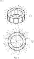
- Fig. 1 shows an ultrasonic motor according to the invention, comprising an ultrasonic actuator 1, which forms a wave resonator 2, wherein the ultrasonic actuator is designed as a hollow cylinder 3 of a piezoelectric material, and on whose a flat end face 5 four friction elements 4 are arranged.
- the ultrasonic actuator 1 is pressed by a force F with its friction elements 4 elastically to the friction surface 6 of a Fritationsticians 7.
- the force F may be caused by the gravity of the ultrasonic actuator, but it may also be caused by an additional element, such as a spring or a magnet.
- FIG. 2 shows the ultrasonic actuator according to Fig. 1 as a single item.
- the ultrasonic actuator has a total of twelve identical peripheral sections or peripheral segments 10.
- Each peripheral section 10 comprises an excitation electrode 11, wherein the exciter electrodes of adjacent circumferential sections 10 do not touch.
- On the inner circumferential surface 14 of the ultrasonic actuator a completely circumferential general electrode 13 is arranged.
- Each excitation electrode 11 forms, with the corresponding opposite portion of the common electrode 13 and the layer of piezoelectric material arranged between the two electrodes, a generator for an acoustic standing wave or deformation wave to be formed in the ultrasonic actuator.
- friction elements 4 are arranged on the flat end face 5, the friction elements each being arranged in the region of the middle between two adjacent exciter electrodes.
- the symmetry line of each friction element runs in the middle between two neighboring exciter electrodes.
- Two adjacent friction elements 4 include a circumferential angle of substantially 90 ° so that there are two pairs of friction elements in which the two corresponding friction elements are arranged diametrically opposite each other.
- Fig. 2 which shows the ultrasonic actuator according to representation 8 in plan view
- the geometric relationships between the individual elements of the ultrasonic actuator are particularly well visible.
- the diametrical planes S divide the hollow cylinder into twelve equal circumferential sections 10.
- the points of intersection of the diametral planes S with the ultrasound actuator 1 are indicated by dotted lines.
- the polarization direction of the piezoceramic layer 15 is indicated by corresponding arrows with the index p.
- the polarization direction here is oriented normal to the electrodes, so that a radially directed polarization results.
- illustration 9 of Fig. 2 the electrical connections A1 to A12 of the excitation electrodes and the electrical connection A0 of the general electrode.
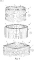
- Fig. 3 shows an alternative embodiment for an ultrasonic actuator of an ultrasonic motor according to the invention.
- excitation electrodes 11 and general electrodes 13 in an alternating arrangement for each generator, wherein layers of piezoceramic material 15 are arranged between the electrode layers (so-called multilayer arrangement).
- the layers are in this case stacked in the axial direction of the ultrasonic actuator, and the polarization direction of the piezoceramic material is normal to the electrodes or normal to the end faces, ie in the axial direction, the polarization directions of each adjacent layers of piezoelectric material are opposite (antiparallel polarization direction).
- All the excitation electrodes 11 of the respective generator are contacted by the respective terminal A1 to A12, while all the common electrodes 13 of the respective generator are contacted via the terminal A0.
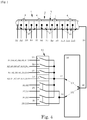
- Fig. 4 shows a block diagram relating to the connection of the ultrasonic actuator of an ultrasonic motor according to the invention with the electrical exciter device 16.
- the corresponding electrical circuit here comprises a switch 20, which comprises the circuit breaker 21 to 26, with the aid of which a connection between the electrical excitation device and the excitation electrodes to be controlled can be realized.
- the breaker 21 is connected to the terminals A1, A4, A5, A8, A9 and A12
- the breaker 22 is connected to the terminals A2, A3, A6, A7, A10 and A11, etc.
- the electrical excitation device 16 provides at its terminals 17 and 18, the electrical AC voltage U1, and at the terminals 19 and 18, the electrical AC voltage U2 ready. These voltages are mutually phase-shifted by the angle 180 °. They have the same frequency fo, whereby in the ultrasonic actuator 1, the sixth mode of the acoustic deformation standing wave (six half waves with ⁇ / 2) is excited or generated. Each of the generators generates a ⁇ / 4 portion of the standing wave.
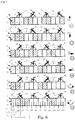
- FIG. 5 Figure 28 shows the FEM model of an ultrasonic actuator of an ultrasonic motor according to the invention in the unexcited state, while Figures 27 and 29 show FEM calculations based on the model shown in Figure 28 of the maximum deformation phases due to the standing wave excited in the ultrasonic actuator.
- This standing wave is generated by the operation of any switch 21 to 26.
- the points 30 of the end face 5 located on the vertices of the standing wave have only one transverse or axial component of the oscillations.
- the points 31 of the end face 5 lying on the sloping portions of the standing wave have both a transverse or axial component and a longitudinal or tangential component of the vibrations.
- any switch 21 to 26 does not change the shape of the generated standing wave. It only changes the position of the shaft with respect to the friction elements 4. The displacement of the shaft is thereby either half a wavelength, i. ⁇ / 2, or one quarter of the wavelength, i. ⁇ / 4.
- Representation 33 corresponds to the position off switch 21 is turned on.
- Representation 34 corresponds to the position off switch 22 turned on.
- Illustration 35 corresponds to the position switch-off switch 23 switched on.
- Representation 36 corresponds to the position off switch 24 is turned on.
- Representation 37 corresponds to the position switch-off 25 is switched on.
- Illustration 38 corresponds to the position off switch 26 is turned on.
- the points 32 move on two different trajectories, namely on the inclined trajectory 40 and the transverse trajectory 41.
- Fig. 7 illustrates the movement of the points 32 of the friction elements 4 on the inclined trajectory 40.
- the inclined trajectory 40 can be decomposed into two components, namely a longitudinal or tangential component 42 and a transverse or axial component 43.
- the longitudinal component 42 causes the trajectory, the friction element 5 moves the actuator 1 in the direction shown by arrow 44 (drive direction).
- the points 32 moving on the transverse movement path 41 do not have a longitudinal movement component, which is why they also have no influence on the movement of the actuator 1.
- a linear movement of the actuator 1 on the friction surface 6 is possible, namely forward (as shown in FIG. 33 of FIG Fig. 6 ) backwards (as shown in 34 of Fig. 6 ), to the right (as shown in Fig. 35 of Fig. 6 ) and to the left (as shown in Fig. 36 of Fig. 6 ). Furthermore, a rotary movement in a clockwise direction (as shown in FIG. 37 of FIG Fig. 6 ) or counterclockwise (as shown in Figure 38 of Fig. 6 ) possible.
- the invention enables a design of the ultrasonic motor, in which the ultrasonic actuator 1 is fixed, which sets the arranged in guides friction table 7 in motion, the guides limit the perpendicular to the end faces 5 of the actuator 1 movement (not shown in the figures ).
Description
Die Erfindung betrifft einen Ultraschallmotor nach den Ansprüchen 1 bis 5.The invention relates to an ultrasonic motor according to
Aus der
Aufgabe der Erfindung ist es, einen Ultraschallmotor bereitzustellen, der mittels nur eines Ultraschallaktors in der Lage ist, eine Zwei- oder Dreikoordinatenbewegung des durch ihn anzutreibenden Elements zu erzeugen.The object of the invention is to provide an ultrasonic motor which is able by means of only one ultrasonic actuator to generate a two- or three-coordinate movement of the element to be driven by it.
Die Lösung der Aufgabe erfolgt durch einen Ultraschallmotor gemäß Anspruch 1, wobei die sich daran anschließenden Unteransprüche mindestens zweckmäßige Ausgestaltungen und Weiterbildungen umfassen.The object is achieved by an ultrasonic motor according to
Demnach wird von einem Ultraschallmotor mit einem piezoelektrischen Ultraschallaktor in Form eines Rings oder Hohlzylinders mit einer inneren Umfangsfläche, einer äußeren Umfangsfläche und zwei die innere und die äußere Umfangsfläche miteinander verbindenden ebenen Stirnflächen, wobei an einer der ebenen Stirnflächen vier Friktionselemente angeordnet sind, ausgegangen. Die Friktionselemente sind über den Umfang des Ultraschallaktors bzw. der Stirnfläche verteilt in jeweils gleichen Abständen zueinander (d.h. äquidistant) angeordnet. Mit anderen Worten liegt zwischen zwei benachbarten Friktionselementen ein Umfangswinkel von 90°, so dass sich jeweils zwei der vier Friktionselemente diametral gegenüber liegen (d.h. mit einem Umfangswinkelabstand von 180°). Die Friktionselemente stehen in Friktions- oder Wirkkontakt mit einer Friktionsfläche eines Elements, beispielsweise eines Friktionstisches, an welche sie elastisch angepresst sind.Thus, an ultrasonic motor having a piezoelectric ultrasonic actuator in the form of a ring or a hollow cylinder having an inner circumferential surface, an outer peripheral surface and two planar end surfaces interconnecting the inner and outer peripheral surfaces, wherein four friction elements are disposed on one of the flat end surfaces. The friction elements are distributed over the circumference of the ultrasound actuator or the end face distributed in equal distances from each other (i.e., equidistant). In other words, there is a circumferential angle of 90 ° between two adjacent friction elements so that each two of the four friction elements are diametrically opposite (i.e., with a circumferential angular separation of 180 °). The friction elements are in frictional or operative contact with a friction surface of an element, such as a Friktionstisches to which they are resiliently pressed.
Außerdem umfasst der erfindungsgemäße Ultraschallmotor eine elektrische Erregervorrichtung. Diese ist vorgesehen zur elektrischen Verbindung mit Erregerelektroden und allgemeinen Elektroden bzw. mit einer allgemeinen Elektrode des Ultraschallaktors, wobei die Erregerelektroden zusammen mit den allgemeinen Elektroden bzw. mit der allgemeinen Elektrode und einer zwischen der Erregerelektrode und der allgemeinen Elektrode angeordneten Schicht piezoelektrischen Materials einen Generator für eine in dem Ultraschallaktor auszubildende akustische Stehwelle bilden. Insgesamt besitzt der Ultraschallaktor zwölf gleiche und über den Umfang des Ultraschallaktors verteilte Generatoren. Jeder Generator ist Teil eines Umfangsabschnitts des Hohlzylinders bzw. Rings, wobei jeder Umfangsabschnitt einen Teilhohlzylinder bildet.In addition, the ultrasonic motor according to the invention comprises an electrical excitation device. This is intended for electrical connection to exciter electrodes and general electrodes or to a general electrode of the ultrasound actuator, wherein the exciter electrodes together with the general electrodes or with the general electrode and a piezoelectric material arranged between the excitation electrode and the general electrode, a generator for form an acoustic standing wave to be formed in the ultrasonic actuator. Overall, the ultrasonic actuator has twelve equal and distributed over the circumference of the ultrasonic actuator generators. Each generator is part of a peripheral portion of the hollow cylinder or ring, wherein each peripheral portion forms a partial hollow cylinder.
Durch entsprechende elektrische Anregung der Generatoren über die elektrische Erregervorrichtung bildet sich in dem Ultraschallaktor, der einen Wellenresonator darstellt, eine akustische Steh- bzw. Deformationswelle aus, und die durch die Stehwelle hervorgerufenen Deformationen des Ultraschallaktors führen zu entsprechenden Auslenkungen der Friktionselemente auf oder entlang einer zur Stirnfläche geneigten Bewegungsbahn und/oder einer zur Stirnfläche im Wesentlichen senkrechten Richtung (Querbewegungsbahn), wobei die geneigte Bewegungsbahn eine Längs- oder Tangentialkomponente und eine Quer- oder Axialkomponenten aufweist, und die Längs- oder Tangentialkomponente im Wesentlichen parallel zur Friktionsfläche verläuft. Hierbei kann durch die Auslenkung der Friktionselemente in der zur Stirnfläche im Wesentlichen senkrechten Richtung (d.h. auf der Querbewegungsbahn) eine Bewegung senkrecht zur Friktionsfläche (z-Richtung) generiert werden, während aufgrund der Auslenkung der Friktionselemente auf oder entlang der zur Stirnfläche geneigten Bewegungsbahn eine Bewegung entlang der Friktionsfläche (x-y-Ebene) generiert werden kann.By appropriate electrical excitation of the generators via the electrical excitation device is formed in the ultrasonic actuator, which is a wave resonator, an acoustic standing or deformation wave, and caused by the standing wave deformations of the ultrasonic actuator lead to corresponding deflections of the friction elements on or along a End face inclined trajectory and / or a direction substantially perpendicular to the end face (transverse movement path), wherein the inclined trajectory having a longitudinal or tangential component and a transverse or axial components, and the longitudinal or tangential component is substantially parallel to the friction surface. In this case, a movement perpendicular to the friction surface (z-direction) can be generated by the deflection of the friction elements in the direction substantially perpendicular to the end face (ie on the transverse movement path), while due to the deflection of the friction elements on or along the inclined path to the end face movement along the friction surface (xy plane) can be generated.
Damit kann der erfindungsgemäße Ultraschallmotor mit nur einem Ultraschallaktor sowohl eine Zweikoordinatenbewegung in einer Ebene (der x-y-Ebene) erzeugen, als auch eine Dreikoordinatenbewegung, bei der zusätzlich eine Bewegung senkrecht zur x-y-Ebene und damit in z-Richtung erfolgt. Hierbei ist einerseits eine Bewegung des Ultraschallaktors relativ zu der Friktionsfläche möglich; andererseits ist auch denkbar, dass der Ultraschallaktor feststeht und eine Relativbewegung des Elements, das die Friktionsfläche bildet, bewirkt.Thus, the ultrasonic motor according to the invention with only one ultrasonic actuator both a two-coordinate movement in a plane (the x-y plane) generate, as well as a three-coordinate movement, in addition, a movement is perpendicular to the x-y plane and thus in the z-direction. In this case, on the one hand, a movement of the ultrasonic actuator relative to the friction surface is possible; On the other hand, it is also conceivable that the ultrasonic actuator is fixed and causes a relative movement of the element which forms the friction surface.
Es kann von Vorteil sein, dass die Erregerelektroden auf der äußeren Umfangsfläche des Ultraschallaktors und die allgemeine Elektrode oder die allgemeinen Elektroden auf der inneren Umfangsfläche des Ultraschallaktors angeordnet sind.It may be advantageous that the excitation electrodes are arranged on the outer peripheral surface of the ultrasonic actuator and the general electrode or the general electrodes on the inner peripheral surface of the ultrasonic actuator.
Ebenso kann es von Vorteil sein, dass die Erregerelektroden, die allgemeinen Elektroden und die jeweils zwischen diesen angeordneten Schichten aus Piezokeramik im Wesentlichen parallel zu den Stirnflächen des Ultraschallaktors angeordnet sind.Likewise, it may be advantageous for the excitation electrodes, the general electrodes and the respective layers of piezoceramics arranged between them to be arranged substantially parallel to the end faces of the ultrasound actuator.
Weiterhin kann es von Vorteil sein, dass die elektrische Erregervorrichtung eine elektrische Wechselspannung mit einer Frequenz bereitstellt, bei der im Ultraschallaktor die sechste Mode der akustischen Stehwelle erzeugt wird.Furthermore, it can be advantageous for the electrical exciter device to provide an alternating electrical voltage with a frequency at which the sixth mode of the acoustic standing wave is generated in the ultrasound actuator.
Hierbei hinaus kann es von Vorteil sein, dass der Ultraschallmotor einen Umschalter für die Elektroden enthält, der diese so mit der elektrischen Erregervorrichtung verbindet, dass bei Erzeugung der sechsten Mode der akustischen Stehwelle in dem Ultraschallaktor bei einem Paar der sich diametral gegenüberliegenden Friktionselemente die maximale Auslenkung auf oder entlang der geneigten Bewegungsbahn auftritt und bei dem anderen Paar der sich diametral gegenüberliegenden Friktionselemente die minimale Auslenkung auf oder entlang der geneigten Bewegungsbahn auftritt.In this case, it may be advantageous that the ultrasonic motor includes a switch for the electrodes, which connects them with the electrical excitation device that when generating the sixth mode of the acoustic standing wave in the ultrasonic actuator at a pair of diametrically opposed friction elements, the maximum deflection on or along the inclined trajectory and in the other pair of diametrically opposed friction elements the minimum deflection on or along the inclined trajectory occurs.
Kurze Beschreibung der Zeichnungen:
-
Fig. 1 : Erfindungsgemäßer Ultraschallmotor (ohne Darstellung der elektrischen Erregervorrichtung) -
Fig. 2 : Darstellung 8: Ultraschallaktor des Ultraschallmotors gemäßFig. 1 in perspektivischer Ansicht; Darstellung 9: Ultraschallaktor des Ultraschallmotors gemäßFig. 1 in Draufsicht (Blickrichtung von oben) -
Fig. 3 : Ausführungsform eines Ultraschallaktors eines erfindungsgemäßen Ultraschallmotors (ohne Darstellung der Friktionselemente) -
Fig. 4 : Blockschaltbild betreffend die Verbindung des Ultrachallaktors eines erfindungsgemäßen Ultraschallmotors mit der elektrischen Erregervorrichtung -
Fig. 5 : Darstellung 28: FEM-Modell eines Ultraschallaktors eines erfindungsgemäßen Ultraschallmotors im unangeregten Zustand;Darstellungen 27 und 29: FEM-Berechnungen der Phasen maximaler Deformation anhand des Modells gemäßDarstellung 28 -
Fig. 6 :Darstellungen 33 bis 38: Einfluss der unterschiedlichen elektrischen Ansteuerung eines Ultraschallaktors eines erfindungsgemäßen Ultrachallmotors auf die Auslenkungsrichtung der Friktionselemente -
Fig. 7 : Kontakt- bzw. Eingriffssituation zwischen einem Friktionselement eines Ultraschallaktors eines erfindungsgemäßen Ultraschallmotors und einer Friktionsfläche
-
Fig. 1 : Ultrasonic motor according to the invention (without representation of the electrical excitation device) -
Fig. 2 Figure 8: Ultrasonic actuator of the ultrasonic motor according toFig. 1 in perspective view; Figure 9: Ultrasonic actuator of the ultrasonic motor according toFig. 1 in plan view (view from above) -
Fig. 3 : Embodiment of an Ultrasonic Actuator of an Ultrasonic Motor According to the Invention (Without Depiction of the Friction Elements) -
Fig. 4 : Block diagram relating to the connection of the ultrrachound actuator of an ultrasonic motor according to the invention with the electrical excitation device -
Fig. 5 FIG. 28: FEM model of an ultrasound actuator of an ultrasound motor according to the invention in the unexcited state; Figures 27 and 29: FEM calculations of the phases of maximum deformation using the model shown in Figure 28 -
Fig. 6 Figures 33 to 38: Influence of the different electrical control of an ultrasonic actuator of an ultrahigh-speed motor according to the invention on the deflection direction of the friction elements -
Fig. 7 : Contact or engagement situation between a friction element of an ultrasonic actuator of an ultrasonic motor according to the invention and a friction surface
Darstellung 8 von
Anhand Darstellung 9 von
Weiterhin ist anhand Darstellung 9 von
Die elektrische Erregervorrichtung 16 stellt an ihren Anschlüssen 17 und 18 die elektrische Wechselspannung U1, und an den Anschlüssen 19 und 18 die elektrische Wechselspannung U2 bereit. Diese Spannungen sind zueinander um den Winkel 180° phasenverschoben. Sie haben die gleiche Frequenz fo, wodurch im Ultraschallaktor 1 die sechste Mode der akustischen Deformations-Stehwelle (sechs Halbwellen mit λ/2) angeregt bzw. erzeugt wird. Jeder der Generatoren erzeugt einen λ/4-Anteil der Stehwelle.The
Das Betätigen eines beliebigen Ausschalters 21 bis 26 führt zu keiner Änderung der Form der erzeugten Stehwelle. Es ändert sich nur die Lage der Welle in Bezug zu den Friktionselementen 4. Die Verschiebung der Welle beträgt dabei entweder ein halbe Wellenlänge, d.h. λ/2, oder aber ein Viertel der Wellenlänge, d.h. λ/4.The operation of any
Die zuvor beschriebene Veränderung der Wellenlage hat eine Änderung der Bewegungsbahn der Punkte 32 der Friktionselemente 4 zur Folge, wie dies in den Darstellungen 33 bis 38 von
Darstellung 33 entspricht hierbei der Stellung Ausschalter 21 eingeschaltet. Darstellung 34 entspricht der Stellung Ausschalter 22 eingeschaltet. Darstellung 35 entspricht der Stellung Ausschalter 23 eingeschaltet. Darstellung 36 entspricht der Stellung Ausschalter 24 eingeschaltet. Darstellung 37 entspricht der Stellung Ausschalter 25 eingeschaltet. Darstellung 38 entspricht der Stellung Ausschalter 26 eingeschaltet.
In allen Fällen bewegen sich die Punkte 32 auf zwei unterschiedlichen Bewegungsbahnen, nämlich auf der geneigten Bewegungsbahn 40 und der Querbewegungsbahn 41.In all cases, the
Die sich auf der Querbewegungsbahn 41 bewegenden Punkte 32 besitzen keine Längsbewegungskomponente, weshalb sie auch keinen Einfluss auf die Bewegung des Aktors 1 haben.The
Das Betätigen der Ausschalter 21 bis 26 führt zu einer Änderung der Bewegungsbahn der Punkte 32, und zwar von einer Querbewegungsbahn 41 zu einer geneigten Bewegungsbahn 40 und zu der in den Darstellungen 33 bis 38 von
Durch das Betätigen der Ausschalter 21 bis 26 ist eine Linearbewegung des Aktors 1 auf der Friktionsfläche 6 möglich, und zwar vorwärts (gemäß Darstellung 33 von
Die Erfindung ermöglicht eine konstruktive Auslegung des Ultraschallmotors, bei dem der Ultraschallaktor 1 befestigt ist, welcher den in Führungen angeordneten Friktionstisch 7 in Bewegung versetzt, wobei die Führungen die zu den Stirnflächen 5 des Aktors 1 senkrecht verlaufenden Bewegung begrenzen (in den Fig. nicht dargestellt).The invention enables a design of the ultrasonic motor, in which the
Claims (5)
- An ultrasonic motor, comprising a piezoelectric ultrasonic actuator (1) having four friction elements (4) disposed thereon, a friction surface (6) which is in frictional contact with the friction elements, and an electrical excitation apparatus (16), wherein the ultrasonic actuator is in the shape of a ring or hollow cylinder, having an inner circumferential surface (14), an outer circumferential surface (12) and two planar end surfaces (5) connecting the inner and the outer circumferential surfaces, wherein the four friction elements are disposed on one of the end surfaces of the ultrasonic actuator so as to be spaced equidistantly with respect to the circumferential direction, such that in each case two of the friction elements lie diametrically opposite, and the ultrasonic actuator comprises twelve identical circumferential sections (10), each of which has a generator for an acoustic standing wave to be formed in the ultrasonic actuator, and each generator has at least one excitation electrode (11), at least one general electrode (13) or a section of a general electrode and a layer of piezo-ceramic material (15) disposed between the excitation electrode and the general electrode or the section of the general electrode,
characterized in that
the generators are operable such that the deformations of the ultrasonic actuator caused by the standing wave lead to deflections of a pair of diametrically opposite friction elements on a movement path inclined with respect to the end surface and to deflections of the other pair of diametrically opposite friction elements on a movement path substantially perpendicular to the end surface, - An ultrasonic motor according to claim 1, characterized in that the excitation electrodes are arranged on the outer circumferential surface of the ultrasonic actuator, and the general electrode or the general electrodes are arranged on the inner circumferential surface of the ultrasonic actuator.
- An ultrasonic motor according to claim 1, characterized in that the excitation electrodes, the general electrodes and the respective layers of piezo-ceramic material arranged therebetween are arranged substantially parallel to the end surfaces of the ultrasonic actuator.
- An ultrasonic motor according to one of the preceding claims, characterized in that the electrical excitation apparatus provides an electrical alternating voltage with a frequency at which the sixth mode of the acoustic standing wave is generated in the ultrasonic actuator.
- An ultrasonic motor according to claim 4, characterized in that it comprises a changeover switch (20) for the electrodes, which connects said electrodes to the electrical excitation apparatus in such a way that upon generating the sixth mode of the acoustic standing wave in the ultrasonic actuator the maximum deflection occurs along the inclined movement part in a pair of the diametrically opposite friction elements, and the minimum deflection occurs along the inclined movement path in the other pair of the diametrically opposite friction elements.
Applications Claiming Priority (2)
| Application Number | Priority Date | Filing Date | Title |
|---|---|---|---|
| DE201310226418 DE102013226418B3 (en) | 2013-12-18 | 2013-12-18 | ultrasonic motor |
| PCT/DE2014/200676 WO2015090312A1 (en) | 2013-12-18 | 2014-12-04 | Ultrasonic motor |
Publications (2)
| Publication Number | Publication Date |
|---|---|
| EP3084852A1 EP3084852A1 (en) | 2016-10-26 |
| EP3084852B1 true EP3084852B1 (en) | 2017-11-22 |
Family
ID=52544235
Family Applications (1)
| Application Number | Title | Priority Date | Filing Date |
|---|---|---|---|
| EP14838779.8A Active EP3084852B1 (en) | 2013-12-18 | 2014-12-04 | Ultrasonic motor |
Country Status (6)
| Country | Link |
|---|---|
| US (1) | US10236797B2 (en) |
| EP (1) | EP3084852B1 (en) |
| JP (1) | JP6326501B2 (en) |
| CN (1) | CN105830329B (en) |
| DE (1) | DE102013226418B3 (en) |
| WO (1) | WO2015090312A1 (en) |
Families Citing this family (10)
| Publication number | Priority date | Publication date | Assignee | Title |
|---|---|---|---|---|
| US10704021B2 (en) | 2012-03-15 | 2020-07-07 | Flodesign Sonics, Inc. | Acoustic perfusion devices |
| CA2935960C (en) | 2014-01-08 | 2023-01-10 | Bart Lipkens | Acoustophoresis device with dual acoustophoretic chamber |
| US11708572B2 (en) | 2015-04-29 | 2023-07-25 | Flodesign Sonics, Inc. | Acoustic cell separation techniques and processes |
| US11377651B2 (en) | 2016-10-19 | 2022-07-05 | Flodesign Sonics, Inc. | Cell therapy processes utilizing acoustophoresis |
| DE102015120282B4 (en) | 2015-11-24 | 2018-01-18 | Physik Instrumente (Pi) Gmbh & Co. Kg | ultrasonic motor |
| US11214789B2 (en) | 2016-05-03 | 2022-01-04 | Flodesign Sonics, Inc. | Concentration and washing of particles with acoustics |
| DE102016112101B4 (en) * | 2016-07-01 | 2018-08-02 | Physik Instrumente (Pi) Gmbh & Co. Kg | Device comprising an ultrasonic actuator and a mounting device, wherein the ultrasonic actuator is arranged on the mounting device |
| FR3068751B1 (en) * | 2017-07-06 | 2019-08-02 | Universite Pierre Et Marie Curie | TRANSMISSION MECHANISM WITH VARIABLE TRANSLATION RATIO |
| EP3725092A4 (en) | 2017-12-14 | 2021-09-22 | FloDesign Sonics, Inc. | Acoustic transducer drive and controller |
| EP3499593A1 (en) * | 2017-12-15 | 2019-06-19 | Physik Instrumente (PI) GmbH & Co. Kg | Electromechanical actuator |
Family Cites Families (16)
| Publication number | Priority date | Publication date | Assignee | Title |
|---|---|---|---|---|
| KR910008930A (en) * | 1989-10-20 | 1991-05-31 | 야마무라 가쯔미 | Ultrasonic motor |
| DE19522072C1 (en) * | 1995-06-17 | 1997-02-06 | Pi Ceramic Gmbh | Piezoelectric motor |
| JP2001298969A (en) * | 2000-04-07 | 2001-10-26 | Mitsuba Corp | Ultrasonic motor |
| DE10154526B4 (en) * | 2001-06-12 | 2007-02-08 | Physik Instrumente (Pi) Gmbh & Co | Piezoelectric actuator |
| DE10314810A1 (en) | 2003-01-08 | 2004-08-05 | Physik Instrumente (Pi) Gmbh & Co. Kg | Method for operating a piezoelectric motor and piezoelectric motor with a stator in the form of a hollow cylindrical oscillator |
| JP4871594B2 (en) * | 2006-01-12 | 2012-02-08 | キヤノン株式会社 | Vibration wave drive device and vibration wave drive device |
| JP2008136318A (en) * | 2006-11-29 | 2008-06-12 | Olympus Corp | Ultrasonic motor and microscope stage |
| DE102008023478A1 (en) * | 2007-11-08 | 2009-05-14 | Physik Instrumente (Pi) Gmbh & Co. Kg | Ultrasonic linear drive with hollow cylindrical oscillator |
| DE102008058484A1 (en) * | 2008-02-28 | 2009-09-10 | Physik Instrumente (Pi) Gmbh & Co. Kg | High precision ultrasonic motor |
| DE102008012992A1 (en) * | 2008-03-07 | 2009-09-10 | Physik Instrumente (Pi) Gmbh & Co. Kg | ultrasonic motor |
| TW201108566A (en) * | 2008-11-21 | 2011-03-01 | Bruce C Sun | Miniature piezoelectric motors for ultra high-precision stepping |
| DE102009049719A1 (en) | 2009-10-17 | 2011-04-21 | Physik Instrumente (Pi) Gmbh & Co. Kg | actuator |
| JP2012039819A (en) * | 2010-08-10 | 2012-02-23 | Olympus Corp | Ultrasonic wave motor |
| JP5744670B2 (en) * | 2011-08-05 | 2015-07-08 | キヤノン株式会社 | Ultrasonic motor and lens apparatus having the same |
| DE102012201863B3 (en) * | 2012-02-08 | 2013-05-02 | Physik Instrumente (Pi) Gmbh & Co. Kg | ultrasonic actuator |
| CN103051243B (en) * | 2013-01-11 | 2015-01-28 | 南京航空航天大学 | Hollow ultrasonic motor with built-in vibrating ring |
-
2013
- 2013-12-18 DE DE201310226418 patent/DE102013226418B3/en active Active
-
2014
- 2014-12-04 JP JP2016541042A patent/JP6326501B2/en active Active
- 2014-12-04 US US15/104,349 patent/US10236797B2/en active Active
- 2014-12-04 WO PCT/DE2014/200676 patent/WO2015090312A1/en active Application Filing
- 2014-12-04 CN CN201480068864.5A patent/CN105830329B/en active Active
- 2014-12-04 EP EP14838779.8A patent/EP3084852B1/en active Active
Also Published As
| Publication number | Publication date |
|---|---|
| US20160336877A1 (en) | 2016-11-17 |
| US10236797B2 (en) | 2019-03-19 |
| WO2015090312A1 (en) | 2015-06-25 |
| EP3084852A1 (en) | 2016-10-26 |
| JP6326501B2 (en) | 2018-05-16 |
| CN105830329B (en) | 2019-03-19 |
| DE102013226418B3 (en) | 2015-04-02 |
| JP2017502637A (en) | 2017-01-19 |
| CN105830329A (en) | 2016-08-03 |
Similar Documents
| Publication | Publication Date | Title |
|---|---|---|
| EP3084852B1 (en) | Ultrasonic motor | |
| EP2882091B1 (en) | Ultrasonic motor and method for operating such a ultrasonic motor | |
| DE102014205577B4 (en) | Ultrasonic motor | |
| EP3172826B1 (en) | Ultrasonic motor | |
| DE19605214A1 (en) | Ultrasonic drive element | |
| DE3500607A1 (en) | Torsional vibration ultrasonic vibrator and a torsional vibration piezo motor | |
| EP2489081B1 (en) | Actuator | |
| DE102013110356B4 (en) | ultrasonic actuator | |
| DE102009051395A1 (en) | actuator | |
| EP2845305A1 (en) | Ultrasonic motor | |
| DE102018104928B3 (en) | ultrasonic motor | |
| DE102013107154A1 (en) | driving device | |
| DE102014209419B3 (en) | ultrasonic actuator | |
| DE102016110124B4 (en) | ultrasonic motor | |
| DE102015120282B4 (en) | ultrasonic motor | |
| EP3844866A1 (en) | Ultrasonic actuator | |
| DE112007001099T5 (en) | vibration actuator | |
| WO2013185758A1 (en) | Single phase ultrasonic motor | |
| DE102013101020B4 (en) | Ultrasonic actuator and ultrasonic motor with such a Ultraschallaktor | |
| DE102013203836B4 (en) | Piezoelectric ultrasonic vibration element and its use | |
| EP3526823B1 (en) | Ultrasonic motor | |
| EP3607592A1 (en) | Method for operating an ultrasonic motor | |
| DE102013221414B4 (en) | Ultrasonic motor | |
| DE102008043667A1 (en) | Multilayer actuator i.e. piezoelectric motor, for window lifting drive of motor vehicle, has electrode planes comprising two electrode sections controlled independent of each other, where sections are arranged on collecting electrodes |
Legal Events
| Date | Code | Title | Description |
|---|---|---|---|
| PUAI | Public reference made under article 153(3) epc to a published international application that has entered the european phase |
Free format text: ORIGINAL CODE: 0009012 |
|
| 17P | Request for examination filed |
Effective date: 20160610 |
|
| AK | Designated contracting states |
Kind code of ref document: A1 Designated state(s): AL AT BE BG CH CY CZ DE DK EE ES FI FR GB GR HR HU IE IS IT LI LT LU LV MC MK MT NL NO PL PT RO RS SE SI SK SM TR |
|
| AX | Request for extension of the european patent |
Extension state: BA ME |
|
| DAX | Request for extension of the european patent (deleted) | ||
| REG | Reference to a national code |
Ref country code: DE Ref legal event code: R079 Ref document number: 502014006363 Country of ref document: DE Free format text: PREVIOUS MAIN CLASS: H01L0041083000 Ipc: H01L0041090000 |
|
| GRAP | Despatch of communication of intention to grant a patent |
Free format text: ORIGINAL CODE: EPIDOSNIGR1 |
|
| RIC1 | Information provided on ipc code assigned before grant |
Ipc: H01L 41/09 20060101AFI20170516BHEP Ipc: H01L 41/083 20060101ALI20170516BHEP Ipc: H02N 2/00 20060101ALI20170516BHEP Ipc: H02N 2/02 20060101ALI20170516BHEP |
|
| INTG | Intention to grant announced |
Effective date: 20170612 |
|
| GRAS | Grant fee paid |
Free format text: ORIGINAL CODE: EPIDOSNIGR3 |
|
| GRAA | (expected) grant |
Free format text: ORIGINAL CODE: 0009210 |
|
| AK | Designated contracting states |
Kind code of ref document: B1 Designated state(s): AL AT BE BG CH CY CZ DE DK EE ES FI FR GB GR HR HU IE IS IT LI LT LU LV MC MK MT NL NO PL PT RO RS SE SI SK SM TR |
|
| REG | Reference to a national code |
Ref country code: GB Ref legal event code: FG4D Free format text: NOT ENGLISH |
|
| REG | Reference to a national code |
Ref country code: CH Ref legal event code: EP |
|
| REG | Reference to a national code |
Ref country code: IE Ref legal event code: FG4D Free format text: LANGUAGE OF EP DOCUMENT: GERMAN |
|
| REG | Reference to a national code |
Ref country code: AT Ref legal event code: REF Ref document number: 949159 Country of ref document: AT Kind code of ref document: T Effective date: 20171215 |
|
| REG | Reference to a national code |
Ref country code: DE Ref legal event code: R096 Ref document number: 502014006363 Country of ref document: DE Ref country code: FR Ref legal event code: PLFP Year of fee payment: 4 |
|
| REG | Reference to a national code |
Ref country code: NL Ref legal event code: FP |
|
| REG | Reference to a national code |
Ref country code: LT Ref legal event code: MG4D |
|
| PG25 | Lapsed in a contracting state [announced via postgrant information from national office to epo] |
Ref country code: LT Free format text: LAPSE BECAUSE OF FAILURE TO SUBMIT A TRANSLATION OF THE DESCRIPTION OR TO PAY THE FEE WITHIN THE PRESCRIBED TIME-LIMIT Effective date: 20171122 Ref country code: ES Free format text: LAPSE BECAUSE OF FAILURE TO SUBMIT A TRANSLATION OF THE DESCRIPTION OR TO PAY THE FEE WITHIN THE PRESCRIBED TIME-LIMIT Effective date: 20171122 Ref country code: SE Free format text: LAPSE BECAUSE OF FAILURE TO SUBMIT A TRANSLATION OF THE DESCRIPTION OR TO PAY THE FEE WITHIN THE PRESCRIBED TIME-LIMIT Effective date: 20171122 Ref country code: NO Free format text: LAPSE BECAUSE OF FAILURE TO SUBMIT A TRANSLATION OF THE DESCRIPTION OR TO PAY THE FEE WITHIN THE PRESCRIBED TIME-LIMIT Effective date: 20180222 Ref country code: FI Free format text: LAPSE BECAUSE OF FAILURE TO SUBMIT A TRANSLATION OF THE DESCRIPTION OR TO PAY THE FEE WITHIN THE PRESCRIBED TIME-LIMIT Effective date: 20171122 |
|
| PG25 | Lapsed in a contracting state [announced via postgrant information from national office to epo] |
Ref country code: RS Free format text: LAPSE BECAUSE OF FAILURE TO SUBMIT A TRANSLATION OF THE DESCRIPTION OR TO PAY THE FEE WITHIN THE PRESCRIBED TIME-LIMIT Effective date: 20171122 Ref country code: BG Free format text: LAPSE BECAUSE OF FAILURE TO SUBMIT A TRANSLATION OF THE DESCRIPTION OR TO PAY THE FEE WITHIN THE PRESCRIBED TIME-LIMIT Effective date: 20180222 Ref country code: LV Free format text: LAPSE BECAUSE OF FAILURE TO SUBMIT A TRANSLATION OF THE DESCRIPTION OR TO PAY THE FEE WITHIN THE PRESCRIBED TIME-LIMIT Effective date: 20171122 Ref country code: HR Free format text: LAPSE BECAUSE OF FAILURE TO SUBMIT A TRANSLATION OF THE DESCRIPTION OR TO PAY THE FEE WITHIN THE PRESCRIBED TIME-LIMIT Effective date: 20171122 Ref country code: GR Free format text: LAPSE BECAUSE OF FAILURE TO SUBMIT A TRANSLATION OF THE DESCRIPTION OR TO PAY THE FEE WITHIN THE PRESCRIBED TIME-LIMIT Effective date: 20180223 |
|
| REG | Reference to a national code |
Ref country code: DE Ref legal event code: R119 Ref document number: 502014006363 Country of ref document: DE |
|
| PG25 | Lapsed in a contracting state [announced via postgrant information from national office to epo] |
Ref country code: SK Free format text: LAPSE BECAUSE OF FAILURE TO SUBMIT A TRANSLATION OF THE DESCRIPTION OR TO PAY THE FEE WITHIN THE PRESCRIBED TIME-LIMIT Effective date: 20171122 Ref country code: EE Free format text: LAPSE BECAUSE OF FAILURE TO SUBMIT A TRANSLATION OF THE DESCRIPTION OR TO PAY THE FEE WITHIN THE PRESCRIBED TIME-LIMIT Effective date: 20171122 Ref country code: CY Free format text: LAPSE BECAUSE OF FAILURE TO SUBMIT A TRANSLATION OF THE DESCRIPTION OR TO PAY THE FEE WITHIN THE PRESCRIBED TIME-LIMIT Effective date: 20171122 Ref country code: DK Free format text: LAPSE BECAUSE OF FAILURE TO SUBMIT A TRANSLATION OF THE DESCRIPTION OR TO PAY THE FEE WITHIN THE PRESCRIBED TIME-LIMIT Effective date: 20171122 Ref country code: CZ Free format text: LAPSE BECAUSE OF FAILURE TO SUBMIT A TRANSLATION OF THE DESCRIPTION OR TO PAY THE FEE WITHIN THE PRESCRIBED TIME-LIMIT Effective date: 20171122 |
|
| REG | Reference to a national code |
Ref country code: CH Ref legal event code: PL |
|
| PG25 | Lapsed in a contracting state [announced via postgrant information from national office to epo] |
Ref country code: IT Free format text: LAPSE BECAUSE OF FAILURE TO SUBMIT A TRANSLATION OF THE DESCRIPTION OR TO PAY THE FEE WITHIN THE PRESCRIBED TIME-LIMIT Effective date: 20171122 Ref country code: SM Free format text: LAPSE BECAUSE OF FAILURE TO SUBMIT A TRANSLATION OF THE DESCRIPTION OR TO PAY THE FEE WITHIN THE PRESCRIBED TIME-LIMIT Effective date: 20171122 Ref country code: PL Free format text: LAPSE BECAUSE OF FAILURE TO SUBMIT A TRANSLATION OF THE DESCRIPTION OR TO PAY THE FEE WITHIN THE PRESCRIBED TIME-LIMIT Effective date: 20171122 |
|
| REG | Reference to a national code |
Ref country code: IE Ref legal event code: MM4A |
|
| PG25 | Lapsed in a contracting state [announced via postgrant information from national office to epo] |
Ref country code: LU Free format text: LAPSE BECAUSE OF NON-PAYMENT OF DUE FEES Effective date: 20171204 Ref country code: MT Free format text: LAPSE BECAUSE OF FAILURE TO SUBMIT A TRANSLATION OF THE DESCRIPTION OR TO PAY THE FEE WITHIN THE PRESCRIBED TIME-LIMIT Effective date: 20171122 |
|
| PLBE | No opposition filed within time limit |
Free format text: ORIGINAL CODE: 0009261 |
|
| STAA | Information on the status of an ep patent application or granted ep patent |
Free format text: STATUS: NO OPPOSITION FILED WITHIN TIME LIMIT |
|
| 26N | No opposition filed |
Effective date: 20180823 |
|
| PG25 | Lapsed in a contracting state [announced via postgrant information from national office to epo] |
Ref country code: IE Free format text: LAPSE BECAUSE OF NON-PAYMENT OF DUE FEES Effective date: 20171204 Ref country code: DE Free format text: LAPSE BECAUSE OF NON-PAYMENT OF DUE FEES Effective date: 20180703 |
|
| PG25 | Lapsed in a contracting state [announced via postgrant information from national office to epo] |
Ref country code: LI Free format text: LAPSE BECAUSE OF NON-PAYMENT OF DUE FEES Effective date: 20171231 Ref country code: CH Free format text: LAPSE BECAUSE OF NON-PAYMENT OF DUE FEES Effective date: 20171231 Ref country code: SI Free format text: LAPSE BECAUSE OF FAILURE TO SUBMIT A TRANSLATION OF THE DESCRIPTION OR TO PAY THE FEE WITHIN THE PRESCRIBED TIME-LIMIT Effective date: 20171122 |
|
| PG25 | Lapsed in a contracting state [announced via postgrant information from national office to epo] |
Ref country code: HU Free format text: LAPSE BECAUSE OF FAILURE TO SUBMIT A TRANSLATION OF THE DESCRIPTION OR TO PAY THE FEE WITHIN THE PRESCRIBED TIME-LIMIT; INVALID AB INITIO Effective date: 20141204 Ref country code: MC Free format text: LAPSE BECAUSE OF FAILURE TO SUBMIT A TRANSLATION OF THE DESCRIPTION OR TO PAY THE FEE WITHIN THE PRESCRIBED TIME-LIMIT Effective date: 20171122 |
|
| GBPC | Gb: european patent ceased through non-payment of renewal fee |
Effective date: 20181204 |
|
| PG25 | Lapsed in a contracting state [announced via postgrant information from national office to epo] |
Ref country code: RO Free format text: LAPSE BECAUSE OF FAILURE TO SUBMIT A TRANSLATION OF THE DESCRIPTION OR TO PAY THE FEE WITHIN THE PRESCRIBED TIME-LIMIT Effective date: 20171122 |
|
| PG25 | Lapsed in a contracting state [announced via postgrant information from national office to epo] |
Ref country code: MK Free format text: LAPSE BECAUSE OF FAILURE TO SUBMIT A TRANSLATION OF THE DESCRIPTION OR TO PAY THE FEE WITHIN THE PRESCRIBED TIME-LIMIT Effective date: 20171122 |
|
| PG25 | Lapsed in a contracting state [announced via postgrant information from national office to epo] |
Ref country code: GB Free format text: LAPSE BECAUSE OF NON-PAYMENT OF DUE FEES Effective date: 20181204 |
|
| PG25 | Lapsed in a contracting state [announced via postgrant information from national office to epo] |
Ref country code: TR Free format text: LAPSE BECAUSE OF FAILURE TO SUBMIT A TRANSLATION OF THE DESCRIPTION OR TO PAY THE FEE WITHIN THE PRESCRIBED TIME-LIMIT Effective date: 20171122 |
|
| PG25 | Lapsed in a contracting state [announced via postgrant information from national office to epo] |
Ref country code: PT Free format text: LAPSE BECAUSE OF FAILURE TO SUBMIT A TRANSLATION OF THE DESCRIPTION OR TO PAY THE FEE WITHIN THE PRESCRIBED TIME-LIMIT Effective date: 20171122 |
|
| PG25 | Lapsed in a contracting state [announced via postgrant information from national office to epo] |
Ref country code: AL Free format text: LAPSE BECAUSE OF FAILURE TO SUBMIT A TRANSLATION OF THE DESCRIPTION OR TO PAY THE FEE WITHIN THE PRESCRIBED TIME-LIMIT Effective date: 20171122 Ref country code: IS Free format text: LAPSE BECAUSE OF FAILURE TO SUBMIT A TRANSLATION OF THE DESCRIPTION OR TO PAY THE FEE WITHIN THE PRESCRIBED TIME-LIMIT Effective date: 20180322 |
|
| REG | Reference to a national code |
Ref country code: AT Ref legal event code: MM01 Ref document number: 949159 Country of ref document: AT Kind code of ref document: T Effective date: 20191204 |
|
| PG25 | Lapsed in a contracting state [announced via postgrant information from national office to epo] |
Ref country code: AT Free format text: LAPSE BECAUSE OF NON-PAYMENT OF DUE FEES Effective date: 20191204 |
|
| PGFP | Annual fee paid to national office [announced via postgrant information from national office to epo] |
Ref country code: BE Payment date: 20221220 Year of fee payment: 9 |
|
| P01 | Opt-out of the competence of the unified patent court (upc) registered |
Effective date: 20230602 |
|
| PGFP | Annual fee paid to national office [announced via postgrant information from national office to epo] |
Ref country code: NL Payment date: 20231219 Year of fee payment: 10 Ref country code: FR Payment date: 20231220 Year of fee payment: 10 |
|
| PGFP | Annual fee paid to national office [announced via postgrant information from national office to epo] |
Ref country code: BE Payment date: 20231218 Year of fee payment: 10 |