EP3083447B1 - Interchangeable capsule to prepare an infusion of a powdered product, and relative method to obtain this infusion - Google Patents
Interchangeable capsule to prepare an infusion of a powdered product, and relative method to obtain this infusion Download PDFInfo
- Publication number
- EP3083447B1 EP3083447B1 EP14830720.0A EP14830720A EP3083447B1 EP 3083447 B1 EP3083447 B1 EP 3083447B1 EP 14830720 A EP14830720 A EP 14830720A EP 3083447 B1 EP3083447 B1 EP 3083447B1
- Authority
- EP
- European Patent Office
- Prior art keywords
- basket
- cup
- shaped body
- support elements
- infusion
- Prior art date
- Legal status (The legal status is an assumption and is not a legal conclusion. Google has not performed a legal analysis and makes no representation as to the accuracy of the status listed.)
- Not-in-force
Links
Images
Classifications
-
- B—PERFORMING OPERATIONS; TRANSPORTING
- B65—CONVEYING; PACKING; STORING; HANDLING THIN OR FILAMENTARY MATERIAL
- B65D—CONTAINERS FOR STORAGE OR TRANSPORT OF ARTICLES OR MATERIALS, e.g. BAGS, BARRELS, BOTTLES, BOXES, CANS, CARTONS, CRATES, DRUMS, JARS, TANKS, HOPPERS, FORWARDING CONTAINERS; ACCESSORIES, CLOSURES, OR FITTINGS THEREFOR; PACKAGING ELEMENTS; PACKAGES
- B65D65/00—Wrappers or flexible covers; Packaging materials of special type or form
- B65D65/38—Packaging materials of special type or form
- B65D65/46—Applications of disintegrable, dissolvable or edible materials
- B65D65/466—Bio- or photodegradable packaging materials
-
- A—HUMAN NECESSITIES
- A47—FURNITURE; DOMESTIC ARTICLES OR APPLIANCES; COFFEE MILLS; SPICE MILLS; SUCTION CLEANERS IN GENERAL
- A47J—KITCHEN EQUIPMENT; COFFEE MILLS; SPICE MILLS; APPARATUS FOR MAKING BEVERAGES
- A47J31/00—Apparatus for making beverages
- A47J31/40—Beverage-making apparatus with dispensing means for adding a measured quantity of ingredients, e.g. coffee, water, sugar, cocoa, milk, tea
- A47J31/407—Beverage-making apparatus with dispensing means for adding a measured quantity of ingredients, e.g. coffee, water, sugar, cocoa, milk, tea with ingredient-containing cartridges; Cartridge-perforating means
-
- A—HUMAN NECESSITIES
- A47—FURNITURE; DOMESTIC ARTICLES OR APPLIANCES; COFFEE MILLS; SPICE MILLS; SUCTION CLEANERS IN GENERAL
- A47J—KITCHEN EQUIPMENT; COFFEE MILLS; SPICE MILLS; APPARATUS FOR MAKING BEVERAGES
- A47J31/00—Apparatus for making beverages
- A47J31/44—Parts or details or accessories of beverage-making apparatus
-
- B—PERFORMING OPERATIONS; TRANSPORTING
- B65—CONVEYING; PACKING; STORING; HANDLING THIN OR FILAMENTARY MATERIAL
- B65D—CONTAINERS FOR STORAGE OR TRANSPORT OF ARTICLES OR MATERIALS, e.g. BAGS, BARRELS, BOTTLES, BOXES, CANS, CARTONS, CRATES, DRUMS, JARS, TANKS, HOPPERS, FORWARDING CONTAINERS; ACCESSORIES, CLOSURES, OR FITTINGS THEREFOR; PACKAGING ELEMENTS; PACKAGES
- B65D43/00—Lids or covers for rigid or semi-rigid containers
- B65D43/02—Removable lids or covers
-
- B—PERFORMING OPERATIONS; TRANSPORTING
- B65—CONVEYING; PACKING; STORING; HANDLING THIN OR FILAMENTARY MATERIAL
- B65D—CONTAINERS FOR STORAGE OR TRANSPORT OF ARTICLES OR MATERIALS, e.g. BAGS, BARRELS, BOTTLES, BOXES, CANS, CARTONS, CRATES, DRUMS, JARS, TANKS, HOPPERS, FORWARDING CONTAINERS; ACCESSORIES, CLOSURES, OR FITTINGS THEREFOR; PACKAGING ELEMENTS; PACKAGES
- B65D85/00—Containers, packaging elements or packages, specially adapted for particular articles or materials
- B65D85/70—Containers, packaging elements or packages, specially adapted for particular articles or materials for materials not otherwise provided for
- B65D85/804—Disposable containers or packages with contents which are mixed, infused or dissolved in situ, i.e. without having been previously removed from the package
- B65D85/8043—Packages adapted to allow liquid to pass through the contents
- B65D85/8049—Details of the inlet
-
- B—PERFORMING OPERATIONS; TRANSPORTING
- B65—CONVEYING; PACKING; STORING; HANDLING THIN OR FILAMENTARY MATERIAL
- B65D—CONTAINERS FOR STORAGE OR TRANSPORT OF ARTICLES OR MATERIALS, e.g. BAGS, BARRELS, BOTTLES, BOXES, CANS, CARTONS, CRATES, DRUMS, JARS, TANKS, HOPPERS, FORWARDING CONTAINERS; ACCESSORIES, CLOSURES, OR FITTINGS THEREFOR; PACKAGING ELEMENTS; PACKAGES
- B65D85/00—Containers, packaging elements or packages, specially adapted for particular articles or materials
- B65D85/70—Containers, packaging elements or packages, specially adapted for particular articles or materials for materials not otherwise provided for
- B65D85/804—Disposable containers or packages with contents which are mixed, infused or dissolved in situ, i.e. without having been previously removed from the package
- B65D85/8043—Packages adapted to allow liquid to pass through the contents
- B65D85/8055—Means for influencing the liquid flow inside the package
-
- B—PERFORMING OPERATIONS; TRANSPORTING
- B65—CONVEYING; PACKING; STORING; HANDLING THIN OR FILAMENTARY MATERIAL
- B65D—CONTAINERS FOR STORAGE OR TRANSPORT OF ARTICLES OR MATERIALS, e.g. BAGS, BARRELS, BOTTLES, BOXES, CANS, CARTONS, CRATES, DRUMS, JARS, TANKS, HOPPERS, FORWARDING CONTAINERS; ACCESSORIES, CLOSURES, OR FITTINGS THEREFOR; PACKAGING ELEMENTS; PACKAGES
- B65D85/00—Containers, packaging elements or packages, specially adapted for particular articles or materials
- B65D85/70—Containers, packaging elements or packages, specially adapted for particular articles or materials for materials not otherwise provided for
- B65D85/804—Disposable containers or packages with contents which are mixed, infused or dissolved in situ, i.e. without having been previously removed from the package
- B65D85/8043—Packages adapted to allow liquid to pass through the contents
- B65D85/8061—Filters
-
- B—PERFORMING OPERATIONS; TRANSPORTING
- B65—CONVEYING; PACKING; STORING; HANDLING THIN OR FILAMENTARY MATERIAL
- B65D—CONTAINERS FOR STORAGE OR TRANSPORT OF ARTICLES OR MATERIALS, e.g. BAGS, BARRELS, BOTTLES, BOXES, CANS, CARTONS, CRATES, DRUMS, JARS, TANKS, HOPPERS, FORWARDING CONTAINERS; ACCESSORIES, CLOSURES, OR FITTINGS THEREFOR; PACKAGING ELEMENTS; PACKAGES
- B65D85/00—Containers, packaging elements or packages, specially adapted for particular articles or materials
- B65D85/70—Containers, packaging elements or packages, specially adapted for particular articles or materials for materials not otherwise provided for
- B65D85/804—Disposable containers or packages with contents which are mixed, infused or dissolved in situ, i.e. without having been previously removed from the package
- B65D85/8043—Packages adapted to allow liquid to pass through the contents
- B65D85/8064—Sealing means for the interface with the processing machine
Definitions
- the present invention relates to an interchangeable capsule to prepare an infusion of a powdered product, for example coffee or similar products.
- the present invention also relates to a method for obtaining an infusion of said powdered product.
- the present invention is directed to prepare the so-called "American coffee”.
- the present invention has advantageous but not exclusive application to the interchangeable capsules to prepare an infusion of "American coffee” (to which the following description will make explicit reference without loss of generality), the teachings of the present invention may be applied to any type of interchangeable capsule for example to the interchangeable capsules for espresso coffee, tea, chamomile etc..
- American coffee is an infusion obtained by the use of a particular machine wherein the hot water passes through a filter containing the grounded, un-pressed coffee and is deposited by gravity into an underlying carafe.
- the coffee that is used to prepare said beverage differs from that used in "moka” machines or Italian espresso by the fact of being coarsely ground and not being subjected to any precompression when arranged inside the capsule.
- Coffee maker machines specially made to prepare American coffee and characterized by a very simple operation are commercially available.
- these machines comprise a water tank, a pump that sends the heated water inside a small container provided with a paper filter containing the coffee.
- the hot water submerges the coffee and, passing through the paper filter, falls by gravity into the underlying carafe suited to keep the drink hot for a long time as it is heated by a suitable electrical resistance element.
- capsules which have an outer casing wherein a paper filter partly filled with un-pressed coffee is inserted have recently appeared on the market.
- the lid and the bottom in plastic material are perforated so as to create a flow of hot water allowing an infusion of the coffee powder.
- the capsules currently on the market do not work reliably. In fact normally only providing a filter on the bottom, the incoming hot water is induced to flow along substantially vertical preferential fluid threads and therefore does not affect the entire mass of the powdered product contained inside the capsule.
- the main purpose of the present invention is to provide an interchangeable infusion capsule wherein the infusion water path within the capsule itself is as extended and tortuous as possible to delay the infusion time and to affect a greater quantity of product as possible.
- Further object of the present invention is to provide an innovative method for obtaining said infusion.
- the interchangeable capsule 90 is suited to contain inside, as will be better explained later, a certain quantity of a powdered product (for example coffee) for obtaining an infusion, in particular of "American coffee” according to the definition given above.
- a powdered product for example coffee
- the interchangeable capsule 90 comprises a cup-shaped body 101, which has a longitudinal axis (Y), an inner cavity 91, an upper opening 92 and a lower opening 93 opposite to each other.
- the capsule 90 also comprises a lid 102, which closes said upper opening 92, and a basket 94, which is arranged inside the cup-shaped body 101 and is suited to house the powdered product.
- the basket 94 is made substantially of water-permeable material and acts as a filtering means for the infusion created by the water and by the powdered product, as will be further and better explained.
- the basket 94 is made of non-woven fabric; alternatively, the basket 94 is made of plastic material for food use and has a plurality of micro slits for filtering the infusion.
- the basket 94 is made of a deformable material.
- the basket 94 is fixed inside the capsule 90 by means of the interaction between the cup-shaped body 101 and the lid 102 and rests on the bottom 101A of the cup-shaped body 101, as will be better explained later.
- the capsule 90 comprises, finally, a base 100 defined by a disc of rigid material with a circular profile.
- the bottom cover 100 is made of plastic material suitable for food use.
- the bottom cover 100 is inserted in the basket 92 so as to extend transversely to the longitudinal axis (Y) and is interposed between the upper opening 92 and the lower opening 93.
- the cup-shaped body 101 comprises, in turn, a bottom 101A obtained advantageously, but not necessarily, in one piece with a lateral wall 101B.
- an axis (X) passes, that lies substantially on a plane (n) which defines a substantially horizontal direction.
- any "substantially horizontal” body element or device is a body element or device that lies substantially on the plane (n). It must obviously be considered as “substantially horizontal” also body elements or devices which lie substantially on any plane parallel to the plane (n).
- the longitudinal axis (Y) is a central vertical axis of symmetry perpendicular to said axis (X).
- any body element or device “substantially vertical” is a body element or device that substantially extends according to the direction defined by the axis (Y).
- the lateral wall 101B has the usual substantially frusto-conical countersunk shape along the axis (Y).
- the cup-shaped body 101 has an upper end 103 and comprises a contact edge 104 in the shape of a circular crown which protrudes radially outside the lateral wall 101B to ensure that the entire interchangeable capsule 90 can be housed in an appropriate receptacle obtained in a percolator machine (not shown).
- the supporting edge 104 also has a circular recess 104A obtained along the entire inner circular perimeter of the contact edge 104 itself. The recess 104A is facing inside the cavity 91.
- the cup-shaped body 101 comprises, furthermore, a ring 111 coaxial with the axis (Y) and which axially protrudes from the bottom 101A outside of the cup-shaped body 101 itself.
- the ring 111 is suited to form a watertight sealing area in contact with a contact base of the capsule 90.
- the bottom 101A, the lateral wall 101B, the contact edge 104 and the ring 111 are made in one piece with a suitable, known type plastic material for food use.
- the cup-shaped body 101 also comprises a plurality of ribs 105 that protrude longitudinally to the lateral wall 101B and within the cavity 91.
- the ribs 105 are evenly distributed around the axis (Y).
- Two adjacent ribs 105 of the cup-shaped body 101 define a respective infusion channel 106.
- Each rib 105 extends from the bottom 101A up to about 80% of the overall longitudinal extension of the cavity 91.
- the cup-shaped body 101 comprises, furthermore, a plurality of support elements 107, which protrude from the bottom 101A inside the cavity 91.
- the lower opening 93 is concentric with the axis (Y) and the support elements 107 are evenly distributed around said lower opening 93.
- the support elements 107 form a labyrinth path.
- the support elements 107 are divided into radial walls 107A and curved walls 107B.
- the radial walls 107A are interposed between the curved walls 107B and the opening 93.
- the curved walls 107B are evenly distributed around the longitudinal axis (Y) and are formed as portions of a cylindrical body.
- the walls 107B are four and each curved wall 107B has a central angle of about 80°.
- the radial walls 107A are evenly distributed around the longitudinal axis (Y).
- the radial walls 107A are fourteen.
- each support element 107 is spaced from another support element 107, so that on the bottom of the cup-shaped body 101 a labyrinth path arranged radially around the lower opening 93 is formed.
- the basket 94 has the shape of a cup-shaped body and comprises a lateral wall 95 and a bottom 96, which delimit an inner cavity 97 and an upper opening 98.
- the basket 94 also comprises an edge 99 which projects radially outwards from the lateral wall 95.
- the lid 102 has a substantially circular shape in plan and has a circular shaped central hole 108 for the passage of water.
- the lid 102 is made of known type plastic material for food products.
- the lid 102 also comprises a filter 109 suited to close the hole 108.
- the filter 109 is made of non-woven fabric or, alternatively, is made of plastic material for food use and is suited to be torn at the time of use.
- the lid is made of a peelable film material fixed in a known manner, for example welded, on the edge 104 of the cup-shaped body 101.
- the lid is continuous and has no holes or filters.
- the basket 94 is arranged within the cup-shaped body 101 so that its bottom 96 is in contact with the support elements 107 of the cup-shaped body 101 itself.
- the bottom 96 of the basket 94 is fixed in a known manner, for example welded, on the support elements 107.
- the edge 99 of the basket 94 is supported on the recess 104A of the cup-shaped body 101.
- the edge 99 is welded in a known way on the recess 104A.
- the bottom cover 100 is inserted inside the cavity 97 of the basket 94 and is arranged so as to be coaxial with the axis (Y). Preferably, the bottom cover 100 is resting on the bottom 96 of the basket 94.
- the bottom cover 100 is fixed to the bottom 96 of the basket 94 by way of known methods (hence the bottom cover 100 is fixed by means of the basket 94 also to the support elements 107); for example, the bottom cover 100 is welded or glued to the bottom of the basket 94.
- the bottom cover 100 is fixed to the bottom 96 of the basket 94 and to the outside of the cavity 97.
- the basket 94 has a tubular shape and the bottom cover 100 is arranged to close said tubular shape acting substantially as a bottom for the basket 94.
- the bottom cover 100 is fixed, for example welded or glued, onto the support elements 107.
- the lid 102 is arranged within the upper opening 92 and is coaxial with the longitudinal axis (Y).
- the lid 102 is supported within the recess 104A and on the edge 99.
- the lid 102 is welded to the edge 104 of the cup shaped body 101 at the recess 104A.
- the lid 102 is mounted with interference inside the edge 104 of the cup-shaped body 101 so as to hold the edge 99 of the basket 94 against the cup-shaped body 101 itself.
- the cup-shaped body 101' comprises a plurality of support elements 107', which protrude from the bottom 96 inside the cup-shaped body 101 itself.
- the support elements 107' are arranged radially around the axis (Y).
- the support elements 107' form a labyrinth path.
- the support elements 107' are divided into bars of larger dimensions 107'A and into bars of smaller dimensions 107'B. Two adjacent bars of smaller dimensions 107'B are interspersed with a bar of larger dimensions 107'A.
- the different arrangements of the support elements 107 or 107' on the bottom 96 of the cup-shaped body 101 or 101' are suited to maximize the outflow and the quality of the infusion.
- the cup-shaped body 101, 101' and/or the basket 94 and/or the lid 102 are made of biodegradable material.
- the operation of the present capsule 90 is the following:
- each protrusion 110 is made so as to be arranged at least partially around a respective rib 105.
- each protrusion 110 is tapered in the vicinity of both ends.
- each protrusion 110 has a substantially trapezoidal cross-section the size of which varies along the axis (Y).
- each protrusion has a radial extension along the lateral wall 95 in correspondence of the lower longitudinal ends and increased in correspondence to a central area.
- the trapezoidal profiles of two adjacent protrusions 110 are in contact with each other in the vicinity of a substantially central area.
- Each protrusion 110 is suited to wrap, at least partially, a respective rib 105, as will be better explained in the following.
- the cup-shaped body 101, 101' can be tightened below the edge 104 so as to cause a plastic deformation in the cup-shaped body 101, 101' itself, and to allow to extract the lid 102.
- the bottom cover 100 is transverse to the direction F1 of the liquid inserted in the basket 94 so as to divert the direction horizontally.
- the basket 94 basically acts as a filtering means wherein the lateral wall 95 is suited to filter the infusion created by the mixing of water and powdered product.
- the present invention also relates to a method for the production of a beverage infusion in particular of American coffee; the method is characterized by the following steps:
Description
- The present invention relates to an interchangeable capsule to prepare an infusion of a powdered product, for example coffee or similar products.
- The present invention also relates to a method for obtaining an infusion of said powdered product.
- In particular, the present invention is directed to prepare the so-called "American coffee".
- Incidentally, although the present invention has advantageous but not exclusive application to the interchangeable capsules to prepare an infusion of "American coffee" (to which the following description will make explicit reference without loss of generality), the teachings of the present invention may be applied to any type of interchangeable capsule for example to the interchangeable capsules for espresso coffee, tea, chamomile etc..
- As known, being defined as "American coffee" is an infusion obtained by the use of a particular machine wherein the hot water passes through a filter containing the grounded, un-pressed coffee and is deposited by gravity into an underlying carafe.
- The coffee that is used to prepare said beverage differs from that used in "moka" machines or Italian espresso by the fact of being coarsely ground and not being subjected to any precompression when arranged inside the capsule.
- Coffee maker machines specially made to prepare American coffee and characterized by a very simple operation are commercially available.
- In fact, these machines comprise a water tank, a pump that sends the heated water inside a small container provided with a paper filter containing the coffee. The hot water submerges the coffee and, passing through the paper filter, falls by gravity into the underlying carafe suited to keep the drink hot for a long time as it is heated by a suitable electrical resistance element.
- In addition to the traditional American coffee makers wherein the cup-shaped filter is filled manually by the user, capsules which have an outer casing wherein a paper filter partly filled with un-pressed coffee is inserted have recently appeared on the market.
- By means of specialized percolator machines the lid and the bottom in plastic material are perforated so as to create a flow of hot water allowing an infusion of the coffee powder.
- However, the capsules currently on the market do not work reliably. In fact normally only providing a filter on the bottom, the incoming hot water is induced to flow along substantially vertical preferential fluid threads and therefore does not affect the entire mass of the powdered product contained inside the capsule.
- It is also known, by
US 2013/156897 A1 orUS 2006/065127 A1 orUS 2011/274802 A1 , to provide a capsule comprising a bottom deflector or lateral ribs so as to affect the circulation of the infusion and improve the quality of the "American coffee". However these known capsules have the disadvantage that the quality of the infusion is still not maximized. - Therefore, the main purpose of the present invention is to provide an interchangeable infusion capsule wherein the infusion water path within the capsule itself is as extended and tortuous as possible to delay the infusion time and to affect a greater quantity of product as possible.
- Further object of the present invention is to provide an innovative method for obtaining said infusion.
- According to the present invention, therefore, a interchangeable capsule is obtained, as claimed in claim 1 or in any of the claims depending directly or indirectly on claim 1.
- Always in accordance to the principles of the present invention, is provided an innovative method for obtaining an infusion of a powdered product, as claimed in claim 13 or in any of the claims depending directly or indirectly on claim 13.
- For a better understanding of the invention in the following is described a purely illustrative and not limitative embodiment, with the aid of the accompanying drawings, wherein:
-
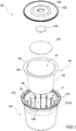
Figure 1 illustrates an exploded view of a capsule according to the present invention; -
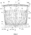
Figure 2 is a longitudinal section of the capsule, in use, according to the present invention; -
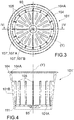
Figure 3 is a plan view of a variant in a first detail; and, -
Figure 4 illustrates the section IV-IV ofFigure 3 . - In the attached figures a preferred embodiment of an
interchangeable capsule 90 according to the teachings of the present invention has been shown. - The
interchangeable capsule 90 is suited to contain inside, as will be better explained later, a certain quantity of a powdered product (for example coffee) for obtaining an infusion, in particular of "American coffee" according to the definition given above. - The
interchangeable capsule 90 comprises a cup-shaped body 101, which has a longitudinal axis (Y), aninner cavity 91, anupper opening 92 and alower opening 93 opposite to each other. Thecapsule 90 also comprises alid 102, which closes saidupper opening 92, and abasket 94, which is arranged inside the cup-shaped body 101 and is suited to house the powdered product. - The
basket 94 is made substantially of water-permeable material and acts as a filtering means for the infusion created by the water and by the powdered product, as will be further and better explained. Preferably, thebasket 94 is made of non-woven fabric; alternatively, thebasket 94 is made of plastic material for food use and has a plurality of micro slits for filtering the infusion. Preferably, thebasket 94 is made of a deformable material. - The
basket 94 is fixed inside thecapsule 90 by means of the interaction between the cup-shaped body 101 and thelid 102 and rests on thebottom 101A of the cup-shaped body 101, as will be better explained later. Thecapsule 90 comprises, finally, abase 100 defined by a disc of rigid material with a circular profile. Preferably, thebottom cover 100 is made of plastic material suitable for food use. Thebottom cover 100 is inserted in thebasket 92 so as to extend transversely to the longitudinal axis (Y) and is interposed between theupper opening 92 and thelower opening 93. - The cup-
shaped body 101 comprises, in turn, abottom 101A obtained advantageously, but not necessarily, in one piece with alateral wall 101B. - Note that through the
bottom 101A an axis (X) passes, that lies substantially on a plane (n) which defines a substantially horizontal direction. - Furthermore, in the present context any "substantially horizontal" body element or device is a body element or device that lies substantially on the plane (n). It must obviously be considered as "substantially horizontal" also body elements or devices which lie substantially on any plane parallel to the plane (n).
- As shown in the figures, the longitudinal axis (Y) is a central vertical axis of symmetry perpendicular to said axis (X).
- So, in the present context any body element or device "substantially vertical" is a body element or device that substantially extends according to the direction defined by the axis (Y).
- The
lateral wall 101B has the usual substantially frusto-conical countersunk shape along the axis (Y). - The cup-
shaped body 101 has anupper end 103 and comprises acontact edge 104 in the shape of a circular crown which protrudes radially outside thelateral wall 101B to ensure that the entireinterchangeable capsule 90 can be housed in an appropriate receptacle obtained in a percolator machine (not shown). The supportingedge 104 also has acircular recess 104A obtained along the entire inner circular perimeter of thecontact edge 104 itself. Therecess 104A is facing inside thecavity 91. - The cup-
shaped body 101 comprises, furthermore, aring 111 coaxial with the axis (Y) and which axially protrudes from thebottom 101A outside of the cup-shaped body 101 itself. Thering 111 is suited to form a watertight sealing area in contact with a contact base of thecapsule 90. - Preferably, but not necessarily, the
bottom 101A, thelateral wall 101B, thecontact edge 104 and thering 111 are made in one piece with a suitable, known type plastic material for food use. - The cup-
shaped body 101 also comprises a plurality ofribs 105 that protrude longitudinally to thelateral wall 101B and within thecavity 91. Theribs 105 are evenly distributed around the axis (Y). Twoadjacent ribs 105 of the cup-shaped body 101 define arespective infusion channel 106. Eachrib 105 extends from thebottom 101A up to about 80% of the overall longitudinal extension of thecavity 91. - The cup-
shaped body 101 comprises, furthermore, a plurality ofsupport elements 107, which protrude from thebottom 101A inside thecavity 91. As shown in the figures, thelower opening 93 is concentric with the axis (Y) and thesupport elements 107 are evenly distributed around saidlower opening 93. - The
support elements 107 form a labyrinth path. In particular, thesupport elements 107 are divided into radial walls 107A and curved walls 107B. The radial walls 107A are interposed between the curved walls 107B and the opening 93. As shown inFigure 2 , the curved walls 107B are evenly distributed around the longitudinal axis (Y) and are formed as portions of a cylindrical body. Preferably the walls 107B are four and each curved wall 107B has a central angle of about 80°. The radial walls 107A are evenly distributed around the longitudinal axis (Y). Preferably the radial walls 107A are fourteen. - As a result from what has just been described, each
support element 107 is spaced from anothersupport element 107, so that on the bottom of the cup-shaped body 101 a labyrinth path arranged radially around thelower opening 93 is formed. - As illustrated in
Figures 1 and2 , thebasket 94 has the shape of a cup-shaped body and comprises alateral wall 95 and a bottom 96, which delimit aninner cavity 97 and anupper opening 98. Thebasket 94 also comprises anedge 99 which projects radially outwards from thelateral wall 95. - Finally, the
lid 102 has a substantially circular shape in plan and has a circular shapedcentral hole 108 for the passage of water. Preferably, thelid 102 is made of known type plastic material for food products. Thelid 102 also comprises afilter 109 suited to close thehole 108. Preferably, thefilter 109 is made of non-woven fabric or, alternatively, is made of plastic material for food use and is suited to be torn at the time of use. According to a variant, not illustrated, the lid is made of a peelable film material fixed in a known manner, for example welded, on theedge 104 of the cup-shapedbody 101. According to a variant, not illustrated, the lid is continuous and has no holes or filters. - As shown in the figures, the
basket 94 is arranged within the cup-shapedbody 101 so that its bottom 96 is in contact with thesupport elements 107 of the cup-shapedbody 101 itself. Preferably, the bottom 96 of thebasket 94 is fixed in a known manner, for example welded, on thesupport elements 107. Theedge 99 of thebasket 94 is supported on therecess 104A of the cup-shapedbody 101. Preferably, theedge 99 is welded in a known way on therecess 104A. - The
bottom cover 100 is inserted inside thecavity 97 of thebasket 94 and is arranged so as to be coaxial with the axis (Y). Preferably, thebottom cover 100 is resting on the bottom 96 of thebasket 94. Thebottom cover 100 is fixed to the bottom 96 of thebasket 94 by way of known methods (hence thebottom cover 100 is fixed by means of thebasket 94 also to the support elements 107); for example, thebottom cover 100 is welded or glued to the bottom of thebasket 94. - According to a variant not illustrated, the
bottom cover 100 is fixed to the bottom 96 of thebasket 94 and to the outside of thecavity 97. According to a further variant, not illustrated, thebasket 94 has a tubular shape and thebottom cover 100 is arranged to close said tubular shape acting substantially as a bottom for thebasket 94. According to a further variant, not illustrated, thebottom cover 100 is fixed, for example welded or glued, onto thesupport elements 107. - The
lid 102 is arranged within theupper opening 92 and is coaxial with the longitudinal axis (Y). Thelid 102 is supported within therecess 104A and on theedge 99. Preferably, thelid 102 is welded to theedge 104 of the cup shapedbody 101 at therecess 104A. Preferably, thelid 102 is mounted with interference inside theedge 104 of the cup-shapedbody 101 so as to hold theedge 99 of thebasket 94 against the cup-shapedbody 101 itself. - In
Figures 3 and 4 an alternative 101' of the cup-shapedbody 101 is illustrated, it is noted that infigures 3 and 4 the elements in common with the cup-shapedbody 101 maintain the same numbering. The cup-shaped body 101' comprises a plurality of support elements 107', which protrude from the bottom 96 inside the cup-shapedbody 101 itself. The support elements 107' are arranged radially around the axis (Y). The support elements 107' form a labyrinth path. The support elements 107' are divided into bars of larger dimensions 107'A and into bars of smaller dimensions 107'B. Two adjacent bars of smaller dimensions 107'B are interspersed with a bar of larger dimensions 107'A. - The different arrangements of the
support elements 107 or 107' on the bottom 96 of the cup-shapedbody 101 or 101' are suited to maximize the outflow and the quality of the infusion. - Preferably, the cup-shaped
body 101, 101' and/or thebasket 94 and/or thelid 102 are made of biodegradable material. - The operation of the
present capsule 90 is the following: - a) Pressurized or percolated hot water in the cup-shaped
body 101, 101' is introduced through the hole 108 (possibly by breaking thefilter 109 if made of plastic material) according to the direction and the way identified by the arrow (F1); - b) the hot water after passing the
filter 109 immediately meets the powdered product arranged in thecavity 97 of thebasket 94 and the produced infusion liquid/hot water begins to form; - c) said infusion liquid impacts the bottom 100 and is deflected horizontally and radially according to the directions and the ways of the arrows (F2);
- d) the infusion liquid is pushed through the
lateral walls 95 and outside thebasket 94; - e) the
lateral wall 95 of thebasket 94 is deformed under the action of water pressure and against theribs 105 of the cup-shapedbody 101 so to have a substantially curvilinear trend with an alternation oflongitudinal protrusions 110 protruding inside thecavity 97, as will be better explained in the following; - f) the infusion liquid colliding with the
lateral walls 101B of the cup-shapedbody 101, 101' is channeled within thechannels 106 between theribs 105; - g) the infusion liquid flows along the
channels 106 towards the bottom 101A of the cup-shapedbody 101, 101' in the direction (F3); and - h) the infusion liquid flows radially in the direction (F4) on the bottom 101A towards the
opening 93 and then is distributed to the outside of thecapsule 90; flowing on thebottom 101A the infusion fluid passes through the labyrinth path created by thesupport elements 107, 107'. - In particular, each
protrusion 110 is made so as to be arranged at least partially around arespective rib 105. - Preferably, each
protrusion 110 is tapered in the vicinity of both ends. In particular, eachprotrusion 110 has a substantially trapezoidal cross-section the size of which varies along the axis (Y). Preferably each protrusion has a radial extension along thelateral wall 95 in correspondence of the lower longitudinal ends and increased in correspondence to a central area. Preferably the trapezoidal profiles of twoadjacent protrusions 110 are in contact with each other in the vicinity of a substantially central area. Eachprotrusion 110 is suited to wrap, at least partially, arespective rib 105, as will be better explained in the following. - After the delivery of the infusion the cup-shaped
body 101, 101' can be tightened below theedge 104 so as to cause a plastic deformation in the cup-shapedbody 101, 101' itself, and to allow to extract thelid 102. In this way it is possible to clean up (for example by emptying and rinsing) thebasket 94 and separate the plastic material from the organic material so as to facilitate the recycling and separate collection of all the components of thecapsule 90. - From the above description, the
bottom cover 100 is transverse to the direction F1 of the liquid inserted in thebasket 94 so as to divert the direction horizontally. Thebasket 94 basically acts as a filtering means wherein thelateral wall 95 is suited to filter the infusion created by the mixing of water and powdered product. - The present invention also relates to a method for the production of a beverage infusion in particular of American coffee; the method is characterized by the following steps:
- (f1) centrally and vertically injecting a given amount of hot water into the
basket 94; - (f2) causing at least part of the hot water to be deflected in a substantially horizontal direction by the
deflector device 100; - (f3) deforming the
lateral wall 95 of thebasket 94 by means of the interaction of the hot water and of the spacer elements, such as theribs 105; - (f4) filtering the infusion in said substantially horizontal direction causing it to pass through substantially vertical filtering means 95; 110 of the
basket 94 so as to convey said filtered infusion inpreferential channels 106 created between the cup-shapedbody 90 and thebasket 94; - (f5) converging the filtered infusion along said
preferential channels 106 towards the bottom 101A of the cup shapedbody 101; 101'; and - (f6) mixing the filtered infusion by means of the
support elements 107; 107' before the outflow of the filtered infusion itself from thecapsule 90 through theopening 93 on the bottom 101A of said cup-shapedbody 101; 101'. - The advantages of the capsule object of the present invention are the following:
- the
capsule 90 of the invention has preferably, but not necessarily, ahole 108 from which the first entry of the hot water from a jet of the machine takes place; the hot water is thus evenly distributed in the mass of powdered product contained inside thebasket 94; this feature allows to control in a uniform and constant way the distribution of water in thecapsule 90 itself; - the bottom of the
basket 94 is closed to prevent preferential vertical outflows of water in the infusion step, as instead happens for the other known capsules on the market having a filter on the bottom or a single opening created due to a puncture of the bottom itself; - the filtering area of the infusion is substantially vertical through the
lateral walls 95 of thebasket 94 so as to have a larger filtration area with respect to the capsules providing a coffee filter arranged only on the bottom; furthermore, this vertical filtering creates a turbulence effect improving the exploitation of the product to be infused; - with the
capsule 90 it is possible, in the industrialization step, to perform central dosing thus simplifying the implementation of the machinery responsible for the packaging of the same; - the
ribs 105 maintain thelateral wall 95 of thebasket 94 spaced from thelateral wall 101B of the cup-shapedbody 101, 101' preventing the two to adhere (in this case the infusion liquid would not be able to flow out in the direction (F3) outside the basket 94); - the
ribs 105 together with thelateral wall 95 of thebasket 94 delimit a plurality ofpreferential channels 106 which allow the outflow of the infusion liquid and allow particularly advantageous timing and constant dispensing; in particular, it is to be noted that the shape and the size of eachpreferential channel 106 is definable by the suitable dimensioning of theribs 105, so as to obtain the best possible quality of fluid infusion given by obtaining both the optimal pressure and speed of the outflow; - the
protrusions 110 increase the filtration area being equal the total radial dimensions of thecapsule 90; and - the particular distribution of the
support elements 107 on the bottom 101A allows to create a tortuous path of the filtrated infusion liquid thus improving the quality, in particular, allowing a greater extractive capacity of the infusion; moreover, the path of thesupport elements 107 affects the outflow of the filtrated infusion liquid along saidpreferential channels 106; - the possibility to easily disassemble the
lid 102 and thebasket 94 from the cup-shapedbody 101, 101' enables the total recyclability of all the components of thecapsule 90 being able to differentiate the components, one with respect to the other, according to the type of waste (plastic-organic); moreover, in this way it is also possible to reuse multiple times the cup-shapedbody 101, 101' and thelid 102 only substituting the basket 94 (reduction of waste).
Claims (14)
- A capsule to prepare an infusion of a powdered product, in particular American coffee, and comprising:- a cup-shaped body (101; 101') comprising a bottom (101A), which has an opening (93), and a lateral wall (101B);- a basket (94) for containing the powdered product which is made of filtering material and is arranged inside said cup-shaped body (101; 101');- support elements (107; 107'), which are arranged between the bottom (101A) of the cup-shaped body (101; 101') and the basket (94);- spacer elements (105) which are suited to delimit a plurality of preferential channels (106) between the lateral wall of the cup-shaped body (101; 101') and the basket (94);the capsule being characterized in that it comprises a deflector device (100) transverse to the longitudinal axis (Y); and in that the support elements (107; 107') are interposed between the preferential channels (106) and the opening (93) and are suited to create a labyrinth path for an infusion fluid coming from said preferential channels (106).
- A capsule according to claim 1, wherein the basket (94) has the shape of a cup-shaped body and comprises a lateral (95) and a bottom (96) wall, which delimit an inner cavity (97) and an opening (98); the lateral wall (95) of the basket (94) is made of a deformable material; in particular, the basket (94) is made of a deformable material.
- A capsule according to claim 1 or 2, wherein the spacer elements (105) are interposed between the lateral wall (101B) of the cup-shaped body (101; 101') and a lateral wall (95) of the basket (94) so as to avoid adherence between the lateral wall (95) of the basket (94) and the lateral wall (101B) of the cup-shaped body (101, 101') and to delimit the preferential channels (106); wherein the spacer elements (105), in particular a plurality of ribs, are projecting longitudinally from the lateral wall (101B) inside the cup shaped body (101; 101').
- A capsule according to claim 2 or 3, wherein the deflector device (100) comprises a circular shaped plate arranged inside the cavity (97) of the basket (94); in particular, the deflector device (100) is arranged in the vicinity of the bottom (101A).
- A capsule according to claim 4, wherein the deflector device (100) is resting on the bottom (96) of the basket (94); in particular, the deflector device (100) is fixed to the bottom (96) of the basket (94).
- A capsule according to one of claims 1 to 3, wherein the deflector device (100) is supported on the support elements (107; 107') of the tubular body (101; 101'); in particular, the deflector device (100) is fixed to said support elements (107; 107').
- A capsule according to one of the preceding claims and comprising a lid (102), which is arranged to close said cup-shaped body (101; 101'); wherein the cup-shaped body (101; 101') further comprises a contact edge (104) in the shape of a circular ring, which protrudes radially outside the lateral wall (101B); the basket (94) also comprising an edge (99) which has the form of a circular ring and radially protrudes outside the lateral wall (95); wherein said edge (99) is interposed between the contact edge (104) and the lid (102); wherein the lid (102) is releasably mounted with respect to the cup-shaped body (101).
- A capsule according to claim 7, wherein the contact edge (104) has a recess (104A) formed along the entire inner circular perimeter of the contact edge (104) itself and facing the cup-shaped body (101); the edge (99) of the basket (94) resting in contact with said recess (104A) of the cup-shaped body (101).
- A capsule according to one of the preceding claims, wherein the opening (93) is coaxial with the axis (Y); wherein the support elements (107; 107') are evenly distributed around said opening (93) so as to provide a tortuous path, i.e. of a labyrinth type, of the infusion liquid; wherein the support elements (107; 107') are protruding from the bottom (101A) inside the cup shaped body (101; 101'); in particular, wherein the support elements (107; 107') are supporting the basket (94).
- A capsule according to claim 9 and comprising a plurality of first support elements (107A) and a plurality of second support elements (107B); wherein the first support elements (107A) are radial walls and the second support elements (107B) are curved walls; wherein the first support elements (107A) are interposed between the second support elements (107B) and the opening (93).
- A capsule according to claim 9 and comprising a plurality of first support elements (107'A) and a plurality of second support elements (107'B); wherein the first support elements (107'A) and the second support elements (107'B) are radial walls; wherein the first support elements (107'A) are larger in size than the second support elements (107'B); wherein two first adjacent support elements (107'A) are spaced one with respect to the other by a second support element (107'B).
- A capsule according to one of the preceding claims, wherein the cup-shaped body (101, 101') and/or the basket (94) and/or the lid (102) are made of biodegradable material.
- A method for obtaining an infusion of a powdered product, in particular American coffee, by means of a capsule (90) according to claim 1; the method being characterized by the following steps:(f1) centrally and vertically injecting a given amount of hot water into the basket (94);(f2) causing at least part of the hot water to be deflected in a substantially horizontal direction by the deflector device (100) ;(f3) deforming at least a portion, in particular the lateral wall (95) of the basket (94) by means of the interaction of the hot water and of the spacer elements (105), in particular ribs, so as to form protrusions (110);(f4) filtering the infusion in said substantially horizontal direction by causing it to pass through substantially vertical filtering means (95; 110) of the basket (94) so as to convey said filtered infusion in preferential channels (106) obtained between the cup-shaped body (90) and the basket (94);(f5) causing the filtered infusion to converge along said preferential channels (106) towards the bottom (101A) of the cup-shaped body (101; 101'); and(f6) mixing the filtered infusion by means of support elements (107; 107') before the out coming of the filtered infusion itself from the capsule (90) through the opening (93) on the bottom (101A) of said cup-shaped body (101; 101').
- A method according to claim 13, wherein the step of deforming the lateral wall (95) of the basket (94) envisages to obtain a plurality of longitudinal protrusions (110), which protrude from said lateral wall (95) inside the cavity (97); in particular, each protrusion (110) is suited to be arranged at least partially around a respective spacer element (105) of the cup-shaped body (101; 101').
Applications Claiming Priority (2)
| Application Number | Priority Date | Filing Date | Title |
|---|---|---|---|
| IT000702A ITBO20130702A1 (en) | 2013-12-20 | 2013-12-20 | INTERCHANGEABLE CAPSULES FOR THE PREPARATION OF AN INFUSION OF A POWDERED PRODUCT AND ITS PROCEDURE FOR OBTAINING SUCH AN INFUSION |
| PCT/IB2014/067169 WO2015092766A1 (en) | 2013-12-20 | 2014-12-19 | Interchangeable capsule to prepare an infusion of a powdered product, and relative method to obtain this infusion |
Publications (2)
| Publication Number | Publication Date |
|---|---|
| EP3083447A1 EP3083447A1 (en) | 2016-10-26 |
| EP3083447B1 true EP3083447B1 (en) | 2017-10-25 |
Family
ID=50073259
Family Applications (1)
| Application Number | Title | Priority Date | Filing Date |
|---|---|---|---|
| EP14830720.0A Not-in-force EP3083447B1 (en) | 2013-12-20 | 2014-12-19 | Interchangeable capsule to prepare an infusion of a powdered product, and relative method to obtain this infusion |
Country Status (14)
| Country | Link |
|---|---|
| US (1) | US20160318701A1 (en) |
| EP (1) | EP3083447B1 (en) |
| JP (1) | JP6147937B2 (en) |
| KR (1) | KR20160125351A (en) |
| CN (1) | CN106458434A (en) |
| AU (1) | AU2014369128A1 (en) |
| BR (1) | BR112016014528A2 (en) |
| CA (1) | CA2933956A1 (en) |
| ES (1) | ES2653710T3 (en) |
| IT (1) | ITBO20130702A1 (en) |
| MX (1) | MX2016007931A (en) |
| NO (1) | NO3083447T3 (en) |
| RU (1) | RU2016128813A (en) |
| WO (1) | WO2015092766A1 (en) |
Families Citing this family (5)
| Publication number | Priority date | Publication date | Assignee | Title |
|---|---|---|---|---|
| DE102017202685A1 (en) * | 2017-02-20 | 2018-08-23 | Wmf Group Gmbh | Filter capsule for post-filtration of coffee and use thereof |
| TWI638607B (en) * | 2017-08-11 | 2018-10-21 | 統一企業股份有限公司 | Filling mold for beverage with gel content and manufacturing method |
| RU204728U1 (en) * | 2021-03-30 | 2021-06-08 | Виталий Павлович Панкратов | Holder for a glass with a capsule for preparing drinks |
| IT202100021695A1 (en) * | 2021-08-10 | 2023-02-10 | Macchiavelli S R L A Socio Unico | CAPSULE FOR INFUSION PRODUCTS |
| US20230069808A1 (en) * | 2021-08-27 | 2023-03-02 | Synergy Research Group, Inc. | Kit for contactless terpene infusion |
Family Cites Families (10)
| Publication number | Priority date | Publication date | Assignee | Title |
|---|---|---|---|---|
| DK164632C (en) * | 1985-11-11 | 1992-12-14 | Douwe Egberts Tabaksfab | DISPOSABLE FILTER PATRON |
| US6607762B2 (en) * | 2000-02-18 | 2003-08-19 | Keurig, Incorporated | Disposable single serve beverage filter cartridge |
| US20060065127A1 (en) * | 2004-09-24 | 2006-03-30 | Dalton David A | Liquid infusion pods containing insoluble materials |
| WO2008087553A1 (en) * | 2007-01-18 | 2008-07-24 | Rewisa Ag | Labyrinth capsule for drink powder |
| ES2540205T3 (en) * | 2007-05-07 | 2015-07-09 | Bialetti Industrie S.P.A. | Capsule for coffee powder or the like and method for making said capsule |
| US9179797B2 (en) * | 2007-07-13 | 2015-11-10 | Adrian Rivera | Disposable single serving beverage pod adapter |
| US20120097602A1 (en) * | 2010-10-22 | 2012-04-26 | International Paper Company | Biodegradable or compostable beverage filter cartridge |
| ES1075191Y (en) * | 2010-12-20 | 2011-11-17 | Blanco German Diaz | CAPSULE FOR COFFEE, TE AND OTHER SOLUBLE PRODUCTS |
| US20130156897A1 (en) * | 2011-08-10 | 2013-06-20 | David Goldstein | Beverage filter cartridge |
| ITBO20120104A1 (en) * | 2012-03-05 | 2013-09-06 | Macchiavelli Srl | INTERCHANGEABLE CAPSULE FOR THE PREPARATION OF AN INFUSION OF A POWDERED PRODUCT, AND ITS PROCEDURE FOR OBTAINING SUCH AN INFUSION |
-
2013
- 2013-12-20 IT IT000702A patent/ITBO20130702A1/en unknown
-
2014
- 2014-12-19 BR BR112016014528A patent/BR112016014528A2/en not_active IP Right Cessation
- 2014-12-19 MX MX2016007931A patent/MX2016007931A/en unknown
- 2014-12-19 ES ES14830720.0T patent/ES2653710T3/en active Active
- 2014-12-19 CA CA2933956A patent/CA2933956A1/en not_active Abandoned
- 2014-12-19 RU RU2016128813A patent/RU2016128813A/en unknown
- 2014-12-19 AU AU2014369128A patent/AU2014369128A1/en not_active Abandoned
- 2014-12-19 CN CN201480075562.0A patent/CN106458434A/en active Pending
- 2014-12-19 JP JP2016541036A patent/JP6147937B2/en not_active Expired - Fee Related
- 2014-12-19 EP EP14830720.0A patent/EP3083447B1/en not_active Not-in-force
- 2014-12-19 KR KR1020167018979A patent/KR20160125351A/en not_active Application Discontinuation
- 2014-12-19 NO NO14830720A patent/NO3083447T3/no unknown
- 2014-12-19 WO PCT/IB2014/067169 patent/WO2015092766A1/en active Application Filing
- 2014-12-19 US US15/106,130 patent/US20160318701A1/en not_active Abandoned
Non-Patent Citations (1)
| Title |
|---|
| None * |
Also Published As
| Publication number | Publication date |
|---|---|
| CN106458434A (en) | 2017-02-22 |
| KR20160125351A (en) | 2016-10-31 |
| ES2653710T3 (en) | 2018-02-08 |
| MX2016007931A (en) | 2016-12-16 |
| WO2015092766A1 (en) | 2015-06-25 |
| CA2933956A1 (en) | 2015-06-25 |
| EP3083447A1 (en) | 2016-10-26 |
| RU2016128813A (en) | 2018-01-25 |
| BR112016014528A2 (en) | 2017-08-08 |
| ITBO20130702A1 (en) | 2015-06-21 |
| US20160318701A1 (en) | 2016-11-03 |
| JP6147937B2 (en) | 2017-06-14 |
| NO3083447T3 (en) | 2018-03-24 |
| AU2014369128A1 (en) | 2016-07-07 |
| JP2017507849A (en) | 2017-03-23 |
Similar Documents
| Publication | Publication Date | Title |
|---|---|---|
| AU2012222889B2 (en) | Interchangeable capsule for preparing an infusion of coffee, and method for obtaining an infusion of said coffee | |
| EP2049416B1 (en) | Improvements to capsules containing a substance in powder form from which a beverage, preferably espresso coffee, is to be extracted | |
| EP3083447B1 (en) | Interchangeable capsule to prepare an infusion of a powdered product, and relative method to obtain this infusion | |
| RU2534058C2 (en) | System, method and capsule for beverage preparation | |
| EP2837312B1 (en) | A system for preparing a beverage starting from an infusion product contained in an interchangeable capsule | |
| EP2822878B1 (en) | Interchangeable capsule for the preparation of an infusion of a powdered product, and relative method for obtaining such an infusion | |
| WO2011080022A1 (en) | Capsule for the preparation of a beverage | |
| KR102133617B1 (en) | Portion capsule |
Legal Events
| Date | Code | Title | Description |
|---|---|---|---|
| PUAI | Public reference made under article 153(3) epc to a published international application that has entered the european phase |
Free format text: ORIGINAL CODE: 0009012 |
|
| 17P | Request for examination filed |
Effective date: 20160621 |
|
| AK | Designated contracting states |
Kind code of ref document: A1 Designated state(s): AL AT BE BG CH CY CZ DE DK EE ES FI FR GB GR HR HU IE IS IT LI LT LU LV MC MK MT NL NO PL PT RO RS SE SI SK SM TR |
|
| AX | Request for extension of the european patent |
Extension state: BA ME |
|
| DAX | Request for extension of the european patent (deleted) | ||
| GRAP | Despatch of communication of intention to grant a patent |
Free format text: ORIGINAL CODE: EPIDOSNIGR1 |
|
| INTG | Intention to grant announced |
Effective date: 20170517 |
|
| GRAS | Grant fee paid |
Free format text: ORIGINAL CODE: EPIDOSNIGR3 |
|
| GRAA | (expected) grant |
Free format text: ORIGINAL CODE: 0009210 |
|
| AK | Designated contracting states |
Kind code of ref document: B1 Designated state(s): AL AT BE BG CH CY CZ DE DK EE ES FI FR GB GR HR HU IE IS IT LI LT LU LV MC MK MT NL NO PL PT RO RS SE SI SK SM TR |
|
| REG | Reference to a national code |
Ref country code: GB Ref legal event code: FG4D |
|
| REG | Reference to a national code |
Ref country code: CH Ref legal event code: EP |
|
| REG | Reference to a national code |
Ref country code: AT Ref legal event code: REF Ref document number: 939686 Country of ref document: AT Kind code of ref document: T Effective date: 20171115 |
|
| REG | Reference to a national code |
Ref country code: IE Ref legal event code: FG4D |
|
| REG | Reference to a national code |
Ref country code: DE Ref legal event code: R096 Ref document number: 602014016412 Country of ref document: DE |
|
| REG | Reference to a national code |
Ref country code: FR Ref legal event code: PLFP Year of fee payment: 4 |
|
| REG | Reference to a national code |
Ref country code: SE Ref legal event code: TRGR |
|
| PGFP | Annual fee paid to national office [announced via postgrant information from national office to epo] |
Ref country code: FI Payment date: 20171219 Year of fee payment: 4 Ref country code: FR Payment date: 20171226 Year of fee payment: 4 |
|
| REG | Reference to a national code |
Ref country code: ES Ref legal event code: FG2A Ref document number: 2653710 Country of ref document: ES Kind code of ref document: T3 Effective date: 20180208 |
|
| PGFP | Annual fee paid to national office [announced via postgrant information from national office to epo] |
Ref country code: IT Payment date: 20171231 Year of fee payment: 4 Ref country code: SE Payment date: 20171229 Year of fee payment: 4 |
|
| REG | Reference to a national code |
Ref country code: NL Ref legal event code: MP Effective date: 20171025 |
|
| REG | Reference to a national code |
Ref country code: NO Ref legal event code: T2 Effective date: 20171025 |
|
| REG | Reference to a national code |
Ref country code: LT Ref legal event code: MG4D |
|
| REG | Reference to a national code |
Ref country code: AT Ref legal event code: MK05 Ref document number: 939686 Country of ref document: AT Kind code of ref document: T Effective date: 20171025 |
|
| PG25 | Lapsed in a contracting state [announced via postgrant information from national office to epo] |
Ref country code: NL Free format text: LAPSE BECAUSE OF FAILURE TO SUBMIT A TRANSLATION OF THE DESCRIPTION OR TO PAY THE FEE WITHIN THE PRESCRIBED TIME-LIMIT Effective date: 20171025 |
|
| PG25 | Lapsed in a contracting state [announced via postgrant information from national office to epo] |
Ref country code: LT Free format text: LAPSE BECAUSE OF FAILURE TO SUBMIT A TRANSLATION OF THE DESCRIPTION OR TO PAY THE FEE WITHIN THE PRESCRIBED TIME-LIMIT Effective date: 20171025 |
|
| PGFP | Annual fee paid to national office [announced via postgrant information from national office to epo] |
Ref country code: ES Payment date: 20180124 Year of fee payment: 4 Ref country code: NO Payment date: 20171222 Year of fee payment: 4 Ref country code: DE Payment date: 20180228 Year of fee payment: 4 |
|
| PG25 | Lapsed in a contracting state [announced via postgrant information from national office to epo] |
Ref country code: GR Free format text: LAPSE BECAUSE OF FAILURE TO SUBMIT A TRANSLATION OF THE DESCRIPTION OR TO PAY THE FEE WITHIN THE PRESCRIBED TIME-LIMIT Effective date: 20180126 Ref country code: AT Free format text: LAPSE BECAUSE OF FAILURE TO SUBMIT A TRANSLATION OF THE DESCRIPTION OR TO PAY THE FEE WITHIN THE PRESCRIBED TIME-LIMIT Effective date: 20171025 Ref country code: RS Free format text: LAPSE BECAUSE OF FAILURE TO SUBMIT A TRANSLATION OF THE DESCRIPTION OR TO PAY THE FEE WITHIN THE PRESCRIBED TIME-LIMIT Effective date: 20171025 Ref country code: BG Free format text: LAPSE BECAUSE OF FAILURE TO SUBMIT A TRANSLATION OF THE DESCRIPTION OR TO PAY THE FEE WITHIN THE PRESCRIBED TIME-LIMIT Effective date: 20180125 Ref country code: HR Free format text: LAPSE BECAUSE OF FAILURE TO SUBMIT A TRANSLATION OF THE DESCRIPTION OR TO PAY THE FEE WITHIN THE PRESCRIBED TIME-LIMIT Effective date: 20171025 Ref country code: LV Free format text: LAPSE BECAUSE OF FAILURE TO SUBMIT A TRANSLATION OF THE DESCRIPTION OR TO PAY THE FEE WITHIN THE PRESCRIBED TIME-LIMIT Effective date: 20171025 Ref country code: IS Free format text: LAPSE BECAUSE OF FAILURE TO SUBMIT A TRANSLATION OF THE DESCRIPTION OR TO PAY THE FEE WITHIN THE PRESCRIBED TIME-LIMIT Effective date: 20180225 |
|
| REG | Reference to a national code |
Ref country code: DE Ref legal event code: R097 Ref document number: 602014016412 Country of ref document: DE |
|
| PG25 | Lapsed in a contracting state [announced via postgrant information from national office to epo] |
Ref country code: EE Free format text: LAPSE BECAUSE OF FAILURE TO SUBMIT A TRANSLATION OF THE DESCRIPTION OR TO PAY THE FEE WITHIN THE PRESCRIBED TIME-LIMIT Effective date: 20171025 Ref country code: DK Free format text: LAPSE BECAUSE OF FAILURE TO SUBMIT A TRANSLATION OF THE DESCRIPTION OR TO PAY THE FEE WITHIN THE PRESCRIBED TIME-LIMIT Effective date: 20171025 Ref country code: CY Free format text: LAPSE BECAUSE OF FAILURE TO SUBMIT A TRANSLATION OF THE DESCRIPTION OR TO PAY THE FEE WITHIN THE PRESCRIBED TIME-LIMIT Effective date: 20171025 Ref country code: CZ Free format text: LAPSE BECAUSE OF FAILURE TO SUBMIT A TRANSLATION OF THE DESCRIPTION OR TO PAY THE FEE WITHIN THE PRESCRIBED TIME-LIMIT Effective date: 20171025 Ref country code: SK Free format text: LAPSE BECAUSE OF FAILURE TO SUBMIT A TRANSLATION OF THE DESCRIPTION OR TO PAY THE FEE WITHIN THE PRESCRIBED TIME-LIMIT Effective date: 20171025 |
|
| REG | Reference to a national code |
Ref country code: CH Ref legal event code: PL |
|
| PG25 | Lapsed in a contracting state [announced via postgrant information from national office to epo] |
Ref country code: PL Free format text: LAPSE BECAUSE OF FAILURE TO SUBMIT A TRANSLATION OF THE DESCRIPTION OR TO PAY THE FEE WITHIN THE PRESCRIBED TIME-LIMIT Effective date: 20171025 Ref country code: SM Free format text: LAPSE BECAUSE OF FAILURE TO SUBMIT A TRANSLATION OF THE DESCRIPTION OR TO PAY THE FEE WITHIN THE PRESCRIBED TIME-LIMIT Effective date: 20171025 |
|
| PLBE | No opposition filed within time limit |
Free format text: ORIGINAL CODE: 0009261 |
|
| STAA | Information on the status of an ep patent application or granted ep patent |
Free format text: STATUS: NO OPPOSITION FILED WITHIN TIME LIMIT |
|
| REG | Reference to a national code |
Ref country code: IE Ref legal event code: MM4A |
|
| PG25 | Lapsed in a contracting state [announced via postgrant information from national office to epo] |
Ref country code: LU Free format text: LAPSE BECAUSE OF NON-PAYMENT OF DUE FEES Effective date: 20171219 Ref country code: MT Free format text: LAPSE BECAUSE OF NON-PAYMENT OF DUE FEES Effective date: 20171219 |
|
| 26N | No opposition filed |
Effective date: 20180726 |
|
| REG | Reference to a national code |
Ref country code: BE Ref legal event code: MM Effective date: 20171231 |
|
| PG25 | Lapsed in a contracting state [announced via postgrant information from national office to epo] |
Ref country code: IE Free format text: LAPSE BECAUSE OF NON-PAYMENT OF DUE FEES Effective date: 20171219 |
|
| PG25 | Lapsed in a contracting state [announced via postgrant information from national office to epo] |
Ref country code: CH Free format text: LAPSE BECAUSE OF NON-PAYMENT OF DUE FEES Effective date: 20171231 Ref country code: BE Free format text: LAPSE BECAUSE OF NON-PAYMENT OF DUE FEES Effective date: 20171231 Ref country code: LI Free format text: LAPSE BECAUSE OF NON-PAYMENT OF DUE FEES Effective date: 20171231 Ref country code: SI Free format text: LAPSE BECAUSE OF FAILURE TO SUBMIT A TRANSLATION OF THE DESCRIPTION OR TO PAY THE FEE WITHIN THE PRESCRIBED TIME-LIMIT Effective date: 20171025 |
|
| PG25 | Lapsed in a contracting state [announced via postgrant information from national office to epo] |
Ref country code: HU Free format text: LAPSE BECAUSE OF FAILURE TO SUBMIT A TRANSLATION OF THE DESCRIPTION OR TO PAY THE FEE WITHIN THE PRESCRIBED TIME-LIMIT; INVALID AB INITIO Effective date: 20141219 Ref country code: MC Free format text: LAPSE BECAUSE OF FAILURE TO SUBMIT A TRANSLATION OF THE DESCRIPTION OR TO PAY THE FEE WITHIN THE PRESCRIBED TIME-LIMIT Effective date: 20171025 |
|
| REG | Reference to a national code |
Ref country code: DE Ref legal event code: R119 Ref document number: 602014016412 Country of ref document: DE |
|
| REG | Reference to a national code |
Ref country code: NO Ref legal event code: MMEP |
|
| REG | Reference to a national code |
Ref country code: SE Ref legal event code: EUG |
|
| PG25 | Lapsed in a contracting state [announced via postgrant information from national office to epo] |
Ref country code: SE Free format text: LAPSE BECAUSE OF NON-PAYMENT OF DUE FEES Effective date: 20181220 Ref country code: FI Free format text: LAPSE BECAUSE OF NON-PAYMENT OF DUE FEES Effective date: 20181219 |
|
| GBPC | Gb: european patent ceased through non-payment of renewal fee |
Effective date: 20181219 |
|
| PG25 | Lapsed in a contracting state [announced via postgrant information from national office to epo] |
Ref country code: RO Free format text: LAPSE BECAUSE OF FAILURE TO SUBMIT A TRANSLATION OF THE DESCRIPTION OR TO PAY THE FEE WITHIN THE PRESCRIBED TIME-LIMIT Effective date: 20171025 |
|
| PG25 | Lapsed in a contracting state [announced via postgrant information from national office to epo] |
Ref country code: DE Free format text: LAPSE BECAUSE OF NON-PAYMENT OF DUE FEES Effective date: 20190702 Ref country code: FR Free format text: LAPSE BECAUSE OF NON-PAYMENT OF DUE FEES Effective date: 20181231 Ref country code: NO Free format text: LAPSE BECAUSE OF NON-PAYMENT OF DUE FEES Effective date: 20181231 Ref country code: IT Free format text: LAPSE BECAUSE OF NON-PAYMENT OF DUE FEES Effective date: 20181219 |
|
| PG25 | Lapsed in a contracting state [announced via postgrant information from national office to epo] |
Ref country code: MK Free format text: LAPSE BECAUSE OF FAILURE TO SUBMIT A TRANSLATION OF THE DESCRIPTION OR TO PAY THE FEE WITHIN THE PRESCRIBED TIME-LIMIT Effective date: 20171025 |
|
| PG25 | Lapsed in a contracting state [announced via postgrant information from national office to epo] |
Ref country code: GB Free format text: LAPSE BECAUSE OF NON-PAYMENT OF DUE FEES Effective date: 20181219 |
|
| REG | Reference to a national code |
Ref country code: ES Ref legal event code: FD2A Effective date: 20200131 |
|
| PG25 | Lapsed in a contracting state [announced via postgrant information from national office to epo] |
Ref country code: TR Free format text: LAPSE BECAUSE OF FAILURE TO SUBMIT A TRANSLATION OF THE DESCRIPTION OR TO PAY THE FEE WITHIN THE PRESCRIBED TIME-LIMIT Effective date: 20171025 |
|
| PG25 | Lapsed in a contracting state [announced via postgrant information from national office to epo] |
Ref country code: ES Free format text: LAPSE BECAUSE OF NON-PAYMENT OF DUE FEES Effective date: 20181220 |
|
| PG25 | Lapsed in a contracting state [announced via postgrant information from national office to epo] |
Ref country code: PT Free format text: LAPSE BECAUSE OF FAILURE TO SUBMIT A TRANSLATION OF THE DESCRIPTION OR TO PAY THE FEE WITHIN THE PRESCRIBED TIME-LIMIT Effective date: 20171025 |
|
| PG25 | Lapsed in a contracting state [announced via postgrant information from national office to epo] |
Ref country code: AL Free format text: LAPSE BECAUSE OF FAILURE TO SUBMIT A TRANSLATION OF THE DESCRIPTION OR TO PAY THE FEE WITHIN THE PRESCRIBED TIME-LIMIT Effective date: 20171025 |