EP3082221A1 - Communication system and operating method thereof - Google Patents
Communication system and operating method thereof Download PDFInfo
- Publication number
- EP3082221A1 EP3082221A1 EP16151538.2A EP16151538A EP3082221A1 EP 3082221 A1 EP3082221 A1 EP 3082221A1 EP 16151538 A EP16151538 A EP 16151538A EP 3082221 A1 EP3082221 A1 EP 3082221A1
- Authority
- EP
- European Patent Office
- Prior art keywords
- data
- state
- rtu
- signal quality
- signal
- Prior art date
- Legal status (The legal status is an assumption and is not a legal conclusion. Google has not performed a legal analysis and makes no representation as to the accuracy of the status listed.)
- Granted
Links
Images




Classifications
-
- H—ELECTRICITY
- H04—ELECTRIC COMMUNICATION TECHNIQUE
- H04L—TRANSMISSION OF DIGITAL INFORMATION, e.g. TELEGRAPHIC COMMUNICATION
- H04L41/00—Arrangements for maintenance, administration or management of data switching networks, e.g. of packet switching networks
- H04L41/08—Configuration management of networks or network elements
- H04L41/0803—Configuration setting
- H04L41/0823—Configuration setting characterised by the purposes of a change of settings, e.g. optimising configuration for enhancing reliability
- H04L41/0836—Configuration setting characterised by the purposes of a change of settings, e.g. optimising configuration for enhancing reliability to enhance reliability, e.g. reduce downtime
-
- G—PHYSICS
- G05—CONTROLLING; REGULATING
- G05B—CONTROL OR REGULATING SYSTEMS IN GENERAL; FUNCTIONAL ELEMENTS OF SUCH SYSTEMS; MONITORING OR TESTING ARRANGEMENTS FOR SUCH SYSTEMS OR ELEMENTS
- G05B19/00—Program-control systems
- G05B19/02—Program-control systems electric
- G05B19/18—Numerical control [NC], i.e. automatically operating machines, in particular machine tools, e.g. in a manufacturing environment, so as to execute positioning, movement or co-ordinated operations by means of program data in numerical form
- G05B19/414—Structure of the control system, e.g. common controller or multiprocessor systems, interface to servo, programmable interface controller
-
- G—PHYSICS
- G08—SIGNALLING
- G08C—TRANSMISSION SYSTEMS FOR MEASURED VALUES, CONTROL OR SIMILAR SIGNALS
- G08C17/00—Arrangements for transmitting signals characterised by the use of a wireless electrical link
- G08C17/02—Arrangements for transmitting signals characterised by the use of a wireless electrical link using a radio link
-
- H—ELECTRICITY
- H02—GENERATION; CONVERSION OR DISTRIBUTION OF ELECTRIC POWER
- H02J—ELECTRIC POWER NETWORKS; CIRCUIT ARRANGEMENTS OR SYSTEMS FOR SUPPLYING OR DISTRIBUTING ELECTRIC POWER; SYSTEMS FOR STORING ELECTRIC ENERGY
- H02J13/00—Circuit arrangements for providing remote monitoring or remote control of equipment in a power distribution network
- H02J13/13—Circuit arrangements for providing remote monitoring or remote control of equipment in a power distribution network characterised by the transmission of data to equipment in the power network
- H02J13/1311—Circuit arrangements for providing remote monitoring or remote control of equipment in a power distribution network characterised by the transmission of data to equipment in the power network using the power network as support for the transmission
- H02J13/1313—Circuit arrangements for providing remote monitoring or remote control of equipment in a power distribution network characterised by the transmission of data to equipment in the power network using the power network as support for the transmission using pulsed signals
-
- H—ELECTRICITY
- H04—ELECTRIC COMMUNICATION TECHNIQUE
- H04L—TRANSMISSION OF DIGITAL INFORMATION, e.g. TELEGRAPHIC COMMUNICATION
- H04L41/00—Arrangements for maintenance, administration or management of data switching networks, e.g. of packet switching networks
- H04L41/08—Configuration management of networks or network elements
- H04L41/085—Retrieval of network configuration; Tracking network configuration history
- H04L41/0853—Retrieval of network configuration; Tracking network configuration history by actively collecting configuration information or by backing up configuration information
-
- H—ELECTRICITY
- H04—ELECTRIC COMMUNICATION TECHNIQUE
- H04L—TRANSMISSION OF DIGITAL INFORMATION, e.g. TELEGRAPHIC COMMUNICATION
- H04L67/00—Network arrangements or protocols for supporting network services or applications
- H04L67/01—Protocols
- H04L67/12—Protocols specially adapted for proprietary or special-purpose networking environments, e.g. medical networks, sensor networks, networks in vehicles or remote metering networks
-
- G—PHYSICS
- G05—CONTROLLING; REGULATING
- G05B—CONTROL OR REGULATING SYSTEMS IN GENERAL; FUNCTIONAL ELEMENTS OF SUCH SYSTEMS; MONITORING OR TESTING ARRANGEMENTS FOR SUCH SYSTEMS OR ELEMENTS
- G05B2219/00—Program-control systems
- G05B2219/30—Nc systems
- G05B2219/32—Operator till task planning
- G05B2219/32404—Scada supervisory control and data acquisition
-
- G—PHYSICS
- G08—SIGNALLING
- G08C—TRANSMISSION SYSTEMS FOR MEASURED VALUES, CONTROL OR SIMILAR SIGNALS
- G08C2201/00—Transmission systems of control signals via wireless link
- G08C2201/50—Receiving or transmitting feedback, e.g. replies, status updates, acknowledgements, from the controlled devices
- G08C2201/51—Remote controlling of devices based on replies, status thereof
-
- H—ELECTRICITY
- H02—GENERATION; CONVERSION OR DISTRIBUTION OF ELECTRIC POWER
- H02J—ELECTRIC POWER NETWORKS; CIRCUIT ARRANGEMENTS OR SYSTEMS FOR SUPPLYING OR DISTRIBUTING ELECTRIC POWER; SYSTEMS FOR STORING ELECTRIC ENERGY
- H02J3/00—Circuit arrangements for AC mains or AC distribution networks
-
- Y—GENERAL TAGGING OF NEW TECHNOLOGICAL DEVELOPMENTS; GENERAL TAGGING OF CROSS-SECTIONAL TECHNOLOGIES SPANNING OVER SEVERAL SECTIONS OF THE IPC; TECHNICAL SUBJECTS COVERED BY FORMER USPC CROSS-REFERENCE ART COLLECTIONS [XRACs] AND DIGESTS
- Y02—TECHNOLOGIES OR APPLICATIONS FOR MITIGATION OR ADAPTATION AGAINST CLIMATE CHANGE
- Y02E—REDUCTION OF GREENHOUSE GAS [GHG] EMISSIONS, RELATED TO ENERGY GENERATION, TRANSMISSION OR DISTRIBUTION
- Y02E60/00—Enabling technologies; Technologies with a potential or indirect contribution to GHG emissions mitigation
-
- Y—GENERAL TAGGING OF NEW TECHNOLOGICAL DEVELOPMENTS; GENERAL TAGGING OF CROSS-SECTIONAL TECHNOLOGIES SPANNING OVER SEVERAL SECTIONS OF THE IPC; TECHNICAL SUBJECTS COVERED BY FORMER USPC CROSS-REFERENCE ART COLLECTIONS [XRACs] AND DIGESTS
- Y04—INFORMATION OR COMMUNICATION TECHNOLOGIES HAVING AN IMPACT ON OTHER TECHNOLOGY AREAS
- Y04S—SYSTEMS INTEGRATING TECHNOLOGIES RELATED TO POWER NETWORK OPERATION, COMMUNICATION OR INFORMATION TECHNOLOGIES FOR IMPROVING THE ELECTRICAL POWER GENERATION, TRANSMISSION, DISTRIBUTION, MANAGEMENT OR USAGE, i.e. SMART GRIDS
- Y04S40/00—Systems for electrical power generation, transmission, distribution or end-user application management characterised by the use of communication or information technologies, or communication or information technology specific aspects supporting them
-
- Y—GENERAL TAGGING OF NEW TECHNOLOGICAL DEVELOPMENTS; GENERAL TAGGING OF CROSS-SECTIONAL TECHNOLOGIES SPANNING OVER SEVERAL SECTIONS OF THE IPC; TECHNICAL SUBJECTS COVERED BY FORMER USPC CROSS-REFERENCE ART COLLECTIONS [XRACs] AND DIGESTS
- Y04—INFORMATION OR COMMUNICATION TECHNOLOGIES HAVING AN IMPACT ON OTHER TECHNOLOGY AREAS
- Y04S—SYSTEMS INTEGRATING TECHNOLOGIES RELATED TO POWER NETWORK OPERATION, COMMUNICATION OR INFORMATION TECHNOLOGIES FOR IMPROVING THE ELECTRICAL POWER GENERATION, TRANSMISSION, DISTRIBUTION, MANAGEMENT OR USAGE, i.e. SMART GRIDS
- Y04S40/00—Systems for electrical power generation, transmission, distribution or end-user application management characterised by the use of communication or information technologies, or communication or information technology specific aspects supporting them
- Y04S40/12—Systems for electrical power generation, transmission, distribution or end-user application management characterised by the use of communication or information technologies, or communication or information technology specific aspects supporting them characterised by data transport means between the monitoring, controlling or managing units and monitored, controlled or operated electrical equipment
- Y04S40/121—Systems for electrical power generation, transmission, distribution or end-user application management characterised by the use of communication or information technologies, or communication or information technology specific aspects supporting them characterised by data transport means between the monitoring, controlling or managing units and monitored, controlled or operated electrical equipment using the power network as support for the transmission
Definitions
- the present disclosure relates to a communication system and an operating method thereof, and particularly, to a communication system and an operating method thereof, which generate system analysis information on a remote terminal unit (RTU) of a supervisory control and data acquisition (SCADA) system to control each RTU.
- RTU remote terminal unit
- SCADA supervisory control and data acquisition
- a SCADA system is defined as a communication system for collecting, receiving, recording, and displaying, at a remote control center (RCC), state signal data (or points) of a plurality of RTUs using an analog or digital signal on a communication path, and allowing the RCC to supervise and control each of the RTUs.
- RCC remote control center
- the SCADA system is typically a system for supervising and controlling, in a centralized manner, many kinds of remote facilities such as power generation, transmission, and distribution facilities, a petrochemical plant, an iron and steel making facility, and a factory automation facility, etc.
- the SCADA system performs functions of a supervising system that performs a pre-determined operation according to a state of an RTU.
- the SCDA system performs an alarm function, a supervising and controlling function for selectively operating the RTU manually or automatically, and an instructing function or a displaying function of a supervising system that receives, displays, or records a state signal of the RTU.
- the RCC of the SCADA system periodically obtains a state signal (or state value) at determined times, generates system analysis information (or unique algorithm) used for controlling the plurality of RTUs on the basis of the obtained state signals, and controls each of the RTUs on the basis of the generated system analysis information.
- the RCC may receive the state signal (or value) (e.g. "open” or “close”) from each RTU and at the same time, receive signal quality information (e.g. "good” or “suspect”) including whether each state signal is normal or erroneous, generate RTU analysis information, which is analysis information on each RTU, in response to the received signal quality information, and may collect the RTU analysis information on each RTU to generate system analysis information that is analysis information on the plurality of RTUs.
- state signal or value
- signal quality information e.g. "good” or “suspect”
- a control device 100 when receiving, from an RTU, an "open” state signal together with normal signal information (e.g. "good") including information that the corresponding "open” state signal is normal, a control device 100 generates RTU analysis information that the "RTU” is “open” on the basis of the corresponding "open” state signal, and generates system analysis information for analyzing the plurality of RTUs including "open RTUs" by reflecting the RTU analysis information that "RTU is opened”.
- normal signal information e.g. "good
- the control device 100 when receiving, from an RTU, a "close” (i.e. connected) state signal together with erroneous signal information (e.g. "suspect”) including information that the corresponding "close” states signal is an erroneous signal, the control device 100 generates RTU analysis information that "the RTU” is “open” on the basis of the "open” state signal received therewith at the time of receiving "good” signal quality data, which is last received before receiving signal quality data of "suspect” instead of the corresponding "close” state signal in response to the erroneous signal information ("e.g. suspect"), and reflects the RTU analysis information to generate the system analysis information for analyzing the plurality of RTUs including "opened RTUs".
- erroneous signal information e.g. suspect
- control device 100 may obtain signal quality data of "GOOD” together with an "OPEN” state signal (or “a first state signal”) (0) obtained from a first RTU 301, and may execute system analysis according to the obtained state signal and signal quality data.
- An example of the RTU may include a circuit breaker.
- the control device 100 may trust the "CLOSE” state signal (1) and generate state estimation data (e.g. "connected circuit breaker") for the first RTU 301 in response to the "CLOSE” state signal (1).
- state estimation data e.g. "connected circuit breaker
- control device 100 may not trust the "CLOSE” state signal (2) and may generate state estimation data ("opened circuit breaker") for the first RTU 301 in response not to the "CLOSE” state signal (2), but to the "OPEN” state signal (the first state signal) (0) received together with the last "GOOD” signal quality data.
- a "good” signal may be changed to a “suspect” signal and the “suspect” signal may be analyzed as the "good signal", due to a physical limitation in communication through which each signal quality data is received or an error occurring in each RTU itself regardless of the quality of an actual state signal.
- Embodiments provide a communication system and operation method thereof capable of reducing occurrence of errors and improving matching at the time of generating system analysis information on each RTU.
- a communication system includes: a communication device receiving a state signal from at least one remote terminal unit (RTU), generating signal quality data for the state signal, and transmitting, to a control device, the generated signal quality data and the received state signal; and the control device generating state estimation data for each of the at least one RTU on the basis of the state signal received from the communication device, correcting the signal quality data transmitted from the communication device according to at least one preset condition, and changing the generated state estimation data on the basis of the corrected signal quality data and the received state signal.
- RTU remote terminal unit
- an operating method of a communication system includes: receiving a state signal from at least one RTU; generating signal quality data for the state signal; generating state estimation data for each of the at least one RTU on the basis of the state signal; correcting the signal quality data according to at least one preset condition; and changing the generated state estimation data on the basis of the corrected signal quality data and the received state signal.
- Fig. 2 is a block configuration illustrating a method for generating system analysis information according to an embodiment.
- a communication system may include a first remote terminal unit (RTU) 301 and a control device 100.
- the control device 100 may include a signal quality determining unit 102 and a control unit 103.
- the signal quality determining unit 102 may obtain an "OPEN" state signal and signal quality data including quality information of "SUSPECT", which are output from the RTU 301.
- the signal quality determining unit 102 may correct the signal quality data according to a preset condition.
- An example of the present condition may include whether a circuit breaker (not illustrated) in the first RTU 301 is opened and a description thereabout will be provided with reference to Figs. 3 to 7 .
- the signal quality determining unit 102 may transmit the corrected signal quality data and the "OPEN" state signal to the control unit 103.
- control unit 103 may perform state estimation on the first RTU 301 on the basis of the corrected signal quality data and the state signal.
- control unit 103 may generate state estimation data for the first RTU 301 in response to the corrected signal quality data and the state signal.
- control unit 103 may perform system analysis on the basis of the state estimation data for each RTU.
- control unit 103 may generate the system analysis information on the basis of the "OPEN" state signal output from the first RTU 301 and the corrected signal quality data output from the signal quality determining unit 102.
- Fig. 3 is a flowchart illustrating a method for generating system analysis information according to an embodiment.
- the control device 100 (of Fig. 1 ) (or the control device 100 of Fig. 2 ) receives a state signal including state information on each RTU from a plurality of RTUs (operation S101).
- the signal quality determining unit 102 in the control device 100 may receive the state signal of each RTU from the plurality of RTUs.
- the signal quality determining unit 102 When receiving the state signal from each RTU, the signal quality determining unit 102 obtains the signal quality data for each received state signal (operation S103).
- the signal quality determining unit 102 may obtain the signal quality data through a communication device 200 (of Fig. 4 ) to be described later in the communication system.
- the example of obtaining the signal quality data is not limited thereto.
- the signal quality determining unit 102 corrects the signal quality data according to a preset condition to generate the corrected signal quality data (operation S105).
- the signal quality determining unit 102 may further determine whether the signal quality data is "Good” or “suspect” according to the preset condition, and generate the corrected signal quality data on the basis thereof.
- the preset condition may be diversely modified according to embodiments.
- the signal quality data may be corrected by distinguishing a system-separated facility from a system. For example, when all circuit breakers in the system are closed, presence of the facility separated from the system may be determined to be faulty.
- the signal quality data may be corrected by distinguishing a voltage-applied facility from open facilities. For example, when there is a facility in which a circuit breaker that connects a generator to a load is in an open state, but the generator or the load is in a voltage-applied (i.e. driven) state, the facility may be determined to be faulty.
- the signal quality data may be corrected on the basis of a configuration of a circuit breaker and a disconnecting switch. Since the circuit breaker and the disconnecting switch are typically driven in the same state, a case having different configurations is searched. For example, when the circuit breaker is closed, the disconnecting switch is to be closed, and when the circuit breaker is opened, the disconnecting switch is also to be opened. Accordingly, a facility having a different configuration therefrom may be determined to be faulty.
- the signal quality data may be corrected by distinguishing a facility having different line impedances of multi-lines.
- the line impedances of the multi-lines are the same. Accordingly, the facility having the different impedances may be determined to be faulty.
- the signal quality data when measurement data is 0 but a state estimation value exists, the signal quality data may be corrected.
- the case where the measurement data is 0 but the state estimation value exists may be determined to be faulty.
- the signal quality data may be corrected.
- the case where the state estimation value is 0 but the measurement data exists may be determined to be faulty.
- signal quality data of an area in which amounts of power influx and outflux through buses are different, may be corrected.
- the case where the amounts of influx and outflux are different may be determined to be faulty.
- the signal quality data may be corrected.
- the signal quality determining unit 102 may correct the above-described data. For example, the signal quality data of "good” may be corrected to that of "suspect"
- the signal quality determining unit 102 may transmit the corrected signal quality data to the control unit 103.
- control unit 103 When receiving the corrected signal quality data, the control unit 103 generates state estimation data for each RTU on the basis of the corrected signal quality data and the state signal (S107).
- control unit 103 When the state estimation data for each RTU is generated, the control unit 103 generates the system analysis information, which is analysis information on all the RTUs, on the basis of the generated state estimation data (operations S109).
- Fig. 4 is a block diagram illustrating a communication system according to an embodiment.
- the communication system may include a control device 100, a communication device 200, and at least one RTU 3.
- the control device 100 may include a signal quality determining unit 102 (of Fig. 3 ) and a control unit 103.
- the communication device 200 may receive a state signal from the at least one RTU 3. In addition, the communication device 200 may generate signal quality data including trust information on at least the one received state signal.
- the communication device 200 may transmit the received state signal and signal quality data to the control device 100.
- the control device 100 may correct the received signal quality data according to a preset condition, and generate the state estimation data based on the corrected signal quality data and the state signal.
- the control device 100 generates first state estimation data according to the state signal before correcting the received signal quality data, corrects the signal quality data according to the preset condition, and then modifies the previously generated state estimation data in response to the corrected signal quality data to generate second state estimation data.
- an example of the state signal output from each RTU 3 to the communication device 200 may include measurement data.
- control device 100 may obtain the measurement data and signal quality data through the communication device 200.
- the control device 100 may generate the state estimation data on the basis of the measurement data, correct the signal quality data according to a preset condition, and modify the generated state estimation data in response to the corrected signal quality data.
- the signal quality determining unit 102 in the control device 100 may correct the obtained signal quality data according to a preset first condition.
- the signal quality determining unit 102 may determine that the measurement data includes an error, and may correct the signal quality data to "SUSPECT" including information that the measurement data includes the error.
- the signal quality determining unit 102 may transmit the corrected signal quality data to the control unit 103.
- control unit 103 may change the generated state estimation data in response to the information of "SUSPECT" that the measurement data includes the error.
- the signal quality determining unit 102 in the control device 100 may correct the obtained signal quality data according to a preset second condition.
- the signal quality determining unit 102 may determine that the measurement data includes an error, and may correct the signal quality data to "SUSPECT" including information that the measurement data includes the error.
- the signal quality determining unit 102 may transmit the corrected signal quality data to the control unit 103.
- control unit 103 may change the generated state estimation data in response to the information of "SUSPECT" that the measurement data includes an error.
- a transmission side line 202 through which data is output from the control device 100 to the communication device 200 and a reception side line 201 through which data is received by the control data 100 from the communication data 200 may be disposed between the control device 100 and communication device 200.
- the signal quality determining unit 102 in the control device 100 may correct the obtained signal quality data according to a preset third condition.
- the signal quality determining unit 102 may determine that the measurement data includes an error and correct the signal quality data to information of "SUSPECT", which includes information that the measurement data includes the error.
- the signal quality determining unit 102 may transmit the corrected signal quality data to the control unit 103.
- control unit 103 may change the generated state estimation data in response to the information of "SUSPECT" that the measurement data includes the error.
- the signal quality determining unit 102 may correct the obtained signal quality data according to a preset fourth condition.
- a first data amount output from the control device 100 to the communication device 200 through the transmission side line 202 and a second data amount received by the control device 100 through the reception side line 201 may be transmitted through the transmission side line 202 and reception side line 201, and then received by the control device 100 or output to the communication device 200 in a state where a loss occurs in each data.
- the signal quality determining unit 102 may determine that the measurement data includes an error and correct the signal quality data to information of "SUSPECT", which includes information that the measurement data includes the error.
- the signal quality determining unit 102 may transmit the corrected signal quality data to the control unit 103.
- the control unit 103 may change the generated state estimation data in response to the information of "SUSPECT" that the measurement data includes the error.
- the signal quality determining unit 102 may correct the obtained signal quality data according to a preset fifth condition.
- first to third lines 211, 212, and 213 between the communication device 200 and each RTU 3 may have a line impedance (or resistance) of R.
- the first to third lines 211, 212, and 213 may respectively have the resistance values of R1, R2, and R3.
- a case where the resistance values of these lines are the same may be called normal and a case where the resistance values thereof are measured differently from each other may be determined as that specific data includes an error.
- the signal quality determining unit 102 in the control device 100 may determine that the measurement data include the error and correct the signal quality data to "SUSPECT", which includes information that the measurement data include the error.
- the signal quality determining unit 102 may transmit the corrected signal quality data to the control unit 103.
- the control unit 103 may change the generated state estimation data in response to the information of "SUSPECT" that the measurement data includes the error.
- each RTU 3 in the communication device 200 may be driven (i.e. turned ON, or voltage-applied) according to a control of the control device 100 or an external signal, or power thereof may be turned OFF.
- Each RTU 3 may include a circuit breaker 301 and a DC on-off switch 302.
- the circuit breaker 301 and the DC on-off switch 302 may be in an OPEN state or CLOSE state (i.e. connected state), and the state of the circuit breaker is the same as that of the DC on-off switch 302.
- the signal quality determining unit 102 in the control device 100 may determine whether the circuit breaker 301 and the DC on-off switch 302 are open or connected.
- control device 100 may transmit a connection command for enabling each circuit breaker 301 to be changed to a connection state, and each circuit breaker 301 receiving the connection command may be connected according to the connection command to drive (ON) the RTU 3 including each circuit breaker 301, and may connect a system (i.e. the control device and the communication device) and each RTU 3.
- a system i.e. the control device and the communication device
- the signal quality determining unit 102 in the control device 100 may correct the obtained signal quality data according to a preset sixth condition.
- the signal quality determining unit 102 may determine that the measurement data output from a corresponding specific RTU 3 includes an error and may correct the signal quality data to "SUSPECT", which includes information that the measurement data include the error.
- the signal quality determining unit 102 in the control device 100 may correct the obtained signal quality data according to a preset seventh condition.
- the signal quality determining unit 102 may determine that the measurement data output from a corresponding specific RTU 3 includes an error and may correct the signal quality data to "SUSPECT", which includes information that the measurement data include the error.
- the signal quality determining unit 102 in the control device 100 may correct the obtained signal quality data according to a preset eighth condition.
- the signal quality determining unit 102 may determine that the measurement data output from the corresponding specific RTU 3 includes an error and correct the signal quality data to "SUSPECT", which includes information that the measurement data includes the error.
- the signal quality determining unit 102 may transmit the corrected signal quality data to the control unit 103.
- control unit 103 may change the generated state estimation data in response to the information of "SUSPECT" that the measurement data includes the error.
- the above-described method may be implemented as a processor-readable code on a medium with a program recorded thereon.
- the computer readable recording medium include a read-only memory (ROM), random-access memory (RAM), CD-ROMs, magnetic tapes, floppy disks, and optical data storage devices, and also include carrier waves (such as data transmission through the Internet).
- the operation method of the communication system may trust matching of each piece of signal quality data and accordingly, improve reliability and matching for a state signal obtained from each RTU.
Landscapes
- Engineering & Computer Science (AREA)
- Computer Networks & Wireless Communication (AREA)
- Physics & Mathematics (AREA)
- General Physics & Mathematics (AREA)
- Signal Processing (AREA)
- Power Engineering (AREA)
- Human Computer Interaction (AREA)
- Manufacturing & Machinery (AREA)
- Automation & Control Theory (AREA)
- General Health & Medical Sciences (AREA)
- Medical Informatics (AREA)
- Computing Systems (AREA)
- Health & Medical Sciences (AREA)
- Remote Monitoring And Control Of Power-Distribution Networks (AREA)
- Selective Calling Equipment (AREA)
- Arrangements For Transmission Of Measured Signals (AREA)
Abstract
Description
- The present disclosure relates to a communication system and an operating method thereof, and particularly, to a communication system and an operating method thereof, which generate system analysis information on a remote terminal unit (RTU) of a supervisory control and data acquisition (SCADA) system to control each RTU.
- A SCADA system is defined as a communication system for collecting, receiving, recording, and displaying, at a remote control center (RCC), state signal data (or points) of a plurality of RTUs using an analog or digital signal on a communication path, and allowing the RCC to supervise and control each of the RTUs.
- The SCADA system is typically a system for supervising and controlling, in a centralized manner, many kinds of remote facilities such as power generation, transmission, and distribution facilities, a petrochemical plant, an iron and steel making facility, and a factory automation facility, etc.
- The SCADA system performs functions of a supervising system that performs a pre-determined operation according to a state of an RTU. For example, the SCDA system performs an alarm function, a supervising and controlling function for selectively operating the RTU manually or automatically, and an instructing function or a displaying function of a supervising system that receives, displays, or records a state signal of the RTU.
- The RCC of the SCADA system periodically obtains a state signal (or state value) at determined times, generates system analysis information (or unique algorithm) used for controlling the plurality of RTUs on the basis of the obtained state signals, and controls each of the RTUs on the basis of the generated system analysis information.
- Furthermore, the RCC may receive the state signal (or value) (e.g. "open" or "close") from each RTU and at the same time, receive signal quality information (e.g. "good" or "suspect") including whether each state signal is normal or erroneous, generate RTU analysis information, which is analysis information on each RTU, in response to the received signal quality information, and may collect the RTU analysis information on each RTU to generate system analysis information that is analysis information on the plurality of RTUs.
- For example, when receiving, from an RTU, an "open" state signal together with normal signal information (e.g. "good") including information that the corresponding "open" state signal is normal, a
control device 100 generates RTU analysis information that the "RTU" is "open" on the basis of the corresponding "open" state signal, and generates system analysis information for analyzing the plurality of RTUs including "open RTUs" by reflecting the RTU analysis information that "RTU is opened". - On the other hand, for example, when receiving, from an RTU, a "close" (i.e. connected) state signal together with erroneous signal information (e.g. "suspect") including information that the corresponding "close" states signal is an erroneous signal, the
control device 100 generates RTU analysis information that "the RTU" is "open" on the basis of the "open" state signal received therewith at the time of receiving "good" signal quality data, which is last received before receiving signal quality data of "suspect" instead of the corresponding "close" state signal in response to the erroneous signal information ("e.g. suspect"), and reflects the RTU analysis information to generate the system analysis information for analyzing the plurality of RTUs including "opened RTUs". - Referring to
Fig. 1 , thecontrol device 100 may obtain signal quality data of "GOOD" together with an "OPEN" state signal (or "a first state signal") (0) obtained from afirst RTU 301, and may execute system analysis according to the obtained state signal and signal quality data. - An example of the RTU may include a circuit breaker.
- After receiving the first state signal (0), when obtaining a "CLOSE" state signal (or a second state signal) (1) and signal quality data of "GOOD" from the first RTU, the
control device 100 may trust the "CLOSE" state signal (1) and generate state estimation data (e.g. "connected circuit breaker") for thefirst RTU 301 in response to the "CLOSE" state signal (1). - However, unlike this, after receiving the first state signal, when obtaining "CLOSE" state signal (the second state signal) (2) and signal quality data of "SUSPECT" from the first RTU, the
control device 100 may not trust the "CLOSE" state signal (2) and may generate state estimation data ("opened circuit breaker") for thefirst RTU 301 in response not to the "CLOSE" state signal (2), but to the "OPEN" state signal (the first state signal) (0) received together with the last "GOOD" signal quality data. - Accordingly, as described above, in analyzing the system analysis information, matching between the signal quality data and each state signal obtained from each RTU is significant.
- However, for the signal quality data, a "good" signal may be changed to a "suspect" signal and the "suspect" signal may be analyzed as the "good signal", due to a physical limitation in communication through which each signal quality data is received or an error occurring in each RTU itself regardless of the quality of an actual state signal.
- Accordingly, operations are necessary to determine whether the signal quality data from each RTU is erroneous.
- Embodiments provide a communication system and operation method thereof capable of reducing occurrence of errors and improving matching at the time of generating system analysis information on each RTU.
- In one embodiment, a communication system includes: a communication device receiving a state signal from at least one remote terminal unit (RTU), generating signal quality data for the state signal, and transmitting, to a control device, the generated signal quality data and the received state signal; and the control device generating state estimation data for each of the at least one RTU on the basis of the state signal received from the communication device, correcting the signal quality data transmitted from the communication device according to at least one preset condition, and changing the generated state estimation data on the basis of the corrected signal quality data and the received state signal.
- In another embodiment, an operating method of a communication system includes: receiving a state signal from at least one RTU; generating signal quality data for the state signal; generating state estimation data for each of the at least one RTU on the basis of the state signal; correcting the signal quality data according to at least one preset condition; and changing the generated state estimation data on the basis of the corrected signal quality data and the received state signal.
- The details of one or more embodiments are set forth in the accompanying drawings and the description below. Other features will be apparent from the description and drawings, and from the claims.
-
-
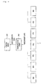
Fig. 1 is a block diagram illustrating a method for generating system analysis information according to a related art. -
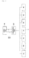
Fig. 2 is a block diagram illustrating a method for generating system analysis information according to an embodiment. -
Fig. 3 is a flowchart illustrating a method for generating system analysis information according to an embodiment. -
Fig. 4 is a block diagram illustrating a communication system according to an embodiment. -
Fig. 5 is a block diagram illustrating a communication system, and a reception side line and a transmission side line between a control device and a communication device according to another embodiment. -
Fig. 6 is a block diagram illustrating a communication system and a plurality of lines between a communication device and a remote terminal unit (RTU) according to another embodiment. -
Fig. 7 is a block diagram illustrating a communication system, a circuit breaker in an RTU, and a DC on-off switch according to another embodiment. - Hereinafter, the embodiments will now be described in detail with reference to the accompanying drawings. However, the disclosure cannot be limited to the embodiment in which the idea of the disclosure is presented, and another embodiment included within range of idea of another backward disclosure or the present disclosure may be easily proposed by addition, change, deletion and the like of another element.
- In the following description, detailed descriptions of well-known functions or constructions will be omitted since they would obscure the invention in unnecessary detail. Moreover, numerals (e.g., first, second, etc.) in the description are used only to distinguish one element from another.
- The terms used in this specification were selected to include current, widely-used general terms. In certain cases, a term may be one that was arbitrarily established by the applicant. In such cases, the meaning of the term will be defined in the relevant portion of the detailed description. As such, the terms used in the specification are not to be defined simply by the name of the terms but are to be defined based on the meanings of the terms as well as the overall description of the present disclosure.
- It will be understood that when an element is referred to as being "connected" or "coupled" to another element, it may be directly connected or coupled to the other element or intervening elements may be present in between unless otherwise specified.
- Throughout this specification, when an element is referred to as "including" a component, it does not preclude another component but may further include the other component unless the context clearly indicates otherwise.
- Hereinafter, embodiments of the present invention will be described in detail with reference to the accompanying drawings. It should be noted that the same reference numerals are used to designate the same or similar elements throughout the drawings.
-
Fig. 2 is a block configuration illustrating a method for generating system analysis information according to an embodiment. - As illustrated in
Fig. 2 , a communication system may include a first remote terminal unit (RTU) 301 and acontrol device 100. Thecontrol device 100 may include a signalquality determining unit 102 and acontrol unit 103. - Referring to
Fig. 2 , the signalquality determining unit 102 may obtain an "OPEN" state signal and signal quality data including quality information of "SUSPECT", which are output from theRTU 301. - When the signal quality data of "SUSPECT" is obtained, the signal
quality determining unit 102 may correct the signal quality data according to a preset condition. - An example of the present condition may include whether a circuit breaker (not illustrated) in the
first RTU 301 is opened and a description thereabout will be provided with reference toFigs. 3 to 7 . - A description is provided with reference to
Fig. 2 again. - The signal
quality determining unit 102 may transmit the corrected signal quality data and the "OPEN" state signal to thecontrol unit 103. - When the corrected signal quality data and the state signal are received, the
control unit 103 may perform state estimation on thefirst RTU 301 on the basis of the corrected signal quality data and the state signal. - In more detail, the
control unit 103 may generate state estimation data for thefirst RTU 301 in response to the corrected signal quality data and the state signal. - When the state estimation data for the
first RTU 301 is generated, thecontrol unit 103 may perform system analysis on the basis of the state estimation data for each RTU. - In more detail, the
control unit 103 may generate the system analysis information on the basis of the "OPEN" state signal output from thefirst RTU 301 and the corrected signal quality data output from the signalquality determining unit 102. -
Fig. 3 is a flowchart illustrating a method for generating system analysis information according to an embodiment. - Referring to
Fig. 3 , the control device 100 (ofFig. 1 ) (or thecontrol device 100 ofFig. 2 ) receives a state signal including state information on each RTU from a plurality of RTUs (operation S101). - In more detail, the signal quality determining unit 102 (of
Fig. 2 ) in thecontrol device 100 may receive the state signal of each RTU from the plurality of RTUs. - When receiving the state signal from each RTU, the signal
quality determining unit 102 obtains the signal quality data for each received state signal (operation S103). - As an example of obtaining the signal quality data, the signal
quality determining unit 102 may obtain the signal quality data through a communication device 200 (ofFig. 4 ) to be described later in the communication system. However, the example of obtaining the signal quality data is not limited thereto. - Once obtaining the signal quality data, the signal
quality determining unit 102 corrects the signal quality data according to a preset condition to generate the corrected signal quality data (operation S105). - In detail, the signal
quality determining unit 102 may further determine whether the signal quality data is "Good" or "suspect" according to the preset condition, and generate the corrected signal quality data on the basis thereof. - The preset condition may be diversely modified according to embodiments.
- According to an embodiment, the signal quality data may be corrected by distinguishing a system-separated facility from a system. For example, when all circuit breakers in the system are closed, presence of the facility separated from the system may be determined to be faulty.
- According to an embodiment, the signal quality data may be corrected by distinguishing a voltage-applied facility from open facilities. For example, when there is a facility in which a circuit breaker that connects a generator to a load is in an open state, but the generator or the load is in a voltage-applied (i.e. driven) state, the facility may be determined to be faulty.
- According to an embodiment, the signal quality data may be corrected on the basis of a configuration of a circuit breaker and a disconnecting switch. Since the circuit breaker and the disconnecting switch are typically driven in the same state, a case having different configurations is searched. For example, when the circuit breaker is closed, the disconnecting switch is to be closed, and when the circuit breaker is opened, the disconnecting switch is also to be opened. Accordingly, a facility having a different configuration therefrom may be determined to be faulty.
- According to an embodiment, the signal quality data may be corrected by distinguishing a facility having different line impedances of multi-lines. Typically, the line impedances of the multi-lines are the same. Accordingly, the facility having the different impedances may be determined to be faulty.
- According to an embodiment, when measurement data is 0 but a state estimation value exists, the signal quality data may be corrected. The case where the measurement data is 0 but the state estimation value exists may be determined to be faulty.
- According to an embodiment, when the state estimation value is 0 but the measurement data exists, the signal quality data may be corrected. The case where the state estimation value is 0 but the measurement data exists may be determined to be faulty.
- According to an embodiment, signal quality data of an area, in which amounts of power influx and outflux through buses are different, may be corrected. The case where the amounts of influx and outflux are different may be determined to be faulty.
- According to an embodiment, when flux values of power flowing from one end and flowing into the other end have a large difference in addition to a loss, the signal quality data may be corrected.
- Data obtained by the above-described embodiments or obtained from a facility or a line determined as faulty is not used for system analysis. Accordingly, the signal
quality determining unit 102 may correct the above-described data. For example, the signal quality data of "good" may be corrected to that of "suspect" - When the signal quality data is corrected, the signal
quality determining unit 102 may transmit the corrected signal quality data to thecontrol unit 103. - When receiving the corrected signal quality data, the
control unit 103 generates state estimation data for each RTU on the basis of the corrected signal quality data and the state signal (S107). - When the state estimation data for each RTU is generated, the
control unit 103 generates the system analysis information, which is analysis information on all the RTUs, on the basis of the generated state estimation data (operations S109). -
Fig. 4 is a block diagram illustrating a communication system according to an embodiment. - As illustrated in
Fig. 4 , the communication system may include acontrol device 100, acommunication device 200, and at least oneRTU 3. - The
control device 100 may include a signal quality determining unit 102 (ofFig. 3 ) and acontrol unit 103. - The
communication device 200 may receive a state signal from the at least oneRTU 3. In addition, thecommunication device 200 may generate signal quality data including trust information on at least the one received state signal. - The
communication device 200 may transmit the received state signal and signal quality data to thecontrol device 100. - As a first example of generating the state estimation data, the control device 100 (or the signal quality determining unit in the control device) may correct the received signal quality data according to a preset condition, and generate the state estimation data based on the corrected signal quality data and the state signal.
- In addition, as a second example of generating the state estimation data, the
control device 100 generates first state estimation data according to the state signal before correcting the received signal quality data, corrects the signal quality data according to the preset condition, and then modifies the previously generated state estimation data in response to the corrected signal quality data to generate second state estimation data. - Hereinafter, a description will be provided about an example of a method for correcting the signal quality data according to the preset condition with reference to
Figs. 4 to 7 . - A first example of correcting the signal quality data will be described with reference to
Fig. 4 . - As illustrated in
Fig. 4 , an example of the state signal output from eachRTU 3 to thecommunication device 200 may include measurement data. - Referring to
Fig. 4 , thecontrol device 100 may obtain the measurement data and signal quality data through thecommunication device 200. - When the measurement data and the signal quality data are obtained, the
control device 100 may generate the state estimation data on the basis of the measurement data, correct the signal quality data according to a preset condition, and modify the generated state estimation data in response to the corrected signal quality data. - When the state estimation data is generated by the
control unit 103 in thecontrol device 100, the signalquality determining unit 102 in thecontrol device 100 may correct the obtained signal quality data according to a preset first condition. - As an example of correcting the signal quality data according to the first condition, when the generated state estimation data is not 0 in a state where the measurement data output from each
RTU 3 is determined as 0, the signalquality determining unit 102 may determine that the measurement data includes an error, and may correct the signal quality data to "SUSPECT" including information that the measurement data includes the error. When the signal quality data is changed to "SUSPECT", the signalquality determining unit 102 may transmit the corrected signal quality data to thecontrol unit 103. - When the corrected signal quality data is transmitted, the
control unit 103 may change the generated state estimation data in response to the information of "SUSPECT" that the measurement data includes the error. - A second example of correcting the signal quality data will described with reference to
Fig. 4 . - Unlike the first example, when the state estimation data is generated by the
control unit 103 in thecontrol device 100, the signalquality determining unit 102 in thecontrol device 100 may correct the obtained signal quality data according to a preset second condition. - As an example of correcting the signal quality data according to the second condition, when the generated state estimation data is determined as 0 in a state where the measurement data output from each
RTU 3 is not determined as 0, the signalquality determining unit 102 may determine that the measurement data includes an error, and may correct the signal quality data to "SUSPECT" including information that the measurement data includes the error. - When the signal quality data is changed to "SUSPECT", the signal
quality determining unit 102 may transmit the corrected signal quality data to thecontrol unit 103. - When the corrected signal quality data is transmitted, the
control unit 103 may change the generated state estimation data in response to the information of "SUSPECT" that the measurement data includes an error. - Third to fifth examples of correcting the signal quality data will be described in detail with reference to
Fig. 5 . - As illustrated in
Fig. 5 , atransmission side line 202 through which data is output from thecontrol device 100 to thecommunication device 200 and areception side line 201 through which data is received by thecontrol data 100 from thecommunication data 200 may be disposed between thecontrol device 100 andcommunication device 200. - When the state estimation data is generated by the
control unit 103 in thecontrol device 100, the signalquality determining unit 102 in thecontrol device 100 may correct the obtained signal quality data according to a preset third condition. - As an example of correcting the signal quality data according to the third condition, when it is determined that a first data amount received by the
control device 100 through thereception side line 201 is not the same as a second data amount output from thecontrol device 100 through thetransmission side line 202, the signalquality determining unit 102 may determine that the measurement data includes an error and correct the signal quality data to information of "SUSPECT", which includes information that the measurement data includes the error. When the signal quality data is changed to "SUSPECT", the signalquality determining unit 102 may transmit the corrected signal quality data to thecontrol unit 103. - When the corrected signal quality data is transmitted, the
control unit 103 may change the generated state estimation data in response to the information of "SUSPECT" that the measurement data includes the error. - As a fourth example of correcting the signal quality data, referring to
Fig. 5 , the signalquality determining unit 102 may correct the obtained signal quality data according to a preset fourth condition. - A first data amount output from the
control device 100 to thecommunication device 200 through thetransmission side line 202 and a second data amount received by thecontrol device 100 through thereception side line 201 may be transmitted through thetransmission side line 202 andreception side line 201, and then received by thecontrol device 100 or output to thecommunication device 200 in a state where a loss occurs in each data. - As an example of correcting the signal quality data according to the fourth condition, when it is determined that the first data amount received by the
control device 100 through thereception side line 201 in the state where the loss occurs is different, by a preset data amount or greater, from a second data amount output by thecontrol device 100 through thetransmission side line 202 in a state where the loss occurs, the signalquality determining unit 102 may determine that the measurement data includes an error and correct the signal quality data to information of "SUSPECT", which includes information that the measurement data includes the error. - When the signal quality data is changed to "SUSPECT", the signal
quality determining unit 102 may transmit the corrected signal quality data to thecontrol unit 103. When the corrected signal quality data is transmitted, thecontrol unit 103 may change the generated state estimation data in response to the information of "SUSPECT" that the measurement data includes the error. - As a fifth example of correcting the signal quality data, referring to
Fig. 6 , the signalquality determining unit 102 may correct the obtained signal quality data according to a preset fifth condition. - As illustrated in
Fig. 6 , first tothird lines communication device 200 and eachRTU 3 may have a line impedance (or resistance) of R. - Referring to
Fig. 6 , the first tothird lines - In other words, in a case where the line impedance (or resistance) values R1, R2, and R2 of the first to
third lines quality determining unit 102 in thecontrol device 100 may determine that the measurement data include the error and correct the signal quality data to "SUSPECT", which includes information that the measurement data include the error. When the signal quality data is changed to "SUSPECT", the signalquality determining unit 102 may transmit the corrected signal quality data to thecontrol unit 103. When the corrected signal quality data is transmitted, thecontrol unit 103 may change the generated state estimation data in response to the information of "SUSPECT" that the measurement data includes the error. - Sixth to eighth examples of correcting the signal quality data will be described in detail with reference to
Fig. 7 . - Referring to
Fig. 7 , eachRTU 3 in thecommunication device 200 may be driven (i.e. turned ON, or voltage-applied) according to a control of thecontrol device 100 or an external signal, or power thereof may be turned OFF. - Each
RTU 3 may include acircuit breaker 301 and a DC on-off switch 302. - The
circuit breaker 301 and the DC on-off switch 302 may be in an OPEN state or CLOSE state (i.e. connected state), and the state of the circuit breaker is the same as that of the DC on-off switch 302. - The signal
quality determining unit 102 in thecontrol device 100 may determine whether thecircuit breaker 301 and the DC on-off switch 302 are open or connected. - In addition, the
control device 100 may transmit a connection command for enabling eachcircuit breaker 301 to be changed to a connection state, and eachcircuit breaker 301 receiving the connection command may be connected according to the connection command to drive (ON) theRTU 3 including eachcircuit breaker 301, and may connect a system (i.e. the control device and the communication device) and eachRTU 3. - Furthermore, when the state estimation data is generated by the
control unit 103 in thecontrol device 100, the signalquality determining unit 102 in thecontrol device 100 may correct the obtained signal quality data according to a preset sixth condition. - As an example of correcting the signal quality data according to the sixth condition, when the
specific RTU 3 is determined to be disconnected from the control device and communication device in a state where all thecircuit breakers 301 of the RTUs are connected, the signalquality determining unit 102 may determine that the measurement data output from a correspondingspecific RTU 3 includes an error and may correct the signal quality data to "SUSPECT", which includes information that the measurement data include the error. - As a seventh example of correcting the signal quality data, when the state estimation data is generated by the
control unit 103 in thecontrol device 100, the signalquality determining unit 102 in thecontrol device 100 may correct the obtained signal quality data according to a preset seventh condition. - As an example of correcting the signal quality data according to the seventh condition, when the
specific RTU 3 is connected to the control device and communication device in a state where all thecircuit breakers 301 of the RTUs are OPEN, the signalquality determining unit 102 may determine that the measurement data output from a correspondingspecific RTU 3 includes an error and may correct the signal quality data to "SUSPECT", which includes information that the measurement data include the error. - As an eighth example of correcting the signal quality data, when the state estimation data is generated by the
control unit 103 in thecontrol device 100, the signalquality determining unit 102 in thecontrol device 100 may correct the obtained signal quality data according to a preset eighth condition. - As an example of correcting the signal quality data according to the eighth condition, when a state (e.g. OPEN or CLOSE) of the
circuit breaker 301 in aspecific RTU 3 is different from a state (e.g. OPEN or CLOSE) of the DC on-off switch 302 in thespecific RTU 3, the signalquality determining unit 102 may determine that the measurement data output from the correspondingspecific RTU 3 includes an error and correct the signal quality data to "SUSPECT", which includes information that the measurement data includes the error. - For the sixth to eighth examples, when the signal quality data is changed to "SUSPECT", the signal
quality determining unit 102 may transmit the corrected signal quality data to thecontrol unit 103. - When the corrected signal quality data is transmitted, the
control unit 103 may change the generated state estimation data in response to the information of "SUSPECT" that the measurement data includes the error. - According to an embodiment, the above-described method may be implemented as a processor-readable code on a medium with a program recorded thereon. Examples of the computer readable recording medium include a read-only memory (ROM), random-access memory (RAM), CD-ROMs, magnetic tapes, floppy disks, and optical data storage devices, and also include carrier waves (such as data transmission through the Internet).
- According to the operation method of the communication system according to an embodiment may trust matching of each piece of signal quality data and accordingly, improve reliability and matching for a state signal obtained from each RTU.
- As can be seen from the foregoing, the above-described embodiments are not limited to the configurations and methods of the embodiments described above, but the entirety of or a part of the embodiments may be configured to be selectively combined such that various modifications of the embodiments can be implemented.
- Although embodiments have been described with reference to a number of illustrative embodiments thereof, it should be understood that numerous other modifications and embodiments can be devised by those skilled in the art that will fall within the spirit and scope of the principles of this disclosure. More particularly, various variations and modifications are possible in the component parts and/or arrangements of the subject combination arrangement within the scope of the disclosure, the drawings and the appended claims. In addition to variations and modifications in the component parts and/or arrangements, alternative uses will also be apparent to those skilled in the art.
Claims (14)
- A communication system comprising:a communication device receiving a state signal from at least one remote terminal unit (RTU), generating signal quality data for the state signal, and transmitting, to a control device, the generated signal quality data and the received state signal; andthe control device generating state estimation data for each of the at least one RTU on a basis of the state signal received from the communication device, correcting the signal quality data transmitted from the communication device according to at least one preset condition, and changing the generated state estimation data on a basis of the corrected signal quality data and the received state signal.
- The communication system according to claim 1, wherein the condition comprises a case where measurement data of the state signal is not determined to be 0 in a state where the generated state estimation data is 0.
- The communication system according to claim 1, wherein the condition comprises a case where measurement data of the state signal is determined to be 0 in a state where the generated state estimation data is not 0.
- The communication system according to claim 1, wherein the condition comprises a case where a first data amount received by the control device from the communication device is not same as a second amount output from the control device to the communication device.
- The communication system according to claim 4, wherein the condition further comprises a case where the first data amount and the second data amount have a difference by a preset data amount or more in a state where a loss occurs in the first and second data amounts.
- The communication system according to claim 1, where at least one line is disposed between each of the at least one RTU and the communication device, and
the condition comprises a case where each impedance value of the at least one line is different from each other. - The communication system according to claim 1, wherein each of the at least one RTU comprises a circuit breaker that connects or disconnects each of the at least one RTU to or from the communication device according to whether to be open or closed,
the condition comprises a case where a specific RTU is determined to be disconnected from the communication device in a state where the circuit breaker of the at least one RTU is connected, and
the control device changes the state estimation data for the specific RTU. - The communication system according to claim 1, wherein each of the at least one RTU comprises a circuit breaker that connects or disconnects each of the at least one RTU to or from the communication device according to whether to be open or closed,
the condition comprises a case where a specific RTU is determined to be connected to the communication device in a state where the circuit breaker of the at least one RTU is open, and
the control device changes the state estimation data for the specific RTU. - The communication system according to claim 1, wherein each of the at least one RTU comprises a connected or opened circuit breaker and DC on-off switch, and
the condition comprises a case where a connected or open state of the circuit breaker comprised in a specific RTU is different from that of the DC on-off switch comprised in the specific RTU. - An operating method of a communication system, the operating method comprising:receiving a state signal from at least one RTU;generating signal quality data for the state signal;generating state estimation data for each of the at least one RTU on a basis of the state signal;correcting the signal quality data according to at least one preset condition; andchanging the generated state estimation data on a basis of the corrected signal quality data and the received state signal.
- The operating method according to claim 10, wherein the condition comprises a case where measurement data of the state signal is not determined to be 0 in a state where the generated state estimation data is 0.
- The operating method according to claim 10, wherein the condition comprises a case where measurement data of the state signal is determined to be 0 in a state where the generated state estimation data is not 0.
- The operating method according to claim 10, wherein the condition comprises a case where a first data amount received by the control device from the communication device is not same as a second data amount output from the control device to the communication device.
- The operating method according to claim 13, wherein the condition further comprises a case where the first data amount and the second data amount are different by a preset data mount or more in a state where a loss occurs in the first and second data amounts.
Applications Claiming Priority (1)
| Application Number | Priority Date | Filing Date | Title |
|---|---|---|---|
| KR1020150054783A KR101660166B1 (en) | 2015-04-17 | 2015-04-17 | Communication system |
Publications (2)
| Publication Number | Publication Date |
|---|---|
| EP3082221A1 true EP3082221A1 (en) | 2016-10-19 |
| EP3082221B1 EP3082221B1 (en) | 2019-05-22 |
Family
ID=55310632
Family Applications (1)
| Application Number | Title | Priority Date | Filing Date |
|---|---|---|---|
| EP16151538.2A Active EP3082221B1 (en) | 2015-04-17 | 2016-01-15 | Communication system and operating method thereof |
Country Status (5)
| Country | Link |
|---|---|
| US (1) | US10444736B2 (en) |
| EP (1) | EP3082221B1 (en) |
| KR (1) | KR101660166B1 (en) |
| CN (1) | CN106059784B (en) |
| ES (1) | ES2737980T3 (en) |
Families Citing this family (2)
| Publication number | Priority date | Publication date | Assignee | Title |
|---|---|---|---|---|
| KR102803421B1 (en) | 2024-09-03 | 2025-05-08 | (주)우현시스템 | System for Performing Communication Using Heating Line |
| KR102803424B1 (en) | 2024-09-20 | 2025-05-08 | (주)우현시스템 | System for Performing Communication Using Power Line |
Citations (5)
| Publication number | Priority date | Publication date | Assignee | Title |
|---|---|---|---|---|
| US20090254655A1 (en) * | 2008-04-04 | 2009-10-08 | Beau Kidwell | Generation and Control of Network Events and Conversion to SCADA Protocol Data Types |
| US20110153108A1 (en) * | 2009-12-18 | 2011-06-23 | Electronics And Telecommunications Research Institute | Method and device for remote power management |
| EP2632007A1 (en) * | 2012-02-22 | 2013-08-28 | LSIS Co., Ltd. | Apparatus and method for correcting error of acquired data |
| US20130311800A1 (en) * | 2012-05-21 | 2013-11-21 | Fuji Xerox Co., Ltd. | Information processing system and method, and non-transitory computer readable medium |
| US20150025700A1 (en) * | 2013-07-18 | 2015-01-22 | Electronics And Telecommunications Research Institute | Apparatus and method remotely monitoring building state |
Family Cites Families (13)
| Publication number | Priority date | Publication date | Assignee | Title |
|---|---|---|---|---|
| DE4442963A1 (en) * | 1994-12-02 | 1996-06-05 | Abb Patent Gmbh | Procedure for initializing and updating a network model |
| JPH09289083A (en) | 1996-04-23 | 1997-11-04 | Matsushita Electric Works Ltd | Lighting control device |
| US6441586B1 (en) * | 2001-03-23 | 2002-08-27 | General Motors Corporation | State of charge prediction method and apparatus for a battery |
| US8185064B2 (en) | 2005-03-17 | 2012-05-22 | Sharp Kabushiki Kaisha | Adaptive modulation control system and wireless communication apparatus |
| JP2007189840A (en) * | 2006-01-13 | 2007-07-26 | Toshiba Corp | Power system stabilizer |
| US8165723B2 (en) | 2006-03-10 | 2012-04-24 | Power Analytics Corporation | Real-time system for verification and monitoring of protective device settings within an electrical power distribution network and automatic correction of deviances found |
| US8854947B2 (en) | 2009-06-15 | 2014-10-07 | Ppc Broadband, Inc. | Device and method for monitoring a communications system |
| CN101924364B (en) * | 2010-07-23 | 2013-05-01 | 清华大学 | Method for estimating nonlinear state of substation-dispatching center two-stage distributed power grid |
| US8738191B2 (en) * | 2010-09-17 | 2014-05-27 | Sarantos K. Aivaliotis | System and method for power grid management |
| US8634965B1 (en) * | 2010-12-03 | 2014-01-21 | Bei Gou | Computer-based method for power system state estimation |
| US9287713B2 (en) * | 2011-08-04 | 2016-03-15 | Siemens Aktiengesellschaft | Topology identification in distribution network with limited measurements |
| JP5895225B2 (en) | 2011-08-24 | 2016-03-30 | パナソニックIpマネジメント株式会社 | Device control system, radio control apparatus, and radio control apparatus program |
| KR101095976B1 (en) * | 2011-09-21 | 2011-12-19 | 주식회사 삼영기술 | Branch line diagnosis system of distribution line using power line communication |
-
2015
- 2015-04-17 KR KR1020150054783A patent/KR101660166B1/en active Active
- 2015-12-15 US US14/970,371 patent/US10444736B2/en active Active
-
2016
- 2016-01-15 ES ES16151538T patent/ES2737980T3/en active Active
- 2016-01-15 EP EP16151538.2A patent/EP3082221B1/en active Active
- 2016-04-07 CN CN201610214415.8A patent/CN106059784B/en active Active
Patent Citations (5)
| Publication number | Priority date | Publication date | Assignee | Title |
|---|---|---|---|---|
| US20090254655A1 (en) * | 2008-04-04 | 2009-10-08 | Beau Kidwell | Generation and Control of Network Events and Conversion to SCADA Protocol Data Types |
| US20110153108A1 (en) * | 2009-12-18 | 2011-06-23 | Electronics And Telecommunications Research Institute | Method and device for remote power management |
| EP2632007A1 (en) * | 2012-02-22 | 2013-08-28 | LSIS Co., Ltd. | Apparatus and method for correcting error of acquired data |
| US20130311800A1 (en) * | 2012-05-21 | 2013-11-21 | Fuji Xerox Co., Ltd. | Information processing system and method, and non-transitory computer readable medium |
| US20150025700A1 (en) * | 2013-07-18 | 2015-01-22 | Electronics And Telecommunications Research Institute | Apparatus and method remotely monitoring building state |
Also Published As
| Publication number | Publication date |
|---|---|
| US10444736B2 (en) | 2019-10-15 |
| ES2737980T3 (en) | 2020-01-17 |
| CN106059784A (en) | 2016-10-26 |
| US20160306342A1 (en) | 2016-10-20 |
| EP3082221B1 (en) | 2019-05-22 |
| CN106059784B (en) | 2019-06-04 |
| KR101660166B1 (en) | 2016-09-30 |
Similar Documents
| Publication | Publication Date | Title |
|---|---|---|
| CN106199329B (en) | Fault location for DC distribution systems | |
| MX2012011015A (en) | Fault location electric power delivery systems. | |
| US10261567B2 (en) | Automatically configurable intelligent electronic device | |
| EP2720332A2 (en) | Online protection coordination for distribution management system | |
| CN107450041B (en) | Current sensor fault diagnosis method and device for synchronous motor and frequency converter | |
| US20160359333A1 (en) | Power distribution system capable of automatic fault detection in a distributed manner and method thereof | |
| CN104007366A (en) | Feeder automation test system with automatic interference input function | |
| AU2019352596A1 (en) | Decentralized false data mitigation for nested microgrids | |
| EP3082221B1 (en) | Communication system and operating method thereof | |
| EP2127063B1 (en) | Adaptive provision of protection function settings of electrical machines | |
| KR102678704B1 (en) | Fault management system for power distribution management system | |
| US20170115645A1 (en) | Apparatus and method for interfacing with supervisory monitoring and control arrangements | |
| KR20180110540A (en) | Apparatus for controlling inverter | |
| US9979673B2 (en) | Communication system and operating method thereof | |
| JP2011176919A (en) | Equipment monitoring device and equipment monitoring system | |
| EP3082222B1 (en) | Communication system and operating method thereof | |
| JP2000175358A (en) | Distribution system monitoring and control system and recording medium storing a program for operating this system | |
| KR101990566B1 (en) | Apparatus and method for acquiring data | |
| US20200292596A1 (en) | Monitoring system | |
| CN111273197B (en) | Electrical equipment testing method and device | |
| KR20210022285A (en) | Apparatus for detecting error of state estimation and method for the same | |
| CN109932593A (en) | The method and apparatus of fault detection for power equipment | |
| JP2000175319A (en) | Power system monitoring device | |
| KR20170126585A (en) | Data Management System | |
| Turc et al. | SCADA System for Monitoring and Reconfiguring an Electrical Distribution Network After a Fault |
Legal Events
| Date | Code | Title | Description |
|---|---|---|---|
| PUAI | Public reference made under article 153(3) epc to a published international application that has entered the european phase |
Free format text: ORIGINAL CODE: 0009012 |
|
| AK | Designated contracting states |
Kind code of ref document: A1 Designated state(s): AL AT BE BG CH CY CZ DE DK EE ES FI FR GB GR HR HU IE IS IT LI LT LU LV MC MK MT NL NO PL PT RO RS SE SI SK SM TR |
|
| AX | Request for extension of the european patent |
Extension state: BA ME |
|
| STAA | Information on the status of an ep patent application or granted ep patent |
Free format text: STATUS: REQUEST FOR EXAMINATION WAS MADE |
|
| 17P | Request for examination filed |
Effective date: 20170418 |
|
| RBV | Designated contracting states (corrected) |
Designated state(s): AL AT BE BG CH CY CZ DE DK EE ES FI FR GB GR HR HU IE IS IT LI LT LU LV MC MK MT NL NO PL PT RO RS SE SI SK SM TR |
|
| STAA | Information on the status of an ep patent application or granted ep patent |
Free format text: STATUS: EXAMINATION IS IN PROGRESS |
|
| 17Q | First examination report despatched |
Effective date: 20180606 |
|
| GRAP | Despatch of communication of intention to grant a patent |
Free format text: ORIGINAL CODE: EPIDOSNIGR1 |
|
| STAA | Information on the status of an ep patent application or granted ep patent |
Free format text: STATUS: GRANT OF PATENT IS INTENDED |
|
| RIC1 | Information provided on ipc code assigned before grant |
Ipc: H02J 3/00 20060101ALN20181115BHEP Ipc: H02J 13/00 20060101AFI20181115BHEP Ipc: G08C 19/00 20060101ALN20181115BHEP |
|
| INTG | Intention to grant announced |
Effective date: 20181212 |
|
| RIC1 | Information provided on ipc code assigned before grant |
Ipc: G08C 19/00 20060101ALN20181203BHEP Ipc: H02J 13/00 20060101AFI20181203BHEP Ipc: H02J 3/00 20060101ALN20181203BHEP |
|
| GRAJ | Information related to disapproval of communication of intention to grant by the applicant or resumption of examination proceedings by the epo deleted |
Free format text: ORIGINAL CODE: EPIDOSDIGR1 |
|
| STAA | Information on the status of an ep patent application or granted ep patent |
Free format text: STATUS: EXAMINATION IS IN PROGRESS |
|
| GRAR | Information related to intention to grant a patent recorded |
Free format text: ORIGINAL CODE: EPIDOSNIGR71 |
|
| GRAS | Grant fee paid |
Free format text: ORIGINAL CODE: EPIDOSNIGR3 |
|
| STAA | Information on the status of an ep patent application or granted ep patent |
Free format text: STATUS: GRANT OF PATENT IS INTENDED |
|
| GRAA | (expected) grant |
Free format text: ORIGINAL CODE: 0009210 |
|
| STAA | Information on the status of an ep patent application or granted ep patent |
Free format text: STATUS: THE PATENT HAS BEEN GRANTED |
|
| INTC | Intention to grant announced (deleted) | ||
| RIC1 | Information provided on ipc code assigned before grant |
Ipc: H02J 13/00 20060101AFI20190410BHEP Ipc: H02J 3/00 20060101ALN20190410BHEP Ipc: G08C 19/00 20060101ALN20190410BHEP |
|
| AK | Designated contracting states |
Kind code of ref document: B1 Designated state(s): AL AT BE BG CH CY CZ DE DK EE ES FI FR GB GR HR HU IE IS IT LI LT LU LV MC MK MT NL NO PL PT RO RS SE SI SK SM TR |
|
| INTG | Intention to grant announced |
Effective date: 20190415 |
|
| REG | Reference to a national code |
Ref country code: GB Ref legal event code: FG4D |
|
| REG | Reference to a national code |
Ref country code: CH Ref legal event code: EP |
|
| REG | Reference to a national code |
Ref country code: IE Ref legal event code: FG4D |
|
| REG | Reference to a national code |
Ref country code: DE Ref legal event code: R096 Ref document number: 602016014142 Country of ref document: DE |
|
| REG | Reference to a national code |
Ref country code: AT Ref legal event code: REF Ref document number: 1137265 Country of ref document: AT Kind code of ref document: T Effective date: 20190615 |
|
| REG | Reference to a national code |
Ref country code: NL Ref legal event code: MP Effective date: 20190522 |
|
| REG | Reference to a national code |
Ref country code: LT Ref legal event code: MG4D |
|
| PG25 | Lapsed in a contracting state [announced via postgrant information from national office to epo] |
Ref country code: LT Free format text: LAPSE BECAUSE OF FAILURE TO SUBMIT A TRANSLATION OF THE DESCRIPTION OR TO PAY THE FEE WITHIN THE PRESCRIBED TIME-LIMIT Effective date: 20190522 Ref country code: NL Free format text: LAPSE BECAUSE OF FAILURE TO SUBMIT A TRANSLATION OF THE DESCRIPTION OR TO PAY THE FEE WITHIN THE PRESCRIBED TIME-LIMIT Effective date: 20190522 Ref country code: PT Free format text: LAPSE BECAUSE OF FAILURE TO SUBMIT A TRANSLATION OF THE DESCRIPTION OR TO PAY THE FEE WITHIN THE PRESCRIBED TIME-LIMIT Effective date: 20190922 Ref country code: AL Free format text: LAPSE BECAUSE OF FAILURE TO SUBMIT A TRANSLATION OF THE DESCRIPTION OR TO PAY THE FEE WITHIN THE PRESCRIBED TIME-LIMIT Effective date: 20190522 Ref country code: FI Free format text: LAPSE BECAUSE OF FAILURE TO SUBMIT A TRANSLATION OF THE DESCRIPTION OR TO PAY THE FEE WITHIN THE PRESCRIBED TIME-LIMIT Effective date: 20190522 Ref country code: SE Free format text: LAPSE BECAUSE OF FAILURE TO SUBMIT A TRANSLATION OF THE DESCRIPTION OR TO PAY THE FEE WITHIN THE PRESCRIBED TIME-LIMIT Effective date: 20190522 Ref country code: NO Free format text: LAPSE BECAUSE OF FAILURE TO SUBMIT A TRANSLATION OF THE DESCRIPTION OR TO PAY THE FEE WITHIN THE PRESCRIBED TIME-LIMIT Effective date: 20190822 Ref country code: HR Free format text: LAPSE BECAUSE OF FAILURE TO SUBMIT A TRANSLATION OF THE DESCRIPTION OR TO PAY THE FEE WITHIN THE PRESCRIBED TIME-LIMIT Effective date: 20190522 |
|
| PG25 | Lapsed in a contracting state [announced via postgrant information from national office to epo] |
Ref country code: GR Free format text: LAPSE BECAUSE OF FAILURE TO SUBMIT A TRANSLATION OF THE DESCRIPTION OR TO PAY THE FEE WITHIN THE PRESCRIBED TIME-LIMIT Effective date: 20190823 Ref country code: RS Free format text: LAPSE BECAUSE OF FAILURE TO SUBMIT A TRANSLATION OF THE DESCRIPTION OR TO PAY THE FEE WITHIN THE PRESCRIBED TIME-LIMIT Effective date: 20190522 Ref country code: LV Free format text: LAPSE BECAUSE OF FAILURE TO SUBMIT A TRANSLATION OF THE DESCRIPTION OR TO PAY THE FEE WITHIN THE PRESCRIBED TIME-LIMIT Effective date: 20190522 Ref country code: BG Free format text: LAPSE BECAUSE OF FAILURE TO SUBMIT A TRANSLATION OF THE DESCRIPTION OR TO PAY THE FEE WITHIN THE PRESCRIBED TIME-LIMIT Effective date: 20190822 |
|
| REG | Reference to a national code |
Ref country code: AT Ref legal event code: MK05 Ref document number: 1137265 Country of ref document: AT Kind code of ref document: T Effective date: 20190522 |
|
| REG | Reference to a national code |
Ref country code: ES Ref legal event code: FG2A Ref document number: 2737980 Country of ref document: ES Kind code of ref document: T3 Effective date: 20200117 |
|
| PG25 | Lapsed in a contracting state [announced via postgrant information from national office to epo] |
Ref country code: SK Free format text: LAPSE BECAUSE OF FAILURE TO SUBMIT A TRANSLATION OF THE DESCRIPTION OR TO PAY THE FEE WITHIN THE PRESCRIBED TIME-LIMIT Effective date: 20190522 Ref country code: CZ Free format text: LAPSE BECAUSE OF FAILURE TO SUBMIT A TRANSLATION OF THE DESCRIPTION OR TO PAY THE FEE WITHIN THE PRESCRIBED TIME-LIMIT Effective date: 20190522 Ref country code: EE Free format text: LAPSE BECAUSE OF FAILURE TO SUBMIT A TRANSLATION OF THE DESCRIPTION OR TO PAY THE FEE WITHIN THE PRESCRIBED TIME-LIMIT Effective date: 20190522 Ref country code: AT Free format text: LAPSE BECAUSE OF FAILURE TO SUBMIT A TRANSLATION OF THE DESCRIPTION OR TO PAY THE FEE WITHIN THE PRESCRIBED TIME-LIMIT Effective date: 20190522 Ref country code: DK Free format text: LAPSE BECAUSE OF FAILURE TO SUBMIT A TRANSLATION OF THE DESCRIPTION OR TO PAY THE FEE WITHIN THE PRESCRIBED TIME-LIMIT Effective date: 20190522 Ref country code: RO Free format text: LAPSE BECAUSE OF FAILURE TO SUBMIT A TRANSLATION OF THE DESCRIPTION OR TO PAY THE FEE WITHIN THE PRESCRIBED TIME-LIMIT Effective date: 20190522 |
|
| REG | Reference to a national code |
Ref country code: DE Ref legal event code: R097 Ref document number: 602016014142 Country of ref document: DE |
|
| PG25 | Lapsed in a contracting state [announced via postgrant information from national office to epo] |
Ref country code: SM Free format text: LAPSE BECAUSE OF FAILURE TO SUBMIT A TRANSLATION OF THE DESCRIPTION OR TO PAY THE FEE WITHIN THE PRESCRIBED TIME-LIMIT Effective date: 20190522 |
|
| PLBE | No opposition filed within time limit |
Free format text: ORIGINAL CODE: 0009261 |
|
| STAA | Information on the status of an ep patent application or granted ep patent |
Free format text: STATUS: NO OPPOSITION FILED WITHIN TIME LIMIT |
|
| PG25 | Lapsed in a contracting state [announced via postgrant information from national office to epo] |
Ref country code: TR Free format text: LAPSE BECAUSE OF FAILURE TO SUBMIT A TRANSLATION OF THE DESCRIPTION OR TO PAY THE FEE WITHIN THE PRESCRIBED TIME-LIMIT Effective date: 20190522 |
|
| 26N | No opposition filed |
Effective date: 20200225 |
|
| PG25 | Lapsed in a contracting state [announced via postgrant information from national office to epo] |
Ref country code: PL Free format text: LAPSE BECAUSE OF FAILURE TO SUBMIT A TRANSLATION OF THE DESCRIPTION OR TO PAY THE FEE WITHIN THE PRESCRIBED TIME-LIMIT Effective date: 20190522 |
|
| PGFP | Annual fee paid to national office [announced via postgrant information from national office to epo] |
Ref country code: DE Payment date: 20200122 Year of fee payment: 5 Ref country code: IT Payment date: 20200128 Year of fee payment: 5 Ref country code: GB Payment date: 20200123 Year of fee payment: 5 Ref country code: ES Payment date: 20200207 Year of fee payment: 5 |
|
| PG25 | Lapsed in a contracting state [announced via postgrant information from national office to epo] |
Ref country code: SI Free format text: LAPSE BECAUSE OF FAILURE TO SUBMIT A TRANSLATION OF THE DESCRIPTION OR TO PAY THE FEE WITHIN THE PRESCRIBED TIME-LIMIT Effective date: 20190522 |
|
| PGFP | Annual fee paid to national office [announced via postgrant information from national office to epo] |
Ref country code: FR Payment date: 20200123 Year of fee payment: 5 |
|
| PG25 | Lapsed in a contracting state [announced via postgrant information from national office to epo] |
Ref country code: MC Free format text: LAPSE BECAUSE OF FAILURE TO SUBMIT A TRANSLATION OF THE DESCRIPTION OR TO PAY THE FEE WITHIN THE PRESCRIBED TIME-LIMIT Effective date: 20190522 |
|
| REG | Reference to a national code |
Ref country code: CH Ref legal event code: PL |
|
| REG | Reference to a national code |
Ref country code: BE Ref legal event code: MM Effective date: 20200131 |
|
| PG25 | Lapsed in a contracting state [announced via postgrant information from national office to epo] |
Ref country code: LU Free format text: LAPSE BECAUSE OF NON-PAYMENT OF DUE FEES Effective date: 20200115 |
|
| PG25 | Lapsed in a contracting state [announced via postgrant information from national office to epo] |
Ref country code: CH Free format text: LAPSE BECAUSE OF NON-PAYMENT OF DUE FEES Effective date: 20200131 Ref country code: LI Free format text: LAPSE BECAUSE OF NON-PAYMENT OF DUE FEES Effective date: 20200131 Ref country code: BE Free format text: LAPSE BECAUSE OF NON-PAYMENT OF DUE FEES Effective date: 20200131 |
|
| PG25 | Lapsed in a contracting state [announced via postgrant information from national office to epo] |
Ref country code: IE Free format text: LAPSE BECAUSE OF NON-PAYMENT OF DUE FEES Effective date: 20200115 |
|
| REG | Reference to a national code |
Ref country code: DE Ref legal event code: R119 Ref document number: 602016014142 Country of ref document: DE |
|
| GBPC | Gb: european patent ceased through non-payment of renewal fee |
Effective date: 20210115 |
|
| PG25 | Lapsed in a contracting state [announced via postgrant information from national office to epo] |
Ref country code: FR Free format text: LAPSE BECAUSE OF NON-PAYMENT OF DUE FEES Effective date: 20210131 |
|
| PG25 | Lapsed in a contracting state [announced via postgrant information from national office to epo] |
Ref country code: GB Free format text: LAPSE BECAUSE OF NON-PAYMENT OF DUE FEES Effective date: 20210115 Ref country code: DE Free format text: LAPSE BECAUSE OF NON-PAYMENT OF DUE FEES Effective date: 20210803 |
|
| REG | Reference to a national code |
Ref country code: ES Ref legal event code: FD2A Effective date: 20220422 |
|
| PG25 | Lapsed in a contracting state [announced via postgrant information from national office to epo] |
Ref country code: IT Free format text: LAPSE BECAUSE OF NON-PAYMENT OF DUE FEES Effective date: 20210115 |
|
| PG25 | Lapsed in a contracting state [announced via postgrant information from national office to epo] |
Ref country code: MT Free format text: LAPSE BECAUSE OF FAILURE TO SUBMIT A TRANSLATION OF THE DESCRIPTION OR TO PAY THE FEE WITHIN THE PRESCRIBED TIME-LIMIT Effective date: 20190522 Ref country code: CY Free format text: LAPSE BECAUSE OF FAILURE TO SUBMIT A TRANSLATION OF THE DESCRIPTION OR TO PAY THE FEE WITHIN THE PRESCRIBED TIME-LIMIT Effective date: 20190522 |
|
| PG25 | Lapsed in a contracting state [announced via postgrant information from national office to epo] |
Ref country code: MK Free format text: LAPSE BECAUSE OF FAILURE TO SUBMIT A TRANSLATION OF THE DESCRIPTION OR TO PAY THE FEE WITHIN THE PRESCRIBED TIME-LIMIT Effective date: 20190522 Ref country code: IS Free format text: LAPSE BECAUSE OF FAILURE TO SUBMIT A TRANSLATION OF THE DESCRIPTION OR TO PAY THE FEE WITHIN THE PRESCRIBED TIME-LIMIT Effective date: 20190922 |
|
| PG25 | Lapsed in a contracting state [announced via postgrant information from national office to epo] |
Ref country code: ES Free format text: LAPSE BECAUSE OF NON-PAYMENT OF DUE FEES Effective date: 20210116 |