EP3082097A1 - Device and method for assessing dynamic stability - Google Patents
Device and method for assessing dynamic stability Download PDFInfo
- Publication number
- EP3082097A1 EP3082097A1 EP16157637.6A EP16157637A EP3082097A1 EP 3082097 A1 EP3082097 A1 EP 3082097A1 EP 16157637 A EP16157637 A EP 16157637A EP 3082097 A1 EP3082097 A1 EP 3082097A1
- Authority
- EP
- European Patent Office
- Prior art keywords
- dynamic stability
- stability assessment
- facility
- power system
- ems
- Prior art date
- Legal status (The legal status is an assumption and is not a legal conclusion. Google has not performed a legal analysis and makes no representation as to the accuracy of the status listed.)
- Withdrawn
Links
Images


Classifications
-
- G—PHYSICS
- G06—COMPUTING OR CALCULATING; COUNTING
- G06Q—INFORMATION AND COMMUNICATION TECHNOLOGY [ICT] SPECIALLY ADAPTED FOR ADMINISTRATIVE, COMMERCIAL, FINANCIAL, MANAGERIAL OR SUPERVISORY PURPOSES; SYSTEMS OR METHODS SPECIALLY ADAPTED FOR ADMINISTRATIVE, COMMERCIAL, FINANCIAL, MANAGERIAL OR SUPERVISORY PURPOSES, NOT OTHERWISE PROVIDED FOR
- G06Q10/00—Administration; Management
- G06Q10/06—Resources, workflows, human or project management; Enterprise or organisation planning; Enterprise or organisation modelling
- G06Q10/063—Operations research, analysis or management
- G06Q10/0639—Performance analysis of employees; Performance analysis of enterprise or organisation operations
- G06Q10/06393—Score-carding, benchmarking or key performance indicator [KPI] analysis
-
- H—ELECTRICITY
- H02—GENERATION; CONVERSION OR DISTRIBUTION OF ELECTRIC POWER
- H02J—ELECTRIC POWER NETWORKS; CIRCUIT ARRANGEMENTS OR SYSTEMS FOR SUPPLYING OR DISTRIBUTING ELECTRIC POWER; SYSTEMS FOR STORING ELECTRIC ENERGY
- H02J3/00—Circuit arrangements for AC mains or AC distribution networks
- H02J3/001—Arrangements for handling faults or abnormalities, e.g. emergencies or contingencies
- H02J3/0014—Arrangements for handling faults or abnormalities, e.g. emergencies or contingencies for preventing or reducing power oscillations in networks
-
- G—PHYSICS
- G01—MEASURING; TESTING
- G01R—MEASURING ELECTRIC VARIABLES; MEASURING MAGNETIC VARIABLES
- G01R19/00—Arrangements for measuring currents or voltages or for indicating presence or sign thereof
- G01R19/25—Arrangements for measuring currents or voltages or for indicating presence or sign thereof using digital measurement techniques
- G01R19/2513—Arrangements for monitoring electric power systems, e.g. power lines or loads; Logging
-
- G—PHYSICS
- G01—MEASURING; TESTING
- G01R—MEASURING ELECTRIC VARIABLES; MEASURING MAGNETIC VARIABLES
- G01R21/00—Arrangements for measuring electric power or power factor
- G01R21/133—Arrangements for measuring electric power or power factor by using digital technique
-
- G—PHYSICS
- G05—CONTROLLING; REGULATING
- G05B—CONTROL OR REGULATING SYSTEMS IN GENERAL; FUNCTIONAL ELEMENTS OF SUCH SYSTEMS; MONITORING OR TESTING ARRANGEMENTS FOR SUCH SYSTEMS OR ELEMENTS
- G05B15/00—Systems controlled by a computer
- G05B15/02—Systems controlled by a computer electric
-
- G—PHYSICS
- G06—COMPUTING OR CALCULATING; COUNTING
- G06Q—INFORMATION AND COMMUNICATION TECHNOLOGY [ICT] SPECIALLY ADAPTED FOR ADMINISTRATIVE, COMMERCIAL, FINANCIAL, MANAGERIAL OR SUPERVISORY PURPOSES; SYSTEMS OR METHODS SPECIALLY ADAPTED FOR ADMINISTRATIVE, COMMERCIAL, FINANCIAL, MANAGERIAL OR SUPERVISORY PURPOSES, NOT OTHERWISE PROVIDED FOR
- G06Q50/00—Information and communication technology [ICT] specially adapted for implementation of business processes of specific business sectors, e.g. utilities or tourism
- G06Q50/06—Energy or water supply
-
- H—ELECTRICITY
- H02—GENERATION; CONVERSION OR DISTRIBUTION OF ELECTRIC POWER
- H02J—ELECTRIC POWER NETWORKS; CIRCUIT ARRANGEMENTS OR SYSTEMS FOR SUPPLYING OR DISTRIBUTING ELECTRIC POWER; SYSTEMS FOR STORING ELECTRIC ENERGY
- H02J3/00—Circuit arrangements for AC mains or AC distribution networks
Definitions
- the present invention relates to a device and method for assessing dynamic stability, and more particularly, to a device and method for assessing dynamic stability that may assess the stability of a power system in real time.
- the stability assessment device of a power system determines whether the power system currently operates stably. Since the instability of the power system may cause blackout, the stability assessment is one of elements that are important in terms of a power system operation.
- Typical offline dynamic stability assessment programs all perform stability assessment based on a bus number.
- Powerflow data in a PTI RAWD format that is core data, to all data required for system analysis, such as dynamic data, contingency data and sequence data are linked with bus numbers based on which stability assessment is performed.
- the bus number based stability assessment method has a limitation in that there is a need to reset all data and scenarios when the bus number is changed.
- the change of a topology, such as bus separation and integration frequently occurs in the power system, and a bus number and the number of buses vary each time the data is extracted.
- the method of assessing the stability of the power system based on the bus number has a difficulty in performing on various cases in real time.
- the bus number based stability assessment method may apply only a specific condition, such as generator dropping, when a specific bus has an accident, and it is difficult to apply a unspecific condition to the stability assessment.
- a specific condition such as generator dropping
- Embodiments provide a new dynamic stability assessment device and method.
- Embodiments also provide a dynamic stability assessment device and method based on a facility name.
- Embodiments also provide a facility name based dynamic stability assessment device and method with which an operation control scheme is combined.
- a dynamic stability assessment device includes an energy management system (EMS); and a dynamic stability assessment system for dynamic stability assessment on a power system of the energy management system.
- the EMS includes an EMS DB that stores power system data for energy management, a display unit configured to output a dynamic stability assessment result, and control unit configured to process the power system data stored in the EMS DB to power system data based on a facility name that includes an operation control scheme, to provide the processed power system data to the dynamic stability assessment system, and to enable an assessment result to be stored and output, the assessment result reflecting the operation control scheme that is received from the dynamic stability assessment system.
- the EMS includes a plurality of facility names with respect to a single facility, and is configured to process to power system data based on any one of the plurality of facility names according to a state of the power system.
- a dynamic stability assessment method includes providing, by an energy management system (EMS), power system data based on a facility name that includes an operation control scheme; reflecting, by the dynamic stability assessment system, the operation control scheme by using the power system data based on the facility name to reflect the operation control scheme to perform an dynamic stability assessment operation; providing, by the dynamic stability assessment system, an assessment result to the EMS; and storing and outputting, by the EMS, the assessment result, wherein the EMS includes a plurality of facility names with respect to a single facility, and is configured to process to power system data based on any one of the plurality of facility names according to a state of the power system.
- EMS energy management system
- Combinations of each block of the accompanying drawing and combinations of each step of a flowchart may also be performed by computer program instructions. Since the computer program instructions may be loaded on the processor of a general-purpose computer, a special-purpose computer or other programmable data processing equipment, the instructions performed by the processor of the computer or other programmable data processing equipment create a means that performs functions described on each block of a drawing or each step of a flowchart.
- the computer program instructions may also be stored in a computer usable or computer readable memory that may aim at the computer or other programmable data processing equipment in order to implement functions in a specific manner, the instructions stored in the computer usable or computer readable memory may also produce an item that includes an instruction means performing functions described on each block of a drawing or each step of a flowchart.
- the computer program instructions may also be loaded on the computer or other programmable data processing equipment.
- instructions operating the computer or other programmable data processing equipment may also provide steps for performing functions described on each block of a drawing and each step of a flowchart.
- each block or each step may represent a portion of a module, a segment or a code that includes one or more executable instructions for performing specific logical function(s). Also, it should be noted that some alternatives may be performed in such a way that functions mentioned at blocks or steps are performed in a different order. For example, two blocks or steps shown one after another may also be performed substantially at the same time or the blocks or steps may also be sometimes performed in a reverse order according to a corresponding function.
- Fig. 1 is a block diagram for explaining a dynamic stability assessment device and method according to an embodiment.
- a dynamic stability assessment device includes an energy management system 100 and a dynamic stability assessment system 200.
- the energy management system 100 transmits data to the dynamic stability assessment system 200 and receives the data from the dynamic stability assessment system 200.
- the energy assessment system 100 provides, to the dynamic stability assessment system 200, power system data based on facility name with which an operation control scheme is combined, receives and stores an assessment result that is output from the dynamic stability assessment system 200.
- the energy management system 100 may also include, tidal current calculation data, dynamic data, a facility name table, a node-bus mapping table, a contingency group, interface data, fault cascading protection data and so on, as power system data obtained for energy management.
- the dynamic stability assessment system 200 may include, power transmission data, monitoring data, prevention modification control data, scenario definition data, calculation parameter data, governor response data, tap-switchover transformer control data, load conversion data, frequency mode analysis data, and so on, as data that a user may input or modify.
- the dynamic stability assessment system 200 may roughly include transient stability assessment (TSA), voltage stability assessment (VSA), and small-signal stability assessment (SSA) according to a factor that determines system stability.
- TSA transient stability assessment
- VSA voltage stability assessment
- SSA small-signal stability assessment
- the data linkage program may be a real-time data link program that is described below.
- the energy management system 100 may include an energy management system (DMA) DB 110, a control unit 120, an input unit 130, and a display unit 140.
- DMA energy management system
- a command or data for the operation of the energy management system 100 may be input to the input unit 130.
- the EMS DB 110 is a DB for calculating and storing the power system data for energy management.
- the control unit 120 includes a data conversion-input processing unit 121 and a data conversion-output processing unit 122.
- the data conversion-input processing unit 121 and the data conversion-output processing unit 122 may use the real-time data link program to transmit and receive data to and from the dynamic stability assessment system 200.
- the data conversion-input processing unit 121 uses the real-time data link program to transmit power system data to the dynamic stability assessment system 200 based on a facility name that includes an operation control method.
- the data conversion-output processing unit 122 receives assessment data output from the dynamic stability assessment system 200 to store the received assessment data in the EMS DB 110.
- the display unit 140 displays the assessment result from the dynamic stability assessment system 200.
- the real-time data link program uses a PTI RAWD data format and furthermore, uses a data format which a unique 65-bit facility name is inserted into the last column for each facility.
- a facility name may include a facility type, an equipment name and a node name.
- the facility name includes ACT, an operation facility name, and an operation control mode.
- the facility name of a transmission line may have LN as the facility type, new Ansung PO SSS1 as the equipment name and node name of a first point, and new Seosan PO SAS1 as the equipment name and node name of a second point, and furthermore it is possible to include ACT GN Taean TP GN1 TRIP as the operation control scheme that drops Taean generator #1 when the power transmission line has a fault.
- the facility name of the power transmission line may be LN new Ansung PO SSS1 new Seosan PO SAS1_ACT GN Taean TP GN1 TRIP.
- the facility name of a transmission line may have LN as the facility type, new Ansung PO SSS1 as the equipment name and node name of a first point, and new Seosan PO SAS1 as the equipment name and node name of a second point, and furthermore it is possible to include ACT SH Asan PO C5S INSERT as the operation control scheme that adds the shunt of Asan PO.
- the facility name of the power transmission line may be LN new Ansung PO SSS1 new Seosan PO SAS1_ACT SH Asan PO C5S INSERT.
- the real-time data link program in the present disclosure uses a unique facility name that includes a facility type, an equipment name, a node name, and an operation control method.
- the dynamic stability assessment system 200 performs dynamic stability assessment after dropping the Taean generator #1 when the power transmission line has a fault or inserting the shunt of the Asan PO according to the operation control scheme.
- power system data is produced by using a unique facility name, a facility name does not vary even when the topology of a power system varies such that the resetting of the power system data is unnecessary.
- the dynamic stability assessment system 200 may reflect the operation control scheme of the facility name to perform dynamic stability assessment even when the dynamic stability assessment system 200 is not separately set, and it is possible to assess dynamic stability in real time even when the topology of the power system varies.
- control unit 120 of the energy management system 100 may generate a plurality of facility names with respect to a single facility according to the control of a user, as in the facility name of the power transmission line as described earlier. That is, it is possible to create a plurality of facility names that has the same facility type, equipment name, and node name but reflects a plurality of operation control methods. For example, a user may create five facility names that reflect five operation control methods, with respect to a single facility.
- a user may set an operation control scheme according to a specific operating condition or managing condition of a power system with the energy management system 100.
- control unit 120 of the energy management system 100 provides, to the dynamic stability assessment system 200, power system data based on the facility name that reflects the operation control scheme according to the operating condition or managing condition of the current power system.
- the dynamic stability assessment system 200 reflects the operation control scheme included in the facility name to perform dynamic stability assessment.
- the dynamic stability assessment system 200 may perform dynamic stability assessment in real time even when the topology of the power system varies.
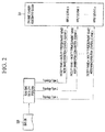
- Fig. 2 illustrates the case where a plurality of facility names is used in a dynamic stability assessment system according to an embodiment.
- a real-time data link program may set n operation control methods with respect to a single facility according to a topology type and applies an appropriate operation control scheme according to a selected topology type to perform dynamic stability assessment.
- topology type 1, topology type 2, and topology type n are set with respect to a single facility in Fig. 2 , and in the case where the topology type 2 is selected, scheme 2 is applied to perform dynamic stability assessment.
- Fig. 3 is a flowchart for explaining a dynamic stability assessment method according to an embodiment.
- control unit 120 of the energy management system 100 receives power system data for real-time dynamic stability assessment and provides, to the dynamic stability assessment system 200, power system data based on facility name that includes an operation control scheme, in step S201.
- the dynamic stability assessment system 200 reflects the operation control scheme to perform dynamic stability assessment calculation in step S202.
- the dynamic stability assessment calculation may be based on at least one or more scenarios that are pre-stored.
- the dynamic stability assessment calculation may be performed through power system data based on a unique facility name that is irrelevant to whether the topology of a power system varies.
- the dynamic stability assessment system 200 When it is possible for the dynamic stability assessment system 200 to determine dynamic stability through input data in step S203, the dynamic stability assessment system 200 performs dynamic stability assessment calculation to provide an assessment result to the energy management system 100 in step S204. If it is difficult to determine dynamic stability, further power system data is received from the control unit 120.
- the energy management system 100 stores and outputs the provided assessment result so that the assessment result is displayed on the display unit 140, in step S205.
- Embodiments may provide a new dynamic stability assessment device and method.
- Embodiments may also provide a dynamic stability assessment device and method based on a facility name.
- Embodiments may also provide a dynamic stability assessment device and method based on a facility name with which an operation control scheme is combined.
Landscapes
- Engineering & Computer Science (AREA)
- Business, Economics & Management (AREA)
- Physics & Mathematics (AREA)
- General Physics & Mathematics (AREA)
- Economics (AREA)
- Power Engineering (AREA)
- Human Resources & Organizations (AREA)
- Health & Medical Sciences (AREA)
- Strategic Management (AREA)
- Marketing (AREA)
- General Business, Economics & Management (AREA)
- Theoretical Computer Science (AREA)
- Tourism & Hospitality (AREA)
- Primary Health Care (AREA)
- Water Supply & Treatment (AREA)
- Public Health (AREA)
- General Health & Medical Sciences (AREA)
- Educational Administration (AREA)
- Entrepreneurship & Innovation (AREA)
- Development Economics (AREA)
- Automation & Control Theory (AREA)
- General Engineering & Computer Science (AREA)
- Game Theory and Decision Science (AREA)
- Operations Research (AREA)
- Quality & Reliability (AREA)
- Supply And Distribution Of Alternating Current (AREA)
- Management, Administration, Business Operations System, And Electronic Commerce (AREA)
- Remote Monitoring And Control Of Power-Distribution Networks (AREA)
Abstract
Description
- The present invention relates to a device and method for assessing dynamic stability, and more particularly, to a device and method for assessing dynamic stability that may assess the stability of a power system in real time.
- The stability assessment device of a power system determines whether the power system currently operates stably. Since the instability of the power system may cause blackout, the stability assessment is one of elements that are important in terms of a power system operation.
- Typical offline dynamic stability assessment programs all perform stability assessment based on a bus number. Powerflow data in a PTI RAWD format that is core data, to all data required for system analysis, such as dynamic data, contingency data and sequence data are linked with bus numbers based on which stability assessment is performed.
- However, the bus number based stability assessment method has a limitation in that there is a need to reset all data and scenarios when the bus number is changed. Actually, the change of a topology, such as bus separation and integration frequently occurs in the power system, and a bus number and the number of buses vary each time the data is extracted. Thus, the method of assessing the stability of the power system based on the bus number has a difficulty in performing on various cases in real time.
- Also, the bus number based stability assessment method may apply only a specific condition, such as generator dropping, when a specific bus has an accident, and it is difficult to apply a unspecific condition to the stability assessment. Especially, in the case where stability is assessed in real time, there is a limitation in that it is difficult to change a setting according to the unspecific condition each time a system topology varies.
- Embodiments provide a new dynamic stability assessment device and method.
- Embodiments also provide a dynamic stability assessment device and method based on a facility name.
- Embodiments also provide a facility name based dynamic stability assessment device and method with which an operation control scheme is combined.
- In one embodiment, a dynamic stability assessment device includes an energy management system (EMS); and a dynamic stability assessment system for dynamic stability assessment on a power system of the energy management system. The EMS includes an EMS DB that stores power system data for energy management, a display unit configured to output a dynamic stability assessment result, and control unit configured to process the power system data stored in the EMS DB to power system data based on a facility name that includes an operation control scheme, to provide the processed power system data to the dynamic stability assessment system, and to enable an assessment result to be stored and output, the assessment result reflecting the operation control scheme that is received from the dynamic stability assessment system. The EMS includes a plurality of facility names with respect to a single facility, and is configured to process to power system data based on any one of the plurality of facility names according to a state of the power system.
- In another embodiment, a dynamic stability assessment method includes providing, by an energy management system (EMS), power system data based on a facility name that includes an operation control scheme; reflecting, by the dynamic stability assessment system, the operation control scheme by using the power system data based on the facility name to reflect the operation control scheme to perform an dynamic stability assessment operation; providing, by the dynamic stability assessment system, an assessment result to the EMS; and storing and outputting, by the EMS, the assessment result, wherein the EMS includes a plurality of facility names with respect to a single facility, and is configured to process to power system data based on any one of the plurality of facility names according to a state of the power system.
-
-
Fig. 1 is a block diagram for explaining a dynamic stability assessment device and method according to an embodiment. -
Fig. 2 illustrates the case where a plurality of facility names is used in a dynamic stability assessment system according to an embodiment. -
Fig. 3 is a flowchart for explaining a dynamic stability assessment method according to an embodiment. - Some embodiments are described below in more detail with reference to the accompanying drawings. Since the suffixes "module" and "unit" for components used in the following description are given and interchanged for easiness in making the present disclosure, they do not have distinct meanings or functions.
- The effects and features of the inventive concept, and implementation methods thereof will be clarified through following embodiments below described in detail with reference to the accompanying drawings. An embodiment may, however, be embodied in different forms and should not be construed as limited to the embodiments set forth herein. Rather, these embodiments are provided to make this disclosure thorough and complete and fully convey the scope of an embodiment to a person skilled in the art. Further, the inventive concept is only defined by scopes of claims. Like reference numerals throughout the disclosure refer to like components.
- When describing embodiments, detailed descriptions related to known functions or configurations will be ruled out in order not to unnecessarily obscure subject matters of the embodiments. In addition, since the terms used herein are defined in consideration of functions in the embodiments, they may vary depending on a user's or operator's intention or practice. Therefore, their definitions need to be made based on details throughout the present disclosure.
- Combinations of each block of the accompanying drawing and combinations of each step of a flowchart may also be performed by computer program instructions. Since the computer program instructions may be loaded on the processor of a general-purpose computer, a special-purpose computer or other programmable data processing equipment, the instructions performed by the processor of the computer or other programmable data processing equipment create a means that performs functions described on each block of a drawing or each step of a flowchart. Since the computer program instructions may also be stored in a computer usable or computer readable memory that may aim at the computer or other programmable data processing equipment in order to implement functions in a specific manner, the instructions stored in the computer usable or computer readable memory may also produce an item that includes an instruction means performing functions described on each block of a drawing or each step of a flowchart. The computer program instructions may also be loaded on the computer or other programmable data processing equipment. Thus, since a series of operation steps are performed on the computer or other programmable data processing equipment to create processes executed by a computer, instructions operating the computer or other programmable data processing equipment may also provide steps for performing functions described on each block of a drawing and each step of a flowchart.
- Also, each block or each step may represent a portion of a module, a segment or a code that includes one or more executable instructions for performing specific logical function(s). Also, it should be noted that some alternatives may be performed in such a way that functions mentioned at blocks or steps are performed in a different order. For example, two blocks or steps shown one after another may also be performed substantially at the same time or the blocks or steps may also be sometimes performed in a reverse order according to a corresponding function.
-
Fig. 1 is a block diagram for explaining a dynamic stability assessment device and method according to an embodiment. - Referring to
Fig. 1 , a dynamic stability assessment device according to an embodiment includes anenergy management system 100 and a dynamicstability assessment system 200. - The
energy management system 100 transmits data to the dynamicstability assessment system 200 and receives the data from the dynamicstability assessment system 200. Theenergy assessment system 100 provides, to the dynamicstability assessment system 200, power system data based on facility name with which an operation control scheme is combined, receives and stores an assessment result that is output from the dynamicstability assessment system 200. - For example, the
energy management system 100 may also include, tidal current calculation data, dynamic data, a facility name table, a node-bus mapping table, a contingency group, interface data, fault cascading protection data and so on, as power system data obtained for energy management. - The dynamic
stability assessment system 200 may include, power transmission data, monitoring data, prevention modification control data, scenario definition data, calculation parameter data, governor response data, tap-switchover transformer control data, load conversion data, frequency mode analysis data, and so on, as data that a user may input or modify. The dynamicstability assessment system 200 may roughly include transient stability assessment (TSA), voltage stability assessment (VSA), and small-signal stability assessment (SSA) according to a factor that determines system stability. - In order for the dynamic
stability assessment system 200 to use power system data from theenergy management system 100 to assess dynamic stability, a data link program is required between theenergy management system 100 and the dynamicstability assessment system 200. The data linkage program may be a real-time data link program that is described below. - The
energy management system 100 may include an energy management system (DMA)DB 110, acontrol unit 120, aninput unit 130, and adisplay unit 140. - A command or data for the operation of the
energy management system 100 may be input to theinput unit 130. - The EMS DB 110 is a DB for calculating and storing the power system data for energy management.
- The
control unit 120 includes a data conversion-input processing unit 121 and a data conversion-output processing unit 122. The data conversion-input processing unit 121 and the data conversion-output processing unit 122 may use the real-time data link program to transmit and receive data to and from the dynamicstability assessment system 200. The data conversion-input processing unit 121 uses the real-time data link program to transmit power system data to the dynamicstability assessment system 200 based on a facility name that includes an operation control method. The data conversion-output processing unit 122 receives assessment data output from the dynamicstability assessment system 200 to store the received assessment data in the EMSDB 110. - The
display unit 140 displays the assessment result from the dynamicstability assessment system 200. - The real-time data link program uses a PTI RAWD data format and furthermore, uses a data format which a unique 65-bit facility name is inserted into the last column for each facility. For the unique facility name, a facility name may include a facility type, an equipment name and a node name. For the operation control method, the facility name includes ACT, an operation facility name, and an operation control mode.
- For e.g., a specific power transmission line, the facility name of a transmission line may have LN as the facility type, new Ansung PO SSS1 as the equipment name and node name of a first point, and new Seosan PO SAS1 as the equipment name and node name of a second point, and furthermore it is possible to include ACT GN Taean TP GN1 TRIP as the operation control scheme that drops Taean
generator # 1 when the power transmission line has a fault. Thus, the facility name of the power transmission line may be LN new Ansung PO SSS1 new Seosan PO SAS1_ACT GN Taean TP GN1 TRIP. - For e.g., a specific power transmission line, the facility name of a transmission line may have LN as the facility type, new Ansung PO SSS1 as the equipment name and node name of a first point, and new Seosan PO SAS1 as the equipment name and node name of a second point, and furthermore it is possible to include ACT SH Asan PO C5S INSERT as the operation control scheme that adds the shunt of Asan PO. Thus, the facility name of the power transmission line may be LN new Ansung PO SSS1 new Seosan PO SAS1_ACT SH Asan PO C5S INSERT.
- As such, the real-time data link program in the present disclosure uses a unique facility name that includes a facility type, an equipment name, a node name, and an operation control method.
- If the power system data on the specific power transmission line is provided to the dynamic
stability assessment system 200 based on the facility name of the power transmission line, the dynamicstability assessment system 200 performs dynamic stability assessment after dropping theTaean generator # 1 when the power transmission line has a fault or inserting the shunt of the Asan PO according to the operation control scheme. - Since in the embodiment, power system data is produced by using a unique facility name, a facility name does not vary even when the topology of a power system varies such that the resetting of the power system data is unnecessary.
- Also, since in the embodiment, a facility including an operation control scheme is used, the dynamic
stability assessment system 200 may reflect the operation control scheme of the facility name to perform dynamic stability assessment even when the dynamicstability assessment system 200 is not separately set, and it is possible to assess dynamic stability in real time even when the topology of the power system varies. - In the embodiment, the
control unit 120 of theenergy management system 100 may generate a plurality of facility names with respect to a single facility according to the control of a user, as in the facility name of the power transmission line as described earlier. That is, it is possible to create a plurality of facility names that has the same facility type, equipment name, and node name but reflects a plurality of operation control methods. For example, a user may create five facility names that reflect five operation control methods, with respect to a single facility. - In addition, a user may set an operation control scheme according to a specific operating condition or managing condition of a power system with the
energy management system 100. - In this case, the
control unit 120 of theenergy management system 100 provides, to the dynamicstability assessment system 200, power system data based on the facility name that reflects the operation control scheme according to the operating condition or managing condition of the current power system. - The dynamic
stability assessment system 200 reflects the operation control scheme included in the facility name to perform dynamic stability assessment. - Thus, the dynamic
stability assessment system 200 may perform dynamic stability assessment in real time even when the topology of the power system varies. -
Fig. 2 illustrates the case where a plurality of facility names is used in a dynamic stability assessment system according to an embodiment. - As shown in
Fig. 2 , a real-time data link program may set n operation control methods with respect to a single facility according to a topology type and applies an appropriate operation control scheme according to a selected topology type to perform dynamic stability assessment. - For example,
topology type 1,topology type 2, and topology type n are set with respect to a single facility inFig. 2 , and in the case where thetopology type 2 is selected,scheme 2 is applied to perform dynamic stability assessment. -
Fig. 3 is a flowchart for explaining a dynamic stability assessment method according to an embodiment. - Referring to
Fig. 3 , thecontrol unit 120 of theenergy management system 100 receives power system data for real-time dynamic stability assessment and provides, to the dynamicstability assessment system 200, power system data based on facility name that includes an operation control scheme, in step S201. - The dynamic
stability assessment system 200 reflects the operation control scheme to perform dynamic stability assessment calculation in step S202. The dynamic stability assessment calculation may be based on at least one or more scenarios that are pre-stored. In addition, the dynamic stability assessment calculation may be performed through power system data based on a unique facility name that is irrelevant to whether the topology of a power system varies. - When it is possible for the dynamic
stability assessment system 200 to determine dynamic stability through input data in step S203, the dynamicstability assessment system 200 performs dynamic stability assessment calculation to provide an assessment result to theenergy management system 100 in step S204. If it is difficult to determine dynamic stability, further power system data is received from thecontrol unit 120. - The
energy management system 100 stores and outputs the provided assessment result so that the assessment result is displayed on thedisplay unit 140, in step S205. - Embodiments may provide a new dynamic stability assessment device and method.
- Embodiments may also provide a dynamic stability assessment device and method based on a facility name.
- Embodiments may also provide a dynamic stability assessment device and method based on a facility name with which an operation control scheme is combined.
- The above-described embodiments are not limited to the above-described configuration and method, and some or all of the embodiments may also be selectively combined so that various variations may be implemented.
Claims (13)
- A dynamic stability assessment device comprising:an energy management system (EMS, 100); anda dynamic stability assessment system (200) for dynamic stability assessment on a power system of the energy management system (100),wherein the EMS (100) comprises an EMS DB (110) that stores power system data for energy management, a display unit (140) configured to output a dynamic stability assessment result, and control unit (120) configured to process the power system data stored in the EMS DB (110) to power system data based on a facility name that comprises an operation control scheme, to provide the processed power system data to the dynamic stability assessment system (200), and to enable an assessment result to be stored and output, the assessment result reflecting the operation control scheme that is received from the dynamic stability assessment system (200), andthe EMS (100) comprises a plurality of facility names with respect to a single facility, and is configured to process to power system data based on any one of the plurality of facility names according to a state of the power system.
- The dynamic stability assessment device according to claim 2, wherein a real-time data link program is used for data transmission and reception between the EMS (100) and the dynamic stability assessment system (200).
- The dynamic stability assessment device according to claim 2, wherein the real-time data link program uses a data format into which a unique facility name is inserted, for each facility.
- The dynamic stability assessment device according to claim 3, wherein the unique facility name comprises a facility type, an equipment name, and a node name.
- The dynamic stability assessment device according to claim 1, wherein ACT, an operation facility name, and an operation control mode are added as an operation name for the operation control scheme.
- The dynamic stability assessment device according to claim 1, wherein the dynamic stability assessment system (200) performs dynamic stability assessment after an action according to the operation control scheme is taken.
- The dynamic stability assessment device according to claim 1, wherein the dynamic stability assessment system (200) applies, to at least one pre-stored scenario, power system data based on a facility name that comprises an operation control scheme input from the EMS (100), to perform an assessment operation.
- A dynamic stability assessment method comprising:providing, by an energy management system (EMS, 100), power system data based on a facility name that comprises an operation control scheme;reflecting, by the dynamic stability assessment system (200), the operation control scheme by using the power system data based on the facility name to reflect the operation control scheme to perform an dynamic stability assessment operation;providing, by the dynamic stability assessment system (200), an assessment result to the EMS (100); andstoring and outputting, by the EMS (100), the assessment result,wherein the EMS (100) comprises a plurality of facility names with respect to a single facility, and is configured to process to power system data based on any one of the plurality of facility names according to a state of the power system.
- The dynamic stability assessment method according to claim 8, wherein the dynamic stability assessment operation is performed based on at least one pre-stored scenario.
- The dynamic stability assessment method according to claim 8, further comprising receiving further power system data from the EMS (100), when it is difficult for the dynamic stability assessment system to determine dynamic stability.
- The dynamic stability assessment method according to claim 8, wherein a real-time data link program is used for data transmission and reception between the EMS (100) and the dynamic stability assessment system (200).
- The dynamic stability assessment method according to claim 11, wherein the real-time data link program uses a data format into which a unique facility name is inserted for each facility.
- The dynamic stability assessment method according to claim 12, wherein the unique facility name comprises a facility type, an equipment name, and a node name.
Applications Claiming Priority (1)
| Application Number | Priority Date | Filing Date | Title |
|---|---|---|---|
| KR1020150052030A KR20160122016A (en) | 2015-04-13 | 2015-04-13 | An apparatus and method for establishing a dynamic security assessment |
Publications (1)
| Publication Number | Publication Date |
|---|---|
| EP3082097A1 true EP3082097A1 (en) | 2016-10-19 |
Family
ID=55527261
Family Applications (1)
| Application Number | Title | Priority Date | Filing Date |
|---|---|---|---|
| EP16157637.6A Withdrawn EP3082097A1 (en) | 2015-04-13 | 2016-02-26 | Device and method for assessing dynamic stability |
Country Status (4)
| Country | Link |
|---|---|
| US (1) | US10312682B2 (en) |
| EP (1) | EP3082097A1 (en) |
| KR (1) | KR20160122016A (en) |
| CN (1) | CN106056262A (en) |
Families Citing this family (1)
| Publication number | Priority date | Publication date | Assignee | Title |
|---|---|---|---|---|
| KR20160122016A (en) | 2015-04-13 | 2016-10-21 | 엘에스산전 주식회사 | An apparatus and method for establishing a dynamic security assessment |
Citations (4)
| Publication number | Priority date | Publication date | Assignee | Title |
|---|---|---|---|---|
| US20030200010A1 (en) * | 2002-04-22 | 2003-10-23 | Hsiao-Dong Chiang | Method and system for on-line dynamical screening of electric power system |
| US20140129746A1 (en) * | 2012-11-02 | 2014-05-08 | Accenture Global Services Limited | Real-time data management for a power grid |
| EP2804361A1 (en) * | 2013-05-13 | 2014-11-19 | LSIS Co., Ltd. | Integrated interface system for power-system monitoring and control system |
| EP2857994A1 (en) * | 2013-09-09 | 2015-04-08 | LSIS Co., Ltd. | Data management apparatus and method of energy management system |
Family Cites Families (33)
| Publication number | Priority date | Publication date | Assignee | Title |
|---|---|---|---|---|
| JPH07175515A (en) | 1993-12-17 | 1995-07-14 | Kobe Steel Ltd | Abnormality detecting method, stability calculating method, and operation control method for machine facility and roller mill |
| JPH10143235A (en) | 1996-11-06 | 1998-05-29 | Toshiba Corp | Power system monitoring and control equipment |
| JPH1132433A (en) | 1997-07-08 | 1999-02-02 | Tokyo Electric Power Co Inc:The | Power system voltage stability evaluation device and recording medium storing those programs |
| JP2000252179A (en) | 1999-03-04 | 2000-09-14 | Hitachi Ltd | Semiconductor manufacturing process stabilization support system |
| JP3527919B2 (en) | 1999-12-28 | 2004-05-17 | 東芝システムテクノロジー株式会社 | Power system monitoring control device, power system facility information generation device, and storage medium |
| US7860702B1 (en) * | 2002-09-18 | 2010-12-28 | Peter B. Evans | Assessing distributed energy resources for the energynet |
| EP1861866A4 (en) | 2005-02-25 | 2010-05-26 | Maersk Inc | System and process for improving container flow in a port facility |
| US8131401B2 (en) * | 2006-07-19 | 2012-03-06 | Power Analytics Corporation | Real-time stability indexing for intelligent energy monitoring and management of electrical power network system |
| JP2008158879A (en) | 2006-12-25 | 2008-07-10 | Hitachi Ltd | Evacuation route calculation device, evacuation route calculation method, and evacuation route calculation program |
| US7848897B2 (en) * | 2008-01-30 | 2010-12-07 | Southern Company Services, Inc. | Dynamic real-time power system monitoring |
| US9360910B2 (en) * | 2009-10-30 | 2016-06-07 | Saudi Arabian Oil Company | Systems, computer readable media, and computer programs for enhancing energy efficiency via systematic hybrid inter-processes integration |
| CN101413981B (en) * | 2008-11-27 | 2010-12-08 | 上海交通大学 | Standby reliability test system for power system operation |
| KR100964298B1 (en) | 2009-12-15 | 2010-06-16 | 한국전력거래소 | A network analysis system |
| JP5582831B2 (en) * | 2010-03-11 | 2014-09-03 | 株式会社東芝 | Solar power system |
| US8924033B2 (en) * | 2010-05-12 | 2014-12-30 | Alstom Grid Inc. | Generalized grid security framework |
| US20120213061A1 (en) * | 2011-02-18 | 2012-08-23 | The Hong Kong University Of Science And Technology | Cognitive relay techniques |
| CA2770166C (en) * | 2011-03-06 | 2015-04-21 | Pcn Technology Inc. | Systems and methods of data transmission and management |
| KR101264645B1 (en) | 2011-05-20 | 2013-05-15 | 대우조선해양 주식회사 | Status definition method and control method for wind turbine system |
| KR101197576B1 (en) | 2011-08-17 | 2012-11-06 | 한국전기연구원 | Online Intelligent Special Protection Scheme using PMUPhasor Measurement Units Data in Power Systems |
| JP5616311B2 (en) | 2011-10-31 | 2014-10-29 | 株式会社日立製作所 | System stabilization system and system stabilization method |
| JP6047894B2 (en) | 2012-01-12 | 2016-12-21 | オムロン株式会社 | Simulation device, simulation method, program, and recording medium |
| JP6008695B2 (en) * | 2012-11-01 | 2016-10-19 | 株式会社日立製作所 | Power system facility data model conversion method, power system facility data model conversion device, and power system facility data model conversion program |
| KR20140082867A (en) | 2012-11-26 | 2014-07-03 | 한국수력원자력 주식회사 | System and method for nuclear power plant maintenace effectiveness monitoring |
| KR20140100165A (en) | 2013-02-05 | 2014-08-14 | 한전케이디엔주식회사 | System for visualizing electric energy management and method thereof |
| US9620959B2 (en) * | 2013-03-15 | 2017-04-11 | Accenture Global Services Limited | Enhanced grid reliability through predictive analysis and dynamic action for stable power distribution |
| US10333312B2 (en) * | 2013-06-26 | 2019-06-25 | Schweitzer Engineering Laboratories, Inc. | Distributed control in electric power delivery systems |
| US10642255B2 (en) | 2013-08-30 | 2020-05-05 | Taiwan Semiconductor Manufacturing Company, Ltd. | Component control in semiconductor performance processing with stable product offsets |
| US10025336B2 (en) * | 2013-10-16 | 2018-07-17 | General Electric Company | System and method for analyzing oscillatory stability in electrical power transmission systems |
| KR101569586B1 (en) | 2013-12-18 | 2015-11-17 | 엘에스산전 주식회사 | Apparatus and method for correcting of acquired data |
| CN104008512B (en) * | 2014-06-12 | 2017-02-15 | 国家电网公司 | Online stability evaluation index system of electric power system |
| JP6239754B2 (en) * | 2014-06-30 | 2017-11-29 | 株式会社日立製作所 | Voltage stability monitoring apparatus and method |
| US10132853B2 (en) * | 2015-04-10 | 2018-11-20 | Washington State University | Wide area fault detection method using PMU data |
| KR20160122016A (en) | 2015-04-13 | 2016-10-21 | 엘에스산전 주식회사 | An apparatus and method for establishing a dynamic security assessment |
-
2015
- 2015-04-13 KR KR1020150052030A patent/KR20160122016A/en not_active Ceased
-
2016
- 2016-02-26 EP EP16157637.6A patent/EP3082097A1/en not_active Withdrawn
- 2016-04-05 CN CN201610206768.3A patent/CN106056262A/en active Pending
- 2016-04-12 US US15/097,031 patent/US10312682B2/en active Active
Patent Citations (4)
| Publication number | Priority date | Publication date | Assignee | Title |
|---|---|---|---|---|
| US20030200010A1 (en) * | 2002-04-22 | 2003-10-23 | Hsiao-Dong Chiang | Method and system for on-line dynamical screening of electric power system |
| US20140129746A1 (en) * | 2012-11-02 | 2014-05-08 | Accenture Global Services Limited | Real-time data management for a power grid |
| EP2804361A1 (en) * | 2013-05-13 | 2014-11-19 | LSIS Co., Ltd. | Integrated interface system for power-system monitoring and control system |
| EP2857994A1 (en) * | 2013-09-09 | 2015-04-08 | LSIS Co., Ltd. | Data management apparatus and method of energy management system |
Non-Patent Citations (1)
| Title |
|---|
| RAMANATHAN R ET AL: "BPA's experience of implementing node breaker model for power system operations studies", 2013 48TH INTERNATIONAL UNIVERSITIES' POWER ENGINEERING CONFERENCE (UPEC), IEEE, 2 September 2013 (2013-09-02), pages 1 - 6, XP032778026, DOI: 10.1109/UPEC.2013.6714898 * |
Also Published As
| Publication number | Publication date |
|---|---|
| CN106056262A (en) | 2016-10-26 |
| US10312682B2 (en) | 2019-06-04 |
| KR20160122016A (en) | 2016-10-21 |
| US20160301206A1 (en) | 2016-10-13 |
Similar Documents
| Publication | Publication Date | Title |
|---|---|---|
| US9785170B2 (en) | Dispatcher training simulating device and operation method thereof | |
| US9696694B2 (en) | Parameter setting device | |
| EP2535994A2 (en) | Fault processing system | |
| WO2011052878A1 (en) | Integrated system and method for verifying dcs | |
| CN114779747A (en) | Vehicle fault cause determination system and method | |
| KR102168212B1 (en) | Apparatus and method for application log data processing | |
| CN104361190B (en) | The method and device of empty terminal automation connection in electrical secondary system | |
| US20130214927A1 (en) | Apparatus and method for correcting error of acquired data | |
| US11262733B2 (en) | Method, device, and computer program for configuring an intelligent electronic device | |
| EP3252630A1 (en) | Simulation apparatus and operating method thereof | |
| US10312682B2 (en) | Device and method for assessing dynamic stability | |
| US20200096959A1 (en) | Power system simulation based on snapshot data | |
| CN110707759B (en) | A safety and stability control method for a high proportion of wind power grid | |
| EP3968614A1 (en) | Message processing method and device, electronic equipment, storage medium and program product | |
| KR101720411B1 (en) | An apparatus and method for establishing a dynamic security assessment | |
| US20120221281A1 (en) | Method and apparatus for testing a wind turbine installation | |
| CN115877823B (en) | Test and evaluation method, system, device and equipment for safety and stability control strategy | |
| US7889067B2 (en) | Alarm information processing device and alarm information processing method | |
| EP2887497B1 (en) | Apparatus and method for correcting acquired data | |
| CN111797152A (en) | Data scene generation method and device and computer equipment | |
| KR101475596B1 (en) | dispatcher training system and its control method | |
| KR102283234B1 (en) | Real time ship propulsion system simulation system using MATLAB/SIMULINK | |
| CN113469556A (en) | Method and device for generating work ticket, electronic equipment and storage medium | |
| CN111400118B (en) | Method and system for creating serial port command for online function file | |
| EP2945067B1 (en) | Power system monitoring and control system having thread-dependent calculation monitoring function |
Legal Events
| Date | Code | Title | Description |
|---|---|---|---|
| PUAI | Public reference made under article 153(3) epc to a published international application that has entered the european phase |
Free format text: ORIGINAL CODE: 0009012 |
|
| AK | Designated contracting states |
Kind code of ref document: A1 Designated state(s): AL AT BE BG CH CY CZ DE DK EE ES FI FR GB GR HR HU IE IS IT LI LT LU LV MC MK MT NL NO PL PT RO RS SE SI SK SM TR |
|
| AX | Request for extension of the european patent |
Extension state: BA ME |
|
| STAA | Information on the status of an ep patent application or granted ep patent |
Free format text: STATUS: REQUEST FOR EXAMINATION WAS MADE |
|
| 17P | Request for examination filed |
Effective date: 20170418 |
|
| RBV | Designated contracting states (corrected) |
Designated state(s): AL AT BE BG CH CY CZ DE DK EE ES FI FR GB GR HR HU IE IS IT LI LT LU LV MC MK MT NL NO PL PT RO RS SE SI SK SM TR |
|
| STAA | Information on the status of an ep patent application or granted ep patent |
Free format text: STATUS: EXAMINATION IS IN PROGRESS |
|
| 17Q | First examination report despatched |
Effective date: 20200811 |
|
| STAA | Information on the status of an ep patent application or granted ep patent |
Free format text: STATUS: THE APPLICATION IS DEEMED TO BE WITHDRAWN |
|
| 18D | Application deemed to be withdrawn |
Effective date: 20220503 |