EP3082070A1 - Card reader - Google Patents
Card reader Download PDFInfo
- Publication number
- EP3082070A1 EP3082070A1 EP14869301.3A EP14869301A EP3082070A1 EP 3082070 A1 EP3082070 A1 EP 3082070A1 EP 14869301 A EP14869301 A EP 14869301A EP 3082070 A1 EP3082070 A1 EP 3082070A1
- Authority
- EP
- European Patent Office
- Prior art keywords
- card
- lock member
- gear
- shaft
- motor
- Prior art date
- Legal status (The legal status is an assumption and is not a legal conclusion. Google has not performed a legal analysis and makes no representation as to the accuracy of the status listed.)
- Granted
Links
Images


Classifications
-
- G—PHYSICS
- G06—COMPUTING OR CALCULATING; COUNTING
- G06K—GRAPHICAL DATA READING; PRESENTATION OF DATA; RECORD CARRIERS; HANDLING RECORD CARRIERS
- G06K13/00—Conveying record carriers from one station to another, e.g. from stack to punching mechanism
- G06K13/02—Conveying record carriers from one station to another, e.g. from stack to punching mechanism the record carrier having longitudinal dimension comparable with transverse dimension, e.g. punched card
- G06K13/08—Feeding or discharging cards
- G06K13/085—Feeding or discharging cards using an arrangement for locking the inserted card
-
- G—PHYSICS
- G06—COMPUTING OR CALCULATING; COUNTING
- G06K—GRAPHICAL DATA READING; PRESENTATION OF DATA; RECORD CARRIERS; HANDLING RECORD CARRIERS
- G06K7/00—Methods or arrangements for sensing record carriers, e.g. for reading patterns
- G06K7/0013—Methods or arrangements for sensing record carriers, e.g. for reading patterns by galvanic contacts, e.g. card connectors for ISO-7816 compliant smart cards or memory cards, e.g. SD card readers
- G06K7/0021—Methods or arrangements for sensing record carriers, e.g. for reading patterns by galvanic contacts, e.g. card connectors for ISO-7816 compliant smart cards or memory cards, e.g. SD card readers for reading/sensing record carriers having surface contacts
-
- G—PHYSICS
- G06—COMPUTING OR CALCULATING; COUNTING
- G06K—GRAPHICAL DATA READING; PRESENTATION OF DATA; RECORD CARRIERS; HANDLING RECORD CARRIERS
- G06K7/00—Methods or arrangements for sensing record carriers, e.g. for reading patterns
- G06K7/08—Methods or arrangements for sensing record carriers, e.g. for reading patterns by means detecting the change of an electrostatic or magnetic field, e.g. by detecting change of capacitance between electrodes
- G06K7/082—Methods or arrangements for sensing record carriers, e.g. for reading patterns by means detecting the change of an electrostatic or magnetic field, e.g. by detecting change of capacitance between electrodes using inductive or magnetic sensors
- G06K7/083—Methods or arrangements for sensing record carriers, e.g. for reading patterns by means detecting the change of an electrostatic or magnetic field, e.g. by detecting change of capacitance between electrodes using inductive or magnetic sensors inductive
- G06K7/084—Methods or arrangements for sensing record carriers, e.g. for reading patterns by means detecting the change of an electrostatic or magnetic field, e.g. by detecting change of capacitance between electrodes using inductive or magnetic sensors inductive sensing magnetic material by relative movement detecting flux changes without altering its magnetised state
-
- G—PHYSICS
- G07—CHECKING-DEVICES
- G07F—COIN-FREED OR LIKE APPARATUS
- G07F7/00—Mechanisms actuated by objects other than coins to free or to actuate vending, hiring, coin or paper currency dispensing or refunding apparatus
- G07F7/08—Mechanisms actuated by objects other than coins to free or to actuate vending, hiring, coin or paper currency dispensing or refunding apparatus by coded identity card or credit card or other personal identification means
- G07F7/0873—Details of the card reader
Definitions
- the present invention relates to a card reader structured to read data recorded in a card and to record data in a card.
- a card reader has been widely utilized which is structured to read data recorded in a card and to record data in a card.
- illegal acquisition of a card by a criminal who intentionally clogs the card in an inside of a card reader, i.e., so-called phishing has become a large issue. Therefore, conventionally, a card reader having a card lock mechanism for preventing phishing has been proposed (see, for example, Patent Literature 1).
- the card lock mechanism includes a lock lever for preventing drawing of a card from a card insertion port.
- the lock lever is provided with lock teeth in a substantially triangular shape which is configured to contact with a card for preventing drawing of the card.
- the lock lever is turnably supported by a support pin.
- the lock lever is connected with a motor through a connecting lever, a fan-shaped gear and a reduction gear train.
- the lock lever is turnable by power of the motor between a position where the lock teeth are retreated from a card conveying passage and a position where the lock teeth are contacted with the card.
- the reduction gear train is structured of many gears. Therefore, in the card reader, a reduction gear ratio becomes large in a transmission path of power from the motor to the lock lever and thus, even when a small motor with small output is used, contact pressure of the lock teeth with a card can be secured.
- phishing may be performed by a criminal. Specifically, we have found that phishing may be performed by a criminal so that the criminal inserts a certain tool from a card insertion port to separate the lock lever from a card in a state that the lock teeth are contacted with the card and draws the card from the card insertion port.
- a reduction gear ratio in a transmission path of power from the motor to the lock lever is large and thus, even when a small motor is used, contact pressure of the lock teeth with a card can be secured.
- a reduction gear train is structured of many gears in order to increase a reduction gear ratio in the transmission path of power from the motor to the lock lever. Therefore, in the card reader, even when a small motor is used, the size of the card lock mechanism is large.
- an objective of the present invention is to provide a card reader which is capable of reducing the size of the card lock mechanism and of surely preventing phishing.
- the present invention provides a card reader including a card insertion port into which a card is inserted and from which the card is ejected, a card conveying passage where the card inserted from the card insertion port is conveyed, and a card lock mechanism structured to prevent drawing of the card from the card insertion port when abnormality has been detected in conveyance of the card in the card conveying passage.
- the card lock mechanism includes a motor, a lock member which is formed with a prevention pawl configured to contact with the card for preventing drawing of the card and is moved between a contact position where the prevention pawl is contacted with the card and a retreated position where the prevention pawl is retreated from the card conveying passage by power transmitted from the motor, and a power transmission mechanism structured to transmit power of the motor to the lock member.
- the power transmission mechanism includes a worm gear structured of a screw gear and a helical gear engaged with the screw gear, and the screw gear is disposed on a motor side relative to the helical gear in a transmitting direction of power from the motor to the lock member.
- the power transmission mechanism structured to transmit power of the motor to the lock member includes the worm gear and a reduction gear ratio of the worm gear can be increased. Therefore, according to the present invention, even when the number of gears structuring the power transmission mechanism is reduced, a reduction gear ratio in a transmission path of power from the motor to the lock member can increased. Accordingly, in the present invention, even when a small motor is used, contact pressure of the prevention pawl with a card can be secured. As described above, in the present invention, even when the number of gears structuring the power transmission mechanism is reduced or, even when a small motor is used, contact pressure of the prevention pawl with a card can be secured. Therefore, while securing contact pressure of the prevention pawl with a card, the size of the card lock mechanism can be reduced.
- the worm gear is disposed in the transmission path of power from the motor to the lock member. Therefore, even when a criminal tries to push the lock member in a direction from the contact position to the retreated position by using a certain tool inserted from the card insertion port, the helical gear structuring the worm gear is hardly turned. Accordingly, in the present invention, a situation can be prevented that the prevention pawl is moved until the contact condition of the prevention pawl with a card is released. Therefore, even when a criminal tries to draw a card in a contacted state with the prevention pawl from the card insertion port by using a tool, drawing of the card from the card insertion port can be prevented by operation of the prevention pawl. As a result, in the present invention, phishing can be prevented surely.
- the card reader includes a magnetic head configured to perform at least one of reading of magnetic data recorded in the card and recording of magnetic data to the card, the card reader is structured so that the card formed in a substantially rectangular shape is conveyed in a short-side direction of the card and is processed, the magnetic head is disposed so as to face the card conveying passage from one side in a thickness direction of the card with respect to the card conveying passage, and the lock member is disposed on the one side in the thickness direction of the card with respect to the card conveying passage so that the prevention pawl is contacted with the card from the one side in the thickness direction of the card with respect to the card conveying passage.
- the lock member is disposed so that the prevention pawl is contacted with a face of a card on the side where a magnetic stripe is formed.
- the power transmission mechanism includes the screw gear fixed to an output shaft of the motor, a first rotation shaft to which the helical gear is fixed, a first spur gear which is fixed to the first rotation shaft, a second spur gear which is engaged with the first spur gear, a second rotation shaft by which the second spur gear is relatively turnably held, a third spur gear which is fixed to the second rotation shaft, two gear side pins which are fixed to a side face of the second spur gear so as to protrude in an axial direction of the second rotation shaft, and a shaft side pin which is fixed to the second rotation shaft so as to protrude to both sides in a radial direction of the second rotation shaft and to be capable of contacting with the two gear side pins.
- a pin clutch is structured of the two gear side pins and the shaft side pin, the pin clutch being configured to connect and disconnect power transmission between the second spur gear and the second rotation shaft in a power transmission path between the motor and the lock member.
- the lock member is formed with a teeth part which is engaged with the third spur gear
- the card lock mechanism includes a fixed shaft which turnably holds the lock member or a turnable shaft which is turned together with the lock member, and the lock member is turned with the fixed shaft or the turnable shaft as a center to be moved between the contact position and the retreated position.
- the card lock mechanism includes a fixed shaft which turnably holds the lock member or a turnable shaft which is turned together with the lock member, the lock member is turned with the fixed shaft or the turnable shaft as a center to be moved between the contact position and the retreated position.
- a turning direction of the lock member moved from the retreated position to the contact position is referred to as a first direction
- a first direction when drawing force in an ejecting direction of the card is applied to the card in a state that the prevention pawl is contacted with the card, turning force in the first direction is applied to the lock member, and a tip end of the prevention pawl is formed in a pointed shape so as to stick into the card when drawing force in the ejecting direction of the card is applied to the card in the state that the prevention pawl is contacted with the card.
- the size of the card lock mechanism can be reduced and phishing can be prevented surely.
- Fig. 1 is a perspective view showing a card reader 1 in accordance with an embodiment of the present invention.
- Fig. 2 is a perspective view showing a lower side portion relative to a card conveying passage "W" of a card insertion part 4 shown in Fig. 1 .
- a card reader 1 in this embodiment is a device structured to perform at least one of reading of magnetic data recorded in a card 2 and recording of magnetic data to a card 2.
- the card reader 1 is mounted and used in a predetermined host apparatus such as an ATM (Automated Teller Machine).
- the card reader 1 in this embodiment is operated on the basis of command instructions from the predetermined host apparatus.
- the card reader 1 includes a card insertion part 4 formed with a card insertion port 3 where a card 2 is inserted into and ejected from, and a main body part 5.
- a card conveying passage "W" where a card 2 inserted into the card insertion port 3 is conveyed is formed in an inside of the card reader 1.
- the card conveying passage “W” is formed to be a passage for passing a card 2 which is conveyed from the card insertion port 3 and passed through the card insertion part 4 to the main body part 5. Further, the card reader 1 includes a card lock mechanism 7 for preventing drawing of a card 2 from the card insertion port 3 when abnormal conveyance of the card 2 in the card conveying passage "W" is detected.
- the host apparatus is structured so that, when an abnormal conveyance of a card 2 is detected, the host apparatus determines that abnormality such as a fraudulent act of a criminal has occurred and sends a command instruction for driving the card lock mechanism 7 to the card reader 1.
- example cases that the host apparatus determines that an abnormal conveyance of a card 2 has occurred are as follows. For example, one case is that, when movement of a card 2 is not detected although the host apparatus has outputted a command for conveying a card 2, the host apparatus determines that the card 2 is abnormally stopped and the card 2 has been clogged in a card conveying passage "W". Another case is that a card 2 is moving along the card conveying passage "W" although conveyance of a card 2 is controlled to be stopped.
- the host apparatus is structured so that, when an abnormal situation of the card reader 1 which does not correspond to its command is detected, the host apparatus determines that a fraudulent act by a criminal has been occurred and the card lock mechanism 7 is operated.
- a card 2 is that made of vinyl chloride whose thickness is about 0.7-0.8mm.
- a card 2 in this embodiment is a card with a magnetic stripe in conformity with the international standard (for example, ISO/IEC7811) or JIS standard (for example, JISX6302) and is formed in a substantially rectangular shape whose four corners are rounded.
- a rear face of the card 2 is formed with a magnetic stripe in which magnetic data is to be recorded. Further, an IC chip is incorporated in the card 2.
- a card 2 is conveyed in the "X” direction in Fig. 1 and the like. Specifically, a card 2 is taken in the "X1” direction and the card 2 is ejected in the "X2" direction.
- the "X” direction is a conveying direction of a card 2
- the "X1” direction is a taking-in direction of a card 2
- the "X2" direction is an ejecting direction of the card 2.
- a card 2 is taken into the card reader 1 so that a short-side direction of the card 2 and the "X" direction are coincided with each other.
- the card 2 is conveyed in the card reader 1 so that the short-side direction of the card 2 and the "X" direction are coincided with each other.
- the card reader 1 is structured so as to convey a card 2 in a short-side direction of the card 2 and perform predetermined processing.
- the "Y” direction perpendicular to the "X” direction is a width direction of the card conveying passage “W” and is a longitudinal direction of a card 2 taken into the card reader 1 in a correct posture.
- the "Z” direction in Fig. 1 and the like perpendicular to the "X” direction and the “Y” direction is a height direction in the card conveying passage "W” and is a thickness direction of a card 2 taken into the card reader 1.
- the card reader 1 is disposed so that the "Z" direction and a vertical direction are coincided with each other.
- the "X” direction is referred to as a "front and rear direction”
- the "Y” direction is referred to as a “right and left direction”
- the “Z” direction is referred to as an "upper and lower direction”.
- the "X1" direction side is a “rear (back) side”
- the "X2" direction side is a "front” side
- the "Y1” direction side is a “right” side
- the "Y2” direction side is a “left” side
- the "Z1” direction side is an "upper” side
- the "Z2" direction side is a “lower” side.
- a card insertion part 4 is attached to a front end face of the main body part 5.
- the main body part 5 includes a magnetic head (not shown) configured to perform at least one of reading of magnetic data recorded in a card 2 and recording of magnetic data to a card 2, and IC contact points (not shown) configured to perform data communication with an IC chip incorporated into the card 2.
- the magnetic head is disposed so as to face the card conveying passage "W” from a lower side with respect to the card conveying passage "W". Further, the magnetic head is mounted on a carriage (not shown) which is movable in the right and left direction. The carriage is connected with a carriage drive mechanism 8 and the magnetic head is moved in the right and left direction together with the carriage. Further, the magnetic head is moved up and down between a position where the magnetic head is capable of contacting with a card 2 and a position where the magnetic head is retreated from the card conveying passage "W”.
- the IC contact points are disposed so as to face the card conveying passage "W” from an upper side with respect to the card conveying passage "W”. Further, the IC contact points are fixed to an IC contact block.
- the IC contact block is connected with an IC contact block drive mechanism and the IC contact points are moved up and down between a position where the IC contact points are capable of contacting with a card 2 and a position where the IC contact points are retreated from the card conveying passage "W".
- the main body part 5 includes conveying rollers 10 (see Fig. 1 ) configured to abut with a card 2 and convey the card 2, and pad rollers 11 (see Fig. 2 ) oppositely disposed to the conveying rollers 10.
- the conveying rollers 10 are disposed so as to face the card conveying passage "W" from an upper side.
- the pad rollers 11 are disposed so as to face the card conveying passage "W” from a lower side.
- Fig. 3 is a perspective view showing a state that a lower frame 13 is detached from a state shown in Fig. 2 .
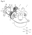
- Fig. 4 is a perspective view showing a card lock mechanism 7 shown in Fig. 3 which is viewed from another direction.
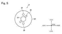
- Fig. 5 is an explanatory schematic view showing a structure of a pin clutch 31 which is disposed between a spur gear 23 and a rotation shaft 24 shown in Fig. 4 .
- the card lock mechanism 7 includes a motor 14, a lock member 15 configured to prevent drawing of a card 2, and a power transmission mechanism 16 structured to transmit power of the motor 14 to the lock member 15.
- the card lock mechanism 7 is disposed to a lower side of the card conveying passage "W".
- the card lock mechanism 7 is, as shown in Fig. 2 , disposed on a lower side with respect to a lower frame 13 which structures a lower face portion of the card conveying passage "W" in the card insertion part 4.
- the lower frame 13 is formed with a passage opening 13a where prevention pawls 35a described below structuring the lock member 15 are passed so as to penetrate in the upper and lower direction.
- the motor 14 is fixed to a support frame 17 so that its output shaft is protruded to an upper side.
- the support frame 17 is fixed to a lower side of the lower frame 13.
- the power transmission mechanism 16 includes a worm gear 20 structured of a screw gear 18 fixed to the output shaft of the motor 14 and a helical gear 19 engaged with the screw gear 18, a rotation shaft 21 as a first rotation shaft to which the helical gear 19 is fixed, a spur gear 22 as a first spur gear which is fixed to the rotation shaft 21, a spur gear 23 as a second spur gear which is engaged with the spur gear 22, a rotation shaft 24 as a second rotation shaft to which the spur gear 23 is relatively rotatably held, and a spur gear 25 as a third spur gear which is fixed to the rotation shaft 24.
- the spur gear 25 is engaged with a teeth part 35b formed on a lock plate 35 described below structuring the lock member 15. Therefore, in a transmitting direction of power from the motor 14 to the lock member 15, when the motor 14 side is referred to as a former stage and the lock member 15 side is referred to as a latter stage, the screw gear 18 is disposed on the former stage (in other words, motor 14 side) relative to the helical gear 19 in the transmitting direction of power from the motor 14 to the lock member 15.
- the rotation shaft 21 is disposed so that its axial direction and the right and left direction are coincided with each other. Further, the rotation shaft 21 is formed in a hollow shape. In other words, the rotation shaft 21 is formed in a long and thin cylindrical tube shape.
- a fixed shaft 28 is inserted on an inner peripheral side of the rotation shaft 21. The fixed shaft 28 is fixed to the support frame 17 so that its axial direction and the right and left direction are coincided with each other.
- the helical gear 19 is fixed to a right end side of the rotation shaft 21 and the spur gear 22 is fixed to a left end side of the rotation shaft 21.
- the rotation shaft 24 is disposed so that its axial direction and the right and left direction are coincided with each other. Further, the rotation shaft 24 is rotatably held by the support frame 17.
- the spur gear 23 is relatively rotatably held by the rotation shaft 24 on a right end side of the rotation shaft 24.
- the spur gear 25 is fixed to a left end side of the rotation shaft 24.
- a left side face of the spur gear 23 is fixed with two gear side pins 29 in a cylindrical shape so as to protrude to the left direction (see Fig. 5 ).
- the two gear side pins 29 are fixed to the spur gear 23 with 180° pitch with the rotation shaft 24 as a center.
- the rotation shaft 24 is fixed with a shaft side pin 30 protruding to both sides in its radial direction (see Fig. 5 ).
- the shaft side pin 30 is fixed to the rotation shaft 24 so as to be capable of contacting with the two gear side pins 29.
- a pin clutch 31 is structured by the two gear side pins 29 and the shaft side pin 30 so that power transmission between the spur gear 23 and the rotation shaft 24 is connected and disconnected in the power transmission path between the motor 14 and the lock member 15.
- the lock member 15 is provided with two lock plates 35 which are formed with prevention pawls 35a configured to contact with a card 2 and prevent drawing of the card 2.
- the lock plate 35 is formed with a teeth part 35b engaging with the spur gear 25 in addition to the prevention pawl 35a.
- the lock plate 35 is formed in a flat plate shape whose thickness direction is the right and left direction.
- a front upper end side of the lock plate 35 is turnably held by a fixed shaft 36 which is fixed to the support frame 17. In other words, the front upper end side of the lock member 15 is turnably held by the fixed shaft 36.
- the fixed shaft 36 is disposed so that its axial direction and the right and left direction are coincided with each other.
- the two lock plates 35 are held by the fixed shaft 36 with a predetermined space therebetween in the right and left direction.
- the prevention pawl 35a is formed on an upper end side of the lock plate 35.
- the prevention pawl 35a is disposed on a rear side relative to the fixed shaft 36.
- the prevention pawl 35a is formed in a triangular shape whose width becomes narrower as going toward its tip end side when viewed in the right and left direction. In other words, a tip end of the prevention pawl 35a is pointed.
- the teeth part 35b is structured of a plurality of teeth configured to engage with the spur gear 25.
- This teeth part 35b is formed on the rear end side of lock plate 35.
- a rear end side portion of the lock plate 35 is formed in a fan shape with the fixed shaft 36 as a center when viewed in the right and left direction and the teeth part 35b is formed on a rear end face of the lock plate 35.
- the lock member 15 is disposed to a lower side of the card conveying passage "W" so that the prevention pawls 35a are contacted with a card 2 from a lower side. Further, the lock member 15 is disposed so that the prevention pawls 35a are passed the passage opening 13a of the lower frame 13 to be contacted with a card 2 from a lower side.
- the lock member 15 is movable between a contact position where the prevention pawls 35a are contacted with a card 2 and a retreated position where the prevention pawls 35a are retreated from the card conveying passage "W" by power transmitted from the motor 14 through the power transmission mechanism 16.
- the lock member 15 is turned with the fixed shaft 36 as a center and is moved between the contact position and the retreated position by power transmitted from the motor 14.
- the prevention pawls 35a are disposed to a lower side of the lower frame 13 and are not contacted with a card 2.
- the lock member 15 is located at the contact position, as shown in Fig.
- tip end sides of the prevention pawls 35a are protruded to an upper side of the lower frame 13 and are capable of contacting with a card 2.
- base end sides of the prevention pawls 35a are disposed in an inside of the passage opening 13a.
- the lock member 15 when the motor 14 is rotated so that the spur gear 25 is turned in a clockwise direction in Fig. 4 (hereinafter, this direction is referred to as a "clockwise direction”), the lock member 15 is turned in a counterclockwise direction in Fig. 4 (hereinafter, this direction is referred to as a "counterclockwise direction”) with the fixed shaft 36 as a center, and the lock member 15 is moved toward the contact position from the retreated position. Further, when the motor 14 is rotated so that the spur gear 25 is turned in the counterclockwise direction, the lock member 15 is turned in the clockwise direction with the fixed shaft 36 as a center and the lock member 15 is moved toward the retreated position from the contact position.
- the counterclockwise direction in this embodiment is a first direction which is a turning direction of the lock member 15 when the lock member 15 is moved toward the contact position from the retreated position.
- the lock member 15 is fixed with guide pins 37 which are protruded to both sides in the right and left direction.
- the guide pins 37 are engaged with guide grooves 17a (see Fig. 3 ) which are formed in the support frame 17.
- the lock member 15 moved between the contact position and the retreated position are guided by the guide pins 37 and the guide grooves 17a.
- the prevention pawls 35a are, as shown in Fig. 2 , inclined toward a rear side as going toward an upper side. Specifically, the prevention pawls 35a are protruded toward a rear upper side so that, when the lock member 15 is located at the contact position, a tip end of the prevention pawl 35a formed in a triangular shape is directed to a rear upper side.
- the tip end of the prevention pawl 35a is formed in a pointed shape so as to stick into a card 2 when drawing force toward a front side is applied to the card 2 in a state that the prevention pawl 35a is contacted with the card 2.
- the power transmission mechanism 16 structured to transmit power of the motor 14 to the lock member 15 includes the worm gear 20 and a reduction gear ratio of the worm gear 20 can be increased. Therefore, according to this embodiment, even when the number of gears structuring the power transmission mechanism 16 is reduced, a reduction gear ratio in a transmission path of power from the motor 14 to the lock member 15 can increased. Accordingly, in this embodiment, even when a small motor 14 is used, contact pressure of the prevention pawl 35a with a card 2 can be secured. As described above, in this embodiment, even when the number of gears structuring the power transmission mechanism 16 is reduced or, even when a small motor 14 is used, contact pressure of the prevention pawl 35a with a card 2 can be secured. Therefore, while securing contact pressure of the prevention pawl 35a with a card 2, the size of the card lock mechanism 7 can be reduced.
- the worm gear 20 is disposed in the transmission path of power from the motor 14 to the lock member 15. Therefore, even when a criminal tries to push the lock member 15 in a direction from the contact position to the retreated position by using a certain tool inserted from the card insertion port 3, the helical gear 19 is hardly turned because turning of the helical gear 19 is prevented by the screw gear 18. Accordingly, in this embodiment, movement of the prevention pawl 35a can be prevented until the contact state of the prevention pawl 35a with a card 2 is released.
- the tip end of the prevention pawl 35a is pointed so as to stick into a card 2 when drawing force to a front side is applied to the card 2 in a contacted state with the prevention pawl 35a. Therefore, when a criminal tries to draw a card 2 in a contacted state with the prevention pawl 35a from the card insertion port 3, the tip end of the prevention pawl 35a sticks into the card 2. Accordingly, in this embodiment, drawing of a card 2 from the card insertion port 3 can be prevented effectively and, as a result, phishing can be prevented further surely.
- the card reader 1 is structured to convey a card 2 in a short-side direction of the card 2.
- the magnetic head is disposed so as to face the card conveying passage "W" from a lower side with respect to the card conveying passage "W".
- a card 2 is taken into the inside from the card insertion port 3 in a state that its face on a side where a magnetic stripe is formed is directed to a lower side.
- the lock member 15 is disposed to a lower side of the card conveying passage "W” so that the prevention pawl 35a is contacted with a card 2 from a lower side.
- the lock member 15 is disposed so that the prevention pawl 35a is contacted with a card 2 face on a side where a magnetic stripe is formed. Therefore, according to this embodiment, even if a card 2 has been drawn by a criminal in a state that the prevention pawl 35a is contacted with the card 2, a magnetic stripe of the card 2 can be damaged by the prevention pawl 35a. Accordingly, in this embodiment, even if a card 2 has been drawn by a criminal in a state that the prevention pawl 35a is contacted with the card 2, the drawn card 2 can be prevented from being used.
- the power transmission mechanism 16 includes the spur gears 23 and 25, and the spur gear 25 is engaged with the teeth part 35a of the lock member 15.
- the power transmission mechanism 16 may be structured so that the spur gear 22 is engaged with the teeth part 35a of the lock member 15.
- the power transmission mechanism 16 includes the spur gears 22, 23 and 25.
- the power transmission mechanism 16 may include a helical gear instead of the spur gears 22, 23 and 25.
- the teeth part 35b of the lock member 15 is formed so as to engage with the helical gear.
- the card 2 is a rectangular card made of vinyl chloride whose thickness is about 0.7-0.8mm.
- the present invention is not limited to this embodiment.
- the card 2 may be a PET (polyethylene terephthalate) card whose thickness is about 0.18-0.36mm or may be a paper card having a predetermined thickness.
- a magnetic stripe is formed on a rear face of a card 2.
- a magnetic stripe may be formed on a front face of a card 2 instead of a rear face of the card 2.
- a magnetic stripe in conformity with the standard of JISX6302 may be formed on a front face of a card 2.
- a magnetic head is disposed to an upper side of the card conveying passage "W".
- the lock member 15 is disposed to an upper side of the card conveying passage "W” so that the prevention pawl 35a is contacted with a card 2 from an upper side.
- the card lock mechanism 7 is disposed to an upper side of the card conveying passage "W”.
- the card reader 1 is structured so that a card 2 is conveyed in a short-side direction of the card 2 and predetermined processing is performed.
- the present invention is not limited to this embodiment.
- the card reader 1 may be structured so that a card 2 is conveyed in a longitudinal direction of the card 2 and predetermined processing is performed.
- the lock member 15 is turnably held by the fixed shaft 36.
- the lock member 15 may be fixed to a turnable shaft which is turnably held by the support frame 17.
- a tip end side of the prevention pawl 35a protruding to an upper side of the lower frame 13 may be used as a shutter configured to open and close the card conveying passage "W".
Landscapes
- Engineering & Computer Science (AREA)
- Physics & Mathematics (AREA)
- General Physics & Mathematics (AREA)
- Theoretical Computer Science (AREA)
- Artificial Intelligence (AREA)
- Computer Vision & Pattern Recognition (AREA)
- Conveying Record Carriers (AREA)
Abstract
Description
- The present invention relates to a card reader structured to read data recorded in a card and to record data in a card.
- Conventionally, a card reader has been widely utilized which is structured to read data recorded in a card and to record data in a card. In an industry such as a financial institution where a card reader is utilized, illegal acquisition of a card by a criminal who intentionally clogs the card in an inside of a card reader, i.e., so-called phishing has become a large issue. Therefore, conventionally, a card reader having a card lock mechanism for preventing phishing has been proposed (see, for example, Patent Literature 1).
- In the card reader described in Patent Literature 1, the card lock mechanism includes a lock lever for preventing drawing of a card from a card insertion port. The lock lever is provided with lock teeth in a substantially triangular shape which is configured to contact with a card for preventing drawing of the card. The lock lever is turnably supported by a support pin. Further, the lock lever is connected with a motor through a connecting lever, a fan-shaped gear and a reduction gear train. The lock lever is turnable by power of the motor between a position where the lock teeth are retreated from a card conveying passage and a position where the lock teeth are contacted with the card. Further, the reduction gear train is structured of many gears. Therefore, in the card reader, a reduction gear ratio becomes large in a transmission path of power from the motor to the lock lever and thus, even when a small motor with small output is used, contact pressure of the lock teeth with a card can be secured.
- In the card reader described in Patent Literature 1, when a card is abnormally stopped and the card is clogged in the card conveying passage, the card lock mechanism is operated and the lock teeth retreated from the card conveying passage are contacted with the card. In a state that the lock teeth are contacted with a card, the lock teeth are inclined to a rear side of the card reader as going toward the card. Therefore, when a card is going to be drawn out from a card insertion port, the lock teeth stick into the card and thereby drawing of the card from the card insertion port is prevented.
- [PTL 1] Japanese Patent Laid-Open No.
2006-155567 - Criminal acts by a criminal have been sophisticated year by year and thus, we have found that, even in the card reader described in Patent Literature 1, phishing may be performed by a criminal. Specifically, we have found that phishing may be performed by a criminal so that the criminal inserts a certain tool from a card insertion port to separate the lock lever from a card in a state that the lock teeth are contacted with the card and draws the card from the card insertion port.
- In the card reader described in Patent Literature 1, a reduction gear ratio in a transmission path of power from the motor to the lock lever is large and thus, even when a small motor is used, contact pressure of the lock teeth with a card can be secured. However, in the card reader, a reduction gear train is structured of many gears in order to increase a reduction gear ratio in the transmission path of power from the motor to the lock lever. Therefore, in the card reader, even when a small motor is used, the size of the card lock mechanism is large.
- In view of the problem described above, an objective of the present invention is to provide a card reader which is capable of reducing the size of the card lock mechanism and of surely preventing phishing.
- To achieve the above mentioned objective, the present invention provides a card reader including a card insertion port into which a card is inserted and from which the card is ejected, a card conveying passage where the card inserted from the card insertion port is conveyed, and a card lock mechanism structured to prevent drawing of the card from the card insertion port when abnormality has been detected in conveyance of the card in the card conveying passage. The card lock mechanism includes a motor, a lock member which is formed with a prevention pawl configured to contact with the card for preventing drawing of the card and is moved between a contact position where the prevention pawl is contacted with the card and a retreated position where the prevention pawl is retreated from the card conveying passage by power transmitted from the motor, and a power transmission mechanism structured to transmit power of the motor to the lock member. The power transmission mechanism includes a worm gear structured of a screw gear and a helical gear engaged with the screw gear, and the screw gear is disposed on a motor side relative to the helical gear in a transmitting direction of power from the motor to the lock member.
- In the card reader in accordance with the present invention, the power transmission mechanism structured to transmit power of the motor to the lock member includes the worm gear and a reduction gear ratio of the worm gear can be increased. Therefore, according to the present invention, even when the number of gears structuring the power transmission mechanism is reduced, a reduction gear ratio in a transmission path of power from the motor to the lock member can increased. Accordingly, in the present invention, even when a small motor is used, contact pressure of the prevention pawl with a card can be secured. As described above, in the present invention, even when the number of gears structuring the power transmission mechanism is reduced or, even when a small motor is used, contact pressure of the prevention pawl with a card can be secured. Therefore, while securing contact pressure of the prevention pawl with a card, the size of the card lock mechanism can be reduced.
- In the present invention, the worm gear is disposed in the transmission path of power from the motor to the lock member. Therefore, even when a criminal tries to push the lock member in a direction from the contact position to the retreated position by using a certain tool inserted from the card insertion port, the helical gear structuring the worm gear is hardly turned. Accordingly, in the present invention, a situation can be prevented that the prevention pawl is moved until the contact condition of the prevention pawl with a card is released. Therefore, even when a criminal tries to draw a card in a contacted state with the prevention pawl from the card insertion port by using a tool, drawing of the card from the card insertion port can be prevented by operation of the prevention pawl. As a result, in the present invention, phishing can be prevented surely.
- In the present invention, it is preferable that the card reader includes a magnetic head configured to perform at least one of reading of magnetic data recorded in the card and recording of magnetic data to the card, the card reader is structured so that the card formed in a substantially rectangular shape is conveyed in a short-side direction of the card and is processed, the magnetic head is disposed so as to face the card conveying passage from one side in a thickness direction of the card with respect to the card conveying passage, and the lock member is disposed on the one side in the thickness direction of the card with respect to the card conveying passage so that the prevention pawl is contacted with the card from the one side in the thickness direction of the card with respect to the card conveying passage. In other words, in the present invention, it is preferable that the lock member is disposed so that the prevention pawl is contacted with a face of a card on the side where a magnetic stripe is formed. According to this structure, even if a card is drawn by a criminal in a state that the prevention pawl is contacted with the card, a magnetic stripe of the card can be damaged by the prevention pawl. Therefore, even if a card is drawn by a criminal in a state that the prevention pawl is contacted with the card, the drawn card can be prevented from being used.
- In the present invention, for example, the power transmission mechanism includes the screw gear fixed to an output shaft of the motor, a first rotation shaft to which the helical gear is fixed, a first spur gear which is fixed to the first rotation shaft, a second spur gear which is engaged with the first spur gear, a second rotation shaft by which the second spur gear is relatively turnably held, a third spur gear which is fixed to the second rotation shaft, two gear side pins which are fixed to a side face of the second spur gear so as to protrude in an axial direction of the second rotation shaft, and a shaft side pin which is fixed to the second rotation shaft so as to protrude to both sides in a radial direction of the second rotation shaft and to be capable of contacting with the two gear side pins. A pin clutch is structured of the two gear side pins and the shaft side pin, the pin clutch being configured to connect and disconnect power transmission between the second spur gear and the second rotation shaft in a power transmission path between the motor and the lock member. The lock member is formed with a teeth part which is engaged with the third spur gear, the card lock mechanism includes a fixed shaft which turnably holds the lock member or a turnable shaft which is turned together with the lock member, and the lock member is turned with the fixed shaft or the turnable shaft as a center to be moved between the contact position and the retreated position.
- In the present invention, it is preferable that the card lock mechanism includes a fixed shaft which turnably holds the lock member or a turnable shaft which is turned together with the lock member, the lock member is turned with the fixed shaft or the turnable shaft as a center to be moved between the contact position and the retreated position. In a case that a turning direction of the lock member moved from the retreated position to the contact position is referred to as a first direction, when drawing force in an ejecting direction of the card is applied to the card in a state that the prevention pawl is contacted with the card, turning force in the first direction is applied to the lock member, and a tip end of the prevention pawl is formed in a pointed shape so as to stick into the card when drawing force in the ejecting direction of the card is applied to the card in the state that the prevention pawl is contacted with the card. According to this structure, even when a criminal tries to draw a card from the card insertion port in a state that the prevention pawl is contacted with the card, a tip end of the prevention pawl sticks into the card. Therefore, drawing of a card from the card insertion port can be prevented effectively.
- As described above, in the card reader in accordance with the present invention, the size of the card lock mechanism can be reduced and phishing can be prevented surely.
-
- [
Fig. 1 ]
Fig. 1 is a perspective view showing a card reader in accordance with an embodiment of the present invention. - [
Fig. 2 ]
Fig. 2 is a perspective view showing a lower side portion relative to a card conveying passage of a card insertion part shown inFig. 1 . - [
Fig. 3 ]
Fig. 3 is a perspective view showing a state that a lower frame is detached from a state shown inFig. 2 . - [
Fig. 4 ]
Fig. 4 is a perspective view showing a card lock mechanism inFig. 3 which is viewed from another direction. - [
Fig. 5 ]
Fig. 5 is a schematic view showing a structure of a pin clutch which is disposed between a second spur gear and a second rotation shaft shown inFig. 4 . - An embodiment of the present invention will be described below with reference to the accompanying drawings.
-
Fig. 1 is a perspective view showing a card reader 1 in accordance with an embodiment of the present invention.Fig. 2 is a perspective view showing a lower side portion relative to a card conveying passage "W" of a card insertion part 4 shown inFig. 1 . - A card reader 1 in this embodiment is a device structured to perform at least one of reading of magnetic data recorded in a
card 2 and recording of magnetic data to acard 2. The card reader 1 is mounted and used in a predetermined host apparatus such as an ATM (Automated Teller Machine). In other words, the card reader 1 in this embodiment is operated on the basis of command instructions from the predetermined host apparatus. The card reader 1 includes a card insertion part 4 formed with a card insertion port 3 where acard 2 is inserted into and ejected from, and amain body part 5. A card conveying passage "W" where acard 2 inserted into the card insertion port 3 is conveyed is formed in an inside of the card reader 1. The card conveying passage "W" is formed to be a passage for passing acard 2 which is conveyed from the card insertion port 3 and passed through the card insertion part 4 to themain body part 5. Further, the card reader 1 includes acard lock mechanism 7 for preventing drawing of acard 2 from the card insertion port 3 when abnormal conveyance of thecard 2 in the card conveying passage "W" is detected. - In this embodiment, the host apparatus is structured so that, when an abnormal conveyance of a
card 2 is detected, the host apparatus determines that abnormality such as a fraudulent act of a criminal has occurred and sends a command instruction for driving thecard lock mechanism 7 to the card reader 1. Specifically, example cases that the host apparatus determines that an abnormal conveyance of acard 2 has occurred are as follows. For example, one case is that, when movement of acard 2 is not detected although the host apparatus has outputted a command for conveying acard 2, the host apparatus determines that thecard 2 is abnormally stopped and thecard 2 has been clogged in a card conveying passage "W". Another case is that acard 2 is moving along the card conveying passage "W" although conveyance of acard 2 is controlled to be stopped. Further, another case is that, although a sensor for detecting a position of a card which is moved in the card conveying passage "W" should not be responded, a card detection signal is outputted from the sensor. As described above, the host apparatus is structured so that, when an abnormal situation of the card reader 1 which does not correspond to its command is detected, the host apparatus determines that a fraudulent act by a criminal has been occurred and thecard lock mechanism 7 is operated. - A
card 2 is that made of vinyl chloride whose thickness is about 0.7-0.8mm. Acard 2 in this embodiment is a card with a magnetic stripe in conformity with the international standard (for example, ISO/IEC7811) or JIS standard (for example, JISX6302) and is formed in a substantially rectangular shape whose four corners are rounded. A rear face of thecard 2 is formed with a magnetic stripe in which magnetic data is to be recorded. Further, an IC chip is incorporated in thecard 2. - In this embodiment, a
card 2 is conveyed in the "X" direction inFig. 1 and the like. Specifically, acard 2 is taken in the "X1" direction and thecard 2 is ejected in the "X2" direction. In other words, the "X" direction is a conveying direction of acard 2, the "X1" direction is a taking-in direction of acard 2 and the "X2" direction is an ejecting direction of thecard 2. Further, in this embodiment, acard 2 is taken into the card reader 1 so that a short-side direction of thecard 2 and the "X" direction are coincided with each other. Further, thecard 2 is conveyed in the card reader 1 so that the short-side direction of thecard 2 and the "X" direction are coincided with each other. In other words, the card reader 1 is structured so as to convey acard 2 in a short-side direction of thecard 2 and perform predetermined processing. - The "Y" direction perpendicular to the "X" direction is a width direction of the card conveying passage "W" and is a longitudinal direction of a
card 2 taken into the card reader 1 in a correct posture. Further, the "Z" direction inFig. 1 and the like perpendicular to the "X" direction and the "Y" direction is a height direction in the card conveying passage "W" and is a thickness direction of acard 2 taken into the card reader 1. In this embodiment, the card reader 1 is disposed so that the "Z" direction and a vertical direction are coincided with each other. In the following descriptions, the "X" direction is referred to as a "front and rear direction", the "Y" direction is referred to as a "right and left direction", the "Z" direction is referred to as an "upper and lower direction". Further, the "X1" direction side is a "rear (back) side", the "X2" direction side is a "front" side, the "Y1" direction side is a "right" side, the "Y2" direction side is a "left" side, the "Z1" direction side is an "upper" side, and the "Z2" direction side is a "lower" side. - A card insertion part 4 is attached to a front end face of the
main body part 5. Themain body part 5 includes a magnetic head (not shown) configured to perform at least one of reading of magnetic data recorded in acard 2 and recording of magnetic data to acard 2, and IC contact points (not shown) configured to perform data communication with an IC chip incorporated into thecard 2. - The magnetic head is disposed so as to face the card conveying passage "W" from a lower side with respect to the card conveying passage "W". Further, the magnetic head is mounted on a carriage (not shown) which is movable in the right and left direction. The carriage is connected with a
carriage drive mechanism 8 and the magnetic head is moved in the right and left direction together with the carriage. Further, the magnetic head is moved up and down between a position where the magnetic head is capable of contacting with acard 2 and a position where the magnetic head is retreated from the card conveying passage "W". The IC contact points are disposed so as to face the card conveying passage "W" from an upper side with respect to the card conveying passage "W". Further, the IC contact points are fixed to an IC contact block. The IC contact block is connected with an IC contact block drive mechanism and the IC contact points are moved up and down between a position where the IC contact points are capable of contacting with acard 2 and a position where the IC contact points are retreated from the card conveying passage "W". - The
main body part 5 includes conveying rollers 10 (seeFig. 1 ) configured to abut with acard 2 and convey thecard 2, and pad rollers 11 (seeFig. 2 ) oppositely disposed to the conveyingrollers 10. The conveyingrollers 10 are disposed so as to face the card conveying passage "W" from an upper side. Thepad rollers 11 are disposed so as to face the card conveying passage "W" from a lower side. -
Fig. 3 is a perspective view showing a state that alower frame 13 is detached from a state shown inFig. 2 .Fig. 4 is a perspective view showing acard lock mechanism 7 shown inFig. 3 which is viewed from another direction.Fig. 5 is an explanatory schematic view showing a structure of a pin clutch 31 which is disposed between aspur gear 23 and arotation shaft 24 shown inFig. 4 . - The
card lock mechanism 7 includes amotor 14, alock member 15 configured to prevent drawing of acard 2, and apower transmission mechanism 16 structured to transmit power of themotor 14 to thelock member 15. Thecard lock mechanism 7 is disposed to a lower side of the card conveying passage "W". Specifically, thecard lock mechanism 7 is, as shown inFig. 2 , disposed on a lower side with respect to alower frame 13 which structures a lower face portion of the card conveying passage "W" in the card insertion part 4. Thelower frame 13 is formed with apassage opening 13a whereprevention pawls 35a described below structuring thelock member 15 are passed so as to penetrate in the upper and lower direction. - The
motor 14 is fixed to asupport frame 17 so that its output shaft is protruded to an upper side. Thesupport frame 17 is fixed to a lower side of thelower frame 13. Thepower transmission mechanism 16 includes aworm gear 20 structured of ascrew gear 18 fixed to the output shaft of themotor 14 and ahelical gear 19 engaged with thescrew gear 18, arotation shaft 21 as a first rotation shaft to which thehelical gear 19 is fixed, aspur gear 22 as a first spur gear which is fixed to therotation shaft 21, aspur gear 23 as a second spur gear which is engaged with thespur gear 22, arotation shaft 24 as a second rotation shaft to which thespur gear 23 is relatively rotatably held, and aspur gear 25 as a third spur gear which is fixed to therotation shaft 24. Thespur gear 25 is engaged with ateeth part 35b formed on alock plate 35 described below structuring thelock member 15. Therefore, in a transmitting direction of power from themotor 14 to thelock member 15, when themotor 14 side is referred to as a former stage and thelock member 15 side is referred to as a latter stage, thescrew gear 18 is disposed on the former stage (in other words, motor 14 side) relative to thehelical gear 19 in the transmitting direction of power from themotor 14 to thelock member 15. - The
rotation shaft 21 is disposed so that its axial direction and the right and left direction are coincided with each other. Further, therotation shaft 21 is formed in a hollow shape. In other words, therotation shaft 21 is formed in a long and thin cylindrical tube shape. A fixedshaft 28 is inserted on an inner peripheral side of therotation shaft 21. The fixedshaft 28 is fixed to thesupport frame 17 so that its axial direction and the right and left direction are coincided with each other. Thehelical gear 19 is fixed to a right end side of therotation shaft 21 and thespur gear 22 is fixed to a left end side of therotation shaft 21. - The
rotation shaft 24 is disposed so that its axial direction and the right and left direction are coincided with each other. Further, therotation shaft 24 is rotatably held by thesupport frame 17. Thespur gear 23 is relatively rotatably held by therotation shaft 24 on a right end side of therotation shaft 24. Thespur gear 25 is fixed to a left end side of therotation shaft 24. A left side face of thespur gear 23 is fixed with two gear side pins 29 in a cylindrical shape so as to protrude to the left direction (seeFig. 5 ). The two gear side pins 29 are fixed to thespur gear 23 with 180° pitch with therotation shaft 24 as a center. Therotation shaft 24 is fixed with ashaft side pin 30 protruding to both sides in its radial direction (seeFig. 5 ). Theshaft side pin 30 is fixed to therotation shaft 24 so as to be capable of contacting with the two gear side pins 29. In this embodiment, apin clutch 31 is structured by the two gear side pins 29 and theshaft side pin 30 so that power transmission between thespur gear 23 and therotation shaft 24 is connected and disconnected in the power transmission path between themotor 14 and thelock member 15. - The
lock member 15 is provided with twolock plates 35 which are formed withprevention pawls 35a configured to contact with acard 2 and prevent drawing of thecard 2. Thelock plate 35 is formed with ateeth part 35b engaging with thespur gear 25 in addition to theprevention pawl 35a. Thelock plate 35 is formed in a flat plate shape whose thickness direction is the right and left direction. A front upper end side of thelock plate 35 is turnably held by a fixedshaft 36 which is fixed to thesupport frame 17. In other words, the front upper end side of thelock member 15 is turnably held by the fixedshaft 36. The fixedshaft 36 is disposed so that its axial direction and the right and left direction are coincided with each other. The twolock plates 35 are held by the fixedshaft 36 with a predetermined space therebetween in the right and left direction. - The
prevention pawl 35a is formed on an upper end side of thelock plate 35. Theprevention pawl 35a is disposed on a rear side relative to the fixedshaft 36. Theprevention pawl 35a is formed in a triangular shape whose width becomes narrower as going toward its tip end side when viewed in the right and left direction. In other words, a tip end of theprevention pawl 35a is pointed. Theteeth part 35b is structured of a plurality of teeth configured to engage with thespur gear 25. Thisteeth part 35b is formed on the rear end side oflock plate 35. Specifically, a rear end side portion of thelock plate 35 is formed in a fan shape with the fixedshaft 36 as a center when viewed in the right and left direction and theteeth part 35b is formed on a rear end face of thelock plate 35. - The
lock member 15 is disposed to a lower side of the card conveying passage "W" so that theprevention pawls 35a are contacted with acard 2 from a lower side. Further, thelock member 15 is disposed so that theprevention pawls 35a are passed the passage opening 13a of thelower frame 13 to be contacted with acard 2 from a lower side. - The
lock member 15 is movable between a contact position where theprevention pawls 35a are contacted with acard 2 and a retreated position where theprevention pawls 35a are retreated from the card conveying passage "W" by power transmitted from themotor 14 through thepower transmission mechanism 16. In other words, thelock member 15 is turned with the fixedshaft 36 as a center and is moved between the contact position and the retreated position by power transmitted from themotor 14. When thelock member 15 is located at the retreated position, theprevention pawls 35a are disposed to a lower side of thelower frame 13 and are not contacted with acard 2. On the other hand, when thelock member 15 is located at the contact position, as shown inFig. 2 , tip end sides of theprevention pawls 35a are protruded to an upper side of thelower frame 13 and are capable of contacting with acard 2. In this case, base end sides of theprevention pawls 35a are disposed in an inside of thepassage opening 13a. - In this embodiment, when the
motor 14 is rotated so that thespur gear 25 is turned in a clockwise direction inFig. 4 (hereinafter, this direction is referred to as a "clockwise direction"), thelock member 15 is turned in a counterclockwise direction inFig. 4 (hereinafter, this direction is referred to as a "counterclockwise direction") with the fixedshaft 36 as a center, and thelock member 15 is moved toward the contact position from the retreated position. Further, when themotor 14 is rotated so that thespur gear 25 is turned in the counterclockwise direction, thelock member 15 is turned in the clockwise direction with the fixedshaft 36 as a center and thelock member 15 is moved toward the retreated position from the contact position. The counterclockwise direction in this embodiment is a first direction which is a turning direction of thelock member 15 when thelock member 15 is moved toward the contact position from the retreated position. - The
lock member 15 is fixed with guide pins 37 which are protruded to both sides in the right and left direction. The guide pins 37 are engaged withguide grooves 17a (seeFig. 3 ) which are formed in thesupport frame 17. Thelock member 15 moved between the contact position and the retreated position are guided by the guide pins 37 and theguide grooves 17a. - When the
lock member 15 is located at the contact position, theprevention pawls 35a are, as shown inFig. 2 , inclined toward a rear side as going toward an upper side. Specifically, theprevention pawls 35a are protruded toward a rear upper side so that, when thelock member 15 is located at the contact position, a tip end of theprevention pawl 35a formed in a triangular shape is directed to a rear upper side. - When drawing force to a front side is applied to a
card 2 in a state that theprevention pawls 35a are contacted with the card, turning force is generated in the counterclockwise direction in thelock member 15. As described above, a front upper end side of thelock member 15 is turnably held by the fixedshaft 36 and, when thelock member 15 is located at the contact position, theprevention pawls 35a are protruded toward a rear upper side so that the tip ends of theprevention pawls 35a are directed toward the rear upper side. Therefore, when drawing force toward a front side is applied to acard 2 in a state that theprevention pawls 35a are contacted with thecard 2, the tip ends of theprevention pawls 35a stick into thecard 2. In other words, the tip end of theprevention pawl 35a is formed in a pointed shape so as to stick into acard 2 when drawing force toward a front side is applied to thecard 2 in a state that theprevention pawl 35a is contacted with thecard 2. - As described above, in this embodiment, the
power transmission mechanism 16 structured to transmit power of themotor 14 to thelock member 15 includes theworm gear 20 and a reduction gear ratio of theworm gear 20 can be increased. Therefore, according to this embodiment, even when the number of gears structuring thepower transmission mechanism 16 is reduced, a reduction gear ratio in a transmission path of power from themotor 14 to thelock member 15 can increased. Accordingly, in this embodiment, even when asmall motor 14 is used, contact pressure of theprevention pawl 35a with acard 2 can be secured. As described above, in this embodiment, even when the number of gears structuring thepower transmission mechanism 16 is reduced or, even when asmall motor 14 is used, contact pressure of theprevention pawl 35a with acard 2 can be secured. Therefore, while securing contact pressure of theprevention pawl 35a with acard 2, the size of thecard lock mechanism 7 can be reduced. - In this embodiment, the
worm gear 20 is disposed in the transmission path of power from themotor 14 to thelock member 15. Therefore, even when a criminal tries to push thelock member 15 in a direction from the contact position to the retreated position by using a certain tool inserted from the card insertion port 3, thehelical gear 19 is hardly turned because turning of thehelical gear 19 is prevented by thescrew gear 18. Accordingly, in this embodiment, movement of theprevention pawl 35a can be prevented until the contact state of theprevention pawl 35a with acard 2 is released. Therefore, even when a criminal tries to draw acard 2 in a contacted state with theprevention pawl 35a from the card insertion port 3 by using a tool, drawing of thecard 2 from the card insertion port 3 can be prevented by operation of theprevention pawl 35a. As a result, in this embodiment, phishing can be prevented surely. - Especially, in this embodiment, the tip end of the
prevention pawl 35a is pointed so as to stick into acard 2 when drawing force to a front side is applied to thecard 2 in a contacted state with theprevention pawl 35a. Therefore, when a criminal tries to draw acard 2 in a contacted state with theprevention pawl 35a from the card insertion port 3, the tip end of theprevention pawl 35a sticks into thecard 2. Accordingly, in this embodiment, drawing of acard 2 from the card insertion port 3 can be prevented effectively and, as a result, phishing can be prevented further surely. - In this embodiment, the card reader 1 is structured to convey a
card 2 in a short-side direction of thecard 2. Further, in this embodiment, the magnetic head is disposed so as to face the card conveying passage "W" from a lower side with respect to the card conveying passage "W". In other words, in this embodiment, acard 2 is taken into the inside from the card insertion port 3 in a state that its face on a side where a magnetic stripe is formed is directed to a lower side. Further, in this embodiment, thelock member 15 is disposed to a lower side of the card conveying passage "W" so that theprevention pawl 35a is contacted with acard 2 from a lower side. In other words, in this embodiment, thelock member 15 is disposed so that theprevention pawl 35a is contacted with acard 2 face on a side where a magnetic stripe is formed. Therefore, according to this embodiment, even if acard 2 has been drawn by a criminal in a state that theprevention pawl 35a is contacted with thecard 2, a magnetic stripe of thecard 2 can be damaged by theprevention pawl 35a. Accordingly, in this embodiment, even if acard 2 has been drawn by a criminal in a state that theprevention pawl 35a is contacted with thecard 2, the drawncard 2 can be prevented from being used. - Although the present invention has been shown and described with reference to a specific embodiment, various changes and modifications will be apparent to those skilled in the art from the teachings herein.
- In the embodiment described above, the
power transmission mechanism 16 includes the spur gears 23 and 25, and thespur gear 25 is engaged with theteeth part 35a of thelock member 15. However, the present invention is not limited to this embodiment. For example, thepower transmission mechanism 16 may be structured so that thespur gear 22 is engaged with theteeth part 35a of thelock member 15. Further, in the embodiment described above, thepower transmission mechanism 16 includes the spur gears 22, 23 and 25. However, thepower transmission mechanism 16 may include a helical gear instead of the spur gears 22, 23 and 25. In this case, theteeth part 35b of thelock member 15 is formed so as to engage with the helical gear. - In the embodiment described above, the
card 2 is a rectangular card made of vinyl chloride whose thickness is about 0.7-0.8mm. However, the present invention is not limited to this embodiment. For example, thecard 2 may be a PET (polyethylene terephthalate) card whose thickness is about 0.18-0.36mm or may be a paper card having a predetermined thickness. Further, in the embodiment described above, a magnetic stripe is formed on a rear face of acard 2. However, a magnetic stripe may be formed on a front face of acard 2 instead of a rear face of thecard 2. For example, a magnetic stripe in conformity with the standard of JISX6302 may be formed on a front face of acard 2. In this case, a magnetic head is disposed to an upper side of the card conveying passage "W". Further, in this case, it is preferable that thelock member 15 is disposed to an upper side of the card conveying passage "W" so that theprevention pawl 35a is contacted with acard 2 from an upper side. In other words, it is preferable that thecard lock mechanism 7 is disposed to an upper side of the card conveying passage "W". - In the embodiment described above, the card reader 1 is structured so that a
card 2 is conveyed in a short-side direction of thecard 2 and predetermined processing is performed. However, the present invention is not limited to this embodiment. For example, the card reader 1 may be structured so that acard 2 is conveyed in a longitudinal direction of thecard 2 and predetermined processing is performed. Further, in the embodiment described above, thelock member 15 is turnably held by the fixedshaft 36. However, thelock member 15 may be fixed to a turnable shaft which is turnably held by thesupport frame 17. In the embodiment described above, in a case that a card detection signal is generated by a sensor when the sensor for detecting a position of a card which is moved in the card conveying passage "W" should not be responded, a tip end side of theprevention pawl 35a protruding to an upper side of thelower frame 13 may be used as a shutter configured to open and close the card conveying passage "W". -
- 1
- card reader
- 2
- card
- 3
- card insertion port
- 7
- card lock mechanism
- 14
- motor
- 15
- lock member
- 16
- power transmission mechanism
- 18
- screw gear
- 19
- helical gear
- 20
- worm gear
- 21
- rotation shaft (first rotation shaft)
- 22
- spur gear (first spur gear)
- 23
- spur gear (second spur gear)
- 24
- rotation shaft (second rotation shaft)
- 25
- spur gear (third spur gear)
- 29
- gear side pin
- 30
- shaft side pin
- 31
- pin clutch
- 35a
- prevention pawl
- 35b
- teeth part
- 36
- fixed shaft
- "X2"
- ejecting direction of card
- "Y"
- axial direction of second rotation shaft
- "Z"
- thickness direction of card
- "W"
- card conveying passage
Claims (4)
- A card reader comprising:a card insertion port into which a card is inserted and from which the card is ejected;a card conveying passage where the card inserted from the card insertion port is conveyed; anda card lock mechanism structured to prevent drawing of the card from the card insertion port when abnormality has been detected in conveyance of the card in the card conveying passage;wherein the card lock mechanism comprises:a motor;a lock member which is formed with a prevention pawl configured to contact with the card for preventing drawing of the card and is moved between a contact position where the prevention pawl is contacted with the card and a retreated position where the prevention pawl is retreated from the card conveying passage by power transmitted from the motor; anda power transmission mechanism structured to transmit power of the motor to the lock member;wherein the power transmission mechanism comprises a worm gear structured of a screw gear and a helical gear engaged with the screw gear; andwherein the screw gear is disposed on a motor side relative to the helical gear in a transmitting direction of power from the motor to the lock member.
- The card reader according to claim 1, further comprising a magnetic head configured to perform at least one of reading of magnetic data recorded in the card and recording of magnetic data to the card,
wherein the card reader is structured so that the card formed in a substantially rectangular shape is conveyed in a short-side direction of the card and is processed,
wherein the magnetic head is disposed so as to face the card conveying passage from one side in a thickness direction of the card with respect to the card conveying passage,
and
wherein the lock member is disposed on the one side in the thickness direction of the card with respect to the card conveying passage so that the prevention pawl is contacted with the card from the one side in the thickness direction of the card with respect to the card conveying passage. - The card reader according to claim 1 or 2, wherein
the power transmission mechanism comprises:the screw gear fixed to an output shaft of the motor;a first rotation shaft to which the helical gear is fixed;a first spur gear which is fixed to the first rotation shaft;a second spur gear which is engaged with the first spur gear;a second rotation shaft by which the second spur gear is relatively turnably held;a third spur gear which is fixed to the second rotation shaft;two gear side pins which are fixed to a side face of the second spur gear so as to protrude in an axial direction of the second rotation shaft; anda shaft side pin which is fixed to the second rotation shaft so as to protrude to both sides in a radial direction of the second rotation shaft and to be capable of contacting with the two gear side pins,wherein a pin clutch is structured of the two gear side pins and the shaft side pin, the pin clutch being configured to connect and disconnect power transmission between the second spur gear and the second rotation shaft in a power transmission path between the motor and the lock member,
wherein the lock member is formed with a teeth part which is engaged with the third spur gear,
wherein the card lock mechanism comprises a fixed shaft which turnably holds the lock member or a turnable shaft which is turned together with the lock member, and
wherein the lock member is turned with the fixed shaft or the turnable shaft as a center to be moved between the contact position and the retreated position. - The card reader according to one of claims 1 through 3, wherein
the card lock mechanism comprises a fixed shaft which turnably holds the lock member or a turnable shaft which is turned together with the lock member,
the lock member is turned with the fixed shaft or the turnable shaft as a center to be moved between the contact position and the retreated position,
in a case that a turning direction of the lock member moved from the retreated position to the contact position is referred to as a first direction,
when drawing force in an ejecting direction of the card is applied to the card in a state that the prevention pawl is contacted with the card, turning force in the first direction is applied to the lock member, and
a tip end of the prevention pawl is formed in a pointed shape so as to stick into the card when drawing force in the ejecting direction of the card is applied to the card in the state that the prevention pawl is contacted with the card.
Applications Claiming Priority (2)
| Application Number | Priority Date | Filing Date | Title |
|---|---|---|---|
| JP2013255218 | 2013-12-10 | ||
| PCT/JP2014/082523 WO2015087866A1 (en) | 2013-12-10 | 2014-12-09 | Card reader |
Publications (3)
| Publication Number | Publication Date |
|---|---|
| EP3082070A1 true EP3082070A1 (en) | 2016-10-19 |
| EP3082070A4 EP3082070A4 (en) | 2017-08-16 |
| EP3082070B1 EP3082070B1 (en) | 2020-01-08 |
Family
ID=53371168
Family Applications (1)
| Application Number | Title | Priority Date | Filing Date |
|---|---|---|---|
| EP14869301.3A Active EP3082070B1 (en) | 2013-12-10 | 2014-12-09 | Card reader |
Country Status (5)
| Country | Link |
|---|---|
| US (1) | US9659240B2 (en) |
| EP (1) | EP3082070B1 (en) |
| JP (1) | JP6383733B2 (en) |
| CN (1) | CN105793871B (en) |
| WO (1) | WO2015087866A1 (en) |
Families Citing this family (8)
| Publication number | Priority date | Publication date | Assignee | Title |
|---|---|---|---|---|
| JP6522431B2 (en) * | 2015-06-03 | 2019-05-29 | 日本電産サンキョー株式会社 | Card reader and card lock mechanism |
| EP3333772A4 (en) * | 2015-08-07 | 2019-04-17 | Nidec Sankyo Corporation | CARD READER |
| JP6571554B2 (en) * | 2016-02-16 | 2019-09-04 | 日本電産サンキョー株式会社 | Card reader |
| US9652640B1 (en) * | 2016-02-26 | 2017-05-16 | Ncr Corporation | Card locking |
| CN106450941B (en) * | 2016-11-17 | 2020-03-06 | 维沃移动通信有限公司 | Electronic equipment |
| JP6654998B2 (en) | 2016-11-30 | 2020-02-26 | 日立オムロンターミナルソリューションズ株式会社 | Automatic transaction device and control method thereof |
| JP2023020672A (en) * | 2021-07-30 | 2023-02-09 | 日本電産サンキョー株式会社 | card reader |
| JP2023027636A (en) * | 2021-08-17 | 2023-03-02 | 日本電産サンキョー株式会社 | Card reader and control method therefor |
Family Cites Families (11)
| Publication number | Priority date | Publication date | Assignee | Title |
|---|---|---|---|---|
| ES2035176T3 (en) * | 1987-07-25 | 1993-04-16 | Schulte-Schlagbaum Aktiengesellschaft | LOCK WITH RELEASE FUNCTION RELEASABLE BY INTRODUCING A CODED CARD. |
| JPH09212591A (en) | 1996-02-05 | 1997-08-15 | Toshiba Corp | IC card read / write device |
| DE20017507U1 (en) * | 2000-10-11 | 2000-12-28 | ddm hopt + schuler GmbH & Co. KG, 78628 Rottweil | Card reader with card lock |
| WO2004104909A1 (en) * | 2003-05-23 | 2004-12-02 | Omron Corporation | Card processing device |
| JP4223382B2 (en) * | 2003-05-23 | 2009-02-12 | 日立オムロンターミナルソリューションズ株式会社 | Card processing device |
| US7175085B2 (en) * | 2003-12-17 | 2007-02-13 | Nidec Sankyo Corporation | Card reader |
| JP4681378B2 (en) * | 2004-10-25 | 2011-05-11 | 日本電産サンキョー株式会社 | Card reader |
| DE102005020436B3 (en) * | 2005-04-29 | 2006-11-30 | Ddm Hopt + Schuler Gmbh & Co. Kg | Card reader with lock |
| JP4603459B2 (en) * | 2005-10-14 | 2010-12-22 | 富士通株式会社 | Card unit |
| US8181857B1 (en) * | 2007-08-29 | 2012-05-22 | Diebold Self-Service Systems Division Of Diebold, Incorporated | Banking system controlled responsive to data bearing records |
| JP6522431B2 (en) * | 2015-06-03 | 2019-05-29 | 日本電産サンキョー株式会社 | Card reader and card lock mechanism |
-
2014
- 2014-12-09 WO PCT/JP2014/082523 patent/WO2015087866A1/en not_active Ceased
- 2014-12-09 CN CN201480066618.6A patent/CN105793871B/en not_active Expired - Fee Related
- 2014-12-09 EP EP14869301.3A patent/EP3082070B1/en active Active
- 2014-12-09 US US15/102,731 patent/US9659240B2/en active Active
- 2014-12-09 JP JP2015552454A patent/JP6383733B2/en active Active
Also Published As
| Publication number | Publication date |
|---|---|
| CN105793871B (en) | 2018-08-10 |
| EP3082070B1 (en) | 2020-01-08 |
| JPWO2015087866A1 (en) | 2017-03-16 |
| US9659240B2 (en) | 2017-05-23 |
| US20160314381A1 (en) | 2016-10-27 |
| CN105793871A (en) | 2016-07-20 |
| JP6383733B2 (en) | 2018-08-29 |
| EP3082070A4 (en) | 2017-08-16 |
| WO2015087866A1 (en) | 2015-06-18 |
Similar Documents
| Publication | Publication Date | Title |
|---|---|---|
| US9659240B2 (en) | Card reader | |
| US10049311B2 (en) | Card reader and card lock mechanism | |
| US9038904B2 (en) | Card reader | |
| US9026246B2 (en) | Medium processing device and medium processing method | |
| EP2196945B1 (en) | Card processing apparatus | |
| CN105229674B (en) | Card reader | |
| US10162987B2 (en) | Card reader | |
| US11900186B2 (en) | Card reader | |
| US11829817B2 (en) | Card reader and control method therefor | |
| JP6132683B2 (en) | Card reader | |
| JP4853044B2 (en) | Card reader | |
| JP7839666B2 (en) | Card issuing device and card issuing method | |
| JP7526648B2 (en) | Card reader and card ejection control method | |
| JP2010275077A (en) | Card processing device | |
| WO2023243632A1 (en) | Card reader and method for detecting removal of card | |
| JP5262205B2 (en) | Automatic transaction equipment | |
| JP2006252192A (en) | Medium processor |
Legal Events
| Date | Code | Title | Description |
|---|---|---|---|
| PUAI | Public reference made under article 153(3) epc to a published international application that has entered the european phase |
Free format text: ORIGINAL CODE: 0009012 |
|
| 17P | Request for examination filed |
Effective date: 20160704 |
|
| AK | Designated contracting states |
Kind code of ref document: A1 Designated state(s): AL AT BE BG CH CY CZ DE DK EE ES FI FR GB GR HR HU IE IS IT LI LT LU LV MC MK MT NL NO PL PT RO RS SE SI SK SM TR |
|
| AX | Request for extension of the european patent |
Extension state: BA ME |
|
| DAX | Request for extension of the european patent (deleted) | ||
| A4 | Supplementary search report drawn up and despatched |
Effective date: 20170718 |
|
| RIC1 | Information provided on ipc code assigned before grant |
Ipc: G06K 13/08 20060101ALI20170712BHEP Ipc: G06K 13/077 20060101AFI20170712BHEP Ipc: G07F 7/08 20060101ALI20170712BHEP Ipc: G07D 9/00 20060101ALI20170712BHEP Ipc: G06K 7/08 20060101ALI20170712BHEP Ipc: G06K 7/00 20060101ALI20170712BHEP |
|
| GRAP | Despatch of communication of intention to grant a patent |
Free format text: ORIGINAL CODE: EPIDOSNIGR1 |
|
| STAA | Information on the status of an ep patent application or granted ep patent |
Free format text: STATUS: GRANT OF PATENT IS INTENDED |
|
| INTG | Intention to grant announced |
Effective date: 20190731 |
|
| GRAS | Grant fee paid |
Free format text: ORIGINAL CODE: EPIDOSNIGR3 |
|
| GRAA | (expected) grant |
Free format text: ORIGINAL CODE: 0009210 |
|
| STAA | Information on the status of an ep patent application or granted ep patent |
Free format text: STATUS: THE PATENT HAS BEEN GRANTED |
|
| AK | Designated contracting states |
Kind code of ref document: B1 Designated state(s): AL AT BE BG CH CY CZ DE DK EE ES FI FR GB GR HR HU IE IS IT LI LT LU LV MC MK MT NL NO PL PT RO RS SE SI SK SM TR |
|
| REG | Reference to a national code |
Ref country code: GB Ref legal event code: FG4D |
|
| REG | Reference to a national code |
Ref country code: CH Ref legal event code: EP |
|
| REG | Reference to a national code |
Ref country code: DE Ref legal event code: R096 Ref document number: 602014059892 Country of ref document: DE |
|
| REG | Reference to a national code |
Ref country code: IE Ref legal event code: FG4D |
|
| REG | Reference to a national code |
Ref country code: AT Ref legal event code: REF Ref document number: 1223605 Country of ref document: AT Kind code of ref document: T Effective date: 20200215 |
|
| REG | Reference to a national code |
Ref country code: NL Ref legal event code: MP Effective date: 20200108 |
|
| REG | Reference to a national code |
Ref country code: LT Ref legal event code: MG4D |
|
| PG25 | Lapsed in a contracting state [announced via postgrant information from national office to epo] |
Ref country code: NL Free format text: LAPSE BECAUSE OF FAILURE TO SUBMIT A TRANSLATION OF THE DESCRIPTION OR TO PAY THE FEE WITHIN THE PRESCRIBED TIME-LIMIT Effective date: 20200108 Ref country code: LT Free format text: LAPSE BECAUSE OF FAILURE TO SUBMIT A TRANSLATION OF THE DESCRIPTION OR TO PAY THE FEE WITHIN THE PRESCRIBED TIME-LIMIT Effective date: 20200108 Ref country code: RS Free format text: LAPSE BECAUSE OF FAILURE TO SUBMIT A TRANSLATION OF THE DESCRIPTION OR TO PAY THE FEE WITHIN THE PRESCRIBED TIME-LIMIT Effective date: 20200108 Ref country code: FI Free format text: LAPSE BECAUSE OF FAILURE TO SUBMIT A TRANSLATION OF THE DESCRIPTION OR TO PAY THE FEE WITHIN THE PRESCRIBED TIME-LIMIT Effective date: 20200108 Ref country code: NO Free format text: LAPSE BECAUSE OF FAILURE TO SUBMIT A TRANSLATION OF THE DESCRIPTION OR TO PAY THE FEE WITHIN THE PRESCRIBED TIME-LIMIT Effective date: 20200408 Ref country code: PT Free format text: LAPSE BECAUSE OF FAILURE TO SUBMIT A TRANSLATION OF THE DESCRIPTION OR TO PAY THE FEE WITHIN THE PRESCRIBED TIME-LIMIT Effective date: 20200531 |
|
| PG25 | Lapsed in a contracting state [announced via postgrant information from national office to epo] |
Ref country code: BG Free format text: LAPSE BECAUSE OF FAILURE TO SUBMIT A TRANSLATION OF THE DESCRIPTION OR TO PAY THE FEE WITHIN THE PRESCRIBED TIME-LIMIT Effective date: 20200408 Ref country code: HR Free format text: LAPSE BECAUSE OF FAILURE TO SUBMIT A TRANSLATION OF THE DESCRIPTION OR TO PAY THE FEE WITHIN THE PRESCRIBED TIME-LIMIT Effective date: 20200108 Ref country code: GR Free format text: LAPSE BECAUSE OF FAILURE TO SUBMIT A TRANSLATION OF THE DESCRIPTION OR TO PAY THE FEE WITHIN THE PRESCRIBED TIME-LIMIT Effective date: 20200409 Ref country code: IS Free format text: LAPSE BECAUSE OF FAILURE TO SUBMIT A TRANSLATION OF THE DESCRIPTION OR TO PAY THE FEE WITHIN THE PRESCRIBED TIME-LIMIT Effective date: 20200508 Ref country code: LV Free format text: LAPSE BECAUSE OF FAILURE TO SUBMIT A TRANSLATION OF THE DESCRIPTION OR TO PAY THE FEE WITHIN THE PRESCRIBED TIME-LIMIT Effective date: 20200108 Ref country code: SE Free format text: LAPSE BECAUSE OF FAILURE TO SUBMIT A TRANSLATION OF THE DESCRIPTION OR TO PAY THE FEE WITHIN THE PRESCRIBED TIME-LIMIT Effective date: 20200108 |
|
| REG | Reference to a national code |
Ref country code: DE Ref legal event code: R097 Ref document number: 602014059892 Country of ref document: DE |
|
| PG25 | Lapsed in a contracting state [announced via postgrant information from national office to epo] |
Ref country code: DK Free format text: LAPSE BECAUSE OF FAILURE TO SUBMIT A TRANSLATION OF THE DESCRIPTION OR TO PAY THE FEE WITHIN THE PRESCRIBED TIME-LIMIT Effective date: 20200108 Ref country code: SK Free format text: LAPSE BECAUSE OF FAILURE TO SUBMIT A TRANSLATION OF THE DESCRIPTION OR TO PAY THE FEE WITHIN THE PRESCRIBED TIME-LIMIT Effective date: 20200108 Ref country code: RO Free format text: LAPSE BECAUSE OF FAILURE TO SUBMIT A TRANSLATION OF THE DESCRIPTION OR TO PAY THE FEE WITHIN THE PRESCRIBED TIME-LIMIT Effective date: 20200108 Ref country code: CZ Free format text: LAPSE BECAUSE OF FAILURE TO SUBMIT A TRANSLATION OF THE DESCRIPTION OR TO PAY THE FEE WITHIN THE PRESCRIBED TIME-LIMIT Effective date: 20200108 Ref country code: ES Free format text: LAPSE BECAUSE OF FAILURE TO SUBMIT A TRANSLATION OF THE DESCRIPTION OR TO PAY THE FEE WITHIN THE PRESCRIBED TIME-LIMIT Effective date: 20200108 Ref country code: EE Free format text: LAPSE BECAUSE OF FAILURE TO SUBMIT A TRANSLATION OF THE DESCRIPTION OR TO PAY THE FEE WITHIN THE PRESCRIBED TIME-LIMIT Effective date: 20200108 Ref country code: SM Free format text: LAPSE BECAUSE OF FAILURE TO SUBMIT A TRANSLATION OF THE DESCRIPTION OR TO PAY THE FEE WITHIN THE PRESCRIBED TIME-LIMIT Effective date: 20200108 |
|
| PLBE | No opposition filed within time limit |
Free format text: ORIGINAL CODE: 0009261 |
|
| STAA | Information on the status of an ep patent application or granted ep patent |
Free format text: STATUS: NO OPPOSITION FILED WITHIN TIME LIMIT |
|
| REG | Reference to a national code |
Ref country code: AT Ref legal event code: MK05 Ref document number: 1223605 Country of ref document: AT Kind code of ref document: T Effective date: 20200108 |
|
| 26N | No opposition filed |
Effective date: 20201009 |
|
| PG25 | Lapsed in a contracting state [announced via postgrant information from national office to epo] |
Ref country code: IT Free format text: LAPSE BECAUSE OF FAILURE TO SUBMIT A TRANSLATION OF THE DESCRIPTION OR TO PAY THE FEE WITHIN THE PRESCRIBED TIME-LIMIT Effective date: 20200108 Ref country code: AT Free format text: LAPSE BECAUSE OF FAILURE TO SUBMIT A TRANSLATION OF THE DESCRIPTION OR TO PAY THE FEE WITHIN THE PRESCRIBED TIME-LIMIT Effective date: 20200108 |
|
| PG25 | Lapsed in a contracting state [announced via postgrant information from national office to epo] |
Ref country code: PL Free format text: LAPSE BECAUSE OF FAILURE TO SUBMIT A TRANSLATION OF THE DESCRIPTION OR TO PAY THE FEE WITHIN THE PRESCRIBED TIME-LIMIT Effective date: 20200108 Ref country code: SI Free format text: LAPSE BECAUSE OF FAILURE TO SUBMIT A TRANSLATION OF THE DESCRIPTION OR TO PAY THE FEE WITHIN THE PRESCRIBED TIME-LIMIT Effective date: 20200108 |
|
| REG | Reference to a national code |
Ref country code: DE Ref legal event code: R119 Ref document number: 602014059892 Country of ref document: DE |
|
| REG | Reference to a national code |
Ref country code: CH Ref legal event code: PL |
|
| GBPC | Gb: european patent ceased through non-payment of renewal fee |
Effective date: 20201209 |
|
| PG25 | Lapsed in a contracting state [announced via postgrant information from national office to epo] |
Ref country code: MC Free format text: LAPSE BECAUSE OF FAILURE TO SUBMIT A TRANSLATION OF THE DESCRIPTION OR TO PAY THE FEE WITHIN THE PRESCRIBED TIME-LIMIT Effective date: 20200108 |
|
| REG | Reference to a national code |
Ref country code: BE Ref legal event code: MM Effective date: 20201231 |
|
| PG25 | Lapsed in a contracting state [announced via postgrant information from national office to epo] |
Ref country code: IE Free format text: LAPSE BECAUSE OF NON-PAYMENT OF DUE FEES Effective date: 20201209 Ref country code: FR Free format text: LAPSE BECAUSE OF NON-PAYMENT OF DUE FEES Effective date: 20201231 Ref country code: LU Free format text: LAPSE BECAUSE OF NON-PAYMENT OF DUE FEES Effective date: 20201209 |
|
| PG25 | Lapsed in a contracting state [announced via postgrant information from national office to epo] |
Ref country code: GB Free format text: LAPSE BECAUSE OF NON-PAYMENT OF DUE FEES Effective date: 20201209 Ref country code: CH Free format text: LAPSE BECAUSE OF NON-PAYMENT OF DUE FEES Effective date: 20201231 Ref country code: DE Free format text: LAPSE BECAUSE OF NON-PAYMENT OF DUE FEES Effective date: 20210701 Ref country code: LI Free format text: LAPSE BECAUSE OF NON-PAYMENT OF DUE FEES Effective date: 20201231 |
|
| PG25 | Lapsed in a contracting state [announced via postgrant information from national office to epo] |
Ref country code: TR Free format text: LAPSE BECAUSE OF FAILURE TO SUBMIT A TRANSLATION OF THE DESCRIPTION OR TO PAY THE FEE WITHIN THE PRESCRIBED TIME-LIMIT Effective date: 20200108 Ref country code: MT Free format text: LAPSE BECAUSE OF FAILURE TO SUBMIT A TRANSLATION OF THE DESCRIPTION OR TO PAY THE FEE WITHIN THE PRESCRIBED TIME-LIMIT Effective date: 20200108 Ref country code: CY Free format text: LAPSE BECAUSE OF FAILURE TO SUBMIT A TRANSLATION OF THE DESCRIPTION OR TO PAY THE FEE WITHIN THE PRESCRIBED TIME-LIMIT Effective date: 20200108 |
|
| PG25 | Lapsed in a contracting state [announced via postgrant information from national office to epo] |
Ref country code: MK Free format text: LAPSE BECAUSE OF FAILURE TO SUBMIT A TRANSLATION OF THE DESCRIPTION OR TO PAY THE FEE WITHIN THE PRESCRIBED TIME-LIMIT Effective date: 20200108 Ref country code: AL Free format text: LAPSE BECAUSE OF FAILURE TO SUBMIT A TRANSLATION OF THE DESCRIPTION OR TO PAY THE FEE WITHIN THE PRESCRIBED TIME-LIMIT Effective date: 20200108 |
|
| PG25 | Lapsed in a contracting state [announced via postgrant information from national office to epo] |
Ref country code: BE Free format text: LAPSE BECAUSE OF NON-PAYMENT OF DUE FEES Effective date: 20201231 |