EP3081924A1 - Optical preparation cell and methods - Google Patents
Optical preparation cell and methods Download PDFInfo
- Publication number
- EP3081924A1 EP3081924A1 EP16154710.4A EP16154710A EP3081924A1 EP 3081924 A1 EP3081924 A1 EP 3081924A1 EP 16154710 A EP16154710 A EP 16154710A EP 3081924 A1 EP3081924 A1 EP 3081924A1
- Authority
- EP
- European Patent Office
- Prior art keywords
- coupled
- laser
- cell
- fiber bundle
- eom
- Prior art date
- Legal status (The legal status is an assumption and is not a legal conclusion. Google has not performed a legal analysis and makes no representation as to the accuracy of the status listed.)
- Granted
Links
Images


Classifications
-
- G—PHYSICS
- G02—OPTICS
- G02F—OPTICAL DEVICES OR ARRANGEMENTS FOR THE CONTROL OF LIGHT BY MODIFICATION OF THE OPTICAL PROPERTIES OF THE MEDIA OF THE ELEMENTS INVOLVED THEREIN; NON-LINEAR OPTICS; FREQUENCY-CHANGING OF LIGHT; OPTICAL LOGIC ELEMENTS; OPTICAL ANALOGUE/DIGITAL CONVERTERS
- G02F1/00—Devices or arrangements for the control of the intensity, colour, phase, polarisation or direction of light arriving from an independent light source, e.g. switching, gating or modulating; Non-linear optics
- G02F1/01—Devices or arrangements for the control of the intensity, colour, phase, polarisation or direction of light arriving from an independent light source, e.g. switching, gating or modulating; Non-linear optics for the control of the intensity, phase, polarisation or colour
- G02F1/011—Devices or arrangements for the control of the intensity, colour, phase, polarisation or direction of light arriving from an independent light source, e.g. switching, gating or modulating; Non-linear optics for the control of the intensity, phase, polarisation or colour in optical waveguides, not otherwise provided for in this subclass
- G02F1/0115—Devices or arrangements for the control of the intensity, colour, phase, polarisation or direction of light arriving from an independent light source, e.g. switching, gating or modulating; Non-linear optics for the control of the intensity, phase, polarisation or colour in optical waveguides, not otherwise provided for in this subclass in optical fibres
-
- G—PHYSICS
- G01—MEASURING; TESTING
- G01N—INVESTIGATING OR ANALYSING MATERIALS BY DETERMINING THEIR CHEMICAL OR PHYSICAL PROPERTIES
- G01N21/00—Investigating or analysing materials by the use of optical means, i.e. using sub-millimetre waves, infrared, visible or ultraviolet light
- G01N21/62—Systems in which the material investigated is excited whereby it emits light or causes a change in wavelength of the incident light
- G01N21/63—Systems in which the material investigated is excited whereby it emits light or causes a change in wavelength of the incident light optically excited
- G01N21/64—Fluorescence; Phosphorescence
- G01N21/645—Specially adapted constructive features of fluorimeters
-
- G—PHYSICS
- G02—OPTICS
- G02F—OPTICAL DEVICES OR ARRANGEMENTS FOR THE CONTROL OF LIGHT BY MODIFICATION OF THE OPTICAL PROPERTIES OF THE MEDIA OF THE ELEMENTS INVOLVED THEREIN; NON-LINEAR OPTICS; FREQUENCY-CHANGING OF LIGHT; OPTICAL LOGIC ELEMENTS; OPTICAL ANALOGUE/DIGITAL CONVERTERS
- G02F1/00—Devices or arrangements for the control of the intensity, colour, phase, polarisation or direction of light arriving from an independent light source, e.g. switching, gating or modulating; Non-linear optics
- G02F1/01—Devices or arrangements for the control of the intensity, colour, phase, polarisation or direction of light arriving from an independent light source, e.g. switching, gating or modulating; Non-linear optics for the control of the intensity, phase, polarisation or colour
- G02F1/03—Devices or arrangements for the control of the intensity, colour, phase, polarisation or direction of light arriving from an independent light source, e.g. switching, gating or modulating; Non-linear optics for the control of the intensity, phase, polarisation or colour based on ceramics or electro-optical crystals, e.g. exhibiting Pockels effect or Kerr effect
- G02F1/035—Devices or arrangements for the control of the intensity, colour, phase, polarisation or direction of light arriving from an independent light source, e.g. switching, gating or modulating; Non-linear optics for the control of the intensity, phase, polarisation or colour based on ceramics or electro-optical crystals, e.g. exhibiting Pockels effect or Kerr effect in an optical waveguide structure
-
- G—PHYSICS
- G02—OPTICS
- G02F—OPTICAL DEVICES OR ARRANGEMENTS FOR THE CONTROL OF LIGHT BY MODIFICATION OF THE OPTICAL PROPERTIES OF THE MEDIA OF THE ELEMENTS INVOLVED THEREIN; NON-LINEAR OPTICS; FREQUENCY-CHANGING OF LIGHT; OPTICAL LOGIC ELEMENTS; OPTICAL ANALOGUE/DIGITAL CONVERTERS
- G02F1/00—Devices or arrangements for the control of the intensity, colour, phase, polarisation or direction of light arriving from an independent light source, e.g. switching, gating or modulating; Non-linear optics
- G02F1/01—Devices or arrangements for the control of the intensity, colour, phase, polarisation or direction of light arriving from an independent light source, e.g. switching, gating or modulating; Non-linear optics for the control of the intensity, phase, polarisation or colour
- G02F1/11—Devices or arrangements for the control of the intensity, colour, phase, polarisation or direction of light arriving from an independent light source, e.g. switching, gating or modulating; Non-linear optics for the control of the intensity, phase, polarisation or colour based on acousto-optical elements, e.g. using variable diffraction by sound or like mechanical waves
-
- G—PHYSICS
- G02—OPTICS
- G02F—OPTICAL DEVICES OR ARRANGEMENTS FOR THE CONTROL OF LIGHT BY MODIFICATION OF THE OPTICAL PROPERTIES OF THE MEDIA OF THE ELEMENTS INVOLVED THEREIN; NON-LINEAR OPTICS; FREQUENCY-CHANGING OF LIGHT; OPTICAL LOGIC ELEMENTS; OPTICAL ANALOGUE/DIGITAL CONVERTERS
- G02F1/00—Devices or arrangements for the control of the intensity, colour, phase, polarisation or direction of light arriving from an independent light source, e.g. switching, gating or modulating; Non-linear optics
- G02F1/01—Devices or arrangements for the control of the intensity, colour, phase, polarisation or direction of light arriving from an independent light source, e.g. switching, gating or modulating; Non-linear optics for the control of the intensity, phase, polarisation or colour
- G02F1/11—Devices or arrangements for the control of the intensity, colour, phase, polarisation or direction of light arriving from an independent light source, e.g. switching, gating or modulating; Non-linear optics for the control of the intensity, phase, polarisation or colour based on acousto-optical elements, e.g. using variable diffraction by sound or like mechanical waves
- G02F1/113—Circuit or control arrangements
-
- G—PHYSICS
- G02—OPTICS
- G02F—OPTICAL DEVICES OR ARRANGEMENTS FOR THE CONTROL OF LIGHT BY MODIFICATION OF THE OPTICAL PROPERTIES OF THE MEDIA OF THE ELEMENTS INVOLVED THEREIN; NON-LINEAR OPTICS; FREQUENCY-CHANGING OF LIGHT; OPTICAL LOGIC ELEMENTS; OPTICAL ANALOGUE/DIGITAL CONVERTERS
- G02F1/00—Devices or arrangements for the control of the intensity, colour, phase, polarisation or direction of light arriving from an independent light source, e.g. switching, gating or modulating; Non-linear optics
- G02F1/01—Devices or arrangements for the control of the intensity, colour, phase, polarisation or direction of light arriving from an independent light source, e.g. switching, gating or modulating; Non-linear optics for the control of the intensity, phase, polarisation or colour
- G02F1/11—Devices or arrangements for the control of the intensity, colour, phase, polarisation or direction of light arriving from an independent light source, e.g. switching, gating or modulating; Non-linear optics for the control of the intensity, phase, polarisation or colour based on acousto-optical elements, e.g. using variable diffraction by sound or like mechanical waves
- G02F1/125—Devices or arrangements for the control of the intensity, colour, phase, polarisation or direction of light arriving from an independent light source, e.g. switching, gating or modulating; Non-linear optics for the control of the intensity, phase, polarisation or colour based on acousto-optical elements, e.g. using variable diffraction by sound or like mechanical waves in an optical waveguide structure
-
- H—ELECTRICITY
- H01—ELECTRIC ELEMENTS
- H01J—ELECTRIC DISCHARGE TUBES OR DISCHARGE LAMPS
- H01J49/00—Particle spectrometers or separator tubes
- H01J49/26—Mass spectrometers or separator tubes
- H01J49/34—Dynamic spectrometers
- H01J49/42—Stability-of-path spectrometers, e.g. monopole, quadrupole, multipole, farvitrons
- H01J49/4205—Device types
- H01J49/424—Three-dimensional ion traps, i.e. comprising end-cap and ring electrodes
-
- H—ELECTRICITY
- H01—ELECTRIC ELEMENTS
- H01S—DEVICES USING THE PROCESS OF LIGHT AMPLIFICATION BY STIMULATED EMISSION OF RADIATION [LASER] TO AMPLIFY OR GENERATE LIGHT; DEVICES USING STIMULATED EMISSION OF ELECTROMAGNETIC RADIATION IN WAVE RANGES OTHER THAN OPTICAL
- H01S3/00—Lasers, i.e. devices using stimulated emission of electromagnetic radiation in the infrared, visible or ultraviolet wave range
- H01S3/005—Optical devices external to the laser cavity, specially adapted for lasers, e.g. for homogenisation of the beam or for manipulating laser pulses, e.g. pulse shaping
- H01S3/0085—Modulating the output, i.e. the laser beam is modulated outside the laser cavity
-
- G—PHYSICS
- G01—MEASURING; TESTING
- G01N—INVESTIGATING OR ANALYSING MATERIALS BY DETERMINING THEIR CHEMICAL OR PHYSICAL PROPERTIES
- G01N21/00—Investigating or analysing materials by the use of optical means, i.e. using sub-millimetre waves, infrared, visible or ultraviolet light
- G01N21/62—Systems in which the material investigated is excited whereby it emits light or causes a change in wavelength of the incident light
- G01N21/63—Systems in which the material investigated is excited whereby it emits light or causes a change in wavelength of the incident light optically excited
- G01N21/64—Fluorescence; Phosphorescence
- G01N21/645—Specially adapted constructive features of fluorimeters
- G01N2021/6484—Optical fibres
-
- G—PHYSICS
- G01—MEASURING; TESTING
- G01N—INVESTIGATING OR ANALYSING MATERIALS BY DETERMINING THEIR CHEMICAL OR PHYSICAL PROPERTIES
- G01N2201/00—Features of devices classified in G01N21/00
- G01N2201/06—Illumination; Optics
- G01N2201/067—Electro-optic, magneto-optic, acousto-optic elements
-
- H—ELECTRICITY
- H01—ELECTRIC ELEMENTS
- H01J—ELECTRIC DISCHARGE TUBES OR DISCHARGE LAMPS
- H01J49/00—Particle spectrometers or separator tubes
- H01J49/0013—Miniaturised spectrometers, e.g. having smaller than usual scale, integrated conventional components
- H01J49/0018—Microminiaturised spectrometers, e.g. chip-integrated devices, Micro-Electro-Mechanical Systems [MEMS]
Definitions
- the present disclosure relates to preparation cell systems and methods.
- Atom traps can be utilized to isolate atoms for experimentation.
- ion traps can use a combination of electrical and magnetic fields to capture an ion in a potential well.
- a specific laser e.g. when a laser beam is shined on the ion in the trap
- the ion may fluoresce light.
- the light fluoresced from the ion can be detected by a detector.
- Ion traps have a number of uses such as mass spectrometry, spectroscopy, basic physics research, and/or controlling quantum states.
- a number of preparation cell systems and methods are described herein.
- One example of a system for a preparation cell can include a laser coupled to a fiber bundle comprising a plurality of fibers, a preparation cell to prepare a state of laser light received by the fiber bundle, and an exiting fiber bundle coupled to a preparation cell.
- Another example of a system for a preparation cell can include a laser coupled to an electro-optical modulator (EOM), a fiber bundle comprising a plurality of fibers coupled to the EOM, a preparation cell to: set a frequency and polarization of laser light received by the plurality of fibers from the EOM and shutter the laser light received by the plurality of fibers from the EOM, and a vacuum port fiber bundle coupled to the alignment cell.
- EOM electro-optical modulator
- an example a system for a preparation cell can include a laser coupled to a fiber bundle comprising a plurality of fibers, a preparation cell comprising a plurality of electro-optical modulators (EOMs), wherein each respective EOM is coupled to a different one of the plurality of fibers separated by the fiber bundle, and a vacuum port fiber bundle coupled to an alignment cell to receive the plurality of fibers.
- EOMs electro-optical modulators
- the preparation cell systems described herein can be utilized in a single-ion addressing system.
- the preparation cell system can be coupled to an alignment cell inside a vacuum chamber, and/or a detection cell.
- the alignment cell can include a plurality of ion traps and/or ion trapping zones within a single trap.
- the alignment cell can utilize the preparation cell systems to split a laser source into a plurality of fibers that can be utilized for a number of the plurality of ion traps or zones.
- a single laser source can be split from a fiber bundle into a plurality of fibers, have a state prepared by a preparation cell, and the plurality of fibers can be received by a vacuum port fiber bundle coupled to the alignment cell.
- a plurality of lasers could be needed to simultaneously hit a number of ions located at a plurality of ion traps.
- a plurality of additional lasers could be needed for each number of ions to be added.
- the laser may be a Doppler cooling laser (e.g., a laser used in a Doppler cooling mechanism), and in some embodiments the laser may be an operation laser (e.g., a laser used in Raman cooling, state preparation, EIT manipulation, and/or gate experiments, for instance). In both such embodiments, the laser may be a 369 nanometer (nm) laser.
- a Doppler cooling laser e.g., a laser used in a Doppler cooling mechanism
- the laser may be an operation laser (e.g., a laser used in Raman cooling, state preparation, EIT manipulation, and/or gate experiments, for instance).
- the laser may be a 369 nanometer (nm) laser.
- embodiments of the present disclosure are not limited to a particular type of laser.
- the preparation cell systems described herein can be utilized to generate relatively large spacing sidebands for state preparation and addressing hyperfine transitions utilizing an electro-optical modulator (EOM) that is coupled to a number of the plurality of fibers.
- EOM electro-optical modulator
- the preparation cell systems described herein can be utilized to set a frequency of the laser light and/or shutter the laser light utilizing an acousto-optic modulator (AOM) that is coupled to a number of the plurality of fibers.
- AOM acousto-optic modulator
- the preparation cell systems described herein can be utilized to set a polarization state of the laser light utilizing, for example, a Pockels cell coupled to a number of the plurality of fibers.
- a plurality of tracks can be used within the preparation cell.
- Each of the plurality of tracks can include one or more of an EOM, AOM, and/or Pockels cell to prepare a state of the received laser light as described herein.
- the light from the preparation cell system can be sent to an alignment cell via a vacuum port fiber bundle coupled to the alignment cell.
- Ion traps are discussed herein as specific examples. However, specific implementations are not limited to only ion traps. That is, the preparation cell systems and methods can be utilized in combination with a number of different atom trap types.
- a or "a number of” something can refer to one or more such things.
- a number of lasers can refer to one or more lasers.
- Figure 1 illustrates an example of a preparation cell system 100 in accordance with one or more embodiments of the present disclosure.
- the preparation cell system 100 can be utilized to prepare light from an incident laser 102 for utilization in an alignment cell 112.
- the preparation cell system 100 can utilize a fiber bundle 104 to receive light from the incident laser 102.
- the fiber bundle 104 can be coupled to a plurality of tracks (e.g., multi-track, etc.) within a preparation cell 106 (e.g., fiber separator, fiber separator comprising an EOM, AOM, and/or Pockels Cell, etc.).
- the incident laser 102 can be a collimated (e.g., accurately make rays of light or particles parallel) with a flat-top laser irradiance profile.
- the incident laser 102 can be the same diameter as the fiber bundle 104 to avoid light from the incident laser 102 from escaping an exterior portion of the fiber bundle 104.
- the preparation cell 106 can receive a number of separated fibers 108-1 from the fiber bundle 104 coupled to the incident laser 102.
- an electro-optical modulator EOM
- EOM electro-optical modulator
- the EOM can be coupled to the incident laser 102 when the incident laser 102 is a Doppler cooling (DC) laser or similar light source.
- DC Doppler cooling
- the EOM can be a 7.37 gigahertz (GHz) EOM that prepares the state of the incident laser 102 prior to entering the fiber bundle 104.
- each separated fiber 108-1 can have the same and/or nearly the same irradiance. That is, the light from the incident laser 102 that is incident upon each fiber within the fiber bundle 104 can have the same irradiance transferred to each separated fiber 108-1 coupled to the preparation cell 106.
- the preparation cell 106 can include an EOM coupled to each of the number of separated fibers 108-1 instead of a single EOM coupled to the incident laser 102.
- the EOM coupled to each of the number of separated fibers 108-1 can be utilized to prepare the state of the light from the incident laser 102 of each of the separated fibers 108-1.
- the EOM coupled to each of the number of separated fibers 108-1 can be a 2.1 GHz EOM and the incident laser 102 can be a state preparation laser or similar light source. That is, the preparation cell 106 can be used for laser cooling, state preparation, or a number of other processes that may require specifically prepared laser sources.
- the preparation cell 106 can include an acousto-optic modulator (AOM) coupled to each of the separated fibers 108-1.
- the AOM can be utilized to shutter (e.g., alternate between allowing the light through and not allowing the light through the preparation cell 106) the laser light from each of the separated fibers 108-1.
- the AOM can be utilized for signal modulation and frequency control of the laser light passing through the separated fibers 108-1.
- a radio frequency switch (RF switch) and/or microwave switch can be utilized to control light leakage that can be caused by the AOM shutter.
- RF switch radio frequency switch
- microwave switch can be utilized to control light leakage that can be caused by the AOM shutter.
- the preparation cell 106 can include a device to set the beam polarization, such as a Pockels cell, that can be coupled to the AOM.
- the Pockels cell can include a voltage controlled wave plate (e.g., half-wave plate, quarter-wave plate, etc.).
- the Pockels cell can be utilized to set a polarization of the laser light passing through the separated fibers 108-1 to a particular polarization (e.g., vertical, horizontal, combination, etc.).
- the light from the incident laser 102 can be coupled to the EOM 122 and/or the fiber bundle 104 to pass light through a plurality of separated fibers 108-1 into the preparation cell 106 to prepare a state of the light from the incident laser 102.
- the separated fibers 108-2 can be coupled to a vacuum port fiber bundle 110 that is coupled to an alignment cell 112. That is, the plurality of fibers coupled to the fiber bundle 104 are separated into separate fibers 108-1 before entering the preparation cell 106 and the separated fibers 108-2 after the preparation cell 106 are coupled to the vacuum port fiber bundle 110.
- the embodiment illustrated in Figure 1 includes four fibers, embodiments of the present disclosure are not limited to a particular number of fibers.
- the vacuum port fiber bundle 110 can maintain a vacuum within the alignment cell 112 while allowing the separated fibers 108-2 to be coupled to the alignment cell 112.
- the alignment cell 112 can utilize each of the separated fibers 108-2 to focus the corresponding laser light from each of the separated fibers 108-2 on an ion trap to allow the laser light of a particular separated fiber 108-2 to illuminate a particular ion that is trapped in a particular ion trap within the alignment cell 112.
- Previous systems and methods could require an additional number of lasers for each additional ion trap.
- the system 100 can simultaneously utilize a single incident laser 102 to focus laser light onto a plurality of different ion traps simultaneously.
- the light of each separated fiber 108-2 can have a particular state that was prepared by the preparation cell 106.
- the ion When an ion within an ion trap is illuminated by the laser light from the light provided by the separated fibers 108-2 the ion can fluoresce light that can be captured by a number of fibers within the alignment cell 112 that are coupled to the vacuum port fiber bundle 110.
- the fluoresced light from the number of ions in the ion traps can be received at a detection cell 114 via a number of fibers 108-3.
- the detection cell 114 can be outside the vacuum of the alignment cell 112 to reduce a quantity of space that is under vacuum.
- the detection cell 114 can be utilized to receive and quantify a time and brightness of the fluoresced light from the number of ions in the ion trap.
- the system 100 can be utilized to prepare light from an incident laser 102 utilizing a plurality of tracks (e.g., EOM, AOM, Pockels cell, etc.) within the preparation cell 106 to address a plurality of ions.
- the quantity of ions that a single laser can address utilizing the system 100 can be determined by a number of factors. The number of factors can include, but is not limited to: a power of the illuminating laser, the power required at the ion, and/or a loss due to the components within the system (e.g., preparation cell 106, alignment cell 112, detection cell 114, EOM, AOM, Pockels cell, etc.).
- the preparation cell 106 can be a main cause of light loss.
- the system 100 can be utilized to individually address a relatively large number of ions while minimizing the number of lasers that need to be utilized.
- the system 100 can utilize a preparation cell 106 to receive a number of separated fibers 108-1 with light from an incident laser 102.
- the plurality of separated fibers 108-1 can be coupled to the preparation cell 106 via a number of tracks.
- the preparation cell 106 can simultaneously prepare a state (e.g., frequency, shuttering, etc.) of the received light from each of the separated fibers 108-1 and provide the prepared light state to an alignment cell 112. That is, the preparation cell 106 can allow control over each of the separated fibers 108-1 prior to entering the alignment cell 112.
- a single laser can be utilized to act as a number of different light sources for the alignment cell 112 and minimize the number of lasers needed to simultaneously feed a plurality of ion traps with laser light.
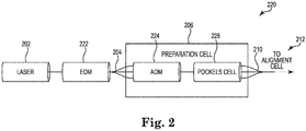
- Figure 2 illustrates an example of a preparation cell system 220 in accordance with one or more embodiments of the present disclosure.
- the preparation cell system 220 can be one example embodiment of a preparation cell system 100 as referenced in Figure 1 .
- the preparation cell system 220 can include a light source such as a laser 202.
- the system 220 can utilize a Doppler cooling (DC) laser 202.
- DC Doppler cooling
- the laser 202 can be coupled to an electro-optical modulator (EOM) 222.
- EOM electro-optical modulator
- the EOM 222 can be a 7.37 GHz EOM that is coupled between the laser 202 and a fiber bundle. That is, the EOM 222 can be utilized to prepare a state of the laser 202 prior to the light from the laser 202 being received at a fiber bundle (e.g., fiber bundle 104 as referenced in Figure 1 , not shown in Figure 2 ).
- a fiber bundle can receive light whose state has been prepared by the EOM 222 and split the light via a plurality of separated fibers (e.g., separated fibers 108-1 as referenced in Figure 1 , etc.).
- the plurality of separated fibers can be coupled to a preparation cell 206.
- the preparation cell can include a number of tracks comprising an AOM 224 and/or a Pockels cell 226.
- the preparation cell 206 can include an AOM 224 coupled to each of the separated fibers coupled to the preparation cell 206.
- the AOM 224 can be utilized to set a frequency of the received laser light and/or shutter the received laser light.
- the AOM 224 can be a 200 MHz AOM.
- a radio frequency switch (RF switch) and/or microwave switch can be utilized to control light leakage that can be caused by the AOM 224 shutter.
- RF switch radio frequency switch
- microwave switch can be utilized to control light leakage that can be caused by the AOM 224 shutter.
- the AOM 224 that is coupled to each of the plurality of separated fibers can be coupled to a Pockels cell 226.
- the Pockels cell 226 can be utilized to set a polarization of the laser light passing through the separated fibers.
- the plurality of fibers from the preparation cell can be coupled to an alignment cell 212 (e.g., alignment cell 112 as referenced in Figure 1 ) via a vacuum port fiber bundle 210 (e.g., vacuum port fiber bundle 110 as referenced in Figure 1 ).
- Figure 3 illustrates an example of a preparation cell system 330 in accordance with one or more embodiments of the present disclosure.
- the preparation cell system 330 can be one example embodiment of a preparation cell system 100 as referenced in Figure 1 .
- the preparation cell system 330 can include a light source such as a laser 302.
- the system 330 can include a quantum operation (QO) laser 302.
- QO quantum operation
- the laser 302 can be coupled to a fiber bundle (e.g., fiber bundle 104 as referenced in Figure 1 , not shown in Figure 3 ).
- the fiber bundle 304 can be utilized to receive light from the laser 302 and split the light from the laser 302 into a plurality of separated fibers.
- Each of the separated fibers can be coupled to the preparation cell 306.
- the preparation cell can include a number of tracks comprising an EOM 322, an AOM 324, and a Pockels cell 326 coupled to each separated fiber.
- Each of the separated fibers can be first coupled to an EOM 322 within the preparation cell 306.
- the EOM 322 can be utilized to prepare the state of the laser light of each of the separated fibers.
- the EOM coupled to each of the number of separated fibers can be a 2.1 GHz EOM.
- the preparation cell 306 can include an AOM 324 coupled to each of the separated fibers and corresponding EOM 322 coupled to the preparation cell 306.
- the AOM 324 can be utilized to set a frequency of the received laser light and/or shutter the received laser light.
- the AOM 324 can be a 200 MHz AOM.
- a radio frequency switch (RF switch) and/or microwave switch can be utilized to control light leakage that can be caused by the AOM 324 shutter.
- the AOM 324 that is coupled to each of the plurality of separated fibers can be coupled to a Pockels cell 326.
- the Pockels cell 326 can be utilized to set a polarization of the laser light passing through the separated fibers.
- the plurality of fibers from the preparation cell can be coupled to an alignment cell 312 (e.g., alignment cell 112 as referenced in Figure 1 ) via a vacuum port fiber bundle 310 (e.g., vacuum port fiber bundle 110 as referenced in Figure 1 ).
- the system 330 can be utilized to individually address a relatively large number of ions while minimizing a number of QO lasers that need to be utilized.
- the system 330 can utilize a preparation cell 306 to receive a number of separated fibers with light from an incident laser 302.
- the preparation cell 306 can simultaneously prepare a state of the received light from each of the separated fibers and provide the prepared light state to an alignment cell 312.
- the system 330 can be utilized to set and interrogate ytterbium's hyperfine states.
- a single laser can be utilized to act as a number of different light sources for the alignment cell 312 and minimize the number of lasers needed to simultaneously feed a plurality of ion traps with laser light.
Landscapes
- Physics & Mathematics (AREA)
- Nonlinear Science (AREA)
- General Physics & Mathematics (AREA)
- Optics & Photonics (AREA)
- Chemical & Material Sciences (AREA)
- Health & Medical Sciences (AREA)
- Analytical Chemistry (AREA)
- Engineering & Computer Science (AREA)
- Electromagnetism (AREA)
- Ceramic Engineering (AREA)
- Crystallography & Structural Chemistry (AREA)
- General Health & Medical Sciences (AREA)
- Nuclear Medicine, Radiotherapy & Molecular Imaging (AREA)
- Life Sciences & Earth Sciences (AREA)
- Biochemistry (AREA)
- Immunology (AREA)
- Pathology (AREA)
- Plasma & Fusion (AREA)
- Optical Modulation, Optical Deflection, Nonlinear Optics, Optical Demodulation, Optical Logic Elements (AREA)
- Lasers (AREA)
Abstract
Description
- This invention was made with Government support under contract: W911NF-12-1-0605, awarded by the U.S. Army. The Government has certain rights in this invention.
- The present disclosure relates to preparation cell systems and methods.
- Atom traps (e.g., ion traps, neutral atom traps, etc.) can be utilized to isolate atoms for experimentation. For example, ion traps can use a combination of electrical and magnetic fields to capture an ion in a potential well. In this example, when an ion trapped in an ion trap is illuminated by a specific laser (e.g. when a laser beam is shined on the ion in the trap), the ion may fluoresce light. The light fluoresced from the ion can be detected by a detector.
- Increasing the number of ion traps on a single die can be space limited due to on-chip filter capacitors and optically limited due to wire bonds in a beam path. In some previous approaches, a number of lasers may be linearly added when adding additional ions to address. Ion traps have a number of uses such as mass spectrometry, spectroscopy, basic physics research, and/or controlling quantum states.
-
-
Figure 1 illustrates an example of a preparation cell system in accordance with one or more embodiments of the present disclosure. -
Figure 2 illustrates an example of a preparation cell system in accordance with one or more embodiments of the present disclosure. -
Figure 3 illustrates an example of a preparation cell system in accordance with one or more embodiments of the present disclosure. - A number of preparation cell systems and methods are described herein. One example of a system for a preparation cell can include a laser coupled to a fiber bundle comprising a plurality of fibers, a preparation cell to prepare a state of laser light received by the fiber bundle, and an exiting fiber bundle coupled to a preparation cell. Another example of a system for a preparation cell can include a laser coupled to an electro-optical modulator (EOM), a fiber bundle comprising a plurality of fibers coupled to the EOM, a preparation cell to: set a frequency and polarization of laser light received by the plurality of fibers from the EOM and shutter the laser light received by the plurality of fibers from the EOM, and a vacuum port fiber bundle coupled to the alignment cell. Furthermore, an example a system for a preparation cell can include a laser coupled to a fiber bundle comprising a plurality of fibers, a preparation cell comprising a plurality of electro-optical modulators (EOMs), wherein each respective EOM is coupled to a different one of the plurality of fibers separated by the fiber bundle, and a vacuum port fiber bundle coupled to an alignment cell to receive the plurality of fibers.
- The preparation cell systems described herein can be utilized in a single-ion addressing system. For example, the preparation cell system can be coupled to an alignment cell inside a vacuum chamber, and/or a detection cell. The alignment cell can include a plurality of ion traps and/or ion trapping zones within a single trap. In some embodiments, the alignment cell can utilize the preparation cell systems to split a laser source into a plurality of fibers that can be utilized for a number of the plurality of ion traps or zones. For example, a single laser source can be split from a fiber bundle into a plurality of fibers, have a state prepared by a preparation cell, and the plurality of fibers can be received by a vacuum port fiber bundle coupled to the alignment cell. In previous approaches, a plurality of lasers could be needed to simultaneously hit a number of ions located at a plurality of ion traps. For example, a plurality of additional lasers could be needed for each number of ions to be added.
- In some embodiments, the laser may be a Doppler cooling laser (e.g., a laser used in a Doppler cooling mechanism), and in some embodiments the laser may be an operation laser (e.g., a laser used in Raman cooling, state preparation, EIT manipulation, and/or gate experiments, for instance). In both such embodiments, the laser may be a 369 nanometer (nm) laser. However, embodiments of the present disclosure are not limited to a particular type of laser.
- The preparation cell systems described herein can be utilized to generate relatively large spacing sidebands for state preparation and addressing hyperfine transitions utilizing an electro-optical modulator (EOM) that is coupled to a number of the plurality of fibers. In addition, the preparation cell systems described herein can be utilized to set a frequency of the laser light and/or shutter the laser light utilizing an acousto-optic modulator (AOM) that is coupled to a number of the plurality of fibers. Furthermore, the preparation cell systems described herein can be utilized to set a polarization state of the laser light utilizing, for example, a Pockels cell coupled to a number of the plurality of fibers. In some embodiments, a plurality of tracks can be used within the preparation cell. Each of the plurality of tracks can include one or more of an EOM, AOM, and/or Pockels cell to prepare a state of the received laser light as described herein. The light from the preparation cell system can be sent to an alignment cell via a vacuum port fiber bundle coupled to the alignment cell. Ion traps are discussed herein as specific examples. However, specific implementations are not limited to only ion traps. That is, the preparation cell systems and methods can be utilized in combination with a number of different atom trap types.
- In the following detailed description, reference is made to the accompanying drawings that form a part hereof. The drawings show by way of illustration how one or more embodiments of the disclosure may be practiced.
- These embodiments are described in sufficient detail to enable those of ordinary skill in the art to practice one or more embodiments of this disclosure. It is to be understood that other embodiments may be utilized and that mechanical, electrical, and/or process changes may be made without departing from the scope of the present disclosure.
- As will be appreciated, elements shown in the various embodiments herein can be added, exchanged, combined, and/or eliminated so as to provide a number of additional embodiments of the present disclosure. The proportion and the relative scale of the elements provided in the figures are intended to illustrate the embodiments of the present disclosure, and should not be taken in a limiting sense.
- The figures herein follow a numbering convention in which the first digit or digits correspond to the drawing figure number and the remaining digits identify an element or component in the drawing. Similar elements or components between different figures may be identified by the use of similar digits. For example, 104 may reference element "04" in
Figure 1 , and a similar element may be referenced as 304 inFigure 3 . - As used herein, "a" or "a number of" something can refer to one or more such things. For example, "a number of lasers" can refer to one or more lasers.
-
Figure 1 illustrates an example of apreparation cell system 100 in accordance with one or more embodiments of the present disclosure. Thepreparation cell system 100 can be utilized to prepare light from anincident laser 102 for utilization in analignment cell 112. - The
preparation cell system 100 can utilize afiber bundle 104 to receive light from theincident laser 102. Thefiber bundle 104 can be coupled to a plurality of tracks (e.g., multi-track, etc.) within a preparation cell 106 (e.g., fiber separator, fiber separator comprising an EOM, AOM, and/or Pockels Cell, etc.). In some embodiments, theincident laser 102 can be a collimated (e.g., accurately make rays of light or particles parallel) with a flat-top laser irradiance profile. In addition, theincident laser 102 can be the same diameter as thefiber bundle 104 to avoid light from theincident laser 102 from escaping an exterior portion of thefiber bundle 104. - The
preparation cell 106 can receive a number of separated fibers 108-1 from thefiber bundle 104 coupled to theincident laser 102. In some embodiments, an electro-optical modulator (EOM) can be coupled to theincident laser 102 and the EOM can be coupled to thefiber bundle 104. The EOM can be coupled to theincident laser 102 when theincident laser 102 is a Doppler cooling (DC) laser or similar light source. In some embodiments the EOM can be a 7.37 gigahertz (GHz) EOM that prepares the state of theincident laser 102 prior to entering thefiber bundle 104. In some embodiments, each separated fiber 108-1 can have the same and/or nearly the same irradiance. That is, the light from theincident laser 102 that is incident upon each fiber within thefiber bundle 104 can have the same irradiance transferred to each separated fiber 108-1 coupled to thepreparation cell 106. - In some embodiments, the
preparation cell 106 can include an EOM coupled to each of the number of separated fibers 108-1 instead of a single EOM coupled to theincident laser 102. In these embodiments, the EOM coupled to each of the number of separated fibers 108-1 can be utilized to prepare the state of the light from theincident laser 102 of each of the separated fibers 108-1. In these embodiments, the EOM coupled to each of the number of separated fibers 108-1 can be a 2.1 GHz EOM and theincident laser 102 can be a state preparation laser or similar light source. That is, thepreparation cell 106 can be used for laser cooling, state preparation, or a number of other processes that may require specifically prepared laser sources. - In some embodiments, the
preparation cell 106 can include an acousto-optic modulator (AOM) coupled to each of the separated fibers 108-1. The AOM can be utilized to shutter (e.g., alternate between allowing the light through and not allowing the light through the preparation cell 106) the laser light from each of the separated fibers 108-1. In some embodiments, the AOM can be utilized for signal modulation and frequency control of the laser light passing through the separated fibers 108-1. In some embodiments, a radio frequency switch (RF switch) and/or microwave switch can be utilized to control light leakage that can be caused by the AOM shutter. - In some embodiments, the
preparation cell 106 can include a device to set the beam polarization, such as a Pockels cell, that can be coupled to the AOM. The Pockels cell can include a voltage controlled wave plate (e.g., half-wave plate, quarter-wave plate, etc.). In some embodiments, the Pockels cell can be utilized to set a polarization of the laser light passing through the separated fibers 108-1 to a particular polarization (e.g., vertical, horizontal, combination, etc.). - The light from the
incident laser 102 can be coupled to the EOM 122 and/or thefiber bundle 104 to pass light through a plurality of separated fibers 108-1 into thepreparation cell 106 to prepare a state of the light from theincident laser 102. After exiting thepreparation cell 106, the separated fibers 108-2 can be coupled to a vacuumport fiber bundle 110 that is coupled to analignment cell 112. That is, the plurality of fibers coupled to thefiber bundle 104 are separated into separate fibers 108-1 before entering thepreparation cell 106 and the separated fibers 108-2 after thepreparation cell 106 are coupled to the vacuumport fiber bundle 110. Although the embodiment illustrated inFigure 1 includes four fibers, embodiments of the present disclosure are not limited to a particular number of fibers. - The vacuum
port fiber bundle 110 can maintain a vacuum within thealignment cell 112 while allowing the separated fibers 108-2 to be coupled to thealignment cell 112. Thealignment cell 112 can utilize each of the separated fibers 108-2 to focus the corresponding laser light from each of the separated fibers 108-2 on an ion trap to allow the laser light of a particular separated fiber 108-2 to illuminate a particular ion that is trapped in a particular ion trap within thealignment cell 112. Previous systems and methods could require an additional number of lasers for each additional ion trap. In contrast, thesystem 100 can simultaneously utilize asingle incident laser 102 to focus laser light onto a plurality of different ion traps simultaneously. In addition, the light of each separated fiber 108-2 can have a particular state that was prepared by thepreparation cell 106. - When an ion within an ion trap is illuminated by the laser light from the light provided by the separated fibers 108-2 the ion can fluoresce light that can be captured by a number of fibers within the
alignment cell 112 that are coupled to the vacuumport fiber bundle 110. The fluoresced light from the number of ions in the ion traps can be received at adetection cell 114 via a number of fibers 108-3. In some embodiments, thedetection cell 114 can be outside the vacuum of thealignment cell 112 to reduce a quantity of space that is under vacuum. Thedetection cell 114 can be utilized to receive and quantify a time and brightness of the fluoresced light from the number of ions in the ion trap. - The
system 100 can be utilized to prepare light from anincident laser 102 utilizing a plurality of tracks (e.g., EOM, AOM, Pockels cell, etc.) within thepreparation cell 106 to address a plurality of ions. The quantity of ions that a single laser can address utilizing thesystem 100 can be determined by a number of factors. The number of factors can include, but is not limited to: a power of the illuminating laser, the power required at the ion, and/or a loss due to the components within the system (e.g.,preparation cell 106,alignment cell 112,detection cell 114, EOM, AOM, Pockels cell, etc.). In some embodiments, thepreparation cell 106 can be a main cause of light loss. - The
system 100 can be utilized to individually address a relatively large number of ions while minimizing the number of lasers that need to be utilized. Thesystem 100 can utilize apreparation cell 106 to receive a number of separated fibers 108-1 with light from anincident laser 102. The plurality of separated fibers 108-1 can be coupled to thepreparation cell 106 via a number of tracks. Thepreparation cell 106 can simultaneously prepare a state (e.g., frequency, shuttering, etc.) of the received light from each of the separated fibers 108-1 and provide the prepared light state to analignment cell 112. That is, thepreparation cell 106 can allow control over each of the separated fibers 108-1 prior to entering thealignment cell 112. Thus, a single laser can be utilized to act as a number of different light sources for thealignment cell 112 and minimize the number of lasers needed to simultaneously feed a plurality of ion traps with laser light. -
Figure 2 illustrates an example of apreparation cell system 220 in accordance with one or more embodiments of the present disclosure. Thepreparation cell system 220 can be one example embodiment of apreparation cell system 100 as referenced inFigure 1 . Thepreparation cell system 220 can include a light source such as alaser 202. In some embodiments, thesystem 220 can utilize a Doppler cooling (DC)laser 202. - The
laser 202 can be coupled to an electro-optical modulator (EOM) 222. In some embodiments, theEOM 222 can be a 7.37 GHz EOM that is coupled between thelaser 202 and a fiber bundle. That is, theEOM 222 can be utilized to prepare a state of thelaser 202 prior to the light from thelaser 202 being received at a fiber bundle (e.g.,fiber bundle 104 as referenced inFigure 1 , not shown inFigure 2 ). A fiber bundle can receive light whose state has been prepared by theEOM 222 and split the light via a plurality of separated fibers (e.g., separated fibers 108-1 as referenced inFigure 1 , etc.). - The plurality of separated fibers can be coupled to a
preparation cell 206. The preparation cell can include a number of tracks comprising anAOM 224 and/or aPockels cell 226. For example, thepreparation cell 206 can include anAOM 224 coupled to each of the separated fibers coupled to thepreparation cell 206. In some embodiments, theAOM 224 can be utilized to set a frequency of the received laser light and/or shutter the received laser light. In some embodiments, theAOM 224 can be a 200 MHz AOM. In some embodiments, a radio frequency switch (RF switch) and/or microwave switch can be utilized to control light leakage that can be caused by theAOM 224 shutter. - The
AOM 224 that is coupled to each of the plurality of separated fibers can be coupled to aPockels cell 226. As described herein, thePockels cell 226 can be utilized to set a polarization of the laser light passing through the separated fibers. The plurality of fibers from the preparation cell can be coupled to an alignment cell 212 (e.g.,alignment cell 112 as referenced inFigure 1 ) via a vacuum port fiber bundle 210 (e.g., vacuumport fiber bundle 110 as referenced inFigure 1 ). -
Figure 3 illustrates an example of apreparation cell system 330 in accordance with one or more embodiments of the present disclosure. Thepreparation cell system 330 can be one example embodiment of apreparation cell system 100 as referenced inFigure 1 . Thepreparation cell system 330 can include a light source such as alaser 302. In some embodiments, thesystem 330 can include a quantum operation (QO)laser 302. - The
laser 302 can be coupled to a fiber bundle (e.g.,fiber bundle 104 as referenced inFigure 1 , not shown inFigure 3 ). Thefiber bundle 304 can be utilized to receive light from thelaser 302 and split the light from thelaser 302 into a plurality of separated fibers. Each of the separated fibers can be coupled to thepreparation cell 306. The preparation cell can include a number of tracks comprising anEOM 322, anAOM 324, and aPockels cell 326 coupled to each separated fiber. - Each of the separated fibers can be first coupled to an
EOM 322 within thepreparation cell 306. TheEOM 322 can be utilized to prepare the state of the laser light of each of the separated fibers. The EOM coupled to each of the number of separated fibers can be a 2.1 GHz EOM. - The
preparation cell 306 can include anAOM 324 coupled to each of the separated fibers andcorresponding EOM 322 coupled to thepreparation cell 306. In some embodiments, theAOM 324 can be utilized to set a frequency of the received laser light and/or shutter the received laser light. In some embodiments, theAOM 324 can be a 200 MHz AOM. In some embodiments, a radio frequency switch (RF switch) and/or microwave switch can be utilized to control light leakage that can be caused by theAOM 324 shutter. - The
AOM 324 that is coupled to each of the plurality of separated fibers can be coupled to aPockels cell 326. As described herein, thePockels cell 326 can be utilized to set a polarization of the laser light passing through the separated fibers. The plurality of fibers from the preparation cell can be coupled to an alignment cell 312 (e.g.,alignment cell 112 as referenced inFigure 1 ) via a vacuum port fiber bundle 310 (e.g., vacuumport fiber bundle 110 as referenced inFigure 1 ). - The
system 330 can be utilized to individually address a relatively large number of ions while minimizing a number of QO lasers that need to be utilized. Thesystem 330 can utilize apreparation cell 306 to receive a number of separated fibers with light from anincident laser 302. Thepreparation cell 306 can simultaneously prepare a state of the received light from each of the separated fibers and provide the prepared light state to analignment cell 312. In some embodiments, thesystem 330 can be utilized to set and interrogate ytterbium's hyperfine states. Thus, a single laser can be utilized to act as a number of different light sources for thealignment cell 312 and minimize the number of lasers needed to simultaneously feed a plurality of ion traps with laser light. - Although specific embodiments have been illustrated and described herein, those of ordinary skill in the art will appreciate that any arrangement calculated to achieve the same techniques can be substituted for the specific embodiments shown. This disclosure is intended to cover any and all adaptations or variations of various embodiments of the disclosure.
- It is to be understood that the above description has been made in an illustrative fashion, and not a restrictive one. Combination of the above embodiments, and other embodiments not specifically described herein will be apparent to those of skill in the art upon reviewing the above description.
- The scope of the various embodiments of the disclosure includes any other applications in which the above elements and methods are used. Therefore, the scope of various embodiments of the disclosure should be determined with reference to the appended claims, along with the full range of equivalents to which such claims are entitled.
- In the foregoing Detailed Description, various features are grouped together in example embodiments illustrated in the figures for the purpose of streamlining the disclosure. This method of disclosure is not to be interpreted as reflecting an intention that the embodiments of the disclosure require more features than are expressly recited in each claim.
- Rather, as the following claims reflect, inventive subject matter lies in less than all features of a single disclosed embodiment. Thus, the following claims are hereby incorporated into the Detailed Description, with each claim standing on its own as a separate embodiment.
Claims (15)
- A preparation cell system, comprising:a laser(102) coupled to a fiber bundle(104) comprising a plurality of fibers(108);a preparation cell(106) to prepare a state of laser light received by the fiber bundle(104); andanexiting fiber bundle(110) coupled to the preparation cell(106).
- The system of claim 1, comprising an elctro-optical modulator (EOM) coupled to the laser(102), wherein the fiber bundle(104) is coupled to the EOM.
- The system of claim 2, comprising an acousto-optical modulator (AOM) coupled to the fiber bundle(104).
- The system of claim 3, comprising a Pockels cell coupled to the AOM, wherein the Pockels cell is coupled to the exiting fiber bundle(110).
- The system of claim 1, comprising an elctro-optical modulator (EOM) coupled to the fiber bundle(104).
- The system of claim 5, comprising an AOM coupled to the EOM.
- The system of claim 6, comprising a Pockels cell coupled to the AOM, wherein the pockels cell is coupled to the exiting fiber bundle(110).
- The system of claim 6, wherein the EOM generates spacing sidebands for each of the plurality of fibers(108).
- The system of claim 1, comprising an RF switch coupled to the plurality of AOMs to control light leakage from an AOM shutter.
- The system of claim 1, wherein the laser(102) is a cooling laser.
- The system of claim 10, wherein the cooling laser is a Doppler cooling (DC) laser.
- The system of claim 1,wherein the EOM generates spacing sidebands for each of the plurality of fibers (108).
- The system of claim 1, comprising a plurality of AOMs, wherein each respective AOM is coupled to a different one of a plurality of EOMs.
- The system of claim 13, comprising a plurality of Pockels cells, wherein each respective Pockels cell is coupled to a different one of the plurality of AOMs.
- The system of claim 1, wherein light received by each of the plurality of fibers (108) from the laser (102) is individually shuttered and prepared prior to entering a vacuum port fiber bundle.
Applications Claiming Priority (1)
| Application Number | Priority Date | Filing Date | Title |
|---|---|---|---|
| US14/686,481 US9645417B2 (en) | 2015-04-14 | 2015-04-14 | Preparation cell systems and methods of a preparing a state of laser light |
Publications (3)
| Publication Number | Publication Date |
|---|---|
| EP3081924A1 true EP3081924A1 (en) | 2016-10-19 |
| EP3081924B1 EP3081924B1 (en) | 2024-06-12 |
| EP3081924C0 EP3081924C0 (en) | 2024-06-12 |
Family
ID=55349676
Family Applications (1)
| Application Number | Title | Priority Date | Filing Date |
|---|---|---|---|
| EP16154710.4A Active EP3081924B1 (en) | 2015-04-14 | 2016-02-08 | Ion trap with optical preparation cell |
Country Status (2)
| Country | Link |
|---|---|
| US (2) | US9645417B2 (en) |
| EP (1) | EP3081924B1 (en) |
Families Citing this family (3)
| Publication number | Priority date | Publication date | Assignee | Title |
|---|---|---|---|---|
| US11042052B2 (en) * | 2018-09-18 | 2021-06-22 | Eagle Technology, Llc | Multi-channel laser system including an acousto-optic modulator (AOM) with beam polarization switching and related methods |
| US11327348B2 (en) | 2018-09-18 | 2022-05-10 | Eagle Technology, Llc | Multi-channel laser system including optical assembly with etched optical signal channels and related methods |
| EP4657148A1 (en) * | 2024-05-30 | 2025-12-03 | Pasqal | A device for modulating a laser beam in a quantum system |
Citations (1)
| Publication number | Priority date | Publication date | Assignee | Title |
|---|---|---|---|---|
| US20020168134A1 (en) * | 2001-05-11 | 2002-11-14 | Mani Sundaram | Laser beam steering system |
Family Cites Families (7)
| Publication number | Priority date | Publication date | Assignee | Title |
|---|---|---|---|---|
| US6613588B2 (en) * | 1999-03-02 | 2003-09-02 | Hitachi, Ltd. | Floating particle inspection method and its apparatus and a semiconductor device processing apparatus |
| US20060249491A1 (en) * | 1999-09-01 | 2006-11-09 | Hell Gravure Systems Gmbh | Laser radiation source |
| US7518120B2 (en) * | 2005-01-04 | 2009-04-14 | The Regents Of The University Of Michigan | Long-distance quantum communication and scalable quantum computation |
| US7180078B2 (en) * | 2005-02-01 | 2007-02-20 | Lucent Technologies Inc. | Integrated planar ion traps |
| JP5622571B2 (en) * | 2007-07-20 | 2014-11-12 | メディツィーニシェ・ウニヴェルジテート・インスブルックMedizinische Universitaet Innsbruck | Optical device comprising a pair of diffractive optical elements |
| US7580609B1 (en) * | 2008-06-20 | 2009-08-25 | Gooch & Housego Plc | Fiber intensity reducing devices and related systems |
| US8309885B2 (en) * | 2009-01-15 | 2012-11-13 | Electro Scientific Industries, Inc. | Pulse temporal programmable ultrafast burst mode laser for micromachining |
-
2015
- 2015-04-14 US US14/686,481 patent/US9645417B2/en active Active
-
2016
- 2016-02-08 EP EP16154710.4A patent/EP3081924B1/en active Active
-
2017
- 2017-05-02 US US15/584,456 patent/US10302974B2/en active Active
Patent Citations (1)
| Publication number | Priority date | Publication date | Assignee | Title |
|---|---|---|---|---|
| US20020168134A1 (en) * | 2001-05-11 | 2002-11-14 | Mani Sundaram | Laser beam steering system |
Non-Patent Citations (2)
| Title |
|---|
| H C NÄ ET AL: "Laser addressing of individual ions in a linear ion trap", 10 December 1998 (1998-12-10), XP055297099, Retrieved from the Internet <URL:http://www.quantumoptics.at/images/publications/papers/pra99_adressing.pdf> [retrieved on 20160824] * |
| JUNGSANG KIM ET AL: "Integrated Optical Approach to Trapped Ion Quantum Computation", ARXIV.ORG, CORNELL UNIVERSITY LIBRARY, 201 OLIN LIBRARY CORNELL UNIVERSITY ITHACA, NY 14853, 25 November 2007 (2007-11-25), XP080340796 * |
Also Published As
| Publication number | Publication date |
|---|---|
| US20160306200A1 (en) | 2016-10-20 |
| US9645417B2 (en) | 2017-05-09 |
| US10302974B2 (en) | 2019-05-28 |
| US20170235163A1 (en) | 2017-08-17 |
| EP3081924B1 (en) | 2024-06-12 |
| EP3081924C0 (en) | 2024-06-12 |
Similar Documents
| Publication | Publication Date | Title |
|---|---|---|
| US10145792B2 (en) | Multi-cell apparatus and method for single ion addressing | |
| Filsinger et al. | State-and conformer-selected beams of aligned and oriented molecules for ultrafast diffraction studies | |
| US10302974B2 (en) | Preparation cell systems and methods of preparing a state of laser light | |
| US9715950B2 (en) | Single cell apparatus and method for single ion addressing | |
| US20170018415A1 (en) | Divided-aperture laser differential confocal libs and raman spectrum-mass spectrum microscopic imaging method and device | |
| Lassen et al. | Current developments with TRIUMF’s titanium-sapphire laser based resonance ionization laser ion source: an overview | |
| Rouzée et al. | Photoelectron kinetic and angular distributions for the ionization of aligned molecules using a HHG source | |
| Yang et al. | Laser–radio-frequency double-resonance spectroscopy of 84− 87 Rb isotopes trapped in superfluid helium | |
| Tagliamonti et al. | Nonadiabatic dynamics and multiphoton resonances in strong-field molecular ionization with few-cycle laser pulses | |
| Studer et al. | Resonance ionization spectroscopy in dysprosium: Excitation scheme development and re-determination of the first ionization potential | |
| Hemmerling et al. | A single laser system for ground-state cooling of 25Mg+ | |
| Lassen et al. | Developments at TRIUMF’s laser resonance ionization ion source & multi-element operation | |
| CN104880418A (en) | Spectrum detecting system | |
| Kerbstadt et al. | Carrier-envelope-phase control of asymmetries in the multiphoton ionization of xenon atoms by ultrashort bichromatic fields | |
| Maksimchuk et al. | The ZEUS multi-petawatt laser system | |
| Jung et al. | All-diode-laser cooling of Sr+ isotope ions for analytical applications | |
| Veltcheva et al. | Brunel-dominated proton acceleration with a few-cycle laser pulse | |
| US20150292869A1 (en) | Organic Laser for Measurement | |
| DE102008048085A1 (en) | Differentiation of enantiomers using broadband femtosecond circular dichroism mass spectrometry | |
| Allcock | Surface-electrode ion traps for scalable quantum computing | |
| Beier et al. | Relativistic short-pulse high harmonic generation at 1.3 and 2.1 μ m wavelengths | |
| Huppert | Actively-stabilized attosecond beamline and its application to attosecond dynamics in atoms, molecules, and liquids | |
| Natan et al. | Angle Resolved Photoelectron Phase Shifts in Above Threshold Ionization | |
| Gatto | Trapping fermionic potassium atoms in a quasi-electrostatic optical dipole potential | |
| Sinyakova et al. | Pico–femto–attosecond metrology for advanced and XUV photon sources |
Legal Events
| Date | Code | Title | Description |
|---|---|---|---|
| PUAI | Public reference made under article 153(3) epc to a published international application that has entered the european phase |
Free format text: ORIGINAL CODE: 0009012 |
|
| 17P | Request for examination filed |
Effective date: 20160208 |
|
| AK | Designated contracting states |
Kind code of ref document: A1 Designated state(s): AL AT BE BG CH CY CZ DE DK EE ES FI FR GB GR HR HU IE IS IT LI LT LU LV MC MK MT NL NO PL PT RO RS SE SI SK SM TR |
|
| AX | Request for extension of the european patent |
Extension state: BA ME |
|
| STAA | Information on the status of an ep patent application or granted ep patent |
Free format text: STATUS: EXAMINATION IS IN PROGRESS |
|
| 17Q | First examination report despatched |
Effective date: 20191126 |
|
| P01 | Opt-out of the competence of the unified patent court (upc) registered |
Effective date: 20230526 |
|
| REG | Reference to a national code |
Ref country code: DE Ref legal event code: R079 Free format text: PREVIOUS MAIN CLASS: G01N0021640000 Ipc: G02F0001125000 Ref country code: DE Ref legal event code: R079 Ref document number: 602016087921 Country of ref document: DE Free format text: PREVIOUS MAIN CLASS: G01N0021640000 Ipc: G02F0001125000 |
|
| RIC1 | Information provided on ipc code assigned before grant |
Ipc: G01N 21/64 20060101ALI20231206BHEP Ipc: H01J 49/42 20060101ALI20231206BHEP Ipc: H01J 49/00 20060101ALI20231206BHEP Ipc: G02F 1/11 20060101ALI20231206BHEP Ipc: G02F 1/035 20060101ALI20231206BHEP Ipc: G02F 1/01 20060101ALI20231206BHEP Ipc: G02F 1/125 20060101AFI20231206BHEP |
|
| GRAP | Despatch of communication of intention to grant a patent |
Free format text: ORIGINAL CODE: EPIDOSNIGR1 |
|
| STAA | Information on the status of an ep patent application or granted ep patent |
Free format text: STATUS: GRANT OF PATENT IS INTENDED |
|
| INTG | Intention to grant announced |
Effective date: 20240117 |
|
| RAP1 | Party data changed (applicant data changed or rights of an application transferred) |
Owner name: QUANTINUUM LLC |
|
| GRAS | Grant fee paid |
Free format text: ORIGINAL CODE: EPIDOSNIGR3 |
|
| GRAA | (expected) grant |
Free format text: ORIGINAL CODE: 0009210 |
|
| STAA | Information on the status of an ep patent application or granted ep patent |
Free format text: STATUS: THE PATENT HAS BEEN GRANTED |
|
| AK | Designated contracting states |
Kind code of ref document: B1 Designated state(s): AL AT BE BG CH CY CZ DE DK EE ES FI FR GB GR HR HU IE IS IT LI LT LU LV MC MK MT NL NO PL PT RO RS SE SI SK SM TR |
|
| REG | Reference to a national code |
Ref country code: GB Ref legal event code: FG4D |
|
| REG | Reference to a national code |
Ref country code: CH Ref legal event code: EP |
|
| REG | Reference to a national code |
Ref country code: DE Ref legal event code: R096 Ref document number: 602016087921 Country of ref document: DE |
|
| REG | Reference to a national code |
Ref country code: IE Ref legal event code: FG4D |
|
| U01 | Request for unitary effect filed |
Effective date: 20240708 |
|
| U07 | Unitary effect registered |
Designated state(s): AT BE BG DE DK EE FI FR IT LT LU LV MT NL PT SE SI Effective date: 20240716 |
|
| P04 | Withdrawal of opt-out of the competence of the unified patent court (upc) registered |
Free format text: CASE NUMBER: APP_41240/2024 Effective date: 20240712 |
|
| PG25 | Lapsed in a contracting state [announced via postgrant information from national office to epo] |
Ref country code: HR Free format text: LAPSE BECAUSE OF FAILURE TO SUBMIT A TRANSLATION OF THE DESCRIPTION OR TO PAY THE FEE WITHIN THE PRESCRIBED TIME-LIMIT Effective date: 20240612 |
|
| PG25 | Lapsed in a contracting state [announced via postgrant information from national office to epo] |
Ref country code: GR Free format text: LAPSE BECAUSE OF FAILURE TO SUBMIT A TRANSLATION OF THE DESCRIPTION OR TO PAY THE FEE WITHIN THE PRESCRIBED TIME-LIMIT Effective date: 20240913 |
|
| PG25 | Lapsed in a contracting state [announced via postgrant information from national office to epo] |
Ref country code: ES Free format text: LAPSE BECAUSE OF FAILURE TO SUBMIT A TRANSLATION OF THE DESCRIPTION OR TO PAY THE FEE WITHIN THE PRESCRIBED TIME-LIMIT Effective date: 20240612 |
|
| PG25 | Lapsed in a contracting state [announced via postgrant information from national office to epo] |
Ref country code: NO Free format text: LAPSE BECAUSE OF FAILURE TO SUBMIT A TRANSLATION OF THE DESCRIPTION OR TO PAY THE FEE WITHIN THE PRESCRIBED TIME-LIMIT Effective date: 20240912 Ref country code: HR Free format text: LAPSE BECAUSE OF FAILURE TO SUBMIT A TRANSLATION OF THE DESCRIPTION OR TO PAY THE FEE WITHIN THE PRESCRIBED TIME-LIMIT Effective date: 20240612 Ref country code: GR Free format text: LAPSE BECAUSE OF FAILURE TO SUBMIT A TRANSLATION OF THE DESCRIPTION OR TO PAY THE FEE WITHIN THE PRESCRIBED TIME-LIMIT Effective date: 20240913 Ref country code: ES Free format text: LAPSE BECAUSE OF FAILURE TO SUBMIT A TRANSLATION OF THE DESCRIPTION OR TO PAY THE FEE WITHIN THE PRESCRIBED TIME-LIMIT Effective date: 20240612 Ref country code: RS Free format text: LAPSE BECAUSE OF FAILURE TO SUBMIT A TRANSLATION OF THE DESCRIPTION OR TO PAY THE FEE WITHIN THE PRESCRIBED TIME-LIMIT Effective date: 20240912 |
|
| P05 | Withdrawal of opt-out of the competence of the unified patent court (upc) changed |
Free format text: CASE NUMBER: APP_41240/2024 Effective date: 20240716 |
|
| PG25 | Lapsed in a contracting state [announced via postgrant information from national office to epo] |
Ref country code: PL Free format text: LAPSE BECAUSE OF FAILURE TO SUBMIT A TRANSLATION OF THE DESCRIPTION OR TO PAY THE FEE WITHIN THE PRESCRIBED TIME-LIMIT Effective date: 20240612 |
|
| PG25 | Lapsed in a contracting state [announced via postgrant information from national office to epo] |
Ref country code: IS Free format text: LAPSE BECAUSE OF FAILURE TO SUBMIT A TRANSLATION OF THE DESCRIPTION OR TO PAY THE FEE WITHIN THE PRESCRIBED TIME-LIMIT Effective date: 20241012 |
|
| PG25 | Lapsed in a contracting state [announced via postgrant information from national office to epo] |
Ref country code: CZ Free format text: LAPSE BECAUSE OF FAILURE TO SUBMIT A TRANSLATION OF THE DESCRIPTION OR TO PAY THE FEE WITHIN THE PRESCRIBED TIME-LIMIT Effective date: 20240612 |
|
| PG25 | Lapsed in a contracting state [announced via postgrant information from national office to epo] |
Ref country code: RO Free format text: LAPSE BECAUSE OF FAILURE TO SUBMIT A TRANSLATION OF THE DESCRIPTION OR TO PAY THE FEE WITHIN THE PRESCRIBED TIME-LIMIT Effective date: 20240612 Ref country code: SK Free format text: LAPSE BECAUSE OF FAILURE TO SUBMIT A TRANSLATION OF THE DESCRIPTION OR TO PAY THE FEE WITHIN THE PRESCRIBED TIME-LIMIT Effective date: 20240612 |
|
| PG25 | Lapsed in a contracting state [announced via postgrant information from national office to epo] |
Ref country code: SM Free format text: LAPSE BECAUSE OF FAILURE TO SUBMIT A TRANSLATION OF THE DESCRIPTION OR TO PAY THE FEE WITHIN THE PRESCRIBED TIME-LIMIT Effective date: 20240612 |
|
| PG25 | Lapsed in a contracting state [announced via postgrant information from national office to epo] |
Ref country code: SM Free format text: LAPSE BECAUSE OF FAILURE TO SUBMIT A TRANSLATION OF THE DESCRIPTION OR TO PAY THE FEE WITHIN THE PRESCRIBED TIME-LIMIT Effective date: 20240612 Ref country code: SK Free format text: LAPSE BECAUSE OF FAILURE TO SUBMIT A TRANSLATION OF THE DESCRIPTION OR TO PAY THE FEE WITHIN THE PRESCRIBED TIME-LIMIT Effective date: 20240612 Ref country code: RO Free format text: LAPSE BECAUSE OF FAILURE TO SUBMIT A TRANSLATION OF THE DESCRIPTION OR TO PAY THE FEE WITHIN THE PRESCRIBED TIME-LIMIT Effective date: 20240612 Ref country code: PL Free format text: LAPSE BECAUSE OF FAILURE TO SUBMIT A TRANSLATION OF THE DESCRIPTION OR TO PAY THE FEE WITHIN THE PRESCRIBED TIME-LIMIT Effective date: 20240612 Ref country code: IS Free format text: LAPSE BECAUSE OF FAILURE TO SUBMIT A TRANSLATION OF THE DESCRIPTION OR TO PAY THE FEE WITHIN THE PRESCRIBED TIME-LIMIT Effective date: 20241012 Ref country code: CZ Free format text: LAPSE BECAUSE OF FAILURE TO SUBMIT A TRANSLATION OF THE DESCRIPTION OR TO PAY THE FEE WITHIN THE PRESCRIBED TIME-LIMIT Effective date: 20240612 |
|
| PLBE | No opposition filed within time limit |
Free format text: ORIGINAL CODE: 0009261 |
|
| STAA | Information on the status of an ep patent application or granted ep patent |
Free format text: STATUS: NO OPPOSITION FILED WITHIN TIME LIMIT |
|
| 26N | No opposition filed |
Effective date: 20250313 |
|
| U21 | Renewal fee for the european patent with unitary effect paid with additional fee |
Year of fee payment: 10 Effective date: 20250428 |
|
| PG25 | Lapsed in a contracting state [announced via postgrant information from national office to epo] |
Ref country code: MC Free format text: LAPSE BECAUSE OF FAILURE TO SUBMIT A TRANSLATION OF THE DESCRIPTION OR TO PAY THE FEE WITHIN THE PRESCRIBED TIME-LIMIT Effective date: 20240612 |
|
| PG25 | Lapsed in a contracting state [announced via postgrant information from national office to epo] |
Ref country code: IE Free format text: LAPSE BECAUSE OF NON-PAYMENT OF DUE FEES Effective date: 20250208 |
|
| REG | Reference to a national code |
Ref country code: CH Ref legal event code: U11 Free format text: ST27 STATUS EVENT CODE: U-0-0-U10-U11 (AS PROVIDED BY THE NATIONAL OFFICE) Effective date: 20260301 |
|
| U20 | Renewal fee for the european patent with unitary effect paid |
Year of fee payment: 11 Effective date: 20260227 |
|
| PGFP | Annual fee paid to national office [announced via postgrant information from national office to epo] |
Ref country code: GB Payment date: 20260227 Year of fee payment: 11 |
|
| PGFP | Annual fee paid to national office [announced via postgrant information from national office to epo] |
Ref country code: CH Payment date: 20260301 Year of fee payment: 11 |