EP3081871A1 - Dehumidifier - Google Patents
Dehumidifier Download PDFInfo
- Publication number
- EP3081871A1 EP3081871A1 EP16164864.7A EP16164864A EP3081871A1 EP 3081871 A1 EP3081871 A1 EP 3081871A1 EP 16164864 A EP16164864 A EP 16164864A EP 3081871 A1 EP3081871 A1 EP 3081871A1
- Authority
- EP
- European Patent Office
- Prior art keywords
- row
- tubes
- fin
- dehumidifier
- fixing part
- Prior art date
- Legal status (The legal status is an assumption and is not a legal conclusion. Google has not performed a legal analysis and makes no representation as to the accuracy of the status listed.)
- Granted
Links
Images


Classifications
-
- F—MECHANICAL ENGINEERING; LIGHTING; HEATING; WEAPONS; BLASTING
- F24—HEATING; RANGES; VENTILATING
- F24F—AIR-CONDITIONING; AIR-HUMIDIFICATION; VENTILATION; USE OF AIR CURRENTS FOR SCREENING
- F24F3/00—Air-conditioning systems in which conditioned primary air is supplied from one or more central stations to distributing units in the rooms or spaces where it may receive secondary treatment; Apparatus specially designed for such systems
- F24F3/12—Air-conditioning systems in which conditioned primary air is supplied from one or more central stations to distributing units in the rooms or spaces where it may receive secondary treatment; Apparatus specially designed for such systems characterised by the treatment of the air otherwise than by heating and cooling
- F24F3/14—Air-conditioning systems in which conditioned primary air is supplied from one or more central stations to distributing units in the rooms or spaces where it may receive secondary treatment; Apparatus specially designed for such systems characterised by the treatment of the air otherwise than by heating and cooling by humidification; by dehumidification
- F24F3/1405—Air-conditioning systems in which conditioned primary air is supplied from one or more central stations to distributing units in the rooms or spaces where it may receive secondary treatment; Apparatus specially designed for such systems characterised by the treatment of the air otherwise than by heating and cooling by humidification; by dehumidification in which the humidity of the air is exclusively affected by contact with the evaporator of a closed-circuit cooling system or heat pump circuit
-
- F—MECHANICAL ENGINEERING; LIGHTING; HEATING; WEAPONS; BLASTING
- F25—REFRIGERATION OR COOLING; COMBINED HEATING AND REFRIGERATION SYSTEMS; HEAT PUMP SYSTEMS; MANUFACTURE OR STORAGE OF ICE; LIQUEFACTION SOLIDIFICATION OF GASES
- F25B—REFRIGERATION MACHINES, PLANTS OR SYSTEMS; COMBINED HEATING AND REFRIGERATION SYSTEMS; HEAT PUMP SYSTEMS
- F25B39/00—Evaporators; Condensers
- F25B39/04—Condensers
-
- F—MECHANICAL ENGINEERING; LIGHTING; HEATING; WEAPONS; BLASTING
- F28—HEAT EXCHANGE IN GENERAL
- F28F—DETAILS OF HEAT-EXCHANGE AND HEAT-TRANSFER APPARATUS, OF GENERAL APPLICATION
- F28F1/00—Tubular elements; Assemblies of tubular elements
- F28F1/10—Tubular elements and assemblies thereof with means for increasing heat-transfer area, e.g. with fins, with projections, with recesses
- F28F1/12—Tubular elements and assemblies thereof with means for increasing heat-transfer area, e.g. with fins, with projections, with recesses the means being only outside the tubular element
- F28F1/24—Tubular elements and assemblies thereof with means for increasing heat-transfer area, e.g. with fins, with projections, with recesses the means being only outside the tubular element and extending transversely
- F28F1/32—Tubular elements and assemblies thereof with means for increasing heat-transfer area, e.g. with fins, with projections, with recesses the means being only outside the tubular element and extending transversely the means having portions engaging further tubular elements
-
- F—MECHANICAL ENGINEERING; LIGHTING; HEATING; WEAPONS; BLASTING
- F24—HEATING; RANGES; VENTILATING
- F24F—AIR-CONDITIONING; AIR-HUMIDIFICATION; VENTILATION; USE OF AIR CURRENTS FOR SCREENING
- F24F3/00—Air-conditioning systems in which conditioned primary air is supplied from one or more central stations to distributing units in the rooms or spaces where it may receive secondary treatment; Apparatus specially designed for such systems
- F24F3/12—Air-conditioning systems in which conditioned primary air is supplied from one or more central stations to distributing units in the rooms or spaces where it may receive secondary treatment; Apparatus specially designed for such systems characterised by the treatment of the air otherwise than by heating and cooling
- F24F3/14—Air-conditioning systems in which conditioned primary air is supplied from one or more central stations to distributing units in the rooms or spaces where it may receive secondary treatment; Apparatus specially designed for such systems characterised by the treatment of the air otherwise than by heating and cooling by humidification; by dehumidification
- F24F2003/144—Air-conditioning systems in which conditioned primary air is supplied from one or more central stations to distributing units in the rooms or spaces where it may receive secondary treatment; Apparatus specially designed for such systems characterised by the treatment of the air otherwise than by heating and cooling by humidification; by dehumidification by dehumidification only
- F24F2003/1446—Air-conditioning systems in which conditioned primary air is supplied from one or more central stations to distributing units in the rooms or spaces where it may receive secondary treatment; Apparatus specially designed for such systems characterised by the treatment of the air otherwise than by heating and cooling by humidification; by dehumidification by dehumidification only by condensing
-
- F—MECHANICAL ENGINEERING; LIGHTING; HEATING; WEAPONS; BLASTING
- F28—HEAT EXCHANGE IN GENERAL
- F28D—HEAT-EXCHANGE APPARATUS, NOT PROVIDED FOR IN ANOTHER SUBCLASS, IN WHICH THE HEAT-EXCHANGE MEDIA DO NOT COME INTO DIRECT CONTACT
- F28D1/00—Heat-exchange apparatus having stationary conduit assemblies for one heat-exchange medium only, the media being in contact with different sides of the conduit wall, in which the other heat-exchange medium is a large body of fluid, e.g. domestic or motor car radiators
- F28D1/02—Heat-exchange apparatus having stationary conduit assemblies for one heat-exchange medium only, the media being in contact with different sides of the conduit wall, in which the other heat-exchange medium is a large body of fluid, e.g. domestic or motor car radiators with heat-exchange conduits immersed in the body of fluid
- F28D1/04—Heat-exchange apparatus having stationary conduit assemblies for one heat-exchange medium only, the media being in contact with different sides of the conduit wall, in which the other heat-exchange medium is a large body of fluid, e.g. domestic or motor car radiators with heat-exchange conduits immersed in the body of fluid with tubular conduits
- F28D1/047—Heat-exchange apparatus having stationary conduit assemblies for one heat-exchange medium only, the media being in contact with different sides of the conduit wall, in which the other heat-exchange medium is a large body of fluid, e.g. domestic or motor car radiators with heat-exchange conduits immersed in the body of fluid with tubular conduits the conduits being bent, e.g. in a serpentine or zig-zag
- F28D1/0477—Heat-exchange apparatus having stationary conduit assemblies for one heat-exchange medium only, the media being in contact with different sides of the conduit wall, in which the other heat-exchange medium is a large body of fluid, e.g. domestic or motor car radiators with heat-exchange conduits immersed in the body of fluid with tubular conduits the conduits being bent, e.g. in a serpentine or zig-zag the conduits being bent in a serpentine or zig-zag
Definitions
- the present disclosure relates to a dehumidifier.
- a dehumidifier is a home appliance which suctions in air, removes moisture contained in the air, and then discharges the dehumidified air.
- a refrigeration cycle is driven in the dehumidifier.
- the refrigeration cycle may include a compressor to compress a refrigerant, a condenser to condense the compressed refrigerant, an expander to expand the condensed refrigerant, and an evaporator to evaporate the expanded refrigerant.
- the dehumidifier then suctions and passes the air through a heat exchanger that includes the condenser and the evaporator.
- the air then exchanges heat with the refrigerant flowing through the heat exchanger, which removes the moisture in the air.
- the evaporator absorbs the ambient heat and evaporates a liquid refrigerant. Therefore, a temperature of the air that passes through the evaporator is lowered through the heat exchange with the refrigerant. As the temperature of the air passing through the evaporator is lowered, the moisture contained in the air is condensed, and a dew forms on a surface of the evaporator. The air which has humidity and temperature lowered while passing through the evaporator is also heated while passing through the condenser.
- the condenser generally includes a tube through which the refrigerant flows, and a fin to which the tube is coupled.
- a plurality of rows of tubes may be coupled to the fin.
- heat conduction through the fin occurs in the plurality of rows of tubes.
- the present disclosure is directed to a dehumidifier having an improved dehumidification performance.
- a dehumidifier includes a case having an inlet port and a discharge port, a compressor to compress a refrigerant, a condenser to condense the compressed refrigerant, an expander to expand the condensed refrigerant, an evaporator to evaporate the expanded refrigerant, and a fan to provide an airflow from the inlet port to the discharge port, wherein the condenser includes a tube through which the refrigerant flows, the tube formed having a plurality of rows of tubes, and a fin to exchange heat, the fin being attached to the tube, the fin Including a first row fin attached to a first row of tubes among the plurality of rows of tubes, and a second row fin attached to a second row of tubes among the plurality of rows of tubes, whereby at least a portion of the first row fin is separate from the second row fin.
- a condenser for a dehumidifier includes a tube through which a refrigerant flows, the tube formed having a first, second, and third row of tubes, a fin to exchange heat, the fin being attached to the tube, wherein the fin includes a first row fin attached to the first row of tubes, a second row fin attached to the second row of tubes, the second row fin being separate from at least a portion of the first row fin, a third row fin attached to the third row of tubes, the third row fin having at least a portion thereof being separate from the second row fin.
- the condenser may further include a condenser fixing part to support the tube, wherein the condenser fixing part may include a first fixing part to support a first side of the tube and a second fixing part to support a second side of the tube.
- the first fixing part may support the first sides of the first, second, and third row tubes
- the second fixing part may support the second side of the first row tubes and is spaced apart from the second and third row tubes.
- a width of the first fixing part may be larger than a width of the second fixing part.
- a first side of the second and third row tubes may be supported at the first fixing part, and the other sides of the second and third row tubes may be movable with respect to the first fixing part.
- a blocking wall may be provided at an outer circumferential surface of the fan assembly and blocks the air from flowing to an outside of the fan assembly; and a supporting part may be provided to support outside surfaces of the evaporator and the condenser.
- the evaporator may comprise an evaporator fixing part to support a tube of the evaporator, whereby the evaporator fixing part may be coupled with the condenser fixing part by a first fastening member and coupled with the supporting part by a second fastening member.
- the fin may further comprise a connection part to couple two adjacent fins, whereby the connection part may comprise a first connection part to connect the first row fin with the second row fin, and a second connection part to connect the second row fin with the third row fin.
- the first connection part and the second connection part may be provided parallel to each other or at heights corresponding to each other.
- the first and second connection parts may be provided at an extension line which extends forward and backward from one of the second row tubes.
- the first and second connection parts may be provided at different heights from each other.
- the first connection part may be provided at a first extension line which extends backward from one of the first row tubes, and the second connection part may be provided at a second extension line which extends backward from one of the second row tubes.
- the first connection part may be provided at a first extension line which extends forward from one of the second row tubes, and the second connection part may be provided at a second extension line which extends forward from one of the third row tubes.
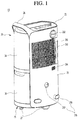
- FIG. 1 is a front perspective view of an external form of a dehumidifier according to a first embodiment of the present disclosure.
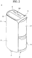
- FIG. 2 is a rear perspective view of the external form of the dehumidifier according to the first embodiment of the present disclosure.
- FIG. 3 is an exploded perspective view of an internal structure of the dehumidifier according to the first embodiment of the present disclosure.
- a dehumidifier 10 has an external appearance which is formed by a main body 20 (e.g., a "case").
- the main body 20 includes an upper panel 21 which forms an external appearance of an upper surface.
- a discharge port 211 through which air in the main body 20 is discharged may be formed at the main body 20.
- the main body 20 may further include a front panel 23 which forms an external appearance of a front surface.
- An inlet port 231 through which air outside the main body 20 enters may be formed at the front panel 23.
- the main body 20 may further include a rear panel 22 which forms an external appearance of a surface opposite to the front panel 23.
- the main body 20 may further include a side panel 24 which forms a part of an external appearance of a left side surface.
- the main body 20 may further include a base 25 which forms an external appearance of a lower surface.
- An upper handle 26 by which the main body 20 may be gripped may be formed to protrude at an upper portion of the main body 20, and wheels 27 for movement may be provided at the base 25.
- One end of the upper handle 26 may be formed at an edge portion at which an upper end of the front panel 23 meets a front end of the upper panel 21, and the other end of the upper handle 26 may be formed at an edge portion at which an upper end of the rear panel 22 meets a rear end of the upper panel 21.
- a louver may be installed at the discharge port 211.
- the louver may open and close the discharge port 211 and may also control a discharging direction of the air discharged from the main body 20 to an external space.
- a control panel 211 b may be provided at a certain position of the upper panel 21 which is spaced apart from the discharge port 211.
- a second discharge port 232 may be further formed at an upper portion of the front panel 23.
- a discharging accessory may be coupled to the second discharge port 232, so that the dehumidified air is discharged through the discharging accessory.
- a cap may be installed at the second discharge port 232 and may selectively open and close the second discharge port 232.
- the dehumidified air discharged through the second discharge port 232 may be guided by the discharging accessory and may be discharged to a space needing dehumidifcation. It is understood that the invention is not limited to the shapes and positions of the inlet and discharge ports 231 211 illustrated in the drawings.
- the inlet port 231 may be formed in a grille-like shape to prevent foreign objects from entering an internal space of the main body 20.
- An air filter 233 which filters foreign objects contained in the air passing through the inlet port 231 may be provided at the inlet port 231.
- the air filter 233 may be formed in a mesh-like shape to filter the foreign objects contained in the air passing through the inlet port 231, and thus only clean air from which the foreign substances are removed may enter the internal space of the main body 20.
- the air filter 233 may be inserted into and installed in the main body, and a user may withdraw the air filter 233, wash and dry the air filter 233, and then reuse the air filter 233.
- a filter guide 238 which guides inserting and withdrawing of the air filter 233 may be formed at the front panel 23.
- the air filter 233 may be inserted into or withdrawn from the internal space of the main body 20 through a gap between the filter guide 239 and the inlet port 231.
- the filter guide 238 is formed to extend laterally, the foreign objects are prevented by the filter guide 238 from entering the internal space of the main body even when the foreign objects enters a space in which the air filter 233 is inserted.
- a humidity sensor 234 which senses humidity of a space at which the dehumidifier 10 is installed may be further installed at the front panel 23.
- a display unit may display the amount of humidity which is sensed by the humidity sensor 234.
- a power cord unit 235 may be formed at the front panel 23.
- the power cord unit 235 may include a cord fixing part 236 around which a power cord for supplying electric power into the main body 20 is wound and a cord insertion part 237 into which the power cord is temporarily inserted and fixed.
- the base 25 which forms the external appearance of the lower surface is installed at lower ends of the front panel 23 and the rear panel 22, and the side panel 24 which forms a part of the external appearance of the side surface may be installed at right ends of the front panel 23 and the rear panel 22.
- a water tank 30 which accommodates water condensation generated during a dehumidifying process of the air may be provided at a lower side of the side panel 24. A portion of the external appearance of the side surface of the main body 20 may be formed by the water tank 30.
- a heat exchange unit 40 which exchanges heat with the air introduced through the inlet port 231 and a fan assembly 50 which enables the air to flow from the inlet port 231 and the discharge port may be provided inside the main body 20.
- the air passing through the heat exchange unit 40 exchanges heat with a refrigerant flowing through the heat exchange unit 40, and a temperature thereof is lowered. As a result, moisture contained in the air is condensed, and thus the air is converted into a dry state.
- the fan assembly 50 which provides a flow of the air in the main body 20 may be installed at one side of the heat exchange unit 40.
- the fan assembly 50 When the fan assembly 50 is operated, external air is suctioned into the main body 20 through the inlet port 231, and the air suctioned in is dehumidified while passing through the heat exchange unit 40. The dehumidified air is discharged to the external space through the discharge port 211.
- a frame 60 which supports the heat exchange unit 40 and the fan assembly 50 may be provided at a lower side of the heat exchange unit 40 and a fan assembly 50.
- the frame 60 may be located at the lower side of the heat exchange unit 40 and the fan assembly 50, and the heat exchange unit 40 and the fan assembly 50 may be supported by an upper surface of the frame 60.
- the frame 60 may include an upper frame 61 which supports the heat exchange unit 40 and the fan assembly 50, and a lower frame 62 which separates a lower space of the upper frame 61 into a compressor chamber 70, an electronic component chamber 80, and a water tank chamber 90.
- the upper frame 61 may be separated into a portion at which the fan assembly 50 is supported and a portion at which the heat exchange unit 40 is supported.
- the portion at which the heat exchange unit 40 is supported may function as a drain pan into which the condensate water falling from the heat exchange unit 40 drain collects.
- an upper surface of the portion at which the heat exchange unit 40 is supported may be sloped with a predetermined tilt to enable the condensate water falling from the heat exchange unit 40 to be gathered at a specific position.
- the condensate water gathered by the slope of the upper surface of the upper frame 61 falls down and is guided to an upper surface of the water tank 30.
- the condensate water falling to the water tank 30 is stored in the water tank 30.
- a lower half portion of the internal space of the main body 20 may be separated by the lower frame 62 into the electronic component chamber 80, the compressor chamber 70, and the water tank chamber 90.
- the electronic component chamber 80, the compressor chamber 70 and the water tank chamber 90 may be arranged in a row, but are not limited to such arrangement.
- An upper portion of the lower frame 62 may be supported by the upper frame 61, and a lower end thereof may be supported by the base 25.
- the lower frame 62 may be installed to cross a space formed by the front panel 23 and the rear panel 22 in forward and backward directions and thus separate the lower half portion of the internal space of the main body 20 into three sections in left and right directions of the main body 20.
- the upper frame 61 and the lower frame 62 may be formed in an approximately "n" shape when seen from a front side, but is not limited to such shape.
- the upper and lower frames 61 and 62 may also be formed so that the heat exchange unit 40 and the fan assembly 50 are located at an upper side thereof and the electronic component chamber 80, and the compressor chamber 70 and the water tank chamber 90 are located at a lower side thereof. Accordingly, the electronic component chamber 80 and the water tank chamber 90 may be located at left and right sides based on the compressor chamber 70.
- a compressor 71 which compresses the refrigerant flowing inside the heat exchange unit 40 may be provided at the compressor chamber 70.
- a plurality of electronic components may be provided at the electronic component chamber 80.
- a main board 81 for controlling the plurality of electronic components may be provided at the electronic component chamber 80.
- the main board 81 may be covered by a control case 82 which protects the main board 81 from an external shock.
- the main board 81 may be provided in the control case 82, and an opposite side to the control case 82 may be covered by a control cover (not shown) to protect the main board 81 from the external shock.
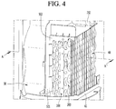
- FIG. 4 is a diagram illustrating a state in which a heat exchanger of the dehumidifier according to the first embodiment of the present disclosure is coupled to the fan assembly when viewed from a left side.
- FIG. 5 is a diagram illustrating the state in which the heat exchanger of the dehumidifier according to the first embodiment of the present disclosure is coupled to the fan assembly when viewed from a right side.
- FIG. 6 is a cross-sectional view taken along a line A-A' of FIG. 4 .
- the heat exchange unit 40 and the fan assembly 50 are supported at an upper side of the upper frame 61.
- the heat exchange unit 40 may be provided at a front of the fan assembly 50 and may be located inside the inlet port 231.
- the fan assembly 50 may include a fan motor 51 which generates a driving force, a hub 52 which is coupled to the fan motor 51, a plurality of blades 53 which are provided at an outer circumferential surface of the hub 52 to be spaced apart from each other, a fan inlet part 54 which introduces the air into the fan assembly 50, and a guide unit 55 which is located at a front end of the blades 53 to guide introduction of the air.
- the fan inlet part 54 forms a front end of the guide unit 55.
- the dehumidifier 10 may further include a blocking wall 501 which is installed at a front outer circumferential surface of the fan assembly 50.
- the blocking wall 501 may block the air passed through the heat exchange unit 40 from flowing to an outside of the fan assembly 50.
- the blocking wall 501 may be surround an outside of a boundary between the heat exchange unit 40 and the guide unit 55. Therefore, the air passed through the heat exchange unit 40 may be guided to the fan inlet part 54 by the blocking wall 501.
- the dehumidifier 10 may include a supporting part 502 which supports an outside of the heat exchange unit 40.
- the supporting part 502 may extend along an outer surface of the heat exchange unit 40 from the blocking wall 501.
- the supporting part 502 may be attached to an upper surface and a side surface of the heat exchange unit 40 and may support the heat exchange unit 40.
- a front surface of the supporting part 502 may be in contact with a rear surface of the front panel 23.
- the second discharge port 232 may be formed at an upper portion of the supporting part 502.
- the supporting part 502 and the second discharge port 232 may be integrally formed.
- the heat exchange unit 40 may include a condenser 100 which condenses the refrigerant compressed by the compressor 71 and an evaporator 200 which is installed close to the condenser 100 in a direction of the inlet port 231 and evaporates the refrigerant expanded in the expander.
- the condenser 100 may be provided at a front side of the fan assembly 50 corresponding to a position of the fan assembly 50. That is, the fan inlet part 54 of the fan assembly 50 may be located at a side of an outlet port of the condenser based on an air flowing direction.
- the condenser 100 may form a plurality of rows and include a tube 110 through which the refrigerant flows and a fin 120 to which the tube 110 is coupled.
- the tube 110 may have a plurality of rows.
- the tube 110 may be arranged having three rows.
- the tube 110 in each row may be arranged to be vertically spaced apart from each other.
- the tube 110 may include a plurality of first row tubes 111 which are arranged to form a first row, a plurality of second row tubes 112 which are provided at one side of the plurality of first row tubes and form a second row, and a plurality of third row tubes 113 which are provided at one side of the plurality of second row tubes and form a third row.
- the first row tubes 111 is the closest distance to the evaporator 200. Also, it is understood that, among the first to third row tubes 111, 112 and 113, the third row tubes 113 is the closest distance to the fan assembly 50.
- the second row tubes 112 are located between the first row tubes 111 and the third row tubes 113.
- the air introduced through the inlet port 231 of the front panel 23 passes through the evaporator 200 and then passes through the condenser 100 in the order of the first row tubes 111, the second row tubes 112, and the third row tubes 113, and then moves to the fan assembly 50.
- Each of the plurality of rows of tube 110 may be formed to have the same shape and size or may be formed to have a different shape and size.
- each of the plurality of rows of tube 110 may have a circular pipe-like shape but is not limited thereto.
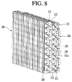
- a refrigerant inlet port 115 is formed at the third row tubes 113 of the condenser 100, and a refrigerant discharge port 116 is formed at the first row tubes 113.
- the refrigerant introduction port 115 may be connected to a tube located at an uppermost side among the third row tubes 113.
- the refrigerant discharge port 116 may be connected to a tube located at a lowermost side among the first row tubes 111.
- the refrigerant is introduced into the condenser 100 through the refrigerant introduction port 115, passes, in turn, through the third row tubes 113, the second row tubes 112, and the first row tubes 111, and is discharged through the refrigerant discharge port 116.
- the refrigerant in the first row tubes 111 forms a gas or two-phase refrigerant section
- the refrigerant in the second row tubes 112 forms a two-phase or liquid refrigerant section
- the refrigerant in the third row tubes 113 forms a liquid or supercooled refrigerant section.
- the fin 120 may be formed having a thin plate shape and a tube through-hole in which the tube 110 is accommodated.
- the fin 120 may extend vertically and may be arranged to be spaced apart in left and right directions.
- the fins 120 may form a plurality of rows corresponding to the plurality of rows of tube 110. Each of the fins 120 forming each row may be separated from each other. For example, the plurality of rows includes three rows, but is not limited thereto.
- the fins 120 having the three rows includes a first row fin 121 in which the first row tubes 111 are inserted, a second row fin 122 in which the second row tubes 112 are inserted, and a third row fin 123 in which the third row tubes 113 are inserted.
- the first to third row fins include a plurality of fins which are horizontally stacked.
- the first row fin 121 may be located closest to the evaporator 200, and the second row fin 122 and the third row fin 123 may be located gradually closer to the fan assembly 50 (e.g., third row fin 123 may be located closer to the fan assembly 50 than the second row fin 122).
- the first to third row fins 121, 122 and 123 may be formed separately from each other.
- the fins forming the plurality of rows may be completely separated from each other such that the heat of tubes forming one row is restricted from being transferred to other tubes forming another row. As such, heat transfer between the refrigerants may be minimized, and heat exchange efficiency may be enhanced.
- the evaporator 200 may be provided at a front side of the condenser 100 to be spaced apart from the condenser 100 and to face the condenser 100.
- a distance between the evaporator 200 and the condenser 100 may be about 10mm. It is understood that the distance is not limited thereto.
- the evaporator 200 may include a tube 200a which forms a plurality of rows and through which the refrigerant flows, and a fin 200b at which the tube 200a is coupled.
- the plurality row includes two rows. It is understood that the plurality of rows is not limited to two rows.
- the condenser 100 and the evaporator 200 which are spaced apart from each other may be fixed to predetermined positions by the supporting part 502.
- the air passing through the evaporator 200 exchanges heat with the refrigerant flowing inside the evaporator 200, which lowers a temperature thereof.
- the temperature of air passing through the evaporator 200 is lowered, the moisture contained in the air is condensed and forms a dew on a surface of the evaporator 200.
- the air having the lowered humidity and temperature while passing through the evaporator 200 may pass through a drying process while passing through the condenser 100. As a result, the moisture contained in the air is condensed, and thus the air is changed into the dry state.
- FIG. 7 is a state diagram illustrating shapes of the condenser and the evaporator of the dehumidifier according to the first embodiment of the present disclosure when seen from a left side.
- FIG. 8 is a state diagram illustrating the shape of the condenser and the evaporator of the dehumidifier according to the first embodiment of the present disclosure when seen from a right side.
- the dehumidifier 10 includes an evaporator fixing part 210.
- the evaporator fixing part 210 may be formed to fix the tube 200a included in the evaporator 200.
- the evaporator fixing part 210 may be provided at both sides of the tube 200a.
- the tube 200a may be coupled to one evaporator fixing part 210 and may extend to the other evaporator fixing part 210, and then may extend again to the one evaporator fixing part 210 after a direction change.
- the condenser 100 may include a condenser fixing part 130 which fixes the tube 110 included in the condenser 100.
- the condenser fixing part 130 may include a first fixing part 131 which is coupled to one side of the tube 110 and a second fixing part 132 which is coupled to the other side.
- the tube 110 may extend in a horizontal direction from the first fixing part 131 toward the second fixing part 132.
- the first fixing part 131 may include a first through-hole 131 a through which the tube forming the plurality of rows passes. That is, the first through-hole 131 a may be formed so that the tube forming the three rows is inserted therein.
- the second fixing part 132 may include a second through-hole 132a through which the first row tubes 111 are fixed. That is, only the first row tubes 111 are fixed to the second fixing part 132. However, because the first row tubes 111 are connected to the second and third row tubes 112 and 113, a support for the second and third row tubes 112 and 113 may be maintained even through only the first row tubes 111 are supported by the second fixing part 132. Thus, the second and third row tubes 112 and 113 may not be fixed to the second fixing part 132.
- the first row tubes 111 may be fixed to the first fixing part 131 and extend to the second fixing part 132 and then extend again to the first fixing part 131 after a direction change.
- the part of the tube at which the direction is changed may be referred to as a bending tube.
- the second and third row tubes 112 and 113 may also include the bending tubes. However, because the second and third row tubes 112 and 113 are not supported by the second fixing part 132, the second and third row tubes 112 and 113 extend from the first fixing part 131 toward one side and then extend again to the first fixing part 131 after the direction change.
- a width of the first fixing part 131 is wider than a width of the second fixing part 132.
- the width of the first fixing part 131 may be three times larger than that of the second fixing part 132. It is understood that the width of the first fixing part 131 is not limited to being three times larger than that of the second fixing part 132.
- each of the first to third row tubes 111, 112 and 113 is each fixed to the first fixing part 131, and the other side portion of each of the first to third row tubes 111, 112 and 113 has a degree of freedom which is relatively movable with respect to each other. Therefore, when the condenser 100 is installed inside the case, a degree of installation freedom is provided, a distance between the fins 120 is ensured, and thus the heat transfer between the fins 120 may be prevented.
- the evaporator fixing part 210 and the condenser fixing part 130 may be coupled by a first fastening member 150.
- one evaporator fixing part 210 and the first fixing part 131 may be coupled by one first fastening member 150, and another evaporator fixing part 210 and the second fixing part 132 may be coupled by another first fastening member 150.
- a first fastening hole 220 at which the one first fastening member 150 is coupled is formed at the one evaporator fixing part 210.
- the first fastening hole 220 is also formed at the other evaporator fixing part 210.
- a plurality of first fastening holes 220 may be provided and arranged vertically, and a plurality of one first fastening member 150 may be provided corresponding to the plurality of first fastening holes 220.
- the evaporator 200 may be arranged spaced apart from the condenser 100 at a preset distance.
- a second fastening hole 221 for coupling with the supporting part 502 may be formed at the evaporator fixing part 210.
- the second fastening hole 221 may be formed at an upper portion of the evaporator fixing part 210.
- the evaporator fixing part 210 and the supporting part 502 may be coupled by a second fastening member 151.
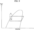
- FIG. 9 is a P-H diagram of the dehumidifier according to the first embodiment of the present disclosure.
- Table 1 shows comparative data of a condensing capacity, condensing efficiency and a temperature of a refrigerant outlet end in a case in which an integrated fin according to the related art is provided and a case in which a three-row fin according to the present disclosure is provided.
- the integrated fin is a structure in which a fin having one row is coupled to a tube having three rows.
- a heat exchange capacity in the related art is 14.85 [kcal/h]
- a capacity in the three-row fin embodiment is 16.32 [kcal/h]
- the capacity is increased by 10%
- the related art is 1.95 [L/HrKw]
- the three-row fin embodiment is 2.24 [L/HrKw], and thus it is increased by 15%.
- the related art is 30.5 [°C]
- the three-row fin embodiment is 20.6 [°C]
- it is reduced by 9.9 [°C] and thus a supercooling degree may be further ensured. Therefore, it may be understood that performance of the condenser 100 is enhanced.
- a thin dotted line is a P-H diagram according to the related art
- a thick dotted line is a P-H diagram according to the three-row fin embodiment.
- the supercooling degree AT2 of present disclosure is greater than the ⁇ T1 of the related art by 9.9 [°C], and thus it may be understood that the performance is enhanced.
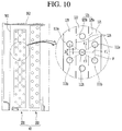
- FIG. 10 is a cross-sectional view of a condenser of a dehumidifier according to a second embodiment of the present disclosure.
- a fin 120 according to a second embodiment of the present disclosure may include a connection part 125 which couples two adjacent fins 120 and a cut-away part 126 which is formed between two adjacent connection parts 125.
- connection part 125 may include a first connection part 125a formed between the first row fin 121 and the second row fin 122, and a second connection part 125b formed between the second row fin 122 and the third row fin 123.
- the first row fin 121 forms a row located at the rightmost side and the third row fin 123 forms a row located at the leftmost side. It is also understood that the second row fin 122 is located between the first and third row fins 121 and 123.
- At least a portion of the first row fin 121 and at least a portion of the second row fin 122 are coupled by the first connection part 125a and may be spaced apart from each other by one cut-away part 126.
- At least a portion of the second row fin 122 and at least a portion of the third row fin 123 are coupled by the second connection part 125b and may be spaced apart from each other by the other cut-away part 126.
- the one cut-away part 126 located at a rear of the first row fin 121 may restrict the heat transfer from the second row fin 122 to the first row fin 121, and the other cut-away part 126 located at a rear of the second row fin 122 may restrict the heat transfer from the third row fin 123 to the second row fin 122.
- the first connection part 125a and the second connection part 125b are formed at heights corresponding to each other based on a vertical length of the fin.
- a plurality of cut-away parts 126 may be provided spaced apart from each other.
- the plurality of cut-away parts 126 may be located between the plurality of fins 120 and may be arranged in a row to be spaced apart from each other.
- the plurality of first, second, and third row tubes 111, 112 and 113 are arranged in parallel, and the plurality of cut-away parts 126 may be arranged in parallel with the plurality of first, second, and third row tubes 111, 112 and 113.
- an arrangement of the plurality of cut-away parts 126 is not limited thereto. Other arrangements having a configuration for restricting the heat exchange through the fins 120 and separating the fins 120 from each other are allowed.
- one of the second row tubes 112 is referred to as a second row reference tube 112c
- two of the first row tubes 111 located closest to the second row reference tube 112c are referred to as a first row upper tube 111 a and a first row lower tube 111 b
- two of the third row tubes 113 located closest to the second row reference tube 112c are referred to as a third row upper tube 113a and a third row lower tube 113b.
- first row upper tube 111 a and the third row upper tube 113a may be located at upper sides relative to the first row lower tube 111 b and the third row lower tube 113b, respectively.
- connection part 125 meets a first imaginary extension line l1 which extends horizontally from a center of the second row reference tube 112c. That is, the first connection part 125a is formed along the first extension line l1 between one corner of the first row fin 121 and one corner of the second row fin 122, and the second connection part 125b is formed along the first extension line l1 between the other corner of the second row fin 122 and one corner of the third row fin 123.
- connection part 125 has a preset vertical length t based on the first extension line l1 and thus has a total length of 2t.
- a length of t may be smaller than a radius r of one tube.
- the cut-away part 126 may be formed to have a certain shape between two adjacent connection parts 125.
- the cut-away part 126 may intersect with a second imaginary extension line l2 which extends from a center of the first row upper tube 111 a toward a center of the third row lower tube 113b and also intersect with a third imaginary extension line l3 which extends from a center of the first row lower tube 111 b toward a center of the third upper lower tube 113a.
- the cut-away part 126 blocks the shortest routes l2 and l3 on the fins 120 through which the heat is transferred and thus reduces the heat transfer due to the fin 120 of the tube. Also, since the connection part 125 which is not cut away is provided, damage and deformation of the fin 120 may be prevented.
- FIG. 11 is a cross-sectional view of a condenser of a dehumidifier according to a third embodiment of the present disclosure.
- the embodiment of Fig. 11 is different from the second embodiment regarding the arrangement of the connection part 125 and thus a description thereof will be provided with an emphasis on the difference.
- the description that is the same as that for the second embodiment are referred to the description and the reference numerals of the second embodiment.
- a first connection part 125a and a second connection part 125b according to a third embodiment are provided at different heights from each other. That is, the first connection part 125a and the second connection part 125b are disposed in the form of a zigzag in a vertical direction.
- One of the first connection part 125a and the second connection part 125b may be located on a first imaginary extension line l1 which extends horizontally from a center of the second row reference tube 112c, and the other one of the first connection part 125a and the second connection part 125b may be located on a fourth imaginary extension line l4 which extends from a center of the first row upper tube 111a toward a center of the third row upper tube 113a.
- first connection part 125a may be located on the fourth extension line l4, and the second connection part 125b may be located on the first extension line l1. That is, the first connection part 125a may be located on the fourth extension line l4 which extends backward from one of the first row tubes 111, and the second connection part 125b may be located on the first extension line l1 which extends backward from one of the second row tubes 112.
- first connection part 125a may be located on the first extension line l1
- second connection part 125b may be located on the fourth extension line l4. That is, the first connection part 125a may be located on the first extension line l1 which extends forward from one of the second row tubes 112, and the second connection part 125b may be located on the fourth extension line l4 which extends forward from one of the third row tubes 113.
- the cut-away part 126 intersects the second extension line l2 and the third extension line l3 which are the shortest distances between the tubes. The heat transfer through the shortest distances thus may be prevented.
Abstract
Description
- The present disclosure relates to a dehumidifier.
- A dehumidifier is a home appliance which suctions in air, removes moisture contained in the air, and then discharges the dehumidified air.
- A refrigeration cycle is driven in the dehumidifier. The refrigeration cycle may include a compressor to compress a refrigerant, a condenser to condense the compressed refrigerant, an expander to expand the condensed refrigerant, and an evaporator to evaporate the expanded refrigerant.
- The dehumidifier then suctions and passes the air through a heat exchanger that includes the condenser and the evaporator. The air then exchanges heat with the refrigerant flowing through the heat exchanger, which removes the moisture in the air.
- The evaporator absorbs the ambient heat and evaporates a liquid refrigerant. Therefore, a temperature of the air that passes through the evaporator is lowered through the heat exchange with the refrigerant. As the temperature of the air passing through the evaporator is lowered, the moisture contained in the air is condensed, and a dew forms on a surface of the evaporator. The air which has humidity and temperature lowered while passing through the evaporator is also heated while passing through the condenser.
- The condenser generally includes a tube through which the refrigerant flows, and a fin to which the tube is coupled. A plurality of rows of tubes may be coupled to the fin. Conventionally, heat conduction through the fin occurs in the plurality of rows of tubes. As a result, a heat exchange rate between the refrigerant flowing through the tubes and the air is reduced, refrigerant condensing efficiency is also reduced, and thus the dehumidification performance is reduced.
- The present disclosure is directed to a dehumidifier having an improved dehumidification performance.
- According to an aspect of the present disclosure, a dehumidifier includes a case having an inlet port and a discharge port, a compressor to compress a refrigerant, a condenser to condense the compressed refrigerant, an expander to expand the condensed refrigerant, an evaporator to evaporate the expanded refrigerant, and a fan to provide an airflow from the inlet port to the discharge port, wherein the condenser includes a tube through which the refrigerant flows, the tube formed having a plurality of rows of tubes, and a fin to exchange heat, the fin being attached to the tube, the fin Including a first row fin attached to a first row of tubes among the plurality of rows of tubes, and a second row fin attached to a second row of tubes among the plurality of rows of tubes, whereby at least a portion of the first row fin is separate from the second row fin.
- According to another aspect of the present disclosure, a condenser for a dehumidifier includes a tube through which a refrigerant flows, the tube formed having a first, second, and third row of tubes, a fin to exchange heat, the fin being attached to the tube, wherein the fin includes a first row fin attached to the first row of tubes, a second row fin attached to the second row of tubes, the second row fin being separate from at least a portion of the first row fin, a third row fin attached to the third row of tubes, the third row fin having at least a portion thereof being separate from the second row fin.
- The condenser may further include a condenser fixing part to support the tube, wherein the condenser fixing part may include a first fixing part to support a first side of the tube and a second fixing part to support a second side of the tube.
- The first fixing part may support the first sides of the first, second, and third row tubes, and the second fixing part may support the second side of the first row tubes and is spaced apart from the second and third row tubes.
- A width of the first fixing part may be larger than a width of the second fixing part.
- A first side of the second and third row tubes may be supported at the first fixing part, and the other sides of the second and third row tubes may be movable with respect to the first fixing part.
- A blocking wall may be provided at an outer circumferential surface of the fan assembly and blocks the air from flowing to an outside of the fan assembly; and a supporting part may be provided to support outside surfaces of the evaporator and the condenser.
- The evaporator may comprise an evaporator fixing part to support a tube of the evaporator, whereby the evaporator fixing part may be coupled with the condenser fixing part by a first fastening member and coupled with the supporting part by a second fastening member.
- The fin may further comprise a connection part to couple two adjacent fins, whereby the connection part may comprise a first connection part to connect the first row fin with the second row fin, and a second connection part to connect the second row fin with the third row fin.
- The first connection part and the second connection part may be provided parallel to each other or at heights corresponding to each other.
- The first and second connection parts may be provided at an extension line which extends forward and backward from one of the second row tubes.
- The first and second connection parts may be provided at different heights from each other.
- The first connection part may be provided at a first extension line which extends backward from one of the first row tubes, and the second connection part may be provided at a second extension line which extends backward from one of the second row tubes.
- The first connection part may be provided at a first extension line which extends forward from one of the second row tubes, and the second connection part may be provided at a second extension line which extends forward from one of the third row tubes.
- The accompanying drawings, which are included to provide a further understanding of the invention and are incorporated in and constitute a part of this application, illustrate embodiment(s) of the invention and together with the description serve to explain the principle of the invention. In the drawings:
-
FIG. 1 is a front perspective view of an external form of a dehumidifier according to a first embodiment of the present disclosure; -
FIG. 2 is a rear perspective view of the form of the dehumidifier according to the first embodiment of the present disclosure; -
FIG. 3 is an exploded perspective view of an internal structure of the dehumidifier according to the first embodiment of the present disclosure; -
FIG. 4 is a state diagram illustrating a state in which a heat exchanger of the dehumidifier according to the first embodiment of the present disclosure is coupled to a fan assembly when seen from a left side; -
FIG. 5 is a state diagram illustrating the state in which the heat exchanger of the dehumidifier according to the first embodiment of the present disclosure is coupled to the fan assembly when seen from a right side; -
FIG. 6 is a cross-sectional view taken along a line A-A' ofFIG. 4 ; -
FIG. 7 is a state diagram illustrating shapes of a condenser and an evaporator of the dehumidifier according to the first embodiment of the present disclosure when seen from a left side; -
FIG. 8 is a state diagram illustrating the shape of the condenser and the evaporator of the dehumidifier according to the first embodiment of the present disclosure when seen from a right side; -
FIG. 9 is a P-H diagram of the dehumidifier according to the first embodiment of the present disclosure; -
FIG. 10 is a cross-sectional view of a condenser of a dehumidifier according to a second embodiment of the present disclosure; and -
FIG. 11 is a cross-sectional view of a condenser of a dehumidifier according to a third embodiment of the present disclosure. - Advantages, features, and methods for achieving those of embodiments may become apparent upon referring to embodiments described later in detail together with the attached drawings. However, embodiments are not limited to the embodiments disclosed hereinafter, but may be embodied in different modes. The same reference numbers may refer to the same elements throughout the specification.
-
FIG. 1 is a front perspective view of an external form of a dehumidifier according to a first embodiment of the present disclosure.FIG. 2 is a rear perspective view of the external form of the dehumidifier according to the first embodiment of the present disclosure.FIG. 3 is an exploded perspective view of an internal structure of the dehumidifier according to the first embodiment of the present disclosure. - Referring to
FIGS. 1 to 3 , adehumidifier 10 has an external appearance which is formed by a main body 20 (e.g., a "case"). Themain body 20 includes anupper panel 21 which forms an external appearance of an upper surface. Adischarge port 211 through which air in themain body 20 is discharged may be formed at themain body 20. - The
main body 20 may further include afront panel 23 which forms an external appearance of a front surface. Aninlet port 231 through which air outside themain body 20 enters may be formed at thefront panel 23. - The
main body 20 may further include arear panel 22 which forms an external appearance of a surface opposite to thefront panel 23. Themain body 20 may further include aside panel 24 which forms a part of an external appearance of a left side surface. Themain body 20 may further include abase 25 which forms an external appearance of a lower surface. - An
upper handle 26 by which themain body 20 may be gripped may be formed to protrude at an upper portion of themain body 20, andwheels 27 for movement may be provided at thebase 25. - One end of the
upper handle 26 may be formed at an edge portion at which an upper end of thefront panel 23 meets a front end of theupper panel 21, and the other end of theupper handle 26 may be formed at an edge portion at which an upper end of therear panel 22 meets a rear end of theupper panel 21. - A louver may be installed at the
discharge port 211. The louver may open and close thedischarge port 211 and may also control a discharging direction of the air discharged from themain body 20 to an external space. Acontrol panel 211 b may be provided at a certain position of theupper panel 21 which is spaced apart from thedischarge port 211. - In the
main body 20, asecond discharge port 232 may be further formed at an upper portion of thefront panel 23. A discharging accessory may be coupled to thesecond discharge port 232, so that the dehumidified air is discharged through the discharging accessory. A cap may be installed at thesecond discharge port 232 and may selectively open and close thesecond discharge port 232. - More specifically, when the discharging accessory is coupled to the
second discharge port 232, the dehumidified air discharged through thesecond discharge port 232 may be guided by the discharging accessory and may be discharged to a space needing dehumidifcation. It is understood that the invention is not limited to the shapes and positions of the inlet and dischargeports 231 211 illustrated in the drawings. - The
inlet port 231 may be formed in a grille-like shape to prevent foreign objects from entering an internal space of themain body 20. Anair filter 233 which filters foreign objects contained in the air passing through theinlet port 231 may be provided at theinlet port 231. - The
air filter 233 may be formed in a mesh-like shape to filter the foreign objects contained in the air passing through theinlet port 231, and thus only clean air from which the foreign substances are removed may enter the internal space of themain body 20. Theair filter 233 may be inserted into and installed in the main body, and a user may withdraw theair filter 233, wash and dry theair filter 233, and then reuse theair filter 233. - A
filter guide 238 which guides inserting and withdrawing of theair filter 233 may be formed at thefront panel 23. Theair filter 233 may be inserted into or withdrawn from the internal space of themain body 20 through a gap between the filter guide 239 and theinlet port 231. - Since the
filter guide 238 is formed to extend laterally, the foreign objects are prevented by thefilter guide 238 from entering the internal space of the main body even when the foreign objects enters a space in which theair filter 233 is inserted. - A
humidity sensor 234 which senses humidity of a space at which thedehumidifier 10 is installed may be further installed at thefront panel 23. A display unit may display the amount of humidity which is sensed by thehumidity sensor 234. - A
power cord unit 235 may be formed at thefront panel 23. Thepower cord unit 235 may include acord fixing part 236 around which a power cord for supplying electric power into themain body 20 is wound and acord insertion part 237 into which the power cord is temporarily inserted and fixed. - The base 25 which forms the external appearance of the lower surface is installed at lower ends of the
front panel 23 and therear panel 22, and theside panel 24 which forms a part of the external appearance of the side surface may be installed at right ends of thefront panel 23 and therear panel 22. - A
water tank 30 which accommodates water condensation generated during a dehumidifying process of the air may be provided at a lower side of theside panel 24. A portion of the external appearance of the side surface of themain body 20 may be formed by thewater tank 30. - A
heat exchange unit 40 which exchanges heat with the air introduced through theinlet port 231 and afan assembly 50 which enables the air to flow from theinlet port 231 and the discharge port may be provided inside themain body 20. - The air passing through the
heat exchange unit 40 exchanges heat with a refrigerant flowing through theheat exchange unit 40, and a temperature thereof is lowered. As a result, moisture contained in the air is condensed, and thus the air is converted into a dry state. - The
fan assembly 50 which provides a flow of the air in themain body 20 may be installed at one side of theheat exchange unit 40. When thefan assembly 50 is operated, external air is suctioned into themain body 20 through theinlet port 231, and the air suctioned in is dehumidified while passing through theheat exchange unit 40. The dehumidified air is discharged to the external space through thedischarge port 211. - A
frame 60 which supports theheat exchange unit 40 and thefan assembly 50 may be provided at a lower side of theheat exchange unit 40 and afan assembly 50. Theframe 60 may be located at the lower side of theheat exchange unit 40 and thefan assembly 50, and theheat exchange unit 40 and thefan assembly 50 may be supported by an upper surface of theframe 60. - The
frame 60 may include anupper frame 61 which supports theheat exchange unit 40 and thefan assembly 50, and alower frame 62 which separates a lower space of theupper frame 61 into acompressor chamber 70, anelectronic component chamber 80, and awater tank chamber 90. - The
upper frame 61 may be separated into a portion at which thefan assembly 50 is supported and a portion at which theheat exchange unit 40 is supported. The portion at which theheat exchange unit 40 is supported may function as a drain pan into which the condensate water falling from theheat exchange unit 40 drain collects. For example, an upper surface of the portion at which theheat exchange unit 40 is supported may be sloped with a predetermined tilt to enable the condensate water falling from theheat exchange unit 40 to be gathered at a specific position. - The condensate water gathered by the slope of the upper surface of the
upper frame 61 falls down and is guided to an upper surface of thewater tank 30. The condensate water falling to thewater tank 30 is stored in thewater tank 30. - A lower half portion of the internal space of the
main body 20 may be separated by thelower frame 62 into theelectronic component chamber 80, thecompressor chamber 70, and thewater tank chamber 90. Theelectronic component chamber 80, thecompressor chamber 70 and thewater tank chamber 90 may be arranged in a row, but are not limited to such arrangement. - An upper portion of the
lower frame 62 may be supported by theupper frame 61, and a lower end thereof may be supported by thebase 25. - The
lower frame 62 may be installed to cross a space formed by thefront panel 23 and therear panel 22 in forward and backward directions and thus separate the lower half portion of the internal space of themain body 20 into three sections in left and right directions of themain body 20. - The
upper frame 61 and thelower frame 62 may be formed in an approximately "n" shape when seen from a front side, but is not limited to such shape. The upper andlower frames heat exchange unit 40 and thefan assembly 50 are located at an upper side thereof and theelectronic component chamber 80, and thecompressor chamber 70 and thewater tank chamber 90 are located at a lower side thereof. Accordingly, theelectronic component chamber 80 and thewater tank chamber 90 may be located at left and right sides based on thecompressor chamber 70. - Meanwhile, a
compressor 71 which compresses the refrigerant flowing inside theheat exchange unit 40 may be provided at thecompressor chamber 70. A plurality of electronic components may be provided at theelectronic component chamber 80. - For example, a
main board 81 for controlling the plurality of electronic components may be provided at theelectronic component chamber 80. Themain board 81 may be covered by acontrol case 82 which protects themain board 81 from an external shock. Themain board 81 may be provided in thecontrol case 82, and an opposite side to thecontrol case 82 may be covered by a control cover (not shown) to protect themain board 81 from the external shock. -
FIG. 4 is a diagram illustrating a state in which a heat exchanger of the dehumidifier according to the first embodiment of the present disclosure is coupled to the fan assembly when viewed from a left side.FIG. 5 is a diagram illustrating the state in which the heat exchanger of the dehumidifier according to the first embodiment of the present disclosure is coupled to the fan assembly when viewed from a right side.FIG. 6 is a cross-sectional view taken along a line A-A' ofFIG. 4 . - Referring to
FIGS. 4 to 6 , theheat exchange unit 40 and thefan assembly 50 are supported at an upper side of theupper frame 61. Theheat exchange unit 40 may be provided at a front of thefan assembly 50 and may be located inside theinlet port 231. - The
fan assembly 50 may include afan motor 51 which generates a driving force, ahub 52 which is coupled to thefan motor 51, a plurality ofblades 53 which are provided at an outer circumferential surface of thehub 52 to be spaced apart from each other, afan inlet part 54 which introduces the air into thefan assembly 50, and aguide unit 55 which is located at a front end of theblades 53 to guide introduction of the air. Thefan inlet part 54 forms a front end of theguide unit 55. - The
dehumidifier 10 may further include a blockingwall 501 which is installed at a front outer circumferential surface of thefan assembly 50. The blockingwall 501 may block the air passed through theheat exchange unit 40 from flowing to an outside of thefan assembly 50. - The blocking
wall 501 may be surround an outside of a boundary between theheat exchange unit 40 and theguide unit 55. Therefore, the air passed through theheat exchange unit 40 may be guided to thefan inlet part 54 by the blockingwall 501. - The
dehumidifier 10 may include a supportingpart 502 which supports an outside of theheat exchange unit 40. The supportingpart 502 may extend along an outer surface of theheat exchange unit 40 from the blockingwall 501. For example, the supportingpart 502 may be attached to an upper surface and a side surface of theheat exchange unit 40 and may support theheat exchange unit 40. - A front surface of the supporting
part 502 may be in contact with a rear surface of thefront panel 23. Thesecond discharge port 232 may be formed at an upper portion of the supportingpart 502. The supportingpart 502 and thesecond discharge port 232 may be integrally formed. - The
heat exchange unit 40 may include acondenser 100 which condenses the refrigerant compressed by thecompressor 71 and anevaporator 200 which is installed close to thecondenser 100 in a direction of theinlet port 231 and evaporates the refrigerant expanded in the expander. - The
condenser 100 may be provided at a front side of thefan assembly 50 corresponding to a position of thefan assembly 50. That is, thefan inlet part 54 of thefan assembly 50 may be located at a side of an outlet port of the condenser based on an air flowing direction. - The
condenser 100 may form a plurality of rows and include atube 110 through which the refrigerant flows and afin 120 to which thetube 110 is coupled. Thetube 110 may have a plurality of rows. For example, thetube 110 may be arranged having three rows. Thetube 110 in each row may be arranged to be vertically spaced apart from each other. - Specifically, the
tube 110 may include a plurality offirst row tubes 111 which are arranged to form a first row, a plurality ofsecond row tubes 112 which are provided at one side of the plurality of first row tubes and form a second row, and a plurality ofthird row tubes 113 which are provided at one side of the plurality of second row tubes and form a third row. - It is understood that, among the first to
third row tubes first row tubes 111 is the closest distance to theevaporator 200. Also, it is understood that, among the first tothird row tubes third row tubes 113 is the closest distance to thefan assembly 50. Thesecond row tubes 112 are located between thefirst row tubes 111 and thethird row tubes 113. - The air introduced through the
inlet port 231 of thefront panel 23 passes through theevaporator 200 and then passes through thecondenser 100 in the order of thefirst row tubes 111, thesecond row tubes 112, and thethird row tubes 113, and then moves to thefan assembly 50. - Each of the plurality of rows of
tube 110 may be formed to have the same shape and size or may be formed to have a different shape and size. For example, each of the plurality of rows oftube 110 may have a circular pipe-like shape but is not limited thereto. - Referring to
FIG. 8 , arefrigerant inlet port 115 is formed at thethird row tubes 113 of thecondenser 100, and arefrigerant discharge port 116 is formed at thefirst row tubes 113. For example, therefrigerant introduction port 115 may be connected to a tube located at an uppermost side among thethird row tubes 113. Therefrigerant discharge port 116 may be connected to a tube located at a lowermost side among thefirst row tubes 111. - Therefore, the refrigerant is introduced into the
condenser 100 through therefrigerant introduction port 115, passes, in turn, through thethird row tubes 113, thesecond row tubes 112, and thefirst row tubes 111, and is discharged through therefrigerant discharge port 116. - The refrigerant in the
first row tubes 111 forms a gas or two-phase refrigerant section, the refrigerant in thesecond row tubes 112 forms a two-phase or liquid refrigerant section, and the refrigerant in thethird row tubes 113 forms a liquid or supercooled refrigerant section. - The
fin 120 may be formed having a thin plate shape and a tube through-hole in which thetube 110 is accommodated. Thefin 120 may extend vertically and may be arranged to be spaced apart in left and right directions. - The
fins 120 may form a plurality of rows corresponding to the plurality of rows oftube 110. Each of thefins 120 forming each row may be separated from each other. For example, the plurality of rows includes three rows, but is not limited thereto. - Specifically, the
fins 120 having the three rows includes afirst row fin 121 in which thefirst row tubes 111 are inserted, asecond row fin 122 in which thesecond row tubes 112 are inserted, and athird row fin 123 in which thethird row tubes 113 are inserted. The first to third row fins include a plurality of fins which are horizontally stacked. - Among the first to
third row fins first row fin 121 may be located closest to theevaporator 200, and thesecond row fin 122 and thethird row fin 123 may be located gradually closer to the fan assembly 50 (e.g.,third row fin 123 may be located closer to thefan assembly 50 than the second row fin 122). - The first to
third row fins - The fins forming the plurality of rows may be completely separated from each other such that the heat of tubes forming one row is restricted from being transferred to other tubes forming another row. As such, heat transfer between the refrigerants may be minimized, and heat exchange efficiency may be enhanced.
- The
evaporator 200 may be provided at a front side of thecondenser 100 to be spaced apart from thecondenser 100 and to face thecondenser 100. For example, according to an embodiment of the disclosure, a distance between theevaporator 200 and thecondenser 100 may be about 10mm. It is understood that the distance is not limited thereto. - The
evaporator 200 may include atube 200a which forms a plurality of rows and through which the refrigerant flows, and afin 200b at which thetube 200a is coupled. For example, according to an embodiment of the disclosure, the plurality row includes two rows. It is understood that the plurality of rows is not limited to two rows. - The
condenser 100 and theevaporator 200 which are spaced apart from each other may be fixed to predetermined positions by the supportingpart 502. The air passing through theevaporator 200 exchanges heat with the refrigerant flowing inside theevaporator 200, which lowers a temperature thereof. As the temperature of air passing through theevaporator 200 is lowered, the moisture contained in the air is condensed and forms a dew on a surface of theevaporator 200. - The air having the lowered humidity and temperature while passing through the
evaporator 200 may pass through a drying process while passing through thecondenser 100. As a result, the moisture contained in the air is condensed, and thus the air is changed into the dry state. -
FIG. 7 is a state diagram illustrating shapes of the condenser and the evaporator of the dehumidifier according to the first embodiment of the present disclosure when seen from a left side.FIG. 8 is a state diagram illustrating the shape of the condenser and the evaporator of the dehumidifier according to the first embodiment of the present disclosure when seen from a right side. - Referring to
FIGS. 7 and8 , thedehumidifier 10 includes anevaporator fixing part 210. Theevaporator fixing part 210 may be formed to fix thetube 200a included in theevaporator 200. Theevaporator fixing part 210 may be provided at both sides of thetube 200a. Thetube 200a may be coupled to oneevaporator fixing part 210 and may extend to the otherevaporator fixing part 210, and then may extend again to the oneevaporator fixing part 210 after a direction change. - The
condenser 100 may include a condenser fixing part 130 which fixes thetube 110 included in thecondenser 100. The condenser fixing part 130 may include afirst fixing part 131 which is coupled to one side of thetube 110 and asecond fixing part 132 which is coupled to the other side. Thetube 110 may extend in a horizontal direction from the first fixingpart 131 toward thesecond fixing part 132. - The
first fixing part 131 may include a first through-hole 131 a through which the tube forming the plurality of rows passes. That is, the first through-hole 131 a may be formed so that the tube forming the three rows is inserted therein. - The
second fixing part 132 may include a second through-hole 132a through which thefirst row tubes 111 are fixed. That is, only thefirst row tubes 111 are fixed to thesecond fixing part 132. However, because thefirst row tubes 111 are connected to the second andthird row tubes third row tubes first row tubes 111 are supported by thesecond fixing part 132. Thus, the second andthird row tubes second fixing part 132. - The
first row tubes 111 may be fixed to the first fixingpart 131 and extend to thesecond fixing part 132 and then extend again to the first fixingpart 131 after a direction change. For example, the part of the tube at which the direction is changed may be referred to as a bending tube. - In the same manner, the second and
third row tubes third row tubes second fixing part 132, the second andthird row tubes part 131 toward one side and then extend again to the first fixingpart 131 after the direction change. - At this point, a width of the first fixing
part 131 is wider than a width of thesecond fixing part 132. For example, according to an embodiment, the width of the first fixingpart 131 may be three times larger than that of thesecond fixing part 132. It is understood that the width of the first fixingpart 131 is not limited to being three times larger than that of thesecond fixing part 132. - By the above-described structure, one side portion of each of the first to
third row tubes part 131, and the other side portion of each of the first tothird row tubes condenser 100 is installed inside the case, a degree of installation freedom is provided, a distance between thefins 120 is ensured, and thus the heat transfer between thefins 120 may be prevented. - Since an air path between the
fins 120 forming the adjacent rows may be ensured to be relatively wide, the air path is not obstructed by thefans 120 even when thefins 120 are arranged to be inclined with respect to an airflow direction. - The
evaporator fixing part 210 and the condenser fixing part 130 may be coupled by afirst fastening member 150. - That is, one
evaporator fixing part 210 and the first fixingpart 131 may be coupled by onefirst fastening member 150, and anotherevaporator fixing part 210 and thesecond fixing part 132 may be coupled by anotherfirst fastening member 150. - To this end, a
first fastening hole 220 at which the onefirst fastening member 150 is coupled is formed at the oneevaporator fixing part 210. Thefirst fastening hole 220 is also formed at the otherevaporator fixing part 210. - A plurality of first fastening holes 220 may be provided and arranged vertically, and a plurality of one
first fastening member 150 may be provided corresponding to the plurality of first fastening holes 220. - By such a fastening structure, the
evaporator 200 may be arranged spaced apart from thecondenser 100 at a preset distance. - A
second fastening hole 221 for coupling with the supportingpart 502 may be formed at theevaporator fixing part 210. Thesecond fastening hole 221 may be formed at an upper portion of theevaporator fixing part 210. Theevaporator fixing part 210 and the supportingpart 502 may be coupled by asecond fastening member 151. -
FIG. 9 is a P-H diagram of the dehumidifier according to the first embodiment of the present disclosure. Table 1 below shows comparative data of a condensing capacity, condensing efficiency and a temperature of a refrigerant outlet end in a case in which an integrated fin according to the related art is provided and a case in which a three-row fin according to the present disclosure is provided. Herein, the integrated fin is a structure in which a fin having one row is coupled to a tube having three rows.[Table 1] Integrated Fin Three-Row Fin Effect Capacity [kcal/h] 14.85 16.32 Increased by 10% Heat exchange efficiency [L/HrKw] 1.95 2.24 Increased by 15% Temperature of refrigerant outlet end [°C] 30.5 20.6 Lowered by 9.9 °C - Specifically, a heat exchange capacity in the related art is 14.85 [kcal/h], and a capacity in the three-row fin embodiment is 16.32 [kcal/h], and thus it may be understood that the capacity is increased by 10%. For the heat exchange efficiency, the related art is 1.95 [L/HrKw], and the three-row fin embodiment is 2.24 [L/HrKw], and thus it is increased by 15%. Also, for the temperature of the refrigerant outlet end, the related art is 30.5 [°C], and the three-row fin embodiment is 20.6 [°C], and it is reduced by 9.9 [°C], and thus a supercooling degree may be further ensured. Therefore, it may be understood that performance of the
condenser 100 is enhanced. - In
FIG. 9 , a thin dotted line is a P-H diagram according to the related art, and a thick dotted line is a P-H diagram according to the three-row fin embodiment. The supercooling degree AT2 of present disclosure is greater than the ΔT1 of the related art by 9.9 [°C], and thus it may be understood that the performance is enhanced. -
FIG. 10 is a cross-sectional view of a condenser of a dehumidifier according to a second embodiment of the present disclosure. Referring toFIG. 10 , afin 120 according to a second embodiment of the present disclosure may include aconnection part 125 which couples twoadjacent fins 120 and a cut-awaypart 126 which is formed between twoadjacent connection parts 125. - The
connection part 125 may include afirst connection part 125a formed between thefirst row fin 121 and thesecond row fin 122, and asecond connection part 125b formed between thesecond row fin 122 and thethird row fin 123. - It is understood that, based on the embodiment shown in
FIG. 10 , thefirst row fin 121 forms a row located at the rightmost side and thethird row fin 123 forms a row located at the leftmost side. It is also understood that thesecond row fin 122 is located between the first andthird row fins - More specifically, as shown, at least a portion of the
first row fin 121 and at least a portion of thesecond row fin 122 are coupled by thefirst connection part 125a and may be spaced apart from each other by one cut-awaypart 126. At least a portion of thesecond row fin 122 and at least a portion of thethird row fin 123 are coupled by thesecond connection part 125b and may be spaced apart from each other by the other cut-awaypart 126. - At this point, the one cut-away
part 126 located at a rear of thefirst row fin 121 may restrict the heat transfer from thesecond row fin 122 to thefirst row fin 121, and the other cut-awaypart 126 located at a rear of thesecond row fin 122 may restrict the heat transfer from thethird row fin 123 to thesecond row fin 122. - The
first connection part 125a and thesecond connection part 125b are formed at heights corresponding to each other based on a vertical length of the fin. - A plurality of cut-away
parts 126 may be provided spaced apart from each other. For example, the plurality of cut-awayparts 126 may be located between the plurality offins 120 and may be arranged in a row to be spaced apart from each other. - The plurality of first, second, and
third row tubes parts 126 may be arranged in parallel with the plurality of first, second, andthird row tubes - However, an arrangement of the plurality of cut-away
parts 126 is not limited thereto. Other arrangements having a configuration for restricting the heat exchange through thefins 120 and separating thefins 120 from each other are allowed. - For convenience of explanation, one of the
second row tubes 112 is referred to as a secondrow reference tube 112c, two of thefirst row tubes 111 located closest to the secondrow reference tube 112c are referred to as a first rowupper tube 111 a and a first rowlower tube 111 b, and two of thethird row tubes 113 located closest to the secondrow reference tube 112c are referred to as a third rowupper tube 113a and a third rowlower tube 113b. - Here, the first row
upper tube 111 a and the third rowupper tube 113a may be located at upper sides relative to the first rowlower tube 111 b and the third rowlower tube 113b, respectively. - The
connection part 125 meets a first imaginary extension line ℓ1 which extends horizontally from a center of the secondrow reference tube 112c. That is, thefirst connection part 125a is formed along the first extension line ℓ1 between one corner of thefirst row fin 121 and one corner of thesecond row fin 122, and thesecond connection part 125b is formed along the first extension line ℓ1 between the other corner of thesecond row fin 122 and one corner of thethird row fin 123. - The
connection part 125 has a preset vertical length t based on the first extension line ℓ1 and thus has a total length of 2t. A length of t may be smaller than a radius r of one tube. - The cut-away
part 126 may be formed to have a certain shape between twoadjacent connection parts 125. For example, the cut-awaypart 126 may intersect with a second imaginary extension line ℓ2 which extends from a center of the first rowupper tube 111 a toward a center of the third rowlower tube 113b and also intersect with a third imaginary extension line ℓ3 which extends from a center of the first rowlower tube 111 b toward a center of the third upperlower tube 113a. - By such a structure, the cut-away
part 126 blocks the shortest routes ℓ2 and ℓ3 on thefins 120 through which the heat is transferred and thus reduces the heat transfer due to thefin 120 of the tube. Also, since theconnection part 125 which is not cut away is provided, damage and deformation of thefin 120 may be prevented. -
FIG. 11 is a cross-sectional view of a condenser of a dehumidifier according to a third embodiment of the present disclosure. The embodiment ofFig. 11 is different from the second embodiment regarding the arrangement of theconnection part 125 and thus a description thereof will be provided with an emphasis on the difference. The description that is the same as that for the second embodiment are referred to the description and the reference numerals of the second embodiment. - A
first connection part 125a and asecond connection part 125b according to a third embodiment are provided at different heights from each other. That is, thefirst connection part 125a and thesecond connection part 125b are disposed in the form of a zigzag in a vertical direction. - One of the
first connection part 125a and thesecond connection part 125b may be located on a first imaginary extension line ℓ1 which extends horizontally from a center of the secondrow reference tube 112c, and the other one of thefirst connection part 125a and thesecond connection part 125b may be located on a fourth imaginary extension line ℓ4 which extends from a center of the first rowupper tube 111a toward a center of the third rowupper tube 113a. - For example, the
first connection part 125a may be located on the fourth extension line ℓ4, and thesecond connection part 125b may be located on the first extension line ℓ1. That is, thefirst connection part 125a may be located on the fourth extension line ℓ4 which extends backward from one of thefirst row tubes 111, and thesecond connection part 125b may be located on the first extension line ℓ1 which extends backward from one of thesecond row tubes 112. - In another example, the
first connection part 125a may be located on the first extension line ℓ1, and thesecond connection part 125b may be located on the fourth extension line ℓ4. That is, thefirst connection part 125a may be located on the first extension line ℓ1 which extends forward from one of thesecond row tubes 112, and thesecond connection part 125b may be located on the fourth extension line ℓ4 which extends forward from one of thethird row tubes 113. - The cut-away
part 126 intersects the second extension line ℓ2 and the third extension line ℓ3 which are the shortest distances between the tubes. The heat transfer through the shortest distances thus may be prevented. - Although embodiments have been described with reference to a number of illustrative embodiments thereof, it should be understood that numerous other modifications and embodiments can be devised by those skilled in the art that will fall within the scope of the principles of this disclosure. More particularly, various variations and modifications are possible in the component parts and/or arrangements of the subject combination arrangement within the scope of the disclosure, the drawings and the appended claims. In addition to variations and modifications in the component parts and/or arrangements, alternative uses will also be apparent to those skilled in the art.
Claims (14)
- A dehumidifier comprising:a case (20) having an inlet port (231) and a discharge port (211);a compressor (71) to compress a refrigerant;a condenser (100) to condense the compressed refrigerant;an expander to expand the condensed refrigerant;an evaporator (200) to evaporate the expanded refrigerant; anda fan assembly (50) to provide an airflow from the inlet port (231) to the discharge port (211),wherein the condenser (100) comprises:a tube (110) through which the refrigerant flows, the tube (110) formed having a plurality of rows of tubes (111, 112, 113), anda fin (120) to exchange heat, the fin (120) being attached to the tube (110), the fin (120) comprising:a first row fin (121) attached to a first row of tubes (111) among the plurality of rows of tubes (110), anda second row fin (122) attached to a second row of tubes (112) among the plurality of rows of tubes (110),whereby at least a portion of the first row fin (121) is separate from the second row fin (122).
- The dehumidifier of claim 1, further comprising:a third row fin (123) of which at least a portion of the third row fin (123) is separate from the second row fin (122); anda third row of tubes (113) at which the third row fin (123) is attached.
- The dehumidifier of claim 1 or 2, wherein the condenser (100) comprises a condenser fixing part (130) to support the tube (110), wherein the condenser fixing part (130) comprises a first fixing part (131) to support a first side of the tube (110) and a second fixing part (132) to support a second side of the tube (110).
- The dehumidifier of claim 3, wherein the first fixing part (131) supports the first sides of the first, second, and third row tubes (111, 112, 113), and the second fixing part (132) supports the second side of the first row tubes (111) and is spaced apart from the second and third row tubes (112, 113).
- The dehumidifier of claim 3 or 4, wherein a width of the first fixing part (131) is larger than a width of the second fixing part (132).
- The dehumidifier of any one of claims 3 to 5, wherein, while a first side of the second and third row tubes (112, 113) are supported at the first fixing part (131), and the other sides of the second and third row tubes (112, 113) are movable with respect to the first fixing part (131).
- The dehumidifier of any one of claims 1 to 6, further comprising:a blocking wall (501) which is provided at an outer circumferential surface of the fan assembly (50) and blocks the air from flowing to an outside of the fan assembly (50); anda supporting part (502) to support outside surfaces of the evaporator (200) and the condenser (100).
- The dehumidifier of any one of claims 3 to 7, wherein the evaporator (200) comprises an evaporator fixing part (210) to support a tube of the evaporator (200), whereby the evaporator fixing part (210) is coupled with the condenser fixing part (130) by a first fastening member (150) and coupled with the supporting part (502) by a second fastening member (151).
- The dehumidifier of any one of claims 2 to 7, wherein the fin (120) further comprises a connection part (125) to couple two adjacent fins (120), whereby the connection part (125) comprises a first connection part (125a) to connect the first row fin (121) with the second row fin (122), and a second connection part (125b) to connect the second row fin (122) with the third row fin (123).
- The dehumidifier of claim 9, wherein the first connection part (125a) and the second connection part (125b) are provided parallel to each other or at heights corresponding to each other.
- The dehumidifier of claim 9 or 10, wherein the first and second connection parts (125a, 125b) are provided at an extension line which extends forward and backward from one of the second row tubes (112).
- The dehumidifier of any one of claims 9 to 11, wherein the first and second connection parts (125a, 125b) are provided at different heights from each other.
- The dehumidifier of any one of claims 9 to 12, wherein the first connection part (125a) is provided at a first extension line (ℓ1) which extends backward from one of the first row tubes (111), and the second connection part (125b) is provided at a second extension line (ℓ2) which extends backward from one of the second row tubes (112).
- The dehumidifier of any one of claims 9 to 12, wherein the first connection part (125a) is provided at a first extension line (ℓ1) which extends forward from one of the second row tubes (112), and the second connection part (125b) is provided at a second extension line (ℓ2) which extends forward from one of the third row tubes (113).
Applications Claiming Priority (1)
| Application Number | Priority Date | Filing Date | Title |
|---|---|---|---|
| KR1020150052694A KR101671105B1 (en) | 2015-04-14 | 2015-04-14 | dehumidifier |
Publications (2)
| Publication Number | Publication Date |
|---|---|
| EP3081871A1 true EP3081871A1 (en) | 2016-10-19 |
| EP3081871B1 EP3081871B1 (en) | 2020-06-17 |
Family
ID=55754130
Family Applications (1)
| Application Number | Title | Priority Date | Filing Date |
|---|---|---|---|
| EP16164864.7A Active EP3081871B1 (en) | 2015-04-14 | 2016-04-12 | Dehumidifier |
Country Status (4)
| Country | Link |
|---|---|
| US (1) | US10001286B2 (en) |
| EP (1) | EP3081871B1 (en) |
| KR (1) | KR101671105B1 (en) |
| CN (1) | CN106051961B (en) |
Cited By (1)
| Publication number | Priority date | Publication date | Assignee | Title |
|---|---|---|---|---|
| JPWO2019077744A1 (en) * | 2017-10-20 | 2020-11-05 | 三菱電機株式会社 | Air conditioner |
Families Citing this family (9)
| Publication number | Priority date | Publication date | Assignee | Title |
|---|---|---|---|---|
| CN104949215B (en) * | 2014-03-31 | 2018-04-06 | Lg电子株式会社 | Dehumidifier |
| USD786414S1 (en) * | 2015-02-13 | 2017-05-09 | Samsung Electronics Co., Ltd | Dehumidifier |
| USD794173S1 (en) * | 2015-02-13 | 2017-08-08 | Samsung Electronics Co., Ltd | Bucket for dehumidifier |
| USD786415S1 (en) * | 2015-02-13 | 2017-05-09 | Samsung Electronics Co., Ltd. | Dehumidifier |
| KR102177329B1 (en) | 2015-05-22 | 2020-11-10 | 한화정밀기계 주식회사 | Method for sensing of fiducial Mark |
| CN107749555A (en) * | 2017-11-20 | 2018-03-02 | 苏州紫光伟业激光科技有限公司 | A kind of radiating dehydrating unit of multi-functional laser |
| US11035580B2 (en) * | 2018-01-26 | 2021-06-15 | Therma-Stor, Llc | Fan control for dehumidifier |
| US10788230B2 (en) * | 2018-07-05 | 2020-09-29 | Therma-Stor, Llc | Portable dehumidifier control system |
| USD937909S1 (en) * | 2020-03-30 | 2021-12-07 | Ningbo Aquart Electrical Appliance Co., Ltd. | Ice maker |
Citations (2)
| Publication number | Priority date | Publication date | Assignee | Title |
|---|---|---|---|---|
| EP1748259A1 (en) * | 2004-04-28 | 2007-01-31 | Daikin Industries, Ltd. | Adsorption heat exchanger |
| EP2434243A1 (en) * | 2009-05-21 | 2012-03-28 | Daikin Industries, Ltd. | Heat exchanger and method for producing the same |
Family Cites Families (11)
| Publication number | Priority date | Publication date | Assignee | Title |
|---|---|---|---|---|
| US5158134A (en) * | 1990-11-01 | 1992-10-27 | Lennox Industries Inc. | Fully floating tube bundle |
| KR960031954A (en) * | 1995-02-20 | 1996-09-17 | 구자홍 | Fin of heat exchanger |
| KR20020012774A (en) | 2000-08-08 | 2002-02-20 | 구자홍 | A heat exchanger of the dehumidifier |
| KR200238251Y1 (en) | 2001-03-29 | 2001-10-10 | 이용문 | dehumidifier |
| KR20040082571A (en) * | 2003-03-19 | 2004-09-30 | 엘지전자 주식회사 | Fin and tube solid type heat exchanger |
| WO2005010442A1 (en) * | 2003-07-28 | 2005-02-03 | Matsushita Electric Industrial Co., Ltd. | Air conditioner |
| JP4376276B2 (en) * | 2007-06-06 | 2009-12-02 | 木村工機株式会社 | Heat exchange coil |
| JP4715971B2 (en) * | 2009-11-04 | 2011-07-06 | ダイキン工業株式会社 | Heat exchanger and indoor unit equipped with the same |
| CN102080943A (en) * | 2009-11-27 | 2011-06-01 | 海尔集团公司 | Radiating fin and heat exchanger |
| KR20140106493A (en) | 2011-12-09 | 2014-09-03 | 파나소닉 주식회사 | Air conditioner |
| KR102119541B1 (en) * | 2013-07-04 | 2020-06-05 | 삼성전자주식회사 | Dehumidifier |
-
2015
- 2015-04-14 KR KR1020150052694A patent/KR101671105B1/en active IP Right Grant
-
2016
- 2016-03-17 CN CN201610152891.1A patent/CN106051961B/en active Active
- 2016-03-24 US US15/080,278 patent/US10001286B2/en active Active
- 2016-04-12 EP EP16164864.7A patent/EP3081871B1/en active Active
Patent Citations (2)
| Publication number | Priority date | Publication date | Assignee | Title |
|---|---|---|---|---|
| EP1748259A1 (en) * | 2004-04-28 | 2007-01-31 | Daikin Industries, Ltd. | Adsorption heat exchanger |
| EP2434243A1 (en) * | 2009-05-21 | 2012-03-28 | Daikin Industries, Ltd. | Heat exchanger and method for producing the same |
Cited By (3)
| Publication number | Priority date | Publication date | Assignee | Title |
|---|---|---|---|---|
| JPWO2019077744A1 (en) * | 2017-10-20 | 2020-11-05 | 三菱電機株式会社 | Air conditioner |
| EP3699502A4 (en) * | 2017-10-20 | 2020-11-18 | Mitsubishi Electric Corporation | Air conditioner |
| US11486588B2 (en) | 2017-10-20 | 2022-11-01 | Mitsubishi Electric Corporation | Air conditioner |
Also Published As
| Publication number | Publication date |
|---|---|
| CN106051961B (en) | 2019-06-18 |
| US20160305672A1 (en) | 2016-10-20 |
| KR20160122580A (en) | 2016-10-24 |
| EP3081871B1 (en) | 2020-06-17 |
| CN106051961A (en) | 2016-10-26 |
| US10001286B2 (en) | 2018-06-19 |
| KR101671105B1 (en) | 2016-10-31 |
Similar Documents
| Publication | Publication Date | Title |
|---|---|---|
| EP3081871A1 (en) | Dehumidifier | |
| KR101954633B1 (en) | Dehumidifier | |
| US20080006039A1 (en) | Dehumidifier and centrifugal blower thereof | |
| EP1813877B1 (en) | Indoor unit of air conditioner | |
| EP2037187A2 (en) | Outdoor unit of air conditioner | |
| KR20110139834A (en) | Indoor unit of air conditioner | |
| JP5807668B2 (en) | Air conditioner | |
| JP6542658B2 (en) | Dehumidifier | |
| US20080314068A1 (en) | Outdoor unit of air conditioner | |
| KR102089355B1 (en) | Air conditioner | |
| JP7301835B2 (en) | Dehumidification drying unit and washer/dryer | |
| JP5382153B2 (en) | Air conditioner indoor unit | |
| KR101457692B1 (en) | Controll box and outdoor unit for air conditioner comprising the same | |
| KR20080011510A (en) | Out-door unit for air conditioner | |
| KR20000000869U (en) | Indoor unit of package air conditioner | |
| KR100413072B1 (en) | Condensation Water Guide Structure of Baffle For Air-Conditioner Indoor Unit | |
| KR20160077835A (en) | Out door unit of air conditioner | |
| KR100593079B1 (en) | Outdoor unit for multi-airconditioner | |
| KR100371346B1 (en) | The housing apparatus of a dehumidifier | |
| KR100565510B1 (en) | A dehumidifier | |
| KR100313421B1 (en) | Indoor unit for a package type air conditioner | |
| KR200171916Y1 (en) | Airconditioner | |
| KR100593081B1 (en) | Outdoor unit for multi-airconditioner | |
| KR100734483B1 (en) | Inhaling structure of an air-conditioner with a expansion filter | |
| KR20080070911A (en) | Dehumidifier |
Legal Events
| Date | Code | Title | Description |
|---|---|---|---|
| PUAI | Public reference made under article 153(3) epc to a published international application that has entered the european phase |
Free format text: ORIGINAL CODE: 0009012 |
|
| 17P | Request for examination filed |
Effective date: 20160512 |
|
| AK | Designated contracting states |
Kind code of ref document: A1 Designated state(s): AL AT BE BG CH CY CZ DE DK EE ES FI FR GB GR HR HU IE IS IT LI LT LU LV MC MK MT NL NO PL PT RO RS SE SI SK SM TR |
|
| AX | Request for extension of the european patent |
Extension state: BA ME |
|
| RBV | Designated contracting states (corrected) |
Designated state(s): AL AT BE BG CH CY CZ DE DK EE ES FI FR GB GR HR HU IE IS IT LI LT LU LV MC MK MT NL NO PL PT RO RS SE SI SK SM TR |
|
| STAA | Information on the status of an ep patent application or granted ep patent |
Free format text: STATUS: EXAMINATION IS IN PROGRESS |
|
| 17Q | First examination report despatched |
Effective date: 20190523 |
|
| GRAP | Despatch of communication of intention to grant a patent |
Free format text: ORIGINAL CODE: EPIDOSNIGR1 |
|
| STAA | Information on the status of an ep patent application or granted ep patent |
Free format text: STATUS: GRANT OF PATENT IS INTENDED |
|
| RIC1 | Information provided on ipc code assigned before grant |
Ipc: F24F 3/14 20060101AFI20191204BHEP Ipc: F28D 1/047 20060101ALN20191204BHEP Ipc: F28F 1/32 20060101ALI20191204BHEP |
|
| INTG | Intention to grant announced |
Effective date: 20200108 |
|
| GRAS | Grant fee paid |
Free format text: ORIGINAL CODE: EPIDOSNIGR3 |
|
| GRAA | (expected) grant |
Free format text: ORIGINAL CODE: 0009210 |
|
| STAA | Information on the status of an ep patent application or granted ep patent |
Free format text: STATUS: THE PATENT HAS BEEN GRANTED |
|
| AK | Designated contracting states |
Kind code of ref document: B1 Designated state(s): AL AT BE BG CH CY CZ DE DK EE ES FI FR GB GR HR HU IE IS IT LI LT LU LV MC MK MT NL NO PL PT RO RS SE SI SK SM TR |
|
| REG | Reference to a national code |
Ref country code: GB Ref legal event code: FG4D |
|
| REG | Reference to a national code |
Ref country code: CH Ref legal event code: EP |
|
| REG | Reference to a national code |
Ref country code: IE Ref legal event code: FG4D |
|
| REG | Reference to a national code |
Ref country code: DE Ref legal event code: R096 Ref document number: 602016038081 Country of ref document: DE |
|
| REG | Reference to a national code |
Ref country code: AT Ref legal event code: REF Ref document number: 1281777 Country of ref document: AT Kind code of ref document: T Effective date: 20200715 |
|
| PG25 | Lapsed in a contracting state [announced via postgrant information from national office to epo] |
Ref country code: NO Free format text: LAPSE BECAUSE OF FAILURE TO SUBMIT A TRANSLATION OF THE DESCRIPTION OR TO PAY THE FEE WITHIN THE PRESCRIBED TIME-LIMIT Effective date: 20200917 Ref country code: GR Free format text: LAPSE BECAUSE OF FAILURE TO SUBMIT A TRANSLATION OF THE DESCRIPTION OR TO PAY THE FEE WITHIN THE PRESCRIBED TIME-LIMIT Effective date: 20200918 Ref country code: FI Free format text: LAPSE BECAUSE OF FAILURE TO SUBMIT A TRANSLATION OF THE DESCRIPTION OR TO PAY THE FEE WITHIN THE PRESCRIBED TIME-LIMIT Effective date: 20200617 Ref country code: SE Free format text: LAPSE BECAUSE OF FAILURE TO SUBMIT A TRANSLATION OF THE DESCRIPTION OR TO PAY THE FEE WITHIN THE PRESCRIBED TIME-LIMIT Effective date: 20200617 Ref country code: LT Free format text: LAPSE BECAUSE OF FAILURE TO SUBMIT A TRANSLATION OF THE DESCRIPTION OR TO PAY THE FEE WITHIN THE PRESCRIBED TIME-LIMIT Effective date: 20200617 |
|
| REG | Reference to a national code |
Ref country code: LT Ref legal event code: MG4D |
|
| REG | Reference to a national code |
Ref country code: NL Ref legal event code: MP Effective date: 20200617 |
|
| PG25 | Lapsed in a contracting state [announced via postgrant information from national office to epo] |
Ref country code: BG Free format text: LAPSE BECAUSE OF FAILURE TO SUBMIT A TRANSLATION OF THE DESCRIPTION OR TO PAY THE FEE WITHIN THE PRESCRIBED TIME-LIMIT Effective date: 20200917 Ref country code: LV Free format text: LAPSE BECAUSE OF FAILURE TO SUBMIT A TRANSLATION OF THE DESCRIPTION OR TO PAY THE FEE WITHIN THE PRESCRIBED TIME-LIMIT Effective date: 20200617 Ref country code: RS Free format text: LAPSE BECAUSE OF FAILURE TO SUBMIT A TRANSLATION OF THE DESCRIPTION OR TO PAY THE FEE WITHIN THE PRESCRIBED TIME-LIMIT Effective date: 20200617 Ref country code: HR Free format text: LAPSE BECAUSE OF FAILURE TO SUBMIT A TRANSLATION OF THE DESCRIPTION OR TO PAY THE FEE WITHIN THE PRESCRIBED TIME-LIMIT Effective date: 20200617 |
|
| REG | Reference to a national code |
Ref country code: AT Ref legal event code: MK05 Ref document number: 1281777 Country of ref document: AT Kind code of ref document: T Effective date: 20200617 |
|
| PG25 | Lapsed in a contracting state [announced via postgrant information from national office to epo] |
Ref country code: NL Free format text: LAPSE BECAUSE OF FAILURE TO SUBMIT A TRANSLATION OF THE DESCRIPTION OR TO PAY THE FEE WITHIN THE PRESCRIBED TIME-LIMIT Effective date: 20200617 Ref country code: AL Free format text: LAPSE BECAUSE OF FAILURE TO SUBMIT A TRANSLATION OF THE DESCRIPTION OR TO PAY THE FEE WITHIN THE PRESCRIBED TIME-LIMIT Effective date: 20200617 |
|
| PG25 | Lapsed in a contracting state [announced via postgrant information from national office to epo] |
Ref country code: SM Free format text: LAPSE BECAUSE OF FAILURE TO SUBMIT A TRANSLATION OF THE DESCRIPTION OR TO PAY THE FEE WITHIN THE PRESCRIBED TIME-LIMIT Effective date: 20200617 Ref country code: AT Free format text: LAPSE BECAUSE OF FAILURE TO SUBMIT A TRANSLATION OF THE DESCRIPTION OR TO PAY THE FEE WITHIN THE PRESCRIBED TIME-LIMIT Effective date: 20200617 Ref country code: EE Free format text: LAPSE BECAUSE OF FAILURE TO SUBMIT A TRANSLATION OF THE DESCRIPTION OR TO PAY THE FEE WITHIN THE PRESCRIBED TIME-LIMIT Effective date: 20200617 Ref country code: CZ Free format text: LAPSE BECAUSE OF FAILURE TO SUBMIT A TRANSLATION OF THE DESCRIPTION OR TO PAY THE FEE WITHIN THE PRESCRIBED TIME-LIMIT Effective date: 20200617 Ref country code: PT Free format text: LAPSE BECAUSE OF FAILURE TO SUBMIT A TRANSLATION OF THE DESCRIPTION OR TO PAY THE FEE WITHIN THE PRESCRIBED TIME-LIMIT Effective date: 20201019 Ref country code: ES Free format text: LAPSE BECAUSE OF FAILURE TO SUBMIT A TRANSLATION OF THE DESCRIPTION OR TO PAY THE FEE WITHIN THE PRESCRIBED TIME-LIMIT Effective date: 20200617 Ref country code: RO Free format text: LAPSE BECAUSE OF FAILURE TO SUBMIT A TRANSLATION OF THE DESCRIPTION OR TO PAY THE FEE WITHIN THE PRESCRIBED TIME-LIMIT Effective date: 20200617 |
|
| PG25 | Lapsed in a contracting state [announced via postgrant information from national office to epo] |
Ref country code: PL Free format text: LAPSE BECAUSE OF FAILURE TO SUBMIT A TRANSLATION OF THE DESCRIPTION OR TO PAY THE FEE WITHIN THE PRESCRIBED TIME-LIMIT Effective date: 20200617 Ref country code: SK Free format text: LAPSE BECAUSE OF FAILURE TO SUBMIT A TRANSLATION OF THE DESCRIPTION OR TO PAY THE FEE WITHIN THE PRESCRIBED TIME-LIMIT Effective date: 20200617 Ref country code: IS Free format text: LAPSE BECAUSE OF FAILURE TO SUBMIT A TRANSLATION OF THE DESCRIPTION OR TO PAY THE FEE WITHIN THE PRESCRIBED TIME-LIMIT Effective date: 20201017 |
|
| REG | Reference to a national code |
Ref country code: DE Ref legal event code: R097 Ref document number: 602016038081 Country of ref document: DE |
|
| PLBE | No opposition filed within time limit |
Free format text: ORIGINAL CODE: 0009261 |
|
| STAA | Information on the status of an ep patent application or granted ep patent |
Free format text: STATUS: NO OPPOSITION FILED WITHIN TIME LIMIT |
|
| PG25 | Lapsed in a contracting state [announced via postgrant information from national office to epo] |
Ref country code: DK Free format text: LAPSE BECAUSE OF FAILURE TO SUBMIT A TRANSLATION OF THE DESCRIPTION OR TO PAY THE FEE WITHIN THE PRESCRIBED TIME-LIMIT Effective date: 20200617 |
|
| 26N | No opposition filed |
Effective date: 20210318 |
|
| PG25 | Lapsed in a contracting state [announced via postgrant information from national office to epo] |
Ref country code: SI Free format text: LAPSE BECAUSE OF FAILURE TO SUBMIT A TRANSLATION OF THE DESCRIPTION OR TO PAY THE FEE WITHIN THE PRESCRIBED TIME-LIMIT Effective date: 20200617 |
|
| PG25 | Lapsed in a contracting state [announced via postgrant information from national office to epo] |
Ref country code: MC Free format text: LAPSE BECAUSE OF FAILURE TO SUBMIT A TRANSLATION OF THE DESCRIPTION OR TO PAY THE FEE WITHIN THE PRESCRIBED TIME-LIMIT Effective date: 20200617 |
|
| GBPC | Gb: european patent ceased through non-payment of renewal fee |
Effective date: 20210412 |
|
| PG25 | Lapsed in a contracting state [announced via postgrant information from national office to epo] |
Ref country code: LU Free format text: LAPSE BECAUSE OF NON-PAYMENT OF DUE FEES Effective date: 20210412 |
|
| REG | Reference to a national code |
Ref country code: BE Ref legal event code: MM Effective date: 20210430 |
|
| PG25 | Lapsed in a contracting state [announced via postgrant information from national office to epo] |
Ref country code: GB Free format text: LAPSE BECAUSE OF NON-PAYMENT OF DUE FEES Effective date: 20210412 Ref country code: LI Free format text: LAPSE BECAUSE OF NON-PAYMENT OF DUE FEES Effective date: 20210430 Ref country code: CH Free format text: LAPSE BECAUSE OF NON-PAYMENT OF DUE FEES Effective date: 20210430 |
|
| PG25 | Lapsed in a contracting state [announced via postgrant information from national office to epo] |
Ref country code: IE Free format text: LAPSE BECAUSE OF NON-PAYMENT OF DUE FEES Effective date: 20210412 |
|
| PG25 | Lapsed in a contracting state [announced via postgrant information from national office to epo] |
Ref country code: IS Free format text: LAPSE BECAUSE OF FAILURE TO SUBMIT A TRANSLATION OF THE DESCRIPTION OR TO PAY THE FEE WITHIN THE PRESCRIBED TIME-LIMIT Effective date: 20201017 |
|
| PG25 | Lapsed in a contracting state [announced via postgrant information from national office to epo] |
Ref country code: BE Free format text: LAPSE BECAUSE OF NON-PAYMENT OF DUE FEES Effective date: 20210430 |
|
| PGFP | Annual fee paid to national office [announced via postgrant information from national office to epo] |
Ref country code: FR Payment date: 20230306 Year of fee payment: 8 |
|
| PG25 | Lapsed in a contracting state [announced via postgrant information from national office to epo] |
Ref country code: HU Free format text: LAPSE BECAUSE OF FAILURE TO SUBMIT A TRANSLATION OF THE DESCRIPTION OR TO PAY THE FEE WITHIN THE PRESCRIBED TIME-LIMIT; INVALID AB INITIO Effective date: 20160412 |
|
| PGFP | Annual fee paid to national office [announced via postgrant information from national office to epo] |
Ref country code: IT Payment date: 20230309 Year of fee payment: 8 |
|
| PG25 | Lapsed in a contracting state [announced via postgrant information from national office to epo] |
Ref country code: CY Free format text: LAPSE BECAUSE OF FAILURE TO SUBMIT A TRANSLATION OF THE DESCRIPTION OR TO PAY THE FEE WITHIN THE PRESCRIBED TIME-LIMIT Effective date: 20200617 |
|
| PGFP | Annual fee paid to national office [announced via postgrant information from national office to epo] |
Ref country code: DE Payment date: 20230306 Year of fee payment: 8 |