EP3081828A1 - Reduction gear device and gear used for the same - Google Patents
Reduction gear device and gear used for the same Download PDFInfo
- Publication number
- EP3081828A1 EP3081828A1 EP16163672.5A EP16163672A EP3081828A1 EP 3081828 A1 EP3081828 A1 EP 3081828A1 EP 16163672 A EP16163672 A EP 16163672A EP 3081828 A1 EP3081828 A1 EP 3081828A1
- Authority
- EP
- European Patent Office
- Prior art keywords
- crankshafts
- holding part
- gear
- crankshaft
- pillar
- Prior art date
- Legal status (The legal status is an assumption and is not a legal conclusion. Google has not performed a legal analysis and makes no representation as to the accuracy of the status listed.)
- Granted
Links
Images

Classifications
-
- F—MECHANICAL ENGINEERING; LIGHTING; HEATING; WEAPONS; BLASTING
- F16—ENGINEERING ELEMENTS AND UNITS; GENERAL MEASURES FOR PRODUCING AND MAINTAINING EFFECTIVE FUNCTIONING OF MACHINES OR INSTALLATIONS; THERMAL INSULATION IN GENERAL
- F16H—GEARING
- F16H1/00—Toothed gearings for conveying rotary motion
- F16H1/28—Toothed gearings for conveying rotary motion with gears having orbital motion
- F16H1/32—Toothed gearings for conveying rotary motion with gears having orbital motion in which the central axis of the gearing lies inside the periphery of an orbital gear
-
- F—MECHANICAL ENGINEERING; LIGHTING; HEATING; WEAPONS; BLASTING
- F16—ENGINEERING ELEMENTS AND UNITS; GENERAL MEASURES FOR PRODUCING AND MAINTAINING EFFECTIVE FUNCTIONING OF MACHINES OR INSTALLATIONS; THERMAL INSULATION IN GENERAL
- F16H—GEARING
- F16H55/00—Elements with teeth or friction surfaces for conveying motion; Worms, pulleys or sheaves for gearing mechanisms
- F16H55/02—Toothed members; Worms
- F16H55/17—Toothed wheels
-
- F—MECHANICAL ENGINEERING; LIGHTING; HEATING; WEAPONS; BLASTING
- F16—ENGINEERING ELEMENTS AND UNITS; GENERAL MEASURES FOR PRODUCING AND MAINTAINING EFFECTIVE FUNCTIONING OF MACHINES OR INSTALLATIONS; THERMAL INSULATION IN GENERAL
- F16H—GEARING
- F16H57/00—General details of gearing
- F16H57/02—Gearboxes; Mounting gearing therein
- F16H57/023—Mounting or installation of gears or shafts in the gearboxes, e.g. methods or means for assembly
-
- F—MECHANICAL ENGINEERING; LIGHTING; HEATING; WEAPONS; BLASTING
- F16—ENGINEERING ELEMENTS AND UNITS; GENERAL MEASURES FOR PRODUCING AND MAINTAINING EFFECTIVE FUNCTIONING OF MACHINES OR INSTALLATIONS; THERMAL INSULATION IN GENERAL
- F16H—GEARING
- F16H1/00—Toothed gearings for conveying rotary motion
- F16H1/28—Toothed gearings for conveying rotary motion with gears having orbital motion
- F16H1/32—Toothed gearings for conveying rotary motion with gears having orbital motion in which the central axis of the gearing lies inside the periphery of an orbital gear
- F16H2001/323—Toothed gearings for conveying rotary motion with gears having orbital motion in which the central axis of the gearing lies inside the periphery of an orbital gear comprising eccentric crankshafts driving or driven by a gearing
-
- F—MECHANICAL ENGINEERING; LIGHTING; HEATING; WEAPONS; BLASTING
- F16—ENGINEERING ELEMENTS AND UNITS; GENERAL MEASURES FOR PRODUCING AND MAINTAINING EFFECTIVE FUNCTIONING OF MACHINES OR INSTALLATIONS; THERMAL INSULATION IN GENERAL
- F16H—GEARING
- F16H1/00—Toothed gearings for conveying rotary motion
- F16H1/28—Toothed gearings for conveying rotary motion with gears having orbital motion
- F16H1/32—Toothed gearings for conveying rotary motion with gears having orbital motion in which the central axis of the gearing lies inside the periphery of an orbital gear
- F16H2001/325—Toothed gearings for conveying rotary motion with gears having orbital motion in which the central axis of the gearing lies inside the periphery of an orbital gear comprising a carrier with pins guiding at least one orbital gear with circular holes
-
- F—MECHANICAL ENGINEERING; LIGHTING; HEATING; WEAPONS; BLASTING
- F16—ENGINEERING ELEMENTS AND UNITS; GENERAL MEASURES FOR PRODUCING AND MAINTAINING EFFECTIVE FUNCTIONING OF MACHINES OR INSTALLATIONS; THERMAL INSULATION IN GENERAL
- F16H—GEARING
- F16H1/00—Toothed gearings for conveying rotary motion
- F16H1/28—Toothed gearings for conveying rotary motion with gears having orbital motion
- F16H1/32—Toothed gearings for conveying rotary motion with gears having orbital motion in which the central axis of the gearing lies inside the periphery of an orbital gear
- F16H2001/327—Toothed gearings for conveying rotary motion with gears having orbital motion in which the central axis of the gearing lies inside the periphery of an orbital gear with the orbital gear having internal gear teeth
Definitions
- the present invention relates to a reduction gear device wherein a gear having external teeth is located in a case having internal teeth on the inner circumference side and the gear rotates with the external teeth thereof engaging with the internal teeth of the case, and a gear used for the reduction gear device.
- An eccentric oscillation-type reduction gear device is known as a reduction gear device of this sort.
- Such a reduction gear device is generally provided with: a case having internal teeth on the inner circumference side; a gear (which will be hereinafter referred to as an external gear) having external teeth to engage with the internal teeth; a crankshaft which is inserted into a through hole formed at the external gear and rotates to oscillate the external gear; and a carrier configured to hold the external gear via the crankshaft.
- the crankshaft is rotatably held by the carrier, and is provided with an eccentric body. The eccentric body is inserted into the through hole of the external gear. This allows the carrier to hold the external gear via the crankshaft.
- the carrier has: a first holding part configured to rotatably hold one end part of the crankshaft; a second holding part configured to rotatably hold the other end part of the crankshaft; and a pillar configured to couple the first holding part and the second holding part with each other in the axial direction, and the aforementioned external gear is located between the first holding part and the second holding part.
- a through hole through which the pillar is extended is formed in addition to the through hole into which the eccentric body of the crankshaft is inserted.
- Patent Document 1 JP 2013-7459 A
- crankshafts and pillars of the carrier are generally arranged alternately in the circumferential direction, and the number of the crankshafts and the number of the pillars are equal to each other as illustrated in Patent Document 1.
- Such a structure may possibly complicate the entire structure of the carrier, since the number of the pillars which are formed at the carrier and respectively have a relatively complex structure is equal to the number of the crankshafts. Accordingly, there is room for improvement in simplification of the carrier.
- the present invention has been made in view of such circumstances, and the object thereof is to provide a reduction gear device with which the structure of a carrier can be simplified and which can be manufactured advantageously; and a gear used for the reduction gear device.
- the present invention is a reduction gear device including: a case having internal teeth on an inner circumference side; a gear having external teeth to engage with the internal teeth; crankshafts configured to oscillate the gear; and a carrier having a first holding part configured to rotatably hold one end parts of the crankshafts, a second holding part configured to rotatably hold the other end parts of the crankshafts, and one or more pillar(s) configured to couple the first holding part and the second holding part with each other, wherein the crankshafts are arranged between the one or more pillar(s) in a circumferential direction around a central axis of the internal teeth of the case.
- the number of the pillars is decreased with respect to the number of the crankshafts in comparison with a case where the number of crankshafts and the number of pillars are equal to each other.
- This can simplify the structure of the carrier.
- increase in the number of the crankshafts with respect to the number of the pillars causes increase in the contact area between the crankshafts and the gear and, furthermore, increase in power to be transmitted from the crankshafts to the gear.
- needle roller bearings may be respectively arranged between the first holding part and the one end parts of the crankshafts, and between the second holding part and the other end parts of the crankshaft.
- the present invention is a gear for a reduction gear device, which has external teeth to engage with internal teeth of a case having the internal teeth on an inner circumference side and is held by a carrier having a first holding part configured to rotatably hold one end parts of crankshafts, a second holding part configured to rotatably hold the other end parts of the crankshafts, and one or more pillar(s) configured to couple the first holding part and the second holding part with each other via the crankshafts and rocked by the crankshafts, and the gear includes: crankshaft through holes through which the crankshafts are extended; and one or more pillar through hole(s) through which the one or more pillar(s) are extended, wherein the crankshafts through holes are arranged between the one or more pillar through hole(s) in a circumferential direction of the gear.
- a gear according to the present invention it is possible with a gear according to the present invention to construct a reduction gear device with which the structure of a carrier can be simplified. Moreover, the number of crankshaft through holes is increased with respect to the number of pillar through holes in comparison with a case where the number of crankshaft through holes and the number of pillar through holes are equal to each other. This causes increase in the contact area between the crankshafts and the gear and, furthermore, increase in power to be transmitted from the crankshafts to the gear.
- two pillar through holes may be arranged to be spaced from each other in the circumferential direction of the gear, and the same plural number of crankshaft through holes may be arranged in each of two areas between the two pillar through holes in the circumferential direction of the gear.
- a reduction gear device 1 according to this embodiment illustrated in Fig. 1 is an eccentric oscillation-type reduction gear device (an eccentric rocking-type reduction gear device).
- the reduction gear device 1 is suitable as a reduction gear device to be used for a yaw drive assembly, which performs yaw drive so as to rotate a nacelle against a tower in a windmill, or a pitch drive assembly, which performs pitch drive so as to rotate the shaft part of a blade against a hub on the nacelle side, for example.
- the reduction gear device 1 can be used not only for a windmill but also for various industrial machines, construction machines or the like.
- the reduction gear device 1 is provided with: a case 10; an input gear 20 and a reduction gear unit 30 housed in the case 10; and an output shaft 100 which has one end part coupled with the reduction gear unit 30 and the other end part projected from the case 10.
- the case 10 is formed in a cylindrical shape and has internal teeth 12 on the inner circumference side (inner circumferential surface).
- the reduction gear unit 30 has: an external gear 40 having external teeth 41 to engage with the internal teeth 12 of the case 10; a crankshaft 50 configured to oscillate (rock) the external gear 40; and a carrier 60 configured to rotatably hold the crankshaft 50 and hold the external gear 40 via the crankshaft 50.
- rotation inputted from a motor (not illustrated) through the input gear 20 is deceased in speed by the reduction gear unit 30 and then outputted from the output shaft 100.
- the other end part of the output shaft 100 projected from the case 10 is provided with a driving gear 101.
- Rotation inputted from the input gear 20 is decreased in speed and then transmitted to a driven gear (not illustrated) engaging with the driving gear 101.
- L1 Denoted at L1 in the figure is the central axis of the output shaft 100.
- the central axis of the inner circumferential surface of the case 10 provided with the internal teeth 12 is positioned coaxially with the central axis L1.
- axial direction When a direction is referred to simply as "axial direction” in the following description, this means a direction which extends on the central axis L1, or a direction parallel to the central axis L1.
- a direction orthogonal to the central axis L1 will be referred to as a radial direction, and a direction around the central axis L1 will be referred to as a circumferential direction.
- the case 10 has: a main case part 11a which is formed in a cylindrical shape having both end parts that are open; and a sub case part 11b which is mounted on an open portion on one end part of the main case part 11a.
- the main case part 11a and the sub case part 11b are coupled with each other by fastening edge parts of the respective case parts with each other with bolts (not illustrated).
- the output shaft 100 is projected from the other end part opposite to the one end part where the sub case part 11b is mounted.
- An annular wall part 11c protruded to inside in the radial direction is formed on the inner circumferential surface of a middle portion between the one end part and the other end part of the main case part 11a.
- the main case part 11a has: an input side portion 111 which is positioned on the one end part side with respect to the annular wall part 11c, i.e., the sub case part 11b side; and an output side portion 112 which is positioned on the other end part side with respect to the annular wall part 11c, i.e., a side where the output shaft 100 is projected.
- the reduction gear unit 30 is housed in the input side portion 111, and the aforementioned internal teeth 12 are provided on the inner circumferential surface of the input side portion 111.
- the internal teeth 12 are constituted of a plurality of internal tooth pins 12A which are respectively formed in a pin shape.
- the internal tooth pins 12A are fitted in and attached to a plurality of pin grooves 13 which are formed in line in the circumferential direction over the entire area of the inner circumferential surface of the input side portion 111 of the main case part 11a.
- the internal tooth pins 12A are arranged in a manner such that the longitudinal direction thereof is positioned parallel to the central axis L1 direction.
- the internal tooth pins 12A are arranged on the inner circumferential surface of the input side portion 111 of the main case part 11a at equal intervals along the circumferential direction, and are configured to engage with the external teeth 41 of the aforementioned external gear 40.
- An annular first bearing housing groove 14 recessed from the input side portion 111 side to the output side portion 112 side is formed at the annular wall part 11c of the main case part 11a.
- a first bearing 15 is inserted into the first bearing housing groove 14.
- the first bearing 15 illustrated in the figure is a tapered roller bearing.
- the first bearing 15 has an outer ring which is brought into contact with or close to the bottom face of the first bearing housing groove 14 in the axial direction and brought into contact with or close to a side face of the first bearing housing groove 14 in the radial direction. This allows the first bearing 15 to be attached to the first bearing housing groove 14.
- annular second bearing housing groove 16 recessed from the output side portion 112 side to the input side portion 111 side is formed at the other end part (outer end part) of the output side portion 112.
- a second bearing 17 is inserted into the second bearing housing groove 16.
- the second bearing 17 illustrated in the figure is a tapered roller bearing.
- the second bearing 17 has an outer ring which is brought into contact with or close to the bottom face of the second bearing housing groove 16 in the axial direction and brought into contact with or close to a side face of the second bearing housing groove 16 in the radial direction. This allows the second bearing 17 to be attached to the second bearing housing groove 16.
- the output shaft 100 is inserted into the inner circumference side of the inner ring of the first bearing 15 and the inner circumference side of the inner ring of the second bearing 17. This allows the output shaft 100 to be rotatably held by the case 10.
- the output shaft 100 is projected from the first bearing 15 to the input side portion 111 of the main case part 11a.
- the output shaft 100 is coupled with the reduction gear unit 30 at a portion thereof projected to the input side portion 111.
- a spline part 102 is formed at the outer circumferential surface of a portion of the output shaft 100 projected to the input side portion 111.
- the carrier 60 of the reduction gear unit 30 is fitted in the spline part 102. This allows the output shaft 100 to be coupled with the reduction gear unit 30. Details of such a structure will be described later.
- the aforementioned input gear 20 is located on the sub case part 11b side of the case 10.
- a motor (illustration is omitted) is attached to the sub case part 11b, so that rotation of the motor is transmitted to the input gear 20.
- the input gear 20 is a spur gear, and is located in a manner such that the central axis thereof is positioned on the central axis L1 of the output shaft 100.
- the input gear 20 engages with a spur gear 53, which is provided at one end part of the crankshaft 50 and will be described later, so that rotation of the input gear 20 is transmitted to the crankshaft 50.
- the reduction gear unit 30 has the external gear 40, the crankshaft 50 and the carrier 60 as described above.
- the carrier 60 has: a first holding part 61 configured to rotatably hold one end part of the crankshaft 50 (end part on the input gear 20 side); a second holding part 62 configured to rotatably hold the other end part of the crankshaft 50 (end part on a side where the output shaft 100 is projected); a pillar 63 (see Fig. 2 ) configured to couple the first holding part 61 and the second holding part 62 with each other; and a cylindrical coupling part 64 to be used for coupling the carrier 60 with the output shaft 100.
- the pillar 63 is drawn with long dashed double-short dashed lines in Fig. 1 for convenience of explanation.
- the first holding part 61 and the second holding part 62 are respectively formed in an annular shape, and are spaced from and face each other in the axial direction.
- the pillar 63 is provided to lie between a substantially middle area of the first holding part 61 in the radial direction and a substantially middle area of the second holding part 62 in the radial direction, so as to couple the first holding part 61 and the second holding part 62 with each other.
- the cylindrical coupling part 64 is provided to lie between an inner circumferential edge of the first holding part 61 and an inner circumferential edge of the second holding part 62.
- the cylindrical coupling part 64 is formed in a cylindrical shape, and has a spline part 65 formed on the inner circumferential surface thereof. The spline part 102 of the output shaft 100 is inserted into and fitted in the spline part 65, so that the output shaft 100 and the reduction gear unit 30 are coupled with each other.
- a first end part through hole 71 is formed at the first holding part 61.
- One end part of the crankshaft 50 is rotatably held by the first end part through hole 71 via a first crankshaft bearing 73.
- the first crankshaft bearing 73 illustrated in the figure is a needle roller bearing. That is, the needle roller bearing 73 is located between the first end part through hole 71 of the first holding part 61 and one end part of the crankshaft 50 in this embodiment.
- a second end part through hole 72 is formed at the second holding part 62.
- the other end part of the crankshaft 50 is rotatably held by the second end part through hole 72 via a second crankshaft bearing 74.
- the second crankshaft bearing 74 illustrated in the figure is a needle roller bearing.
- the needle roller bearing 74 is located between the second end part through hole 72 of the second holding part 62 and the other end part of the crankshaft 50 in this embodiment. It is to be noted that the first crankshaft bearing 73 and the second crankshaft bearing 74 functioning as needle roller bearings are respectively constructed by holding a cylindrical rolling member between an outer race and an inner race, though the bearings are drawn schematically in the figure.
- the crankshaft 50 in this embodiment has a shaft body 51, an eccentric body 52 (see Fig. 2 ) and the aforementioned spur gear 53.
- one end part of the shaft body 51 is rotatably held by the first end part through hole 71 via the first crankshaft bearing 73, while the other end part of the shaft body 51 is rotatably held by the second end part through hole 72 via the second crankshaft bearing 74.
- the one end part of the shaft body 51 is projected from the first end part through hole 71 to the sub case part 11b side, and the spur gear 53 is fixed to a portion of the one end part of the shaft body 51 projected from the first end part through hole 71.
- the eccentric body 52 is located between the first holding part 61 and the second holding part 62 of the carrier 60 with the crankshaft 50 being held by the carrier 60. Moreover, the external gear 40 is located between the first holding part 61 and the second holding part 62. Here, the eccentric body 52 is inserted into the external gear 40.
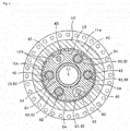
- Fig. 2 is a vertical view cut along the line II-II in Fig. 1 .
- a crankshaft through hole 42 into which the eccentric body 52 is to be inserted is formed at the external gear 40.
- the crankshaft through hole 42 is extended parallel to the axial direction.
- a crankshaft bearing 54 is located between the eccentric body 52 and the crankshaft through hole 42.
- the crankshaft bearing 54 is a needle roller bearing.
- a pillar through hole 43 through which the pillar 63 of the aforementioned carrier 60 is to be extended is also formed at the external gear 40.
- the number of the external teeth 41 provided at the external gear 40 is smaller than the number of the internal teeth 12 on the inner circumference of the case 10 by one or more. Therefore, engagement of the external teeth 41 and the internal teeth 12 deviates with rotation of the crankshaft 50, and the external gear 40 oscillates (rocks) and rotates eccentrically.
- crankshaft through hole 42 is formed in a circular shape, while the pillar through hole 43 is formed in a trapezoidal shape having round corners. That is, the crankshaft through hole 42 and the pillar through hole 43 have different shapes.
- the pillar through hole 43 is not limited to the aforementioned trapezoidal shape, but is formed in a shape which does not interfere with the pillar 63 when the external gear 40 oscillates and rotates eccentrically.
- crankshafts 50 are provided around the central axis L1 in this embodiment. Accordingly, four first end part through holes 71 are formed at the first holding part 61 of the carrier 60, and four second end part through holes 72 are formed at the second holding part 62. Moreover, the spur gear 53 is fixed by each crankshaft 50, so that four spur gears 53 are respectively arranged around the input gear 20 so as to engage with the input gear 20. Moreover, four crankshaft through holes 42 are formed at the external gear 40.
- the carrier 60 has two pillars 63, and a plurality of crankshafts 50 are arranged between the pillars 63 in a radial direction around the central axis L1 of the output shaft 100, i.e., the central axis of the internal teeth 12 of the case 10. More specifically, the two pillars 63 are formed to be separated from each other by 180° in the circumferential direction around the central axis L1 and face each other across the central axis L1. In addition, two (the same plural number of) crankshafts 50 are arranged in each of two areas between the two pillars 63 in the circumferential direction.
- adjacent pillar 63 and crankshaft 50 are spaced from each other by 60° in the circumferential direction around the central axis L1, and two adjacent crankshafts 50 are spaced from each other by 60° in the circumferential direction around the central axis L1. That is, six members composed of two pillars 63 and four crankshafts 50 are arranged at equal intervals in the circumferential direction in this embodiment.
- two pillar through holes 43 in the external gear 40 are formed to be spaced from each other by 180° in the circumferential direction around the central axis L1 and face each other across the central axis L1.
- two (the same plural number of) crankshaft through holes 42 are formed in each of two areas between the two pillar through holes 43 in the circumferential direction of the external gear 40.
- the number of the pillars 63 is decreased with respect to the number of the crankshafts 50 in comparison with a case where the number of crankshafts and the number of pillars are equal to each other. This simplifies the structure of the carrier 60 and, therefore, manufacturing of the reduction gear device 1 can be proceeded advantageously.
- the probability of generation of a so-called mold cavity in the carrier 60 during formation by molding becomes high in a case where the structure of the carrier 60 is complex. That is, the probability of occurrence of variation in the density of the carrier 60 becomes high.
- the reduction gear device 1 according to this embodiment it is possible with the reduction gear device 1 according to this embodiment to simplify the structure of the carrier 60 and, therefore, generation of a mold cavity can be suppressed even when the carrier 60 is formed by molding. Accordingly, there is an advantage that the product quality can be increased. Moreover, there is another advantage that the mold can be simplified and, therefore, the manufacturing cost can be lowered.
- the reduction gear device 1 it is possible with the reduction gear device 1 according to this embodiment to cause increase in the contact area between the crankshafts 50 and the external gear 40 by increasing the number of the crankshafts 50 with respect to the number of the pillars 63 and, therefore, power to be transmitted from the crankshafts 50 to the external gear 40 can be increased.
- the number of the crankshaft through holes 42 in the external gear 40 is increased with respect to the number of the pillar through holes 43 in comparison with a case where the number of crankshaft through holes and the number of pillar through holes are equal to each other. This can cause increase in the contact area between the crankshafts 50 and the external gear 40 and, therefore, power to be transmitted from the crankshafts 50 to the external gear 40 is increased.
- needle roller bearings (73, 74) are respectively arranged between the first holding part 61 of the carrier 60 and the one end part of the crankshaft 50, and between the second holding part 62 and the other end part of the crankshaft 50 in the reduction gear device 1 according to this embodiment. It is possible with such a structure to reduce power in the thrust direction to be transmitted from a crankshaft 50 to the carrier 60 in comparison with a case where a tapered roller bearing is used for holding the crankshaft 50. As a result, the stiffness of the carrier 60 at a level which does not cause a problem in actual use is ensured even when the number of pillars 63 is decreased. This makes it possible to prevent a functional problem from being caused by simplification of the carrier 60.
- two pillar through holes 43 are arranged in the external gear 40 so as to be spaced from each other in the circumferential direction of the gear, and the same plural number of, or more specifically two, crankshaft through holes 42 are arranged in each of two areas between the two pillar through holes 43 in the circumferential direction in this embodiment. That is, the same plural number of, or more specifically two, crankshafts 50 are arranged in each of two areas between the two pillars 63 in the circumferential direction in the reduction gear device 1. It is possible with such a structure to uniformize power to be applied to the external gear 40 in one and the other of areas between the two pillar through holes 43. This makes it possible to improve the durability of the external gear 40.
- the present invention is not limited to the above embodiment.
- two pillars 63 are arranged and four crankshafts 50 are arranged in the reduction gear device 1 in the above embodiment
- the number of the pillars 63 and the number of the crankshafts 50 may be other aspects, for example.
- Three crankshafts 50 may be arranged, for example, in each of two areas between two pillars 63 in the circumferential direction.
- three pillars 63 may be arranged in the reduction gear device 1, and a plurality of crankshafts 50 may be arranged between adjacent pillars 63.
- one pillar 63 may be located in the reduction gear device 1, and a plurality of crankshafts 50 may be arranged between the pillar 63 in the circumferential direction.
Landscapes
- Engineering & Computer Science (AREA)
- General Engineering & Computer Science (AREA)
- Mechanical Engineering (AREA)
- Retarders (AREA)
- Rolling Contact Bearings (AREA)
Abstract
Description
- The present invention relates to a reduction gear device wherein a gear having external teeth is located in a case having internal teeth on the inner circumference side and the gear rotates with the external teeth thereof engaging with the internal teeth of the case, and a gear used for the reduction gear device.
- An eccentric oscillation-type reduction gear device is known as a reduction gear device of this sort. Such a reduction gear device is generally provided with: a case having internal teeth on the inner circumference side; a gear (which will be hereinafter referred to as an external gear) having external teeth to engage with the internal teeth; a crankshaft which is inserted into a through hole formed at the external gear and rotates to oscillate the external gear; and a carrier configured to hold the external gear via the crankshaft. The crankshaft is rotatably held by the carrier, and is provided with an eccentric body. The eccentric body is inserted into the through hole of the external gear. This allows the carrier to hold the external gear via the crankshaft.
- Moreover, the carrier has: a first holding part configured to rotatably hold one end part of the crankshaft; a second holding part configured to rotatably hold the other end part of the crankshaft; and a pillar configured to couple the first holding part and the second holding part with each other in the axial direction, and the aforementioned external gear is located between the first holding part and the second holding part. At the external gear, a through hole through which the pillar is extended is formed in addition to the through hole into which the eccentric body of the crankshaft is inserted.
- When input from outside causes the crankshaft in such a reduction gear device to rotate on the central axis thereof, the eccentric body oscillates the external gear, and the external gear rotates with the external teeth thereof engaging with the internal teeth of the case. This allows the crankshaft to revolve while rotating on the own axis, and the revolving motion causes the carrier to rotate (see
Patent Document 1, for example). - Patent Document 1:
JP 2013-7459 A - In the aforementioned reduction gear device, crankshafts and pillars of the carrier are generally arranged alternately in the circumferential direction, and the number of the crankshafts and the number of the pillars are equal to each other as illustrated in
Patent Document 1. Such a structure however may possibly complicate the entire structure of the carrier, since the number of the pillars which are formed at the carrier and respectively have a relatively complex structure is equal to the number of the crankshafts. Accordingly, there is room for improvement in simplification of the carrier. - The present invention has been made in view of such circumstances, and the object thereof is to provide a reduction gear device with which the structure of a carrier can be simplified and which can be manufactured advantageously; and a gear used for the reduction gear device.
- The present invention is a reduction gear device including: a case having internal teeth on an inner circumference side; a gear having external teeth to engage with the internal teeth; crankshafts configured to oscillate the gear; and a carrier having a first holding part configured to rotatably hold one end parts of the crankshafts, a second holding part configured to rotatably hold the other end parts of the crankshafts, and one or more pillar(s) configured to couple the first holding part and the second holding part with each other, wherein the crankshafts are arranged between the one or more pillar(s) in a circumferential direction around a central axis of the internal teeth of the case.
- With a reduction gear device according to the present invention wherein a plurality of crankshafts are arranged between pillars, the number of the pillars is decreased with respect to the number of the crankshafts in comparison with a case where the number of crankshafts and the number of pillars are equal to each other. This can simplify the structure of the carrier. Moreover, increase in the number of the crankshafts with respect to the number of the pillars causes increase in the contact area between the crankshafts and the gear and, furthermore, increase in power to be transmitted from the crankshafts to the gear.
- In the reduction gear device, needle roller bearings may be respectively arranged between the first holding part and the one end parts of the crankshafts, and between the second holding part and the other end parts of the crankshaft.
- It is possible with such a structure to reduce power in the thrust direction to be transmitted from the crankshafts to the carrier in comparison with a case where a tapered roller bearing is used for holding a crankshaft.
- Moreover, the present invention is a gear for a reduction gear device, which has external teeth to engage with internal teeth of a case having the internal teeth on an inner circumference side and is held by a carrier having a first holding part configured to rotatably hold one end parts of crankshafts, a second holding part configured to rotatably hold the other end parts of the crankshafts, and one or more pillar(s) configured to couple the first holding part and the second holding part with each other via the crankshafts and rocked by the crankshafts, and the gear includes: crankshaft through holes through which the crankshafts are extended; and one or more pillar through hole(s) through which the one or more pillar(s) are extended, wherein the crankshafts through holes are arranged between the one or more pillar through hole(s) in a circumferential direction of the gear.
- It is possible with a gear according to the present invention to construct a reduction gear device with which the structure of a carrier can be simplified. Moreover, the number of crankshaft through holes is increased with respect to the number of pillar through holes in comparison with a case where the number of crankshaft through holes and the number of pillar through holes are equal to each other. This causes increase in the contact area between the crankshafts and the gear and, furthermore, increase in power to be transmitted from the crankshafts to the gear.
- Moreover, in the gear, two pillar through holes may be arranged to be spaced from each other in the circumferential direction of the gear, and the same plural number of crankshaft through holes may be arranged in each of two areas between the two pillar through holes in the circumferential direction of the gear.
- It is possible with such a structure to uniformize power to be applied to the gear on one and the other of areas between two pillar through holes and, therefore, the durability can be improved.
- It is possible with the present invention to provide a reduction gear device with which the structure of a carrier can be simplified and which can be manufactured advantageously.
-
-
Fig. 1 is a sectional view of a reduction gear device according to one embodiment of the present invention. -
Fig. 2 is a sectional view cut along the line II-II inFig. 1 . - The following description will explain one embodiment of the present invention with reference to the drawings.
- A
reduction gear device 1 according to this embodiment illustrated inFig. 1 is an eccentric oscillation-type reduction gear device (an eccentric rocking-type reduction gear device). Thereduction gear device 1 is suitable as a reduction gear device to be used for a yaw drive assembly, which performs yaw drive so as to rotate a nacelle against a tower in a windmill, or a pitch drive assembly, which performs pitch drive so as to rotate the shaft part of a blade against a hub on the nacelle side, for example. It is to be noted that thereduction gear device 1 can be used not only for a windmill but also for various industrial machines, construction machines or the like. - As illustrated in
Fig. 1 , thereduction gear device 1 according to this embodiment is provided with: acase 10; aninput gear 20 and areduction gear unit 30 housed in thecase 10; and anoutput shaft 100 which has one end part coupled with thereduction gear unit 30 and the other end part projected from thecase 10. Thecase 10 is formed in a cylindrical shape and hasinternal teeth 12 on the inner circumference side (inner circumferential surface). Thereduction gear unit 30 has: anexternal gear 40 having external teeth 41 to engage with theinternal teeth 12 of thecase 10; acrankshaft 50 configured to oscillate (rock) theexternal gear 40; and acarrier 60 configured to rotatably hold thecrankshaft 50 and hold theexternal gear 40 via thecrankshaft 50. - In the
reduction gear device 1, rotation inputted from a motor (not illustrated) through theinput gear 20 is deceased in speed by thereduction gear unit 30 and then outputted from theoutput shaft 100. The other end part of theoutput shaft 100 projected from thecase 10 is provided with adriving gear 101. Rotation inputted from theinput gear 20 is decreased in speed and then transmitted to a driven gear (not illustrated) engaging with thedriving gear 101. - Denoted at L1 in the figure is the central axis of the
output shaft 100. The central axis of the inner circumferential surface of thecase 10 provided with theinternal teeth 12 is positioned coaxially with the central axis L1. When a direction is referred to simply as "axial direction" in the following description, this means a direction which extends on the central axis L1, or a direction parallel to the central axis L1. Moreover, a direction orthogonal to the central axis L1 will be referred to as a radial direction, and a direction around the central axis L1 will be referred to as a circumferential direction. - The
case 10 has: amain case part 11a which is formed in a cylindrical shape having both end parts that are open; and asub case part 11b which is mounted on an open portion on one end part of themain case part 11a. Themain case part 11a and thesub case part 11b are coupled with each other by fastening edge parts of the respective case parts with each other with bolts (not illustrated). Regarding themain case part 11a, theoutput shaft 100 is projected from the other end part opposite to the one end part where thesub case part 11b is mounted. Anannular wall part 11c protruded to inside in the radial direction is formed on the inner circumferential surface of a middle portion between the one end part and the other end part of themain case part 11a. - The
main case part 11a has: aninput side portion 111 which is positioned on the one end part side with respect to theannular wall part 11c, i.e., thesub case part 11b side; and anoutput side portion 112 which is positioned on the other end part side with respect to theannular wall part 11c, i.e., a side where theoutput shaft 100 is projected. Among these members, thereduction gear unit 30 is housed in theinput side portion 111, and the aforementionedinternal teeth 12 are provided on the inner circumferential surface of theinput side portion 111. - The
internal teeth 12 are constituted of a plurality ofinternal tooth pins 12A which are respectively formed in a pin shape. Theinternal tooth pins 12A are fitted in and attached to a plurality ofpin grooves 13 which are formed in line in the circumferential direction over the entire area of the inner circumferential surface of theinput side portion 111 of themain case part 11a. Theinternal tooth pins 12A are arranged in a manner such that the longitudinal direction thereof is positioned parallel to the central axis L1 direction. Theinternal tooth pins 12A are arranged on the inner circumferential surface of theinput side portion 111 of themain case part 11a at equal intervals along the circumferential direction, and are configured to engage with the external teeth 41 of the aforementionedexternal gear 40. - An annular first bearing
housing groove 14 recessed from theinput side portion 111 side to theoutput side portion 112 side is formed at theannular wall part 11c of themain case part 11a. A first bearing 15 is inserted into the first bearinghousing groove 14. The first bearing 15 illustrated in the figure is a tapered roller bearing. Thefirst bearing 15 has an outer ring which is brought into contact with or close to the bottom face of the first bearinghousing groove 14 in the axial direction and brought into contact with or close to a side face of the first bearinghousing groove 14 in the radial direction. This allows thefirst bearing 15 to be attached to the first bearinghousing groove 14. - Moreover, an annular second bearing
housing groove 16 recessed from theoutput side portion 112 side to theinput side portion 111 side is formed at the other end part (outer end part) of theoutput side portion 112. Asecond bearing 17 is inserted into the secondbearing housing groove 16. Thesecond bearing 17 illustrated in the figure is a tapered roller bearing. Thesecond bearing 17 has an outer ring which is brought into contact with or close to the bottom face of the secondbearing housing groove 16 in the axial direction and brought into contact with or close to a side face of the secondbearing housing groove 16 in the radial direction. This allows thesecond bearing 17 to be attached to the secondbearing housing groove 16. - The
output shaft 100 is inserted into the inner circumference side of the inner ring of thefirst bearing 15 and the inner circumference side of the inner ring of thesecond bearing 17. This allows theoutput shaft 100 to be rotatably held by thecase 10. Theoutput shaft 100 is projected from thefirst bearing 15 to theinput side portion 111 of themain case part 11a. Theoutput shaft 100 is coupled with thereduction gear unit 30 at a portion thereof projected to theinput side portion 111. Aspline part 102 is formed at the outer circumferential surface of a portion of theoutput shaft 100 projected to theinput side portion 111. Thecarrier 60 of thereduction gear unit 30 is fitted in thespline part 102. This allows theoutput shaft 100 to be coupled with thereduction gear unit 30. Details of such a structure will be described later. - The
aforementioned input gear 20 is located on thesub case part 11b side of thecase 10. A motor (illustration is omitted) is attached to thesub case part 11b, so that rotation of the motor is transmitted to theinput gear 20. Theinput gear 20 is a spur gear, and is located in a manner such that the central axis thereof is positioned on the central axis L1 of theoutput shaft 100. Theinput gear 20 engages with aspur gear 53, which is provided at one end part of thecrankshaft 50 and will be described later, so that rotation of theinput gear 20 is transmitted to thecrankshaft 50. - The
reduction gear unit 30 has theexternal gear 40, thecrankshaft 50 and thecarrier 60 as described above. Among these members, thecarrier 60 has: a first holdingpart 61 configured to rotatably hold one end part of the crankshaft 50 (end part on theinput gear 20 side); a second holdingpart 62 configured to rotatably hold the other end part of the crankshaft 50 (end part on a side where theoutput shaft 100 is projected); a pillar 63 (seeFig. 2 ) configured to couple the first holdingpart 61 and the second holdingpart 62 with each other; and acylindrical coupling part 64 to be used for coupling thecarrier 60 with theoutput shaft 100. It is to be noted that thepillar 63 is drawn with long dashed double-short dashed lines inFig. 1 for convenience of explanation. - The first holding
part 61 and the second holdingpart 62 are respectively formed in an annular shape, and are spaced from and face each other in the axial direction. Thepillar 63 is provided to lie between a substantially middle area of the first holdingpart 61 in the radial direction and a substantially middle area of the second holdingpart 62 in the radial direction, so as to couple the first holdingpart 61 and the second holdingpart 62 with each other. Moreover, thecylindrical coupling part 64 is provided to lie between an inner circumferential edge of the first holdingpart 61 and an inner circumferential edge of the second holdingpart 62. Thecylindrical coupling part 64 is formed in a cylindrical shape, and has aspline part 65 formed on the inner circumferential surface thereof. Thespline part 102 of theoutput shaft 100 is inserted into and fitted in thespline part 65, so that theoutput shaft 100 and thereduction gear unit 30 are coupled with each other. - A first end part through
hole 71 is formed at the first holdingpart 61. One end part of thecrankshaft 50 is rotatably held by the first end part throughhole 71 via afirst crankshaft bearing 73. The first crankshaft bearing 73 illustrated in the figure is a needle roller bearing. That is, theneedle roller bearing 73 is located between the first end part throughhole 71 of the first holdingpart 61 and one end part of thecrankshaft 50 in this embodiment. Moreover, a second end part throughhole 72 is formed at the second holdingpart 62. The other end part of thecrankshaft 50 is rotatably held by the second end part throughhole 72 via a second crankshaft bearing 74. The second crankshaft bearing 74 illustrated in the figure is a needle roller bearing. That is, theneedle roller bearing 74 is located between the second end part throughhole 72 of the second holdingpart 62 and the other end part of thecrankshaft 50 in this embodiment. It is to be noted that the first crankshaft bearing 73 and the second crankshaft bearing 74 functioning as needle roller bearings are respectively constructed by holding a cylindrical rolling member between an outer race and an inner race, though the bearings are drawn schematically in the figure. - Next, the
crankshaft 50 in this embodiment has ashaft body 51, an eccentric body 52 (seeFig. 2 ) and theaforementioned spur gear 53. Among these members, one end part of theshaft body 51 is rotatably held by the first end part throughhole 71 via the first crankshaft bearing 73, while the other end part of theshaft body 51 is rotatably held by the second end part throughhole 72 via the second crankshaft bearing 74. Moreover, the one end part of theshaft body 51 is projected from the first end part throughhole 71 to thesub case part 11b side, and thespur gear 53 is fixed to a portion of the one end part of theshaft body 51 projected from the first end part throughhole 71. - The eccentric body 52 is located between the first holding
part 61 and the second holdingpart 62 of thecarrier 60 with thecrankshaft 50 being held by thecarrier 60. Moreover, theexternal gear 40 is located between the first holdingpart 61 and the second holdingpart 62. Here, the eccentric body 52 is inserted into theexternal gear 40. -
Fig. 2 is a vertical view cut along the line II-II inFig. 1 . A crankshaft throughhole 42 into which the eccentric body 52 is to be inserted is formed at theexternal gear 40. The crankshaft throughhole 42 is extended parallel to the axial direction. As illustrated inFig. 2 , acrankshaft bearing 54 is located between the eccentric body 52 and the crankshaft throughhole 42. Thecrankshaft bearing 54 is a needle roller bearing. Moreover, a pillar throughhole 43 through which thepillar 63 of theaforementioned carrier 60 is to be extended is also formed at theexternal gear 40. - The number of the external teeth 41 provided at the
external gear 40 is smaller than the number of theinternal teeth 12 on the inner circumference of thecase 10 by one or more. Therefore, engagement of the external teeth 41 and theinternal teeth 12 deviates with rotation of thecrankshaft 50, and theexternal gear 40 oscillates (rocks) and rotates eccentrically. - Regarding the
external gear 40, it is to be noted that the crankshaft throughhole 42 is formed in a circular shape, while the pillar throughhole 43 is formed in a trapezoidal shape having round corners. That is, the crankshaft throughhole 42 and the pillar throughhole 43 have different shapes. The pillar throughhole 43 is not limited to the aforementioned trapezoidal shape, but is formed in a shape which does not interfere with thepillar 63 when theexternal gear 40 oscillates and rotates eccentrically. - As illustrated in
Fig. 2 , fourcrankshafts 50 are provided around the central axis L1 in this embodiment. Accordingly, four first end part throughholes 71 are formed at the first holdingpart 61 of thecarrier 60, and four second end part throughholes 72 are formed at the second holdingpart 62. Moreover, thespur gear 53 is fixed by eachcrankshaft 50, so that fourspur gears 53 are respectively arranged around theinput gear 20 so as to engage with theinput gear 20. Moreover, four crankshaft throughholes 42 are formed at theexternal gear 40. - Now, the arrangement configuration of the
crankshafts 50 and thepillars 63 of thecarrier 60 according to this embodiment will be described in detail with reference toFig. 2 . In this embodiment, thecarrier 60 has twopillars 63, and a plurality ofcrankshafts 50 are arranged between thepillars 63 in a radial direction around the central axis L1 of theoutput shaft 100, i.e., the central axis of theinternal teeth 12 of thecase 10. More specifically, the twopillars 63 are formed to be separated from each other by 180° in the circumferential direction around the central axis L1 and face each other across the central axis L1. In addition, two (the same plural number of)crankshafts 50 are arranged in each of two areas between the twopillars 63 in the circumferential direction. - In the illustrated example,
adjacent pillar 63 andcrankshaft 50 are spaced from each other by 60° in the circumferential direction around the central axis L1, and twoadjacent crankshafts 50 are spaced from each other by 60° in the circumferential direction around the central axis L1. That is, six members composed of twopillars 63 and fourcrankshafts 50 are arranged at equal intervals in the circumferential direction in this embodiment. - Similarly, two pillar through
holes 43 in theexternal gear 40 are formed to be spaced from each other by 180° in the circumferential direction around the central axis L1 and face each other across the central axis L1. In addition, two (the same plural number of) crankshaft throughholes 42 are formed in each of two areas between the two pillar throughholes 43 in the circumferential direction of theexternal gear 40. - Next, the function of this embodiment will be described.
- When a motor which is not illustrated in the figure causes the
input gear 20 in the aforementionedreduction gear device 1 to rotate, the respective spur gears 53 engaging with theinput gear 20 are rotated, and therespective crankshafts 50 are rotated. With such rotation, theexternal gear 40 rotates eccentrically to oscillate while causing deviation of engagement with theinternal teeth 12. With such eccentric rotation of theexternal gear 40, therespective crankshafts 50 move in revolving motion centering on the central axis L1 while rotating on the own axis. Such revolving motion of thecrankshaft 50 causes thecarrier 60 configured to hold thecrankshafts 50 to rotate. This allows theoutput shaft 100 coupled with thecarrier 60 in spline coupling to rotate, and then torque can be transmitted from thedriving gear 101. - With the
reduction gear device 1 according to this embodiment wherein a plurality ofcrankshafts 50 are arranged betweenpillars 63 of thecarrier 60, the number of thepillars 63 is decreased with respect to the number of thecrankshafts 50 in comparison with a case where the number of crankshafts and the number of pillars are equal to each other. This simplifies the structure of thecarrier 60 and, therefore, manufacturing of thereduction gear device 1 can be proceeded advantageously. - That is, the probability of generation of a so-called mold cavity in the
carrier 60 during formation by molding becomes high in a case where the structure of thecarrier 60 is complex. That is, the probability of occurrence of variation in the density of thecarrier 60 becomes high. On the contrary, it is possible with thereduction gear device 1 according to this embodiment to simplify the structure of thecarrier 60 and, therefore, generation of a mold cavity can be suppressed even when thecarrier 60 is formed by molding. Accordingly, there is an advantage that the product quality can be increased. Moreover, there is another advantage that the mold can be simplified and, therefore, the manufacturing cost can be lowered. - On the other hand, in a case where
carrier 60 is formed by forging and the structure of thecarrier 60 is complex, a complex special tool is required for formation by forging and, therefore, the manufacturing cost is increased. On the contrary, it is possible with thereduction gear device 1 according to this embodiment to simplify the structure of thecarrier 60 and, therefore, complication of a special tool can be suppressed even when thecarrier 60 is formed by forging. Accordingly, there is an advantage that the manufacturing cost can be lowered. - Moreover, it is possible with the
reduction gear device 1 according to this embodiment to cause increase in the contact area between thecrankshafts 50 and theexternal gear 40 by increasing the number of thecrankshafts 50 with respect to the number of thepillars 63 and, therefore, power to be transmitted from thecrankshafts 50 to theexternal gear 40 can be increased. In other words, the number of the crankshaft throughholes 42 in theexternal gear 40 is increased with respect to the number of the pillar throughholes 43 in comparison with a case where the number of crankshaft through holes and the number of pillar through holes are equal to each other. This can cause increase in the contact area between thecrankshafts 50 and theexternal gear 40 and, therefore, power to be transmitted from thecrankshafts 50 to theexternal gear 40 is increased. - Moreover, needle roller bearings (73, 74) are respectively arranged between the first holding
part 61 of thecarrier 60 and the one end part of thecrankshaft 50, and between the second holdingpart 62 and the other end part of thecrankshaft 50 in thereduction gear device 1 according to this embodiment. It is possible with such a structure to reduce power in the thrust direction to be transmitted from acrankshaft 50 to thecarrier 60 in comparison with a case where a tapered roller bearing is used for holding thecrankshaft 50. As a result, the stiffness of thecarrier 60 at a level which does not cause a problem in actual use is ensured even when the number ofpillars 63 is decreased. This makes it possible to prevent a functional problem from being caused by simplification of thecarrier 60. - Furthermore, two pillar through
holes 43 are arranged in theexternal gear 40 so as to be spaced from each other in the circumferential direction of the gear, and the same plural number of, or more specifically two, crankshaft throughholes 42 are arranged in each of two areas between the two pillar throughholes 43 in the circumferential direction in this embodiment. That is, the same plural number of, or more specifically two,crankshafts 50 are arranged in each of two areas between the twopillars 63 in the circumferential direction in thereduction gear device 1. It is possible with such a structure to uniformize power to be applied to theexternal gear 40 in one and the other of areas between the two pillar through holes 43. This makes it possible to improve the durability of theexternal gear 40. - Although one embodiment of the present invention has been described above, the present invention is not limited to the above embodiment. Although two
pillars 63 are arranged and fourcrankshafts 50 are arranged in thereduction gear device 1 in the above embodiment, the number of thepillars 63 and the number of thecrankshafts 50 may be other aspects, for example. Threecrankshafts 50 may be arranged, for example, in each of two areas between twopillars 63 in the circumferential direction. Moreover, threepillars 63 may be arranged in thereduction gear device 1, and a plurality ofcrankshafts 50 may be arranged betweenadjacent pillars 63. Moreover, onepillar 63 may be located in thereduction gear device 1, and a plurality ofcrankshafts 50 may be arranged between thepillar 63 in the circumferential direction. -
- 1
- Reduction Gear Device
- 10
- Case
- 12
- Internal Tooth
- 20
- Input Gear
- 30
- Reduction Gear Unit
- 40
- External Gear
- 41
- External Tooth
- 42
- Crankshaft Through Hole
- 43
- Pillar Through Hole
- 50
- Crankshaft
- 53
- Spur Gear
- 60
- Carrier
- 61
- First Holding Part
- 62
- Second Holding Part
- 63
- Pillar
- 71
- First End Part Through Hole
- 72
- Second End Part Through Hole
- 73
- First Crank Bearing
- 74
- Second Crank Bearing
- L1
- Central Axis
Claims (4)
- A reduction gear device comprising:a case having internal teeth on an inner circumference side;a gear having external teeth to engage with the internal teeth;crankshafts configured to oscillate the gear; anda carrier having a first holding part configured to rotatably hold one end parts of the crankshafts, a second holding part configured to rotatably hold the other end parts of the crankshafts, and one or more pillar(s) configured to couple the first holding part and the second holding part with each other,wherein the crankshafts are arranged between the one or more pillar(s) in a circumferential direction around a central axis of the internal teeth of the case.
- The reduction gear device according to claim 1, wherein needle roller bearings are respectively arranged between the first holding part and the one end parts of the crankshafts, and between the second holding part and the other end parts of the crankshafts.
- A gear for a reduction gear device, which has external teeth to engage with internal teeth of a case having the internal teeth on an inner circumference side and is held by a carrier having a first holding part configured to rotatably hold one end parts of crankshafts, a second holding part configured to rotatably hold the other end parts of the crankshafts, and one or more pillar(s) configured to couple the first holding part and the second holding part with each other via the crankshafts and oscillated by the crankshafts, comprising:crankshaft through holes through which the crankshafts are extended; andone or more pillar through hole(s) through which the one ore more pillar(s) are extended,wherein the crankshaft through holes are arranged between the one or more pillar through hole(s) in a circumferential direction of the gear.
- The gear for a reduction gear device according to claim 3, wherein
two pillar through holes are arranged to be spaced from each other in the circumferential direction of the gear, and
the same plural number of crankshaft through holes is arranged in each of two areas between the two pillar through holes in the circumferential direction of the gear.
Applications Claiming Priority (1)
| Application Number | Priority Date | Filing Date | Title |
|---|---|---|---|
| JP2015083522A JP6522400B2 (en) | 2015-04-15 | 2015-04-15 | Reduction gear and gear used therefor |
Publications (2)
| Publication Number | Publication Date |
|---|---|
| EP3081828A1 true EP3081828A1 (en) | 2016-10-19 |
| EP3081828B1 EP3081828B1 (en) | 2022-08-17 |
Family
ID=56083882
Family Applications (1)
| Application Number | Title | Priority Date | Filing Date |
|---|---|---|---|
| EP16163672.5A Active EP3081828B1 (en) | 2015-04-15 | 2016-04-04 | Reduction gear device |
Country Status (3)
| Country | Link |
|---|---|
| EP (1) | EP3081828B1 (en) |
| JP (1) | JP6522400B2 (en) |
| CN (1) | CN106051064B (en) |
Cited By (1)
| Publication number | Priority date | Publication date | Assignee | Title |
|---|---|---|---|---|
| EP3483473A1 (en) * | 2017-11-14 | 2019-05-15 | Kimex Group s.r.o. | Gearbox |
Families Citing this family (4)
| Publication number | Priority date | Publication date | Assignee | Title |
|---|---|---|---|---|
| CN112368491B (en) * | 2018-06-28 | 2024-08-16 | 住友重机械工业株式会社 | Speed reducer |
| JP7316828B2 (en) * | 2019-04-15 | 2023-07-28 | ナブテスコ株式会社 | Decelerator |
| JP2021067317A (en) * | 2019-10-23 | 2021-04-30 | ナブテスコ株式会社 | Speed reducer |
| JP7530796B2 (en) | 2020-10-05 | 2024-08-08 | ナブテスコ株式会社 | Reducer and eccentric gear of reducer |
Citations (4)
| Publication number | Priority date | Publication date | Assignee | Title |
|---|---|---|---|---|
| EP1296084A2 (en) * | 2001-09-13 | 2003-03-26 | Teijin Seiki Co., Ltd. | Eccentric oscillating-type speed reducer |
| EP1767815A2 (en) * | 2005-09-26 | 2007-03-28 | Nabtesco Corporation | Speed reducer, production method for speed reducer, roller bearing, crankshaft and production method for crank shaft |
| WO2009081451A1 (en) * | 2007-12-21 | 2009-07-02 | Nabtesco Corporation | Eccentric reduction gear |
| DE102012009837A1 (en) * | 2011-06-24 | 2012-12-27 | Sumitomo Heavy Industries, Ltd. | Oscillating internal meshing type rotational speed reduction gear for conveying rotary motion with variable gear ratio, has external toothed gear and internal toothed gear, with which external toothed gear is engaged from inside |
Family Cites Families (4)
| Publication number | Priority date | Publication date | Assignee | Title |
|---|---|---|---|---|
| CN101263319B (en) * | 2005-09-13 | 2013-07-10 | 纳博特斯克株式会社 | Eccentrically rocking type reduction gear |
| JP4749814B2 (en) * | 2005-09-26 | 2011-08-17 | ナブテスコ株式会社 | Differential oscillating speed reducer |
| JP5868724B2 (en) * | 2012-02-23 | 2016-02-24 | 住友重機械工業株式会社 | Reducer, industrial machine, and method of incorporating reducer into industrial machine |
| JP6124583B2 (en) * | 2012-12-19 | 2017-05-10 | ナブテスコ株式会社 | Eccentric oscillating gear unit |
-
2015
- 2015-04-15 JP JP2015083522A patent/JP6522400B2/en not_active Expired - Fee Related
-
2016
- 2016-04-04 EP EP16163672.5A patent/EP3081828B1/en active Active
- 2016-04-08 CN CN201610218856.5A patent/CN106051064B/en not_active Expired - Fee Related
Patent Citations (5)
| Publication number | Priority date | Publication date | Assignee | Title |
|---|---|---|---|---|
| EP1296084A2 (en) * | 2001-09-13 | 2003-03-26 | Teijin Seiki Co., Ltd. | Eccentric oscillating-type speed reducer |
| EP1767815A2 (en) * | 2005-09-26 | 2007-03-28 | Nabtesco Corporation | Speed reducer, production method for speed reducer, roller bearing, crankshaft and production method for crank shaft |
| WO2009081451A1 (en) * | 2007-12-21 | 2009-07-02 | Nabtesco Corporation | Eccentric reduction gear |
| DE102012009837A1 (en) * | 2011-06-24 | 2012-12-27 | Sumitomo Heavy Industries, Ltd. | Oscillating internal meshing type rotational speed reduction gear for conveying rotary motion with variable gear ratio, has external toothed gear and internal toothed gear, with which external toothed gear is engaged from inside |
| JP2013007459A (en) | 2011-06-24 | 2013-01-10 | Sumitomo Heavy Ind Ltd | Rocking inner gearing type reduction gear |
Cited By (1)
| Publication number | Priority date | Publication date | Assignee | Title |
|---|---|---|---|---|
| EP3483473A1 (en) * | 2017-11-14 | 2019-05-15 | Kimex Group s.r.o. | Gearbox |
Also Published As
| Publication number | Publication date |
|---|---|
| JP6522400B2 (en) | 2019-05-29 |
| JP2016205421A (en) | 2016-12-08 |
| EP3081828B1 (en) | 2022-08-17 |
| CN106051064B (en) | 2020-07-03 |
| CN106051064A (en) | 2016-10-26 |
Similar Documents
| Publication | Publication Date | Title |
|---|---|---|
| EP3081828B1 (en) | Reduction gear device | |
| JP5088970B2 (en) | Eccentric reducer | |
| US8568263B2 (en) | Gear transmission | |
| EP2988020B1 (en) | Reduction gear | |
| CN106402282A (en) | Eccentric oscillating gear device and method for manufacturing same | |
| JP5069650B2 (en) | Eccentric reducer | |
| EP2730804B1 (en) | Epicyclic reduction gear | |
| US8337355B2 (en) | Eccentric speed reducer | |
| JP2011021659A (en) | Eccentric reduction gear | |
| JP5123055B2 (en) | Eccentric reducer | |
| JP2008267491A (en) | Planetary gear reducer | |
| JP2016142370A (en) | Bending gear system | |
| JP5069617B2 (en) | Eccentric reducer | |
| JP2009287692A (en) | Eccentric type reduction gear and its pin groove machining method | |
| JP5727334B2 (en) | Planetary gear reducer | |
| JP6453135B2 (en) | Eccentric rocking gear device | |
| JP6580402B2 (en) | Windmill drive | |
| EP2933530B1 (en) | Reducer | |
| JP2016200166A (en) | Speed reducer | |
| WO2009081451A1 (en) | Eccentric reduction gear | |
| JP2010025325A (en) | Eccentric reduction gear | |
| JP2014059065A (en) | Oscillation type planetary gear device | |
| JP2013164165A (en) | Oscillation type planetary gear device |
Legal Events
| Date | Code | Title | Description |
|---|---|---|---|
| PUAI | Public reference made under article 153(3) epc to a published international application that has entered the european phase |
Free format text: ORIGINAL CODE: 0009012 |
|
| AK | Designated contracting states |
Kind code of ref document: A1 Designated state(s): AL AT BE BG CH CY CZ DE DK EE ES FI FR GB GR HR HU IE IS IT LI LT LU LV MC MK MT NL NO PL PT RO RS SE SI SK SM TR |
|
| AX | Request for extension of the european patent |
Extension state: BA ME |
|
| STAA | Information on the status of an ep patent application or granted ep patent |
Free format text: STATUS: REQUEST FOR EXAMINATION WAS MADE |
|
| 17P | Request for examination filed |
Effective date: 20170202 |
|
| RBV | Designated contracting states (corrected) |
Designated state(s): AL AT BE BG CH CY CZ DE DK EE ES FI FR GB GR HR HU IE IS IT LI LT LU LV MC MK MT NL NO PL PT RO RS SE SI SK SM TR |
|
| STAA | Information on the status of an ep patent application or granted ep patent |
Free format text: STATUS: EXAMINATION IS IN PROGRESS |
|
| 17Q | First examination report despatched |
Effective date: 20201216 |
|
| GRAP | Despatch of communication of intention to grant a patent |
Free format text: ORIGINAL CODE: EPIDOSNIGR1 |
|
| STAA | Information on the status of an ep patent application or granted ep patent |
Free format text: STATUS: GRANT OF PATENT IS INTENDED |
|
| INTG | Intention to grant announced |
Effective date: 20220225 |
|
| GRAS | Grant fee paid |
Free format text: ORIGINAL CODE: EPIDOSNIGR3 |
|
| GRAA | (expected) grant |
Free format text: ORIGINAL CODE: 0009210 |
|
| STAA | Information on the status of an ep patent application or granted ep patent |
Free format text: STATUS: THE PATENT HAS BEEN GRANTED |
|
| AK | Designated contracting states |
Kind code of ref document: B1 Designated state(s): AL AT BE BG CH CY CZ DE DK EE ES FI FR GB GR HR HU IE IS IT LI LT LU LV MC MK MT NL NO PL PT RO RS SE SI SK SM TR |
|
| REG | Reference to a national code |
Ref country code: CH Ref legal event code: EP |
|
| REG | Reference to a national code |
Ref country code: DE Ref legal event code: R096 Ref document number: 602016074304 Country of ref document: DE |
|
| REG | Reference to a national code |
Ref country code: IE Ref legal event code: FG4D |
|
| REG | Reference to a national code |
Ref country code: AT Ref legal event code: REF Ref document number: 1512390 Country of ref document: AT Kind code of ref document: T Effective date: 20220915 |
|
| REG | Reference to a national code |
Ref country code: NL Ref legal event code: MP Effective date: 20220817 |
|
| REG | Reference to a national code |
Ref country code: LT Ref legal event code: MG9D |
|
| PG25 | Lapsed in a contracting state [announced via postgrant information from national office to epo] |
Ref country code: SE Free format text: LAPSE BECAUSE OF FAILURE TO SUBMIT A TRANSLATION OF THE DESCRIPTION OR TO PAY THE FEE WITHIN THE PRESCRIBED TIME-LIMIT Effective date: 20220817 Ref country code: RS Free format text: LAPSE BECAUSE OF FAILURE TO SUBMIT A TRANSLATION OF THE DESCRIPTION OR TO PAY THE FEE WITHIN THE PRESCRIBED TIME-LIMIT Effective date: 20220817 Ref country code: PT Free format text: LAPSE BECAUSE OF FAILURE TO SUBMIT A TRANSLATION OF THE DESCRIPTION OR TO PAY THE FEE WITHIN THE PRESCRIBED TIME-LIMIT Effective date: 20221219 Ref country code: NO Free format text: LAPSE BECAUSE OF FAILURE TO SUBMIT A TRANSLATION OF THE DESCRIPTION OR TO PAY THE FEE WITHIN THE PRESCRIBED TIME-LIMIT Effective date: 20221117 Ref country code: NL Free format text: LAPSE BECAUSE OF FAILURE TO SUBMIT A TRANSLATION OF THE DESCRIPTION OR TO PAY THE FEE WITHIN THE PRESCRIBED TIME-LIMIT Effective date: 20220817 Ref country code: LV Free format text: LAPSE BECAUSE OF FAILURE TO SUBMIT A TRANSLATION OF THE DESCRIPTION OR TO PAY THE FEE WITHIN THE PRESCRIBED TIME-LIMIT Effective date: 20220817 Ref country code: LT Free format text: LAPSE BECAUSE OF FAILURE TO SUBMIT A TRANSLATION OF THE DESCRIPTION OR TO PAY THE FEE WITHIN THE PRESCRIBED TIME-LIMIT Effective date: 20220817 Ref country code: FI Free format text: LAPSE BECAUSE OF FAILURE TO SUBMIT A TRANSLATION OF THE DESCRIPTION OR TO PAY THE FEE WITHIN THE PRESCRIBED TIME-LIMIT Effective date: 20220817 Ref country code: ES Free format text: LAPSE BECAUSE OF FAILURE TO SUBMIT A TRANSLATION OF THE DESCRIPTION OR TO PAY THE FEE WITHIN THE PRESCRIBED TIME-LIMIT Effective date: 20220817 |
|
| REG | Reference to a national code |
Ref country code: AT Ref legal event code: MK05 Ref document number: 1512390 Country of ref document: AT Kind code of ref document: T Effective date: 20220817 |
|
| PG25 | Lapsed in a contracting state [announced via postgrant information from national office to epo] |
Ref country code: PL Free format text: LAPSE BECAUSE OF FAILURE TO SUBMIT A TRANSLATION OF THE DESCRIPTION OR TO PAY THE FEE WITHIN THE PRESCRIBED TIME-LIMIT Effective date: 20220817 Ref country code: IS Free format text: LAPSE BECAUSE OF FAILURE TO SUBMIT A TRANSLATION OF THE DESCRIPTION OR TO PAY THE FEE WITHIN THE PRESCRIBED TIME-LIMIT Effective date: 20221217 Ref country code: HR Free format text: LAPSE BECAUSE OF FAILURE TO SUBMIT A TRANSLATION OF THE DESCRIPTION OR TO PAY THE FEE WITHIN THE PRESCRIBED TIME-LIMIT Effective date: 20220817 Ref country code: GR Free format text: LAPSE BECAUSE OF FAILURE TO SUBMIT A TRANSLATION OF THE DESCRIPTION OR TO PAY THE FEE WITHIN THE PRESCRIBED TIME-LIMIT Effective date: 20221118 |
|
| PG25 | Lapsed in a contracting state [announced via postgrant information from national office to epo] |
Ref country code: SM Free format text: LAPSE BECAUSE OF FAILURE TO SUBMIT A TRANSLATION OF THE DESCRIPTION OR TO PAY THE FEE WITHIN THE PRESCRIBED TIME-LIMIT Effective date: 20220817 Ref country code: RO Free format text: LAPSE BECAUSE OF FAILURE TO SUBMIT A TRANSLATION OF THE DESCRIPTION OR TO PAY THE FEE WITHIN THE PRESCRIBED TIME-LIMIT Effective date: 20220817 Ref country code: DK Free format text: LAPSE BECAUSE OF FAILURE TO SUBMIT A TRANSLATION OF THE DESCRIPTION OR TO PAY THE FEE WITHIN THE PRESCRIBED TIME-LIMIT Effective date: 20220817 Ref country code: CZ Free format text: LAPSE BECAUSE OF FAILURE TO SUBMIT A TRANSLATION OF THE DESCRIPTION OR TO PAY THE FEE WITHIN THE PRESCRIBED TIME-LIMIT Effective date: 20220817 Ref country code: AT Free format text: LAPSE BECAUSE OF FAILURE TO SUBMIT A TRANSLATION OF THE DESCRIPTION OR TO PAY THE FEE WITHIN THE PRESCRIBED TIME-LIMIT Effective date: 20220817 |
|
| REG | Reference to a national code |
Ref country code: DE Ref legal event code: R097 Ref document number: 602016074304 Country of ref document: DE |
|
| PG25 | Lapsed in a contracting state [announced via postgrant information from national office to epo] |
Ref country code: SK Free format text: LAPSE BECAUSE OF FAILURE TO SUBMIT A TRANSLATION OF THE DESCRIPTION OR TO PAY THE FEE WITHIN THE PRESCRIBED TIME-LIMIT Effective date: 20220817 Ref country code: EE Free format text: LAPSE BECAUSE OF FAILURE TO SUBMIT A TRANSLATION OF THE DESCRIPTION OR TO PAY THE FEE WITHIN THE PRESCRIBED TIME-LIMIT Effective date: 20220817 |
|
| PLBE | No opposition filed within time limit |
Free format text: ORIGINAL CODE: 0009261 |
|
| STAA | Information on the status of an ep patent application or granted ep patent |
Free format text: STATUS: NO OPPOSITION FILED WITHIN TIME LIMIT |
|
| P01 | Opt-out of the competence of the unified patent court (upc) registered |
Effective date: 20230523 |
|
| PG25 | Lapsed in a contracting state [announced via postgrant information from national office to epo] |
Ref country code: AL Free format text: LAPSE BECAUSE OF FAILURE TO SUBMIT A TRANSLATION OF THE DESCRIPTION OR TO PAY THE FEE WITHIN THE PRESCRIBED TIME-LIMIT Effective date: 20220817 |
|
| 26N | No opposition filed |
Effective date: 20230519 |
|
| PG25 | Lapsed in a contracting state [announced via postgrant information from national office to epo] |
Ref country code: SI Free format text: LAPSE BECAUSE OF FAILURE TO SUBMIT A TRANSLATION OF THE DESCRIPTION OR TO PAY THE FEE WITHIN THE PRESCRIBED TIME-LIMIT Effective date: 20220817 |
|
| REG | Reference to a national code |
Ref country code: CH Ref legal event code: PL |
|
| GBPC | Gb: european patent ceased through non-payment of renewal fee |
Effective date: 20230404 |
|
| PG25 | Lapsed in a contracting state [announced via postgrant information from national office to epo] |
Ref country code: LU Free format text: LAPSE BECAUSE OF NON-PAYMENT OF DUE FEES Effective date: 20230404 |
|
| REG | Reference to a national code |
Ref country code: BE Ref legal event code: MM Effective date: 20230430 |
|
| PG25 | Lapsed in a contracting state [announced via postgrant information from national office to epo] |
Ref country code: MC Free format text: LAPSE BECAUSE OF FAILURE TO SUBMIT A TRANSLATION OF THE DESCRIPTION OR TO PAY THE FEE WITHIN THE PRESCRIBED TIME-LIMIT Effective date: 20220817 |
|
| PG25 | Lapsed in a contracting state [announced via postgrant information from national office to epo] |
Ref country code: GB Free format text: LAPSE BECAUSE OF NON-PAYMENT OF DUE FEES Effective date: 20230404 |
|
| PG25 | Lapsed in a contracting state [announced via postgrant information from national office to epo] |
Ref country code: MC Free format text: LAPSE BECAUSE OF FAILURE TO SUBMIT A TRANSLATION OF THE DESCRIPTION OR TO PAY THE FEE WITHIN THE PRESCRIBED TIME-LIMIT Effective date: 20220817 Ref country code: LI Free format text: LAPSE BECAUSE OF NON-PAYMENT OF DUE FEES Effective date: 20230430 Ref country code: FR Free format text: LAPSE BECAUSE OF NON-PAYMENT OF DUE FEES Effective date: 20230430 Ref country code: CH Free format text: LAPSE BECAUSE OF NON-PAYMENT OF DUE FEES Effective date: 20230430 Ref country code: GB Free format text: LAPSE BECAUSE OF NON-PAYMENT OF DUE FEES Effective date: 20230404 |
|
| REG | Reference to a national code |
Ref country code: IE Ref legal event code: MM4A |
|
| PG25 | Lapsed in a contracting state [announced via postgrant information from national office to epo] |
Ref country code: BE Free format text: LAPSE BECAUSE OF NON-PAYMENT OF DUE FEES Effective date: 20230430 |
|
| PG25 | Lapsed in a contracting state [announced via postgrant information from national office to epo] |
Ref country code: IE Free format text: LAPSE BECAUSE OF NON-PAYMENT OF DUE FEES Effective date: 20230404 |
|
| PG25 | Lapsed in a contracting state [announced via postgrant information from national office to epo] |
Ref country code: IE Free format text: LAPSE BECAUSE OF NON-PAYMENT OF DUE FEES Effective date: 20230404 |
|
| PGFP | Annual fee paid to national office [announced via postgrant information from national office to epo] |
Ref country code: DE Payment date: 20240418 Year of fee payment: 9 |
|
| PGFP | Annual fee paid to national office [announced via postgrant information from national office to epo] |
Ref country code: IT Payment date: 20240424 Year of fee payment: 9 |
|
| PG25 | Lapsed in a contracting state [announced via postgrant information from national office to epo] |
Ref country code: BG Free format text: LAPSE BECAUSE OF FAILURE TO SUBMIT A TRANSLATION OF THE DESCRIPTION OR TO PAY THE FEE WITHIN THE PRESCRIBED TIME-LIMIT Effective date: 20220817 |
|
| PG25 | Lapsed in a contracting state [announced via postgrant information from national office to epo] |
Ref country code: BG Free format text: LAPSE BECAUSE OF FAILURE TO SUBMIT A TRANSLATION OF THE DESCRIPTION OR TO PAY THE FEE WITHIN THE PRESCRIBED TIME-LIMIT Effective date: 20220817 |
|
| PG25 | Lapsed in a contracting state [announced via postgrant information from national office to epo] |
Ref country code: CY Free format text: LAPSE BECAUSE OF FAILURE TO SUBMIT A TRANSLATION OF THE DESCRIPTION OR TO PAY THE FEE WITHIN THE PRESCRIBED TIME-LIMIT; INVALID AB INITIO Effective date: 20160404 |
|
| PG25 | Lapsed in a contracting state [announced via postgrant information from national office to epo] |
Ref country code: HU Free format text: LAPSE BECAUSE OF FAILURE TO SUBMIT A TRANSLATION OF THE DESCRIPTION OR TO PAY THE FEE WITHIN THE PRESCRIBED TIME-LIMIT; INVALID AB INITIO Effective date: 20160404 |
|
| REG | Reference to a national code |
Ref country code: DE Ref legal event code: R119 Ref document number: 602016074304 Country of ref document: DE |
|
| PG25 | Lapsed in a contracting state [announced via postgrant information from national office to epo] |
Ref country code: TR Free format text: LAPSE BECAUSE OF FAILURE TO SUBMIT A TRANSLATION OF THE DESCRIPTION OR TO PAY THE FEE WITHIN THE PRESCRIBED TIME-LIMIT Effective date: 20220817 |
|
| PG25 | Lapsed in a contracting state [announced via postgrant information from national office to epo] |
Ref country code: DE Free format text: LAPSE BECAUSE OF NON-PAYMENT OF DUE FEES Effective date: 20251104 |
|
| PG25 | Lapsed in a contracting state [announced via postgrant information from national office to epo] |
Ref country code: IT Free format text: LAPSE BECAUSE OF NON-PAYMENT OF DUE FEES Effective date: 20250404 |