EP3081824A1 - Disconnect shaft for an integrated drive generator (idg) - Google Patents
Disconnect shaft for an integrated drive generator (idg) Download PDFInfo
- Publication number
- EP3081824A1 EP3081824A1 EP16164751.6A EP16164751A EP3081824A1 EP 3081824 A1 EP3081824 A1 EP 3081824A1 EP 16164751 A EP16164751 A EP 16164751A EP 3081824 A1 EP3081824 A1 EP 3081824A1
- Authority
- EP
- European Patent Office
- Prior art keywords
- centimeters
- inches
- teeth
- shaft
- disconnect shaft
- Prior art date
- Legal status (The legal status is an assumption and is not a legal conclusion. Google has not performed a legal analysis and makes no representation as to the accuracy of the status listed.)
- Granted
Links
Images



Classifications
-
- F—MECHANICAL ENGINEERING; LIGHTING; HEATING; WEAPONS; BLASTING
- F16—ENGINEERING ELEMENTS AND UNITS; GENERAL MEASURES FOR PRODUCING AND MAINTAINING EFFECTIVE FUNCTIONING OF MACHINES OR INSTALLATIONS; THERMAL INSULATION IN GENERAL
- F16D—COUPLINGS FOR TRANSMITTING ROTATION; CLUTCHES; BRAKES
- F16D11/00—Clutches in which the members have interengaging parts
- F16D11/14—Clutches in which the members have interengaging parts with clutching members movable only axially
-
- F—MECHANICAL ENGINEERING; LIGHTING; HEATING; WEAPONS; BLASTING
- F16—ENGINEERING ELEMENTS AND UNITS; GENERAL MEASURES FOR PRODUCING AND MAINTAINING EFFECTIVE FUNCTIONING OF MACHINES OR INSTALLATIONS; THERMAL INSULATION IN GENERAL
- F16D—COUPLINGS FOR TRANSMITTING ROTATION; CLUTCHES; BRAKES
- F16D1/00—Couplings for rigidly connecting two coaxial shafts or other movable machine elements
- F16D1/02—Couplings for rigidly connecting two coaxial shafts or other movable machine elements for connecting two abutting shafts or the like
-
- F—MECHANICAL ENGINEERING; LIGHTING; HEATING; WEAPONS; BLASTING
- F16—ENGINEERING ELEMENTS AND UNITS; GENERAL MEASURES FOR PRODUCING AND MAINTAINING EFFECTIVE FUNCTIONING OF MACHINES OR INSTALLATIONS; THERMAL INSULATION IN GENERAL
- F16C—SHAFTS; FLEXIBLE SHAFTS; ELEMENTS OR CRANKSHAFT MECHANISMS; ROTARY BODIES OTHER THAN GEARING ELEMENTS; BEARINGS
- F16C2360/00—Engines or pumps
- F16C2360/23—Gas turbine engines
-
- F—MECHANICAL ENGINEERING; LIGHTING; HEATING; WEAPONS; BLASTING
- F16—ENGINEERING ELEMENTS AND UNITS; GENERAL MEASURES FOR PRODUCING AND MAINTAINING EFFECTIVE FUNCTIONING OF MACHINES OR INSTALLATIONS; THERMAL INSULATION IN GENERAL
- F16C—SHAFTS; FLEXIBLE SHAFTS; ELEMENTS OR CRANKSHAFT MECHANISMS; ROTARY BODIES OTHER THAN GEARING ELEMENTS; BEARINGS
- F16C3/00—Shafts; Axles; Cranks; Eccentrics
- F16C3/02—Shafts; Axles
-
- F—MECHANICAL ENGINEERING; LIGHTING; HEATING; WEAPONS; BLASTING
- F16—ENGINEERING ELEMENTS AND UNITS; GENERAL MEASURES FOR PRODUCING AND MAINTAINING EFFECTIVE FUNCTIONING OF MACHINES OR INSTALLATIONS; THERMAL INSULATION IN GENERAL
- F16D—COUPLINGS FOR TRANSMITTING ROTATION; CLUTCHES; BRAKES
- F16D11/00—Clutches in which the members have interengaging parts
- F16D2011/008—Clutches in which the members have interengaging parts characterised by the form of the teeth forming the inter-engaging parts; Details of shape or structure of these teeth
Definitions
- Exemplary embodiments of this invention generally relate to an integrated drive generator, and more particularly, to a disconnect shaft of an integrated drive generator.
- a typical electrical system utilizes an integrated drive generator (IDG) coupled to each engine to provide a fixed frequency power to the distribution system and loads.
- IDG integrated drive generator
- One type of IDG includes a generator, a hydraulic unit, and a differential assembly arranged in a common housing.
- the differential assembly is operably coupled to a gas turbine engine via an input shaft. The rotational speed of the input shaft varies during the operation of the gas turbine engine.
- the hydraulic unit cooperates with the differential assembly to provide a constant speed to the generator throughout engine operation.
- a disconnect shaft including a body configured to rotate about an axis of rotation.
- the body has a first end, a second opposite end, and a plurality of teeth formed adjacent the first end and configured to engage a complementary portion of an adjacent component.
- a relief is formed in the body such that a first portion is defined between the relief and the plurality of teeth.
- the first portion includes a plurality of threads having at least one of a major diameter between about 1.3044 and about 1.3125 inches (3.313-3.334 centimeters), a minor diameter between about 1.2482 and about 1.2547 inches (3.170-3.187 centimeters), a pitch diameter between about 1.2765 and about 1.2800 inches (3.242-3.251 centimeters), and a root radius between about .0075 and .0090 inches (.0190-.0029 centimeters).
- the system 10 includes a gas turbine engine 12 that provides rotational drive to an integrated drive generator (IDG) 16 through an accessory drive gearbox 14 mounted on the gas turbine engine 12.
- IDG integrated drive generator
- the accessory drive gearbox 14 is coupled to a spool of the engine 12, and the speed of the spool varies throughout the entire engine operation.
- the IDG includes a housing 18 having generator, center, and input housing portion 20, 22, 24 secured to one another.
- a generator 40 is arranged in the generator housing portion 20.
- Seal plates 23 are provided on either side of the center housing 22 to seal the center housing 22 relative to the generator and input housing portions 20, 24.
- An input shaft 26 receives rotational drive from the accessory drive gearbox 14.
- the rotational speed of the input shaft 26 varies depending upon the operation of the engine 12.
- a hydraulic unit 32 cooperates with the differential assembly 28 to convert the variable rotational speed from the input shaft 26 to provide a fixed rotational output speed to the generator 40.
- the input shaft 26 rotationally drives a differential input gear 30 that is coupled to a hydraulic input gear 34 of the hydraulic unit 32.
- the differential input gear 30 is operably coupled to the input shaft 26 by a disconnect assembly 27.
- the disconnect assembly contains a disconnect shaft to be discussed later.
- the hydraulic output gear 36 is coupled to a differential trim gear 38.
- the hydraulic unit 32 increases or decreases the rotational speed provided to the differential assembly 28 from the hydraulic output gear 36 to provide a fixed rotational output speed.
- the variable rotational speed of the differential input gear 30 combines with the speed of the differential trim gear 38 to provide a fixed rotational speed to a generator input shaft 42.
- the disconnect shaft 50 may be formed from a metal material, such as steel for example, and includes a generally cylindrical, non-uniform body 52 having a first end 54 and a second, opposite end 56.
- the first end 54 of the disconnect shaft 50 includes a plurality of teeth 58 configured to engage a plurality of complementary teeth (not shown) of the input shaft 26.
- the plurality of teeth 58 defines an outer diameter of about 1.200 ⁇ .005 inches (3.048 ⁇ .0127 centimeters) and an inner diameter about .567 ⁇ .001 inches (1.440 ⁇ .00254 centimeters) of the first end 54 of the shaft 50.
- the plurality of teeth 58 are substantially identical. As shown, the shaft 50 includes four teeth, and a first surface of adjacent teeth is separated by 90°. Each tooth 58 may be configured to extend over about 3 8° ⁇ 1° of the outer diameter. A chamfer 59 may be formed at the edge of the teeth 58 defining the inner diameter. In one embodiment, the chamfer 59 extends outwardly at an angle of about 30° ⁇ 2° such that the diameter of the chamfer 59 at the first end 54 of the shaft 50 is about .627 ⁇ .015 inches (1.593 ⁇ .0381 centimeters). As is visible in the sectional, rollout views of the plurality of teeth 58 illustrated in FIGS.
- a radius of about .047 ⁇ .005 inches (.119 ⁇ .0127 centimeters) is formed adjacent the opposing sides of each tooth 56.
- a planar surface 62 extending between the plurality of teeth 58 is spaced from the first end 54 of the teeth 58, parallel to an axis of rotation X of the shaft 50, by about .188 ⁇ .003 inches (.478 ⁇ .0076 centimeters).
- the planar surface 61 may be spaced from a side of the tooth 58 by a distance of about .167 inches (.424 centimeters).
- An angled surface 63 connects the planar surface 61 with the radius adjacent the side of each tooth 58. In one embodiment, the angled surface 63 extends at a length parallel to the axis of rotation X of the shaft 50 of about .031 ⁇ .010 inches (.079 ⁇ .0254 centimeters).
- a relief 60 is formed about the circumference of the shaft 50 near the first end 54 to define a first portion 62 extending there between.
- An outer diameter of the body within the relief 60 is about 1.250 ⁇ .010 inches (3.175 ⁇ .0254 centimeters).
- a chamfer 64 ( FIG. 9 ) may be formed at the intersection of the relief 60 and the first portion 62 having an angle of about 45° ⁇ 2°.
- the first portion 62 of the body 50 includes a plurality of threads configured to couple to another component, such as a disconnect ramp shaft for example.
- the plurality of threads have a major diameter between about 1.3044 and 1.3125 inches (3.313-3.334 centimeters), a pitch diameter between about 1.2765 and 1.2800 inches (3.242-3.251 centimeters), a minor diameter between about 1.2482 and 1.2547 inches (3.170- 3.187 centimeters), and a root radius of about .0075 and .0090 inches (.0190-.0029 centimeters).
- a second portion 66 of the shaft 50 is disposed adjacent the relief 60, opposite the first threaded portion 62. As shown, an outer diameter of the second portion 66 is about 1.350 +.001 -.000 inches (3.429 +.00254 -.000 centimeters).
- a chamfer 68 may also be formed at the edge of the second portion 66 adjacent the relief 60. In one embodiment, the chamfer 68 extends at an angle of about 45° ⁇ 5° such that a diameter directly adjacent the relief 60 is about 1.320 ⁇ .010 inches (3.353 ⁇ .0254 centimeters).
- An axial distance between the near edges of chamfers 64 and 68 maybe about .070 ⁇ .010 inches (.1178 ⁇ .0254 centimeters).
- a third portion 70 of the shaft 50 extends from adjacent the second portion 66 to the second end 56.
- An axial length of the third portion 70, parallel to a rotational axis of the shaft 50, is about .697 ⁇ .005 inches (1.770 ⁇ .0127 centimeters).
- an outer diameter of the third portion 70 adjacent the second end 56 of the shaft 50 is about 1.500 ⁇ .005 inches (3.81 ⁇ .0127 centimeters).
- a plurality of outwardly extending splines 72 are formed in the third portion 70 of the shaft 50, adjacent the second portion 66.
- the first splines 72 are constructed as detailed in Table 1.
- Table 1 External Spline Dimensions Data for External Involute Splines Type Fillet Root Side Fit Class D Pitch Diameter 1.650 in No. of Teeth 33 Pitch Fraction 20/40 Base Circle Diameter 1.4289 in Pressure Angle 30° Max Form Diameter 1.600 in Min Dim. Over Two Wires 1.7827 in Wire Size .0960 in Major Diam 1.700 +.000 -.005 in Minor Diam 1.550 +.000 -.015 in Additional Reqs when Max effective size is not gaged Max Profile Variation .0010 in Max Lead Variation .0003 in Circular Tooth Thickness Max Actual .0713 in Circular Tooth Thickness Min Actual .0693 in Max Diam Over Two Wires 1.7860 in Max Index Variation .0015in
- the plurality of splines 72 may be positioned within the third portion 70 such that a first surface 74 of the splines 72 is separated from the near edge of chamfer 64 by an axial distance of about .166 ⁇ .010 inches (.422 ⁇ .0254 centimeters), and is separated from the first end 54 of the shaft 50 by an axial distance of about .766 ⁇ .003 inches (1.946 ⁇ .0076 centimeters).
- An axial length of the splines 72, parallel to the rotational axis X, is about .547 ⁇ .005 inches (1.389 ⁇ .0127 centimeters).
- a radius of about .010 ⁇ .005 inches (.0254 ⁇ .0127 centimeters) may be arranged at the intersection between the first surface 74 of the splines 72 and the second portion 66.
- the shaft 50 has a non-uniform, substantially hollow interior.
- a first opening 80 formed in the shaft 50 extends an axial distance of about .597 ⁇ .010 inches (1.516 ⁇ .0254 centimeters) from the second end 56 and defines an inner diameter within the third portion 70 of about 1.350 ⁇ .010 inches (3.429 ⁇ .0254 centimeters).
- a second opening 82 formed in the shaft 50 adjacent the first opening 80 has a diameter of about 1.050 ⁇ .010 inches (2.667 ⁇ .0254 centimeters) and extends an axial distance of about 1.106 ⁇ .010 inches (2.809 ⁇ .0254 centimeters) from the second end 56.
- the interior comers of one or both of the first and second opening 80, 82 may include a radius of about .090 ⁇ .010 inches (.2286 ⁇ .0254 centimeters).
- a chamfer 84 having an angle of about 45° ⁇ 5° and defining an inner diameter of about 1.110 ⁇ .015 inches (2.819 ⁇ .0254 centimeters) may be arranged at the interface between the first and second opening 80, 82.
- a plurality of holes 90 may be formed within the relief 60 of body 52.
- the relief 60 includes four substantially equal and equidistantly spaced holes 90.
- each hole 90 has a diameter of about .093 ⁇ .005 inches (.236 ⁇ .0127 centimeters).
- a center of each hole 90 may be located at a distance parallel to the rotational axis of about .140 inches (.3556 centimeters).
Landscapes
- Engineering & Computer Science (AREA)
- General Engineering & Computer Science (AREA)
- Mechanical Engineering (AREA)
- Wind Motors (AREA)
- Turbine Rotor Nozzle Sealing (AREA)
- Ocean & Marine Engineering (AREA)
Abstract
Description
- Exemplary embodiments of this invention generally relate to an integrated drive generator, and more particularly, to a disconnect shaft of an integrated drive generator.
- Aircrafts currently rely on electrical, pneumatic, and hydraulic systems for secondary power. A typical electrical system utilizes an integrated drive generator (IDG) coupled to each engine to provide a fixed frequency power to the distribution system and loads. One type of IDG includes a generator, a hydraulic unit, and a differential assembly arranged in a common housing. The differential assembly is operably coupled to a gas turbine engine via an input shaft. The rotational speed of the input shaft varies during the operation of the gas turbine engine. The hydraulic unit cooperates with the differential assembly to provide a constant speed to the generator throughout engine operation.
- Due to packaging constraints, components of the IDG power gear train must be redesigned.
- According to one embodiment of the invention, a disconnect shaft is provided including a body configured to rotate about an axis of rotation. The body has a first end, a second opposite end, and a plurality of teeth formed adjacent the first end and configured to engage a complementary portion of an adjacent component. A relief is formed in the body such that a first portion is defined between the relief and the plurality of teeth. The first portion includes a plurality of threads having at least one of a major diameter between about 1.3044 and about 1.3125 inches (3.313-3.334 centimeters), a minor diameter between about 1.2482 and about 1.2547 inches (3.170-3.187 centimeters), a pitch diameter between about 1.2765 and about 1.2800 inches (3.242-3.251 centimeters), and a root radius between about .0075 and .0090 inches (.0190-.0029 centimeters).
- The subject matter, which is regarded as the invention, is particularly pointed out and distinctly claimed in the claims at the conclusion of the specification. The foregoing and other features, and advantages of the invention are apparent by way of example only from the following detailed description taken in conjunction with the accompanying drawings in which:
-
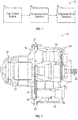
FIG. 1 is a schematic diagram of a generator system of an aircraft; -
FIG. 2 is a cross-sectional schematic view of an example of an integrated drive generator (IDG); -
FIG. 3 is schematic view of a generator, a hydraulic unit, and a differential assembly of the integrated drive generator shown inFIG. 2 ; -
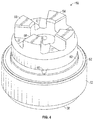
FIG. 4 is a perspective view of a disconnect shaft of the differential assembly according to an embodiment of the invention; -
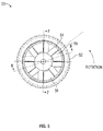
FIG. 5 is a top view of the disconnect shaft ofFIG. 4 according to an embodiment of the invention; -
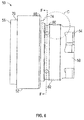
FIG. 6 is a side view of the disconnect shaft ofFIG. 4 according to an embodiment of the invention; -
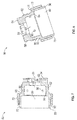
FIG. 7 is a section view of the disconnect shaft ofFIG. 5 taken along line A-A according to an embodiment of the invention; -
FIG. 8 is a section view of the disconnect shaft ofFIG. 5 taken along line B-B according to an embodiment of the invention; -
FIG. 9 is a detailed view of section C of the disconnect shaft ofFIG. 6 according to an embodiment of the invention -
FIG. 10 is a section view of the disconnect shaft ofFIG. 5 taken along line D-D according to an embodiment of the invention; -
FIG. 11 is a section view of the disconnect shaft ofFIG. 5 taken along line E-E according to an embodiment of the invention; and -
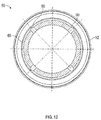
FIG. 12 is a section view of the disconnect shaft ofFIG. 5 taken along line F-F according to an embodiment of the invention. - The detailed description explains embodiments of the invention, together with advantages and features, by way of example with reference to the drawings.
- Referring now to
FIG. 1 , an example of agenerator system 10 is schematically illustrated. Thesystem 10 includes agas turbine engine 12 that provides rotational drive to an integrated drive generator (IDG) 16 through anaccessory drive gearbox 14 mounted on thegas turbine engine 12. Theaccessory drive gearbox 14 is coupled to a spool of theengine 12, and the speed of the spool varies throughout the entire engine operation. - Referring now to
FIGS. 2 and3 , and example of an IDG 16 is illustrated in more detail. As shown, the IDG includes ahousing 18 having generator, center, andinput housing portion generator 40 is arranged in thegenerator housing portion 20.Seal plates 23 are provided on either side of thecenter housing 22 to seal thecenter housing 22 relative to the generator andinput housing portions - An
input shaft 26 receives rotational drive from theaccessory drive gearbox 14. The rotational speed of theinput shaft 26 varies depending upon the operation of theengine 12. To this end, as a result, ahydraulic unit 32 cooperates with thedifferential assembly 28 to convert the variable rotational speed from theinput shaft 26 to provide a fixed rotational output speed to thegenerator 40. - The
input shaft 26 rotationally drives adifferential input gear 30 that is coupled to ahydraulic input gear 34 of thehydraulic unit 32. Thedifferential input gear 30 is operably coupled to theinput shaft 26 by adisconnect assembly 27. The disconnect assembly contains a disconnect shaft to be discussed later. Thehydraulic output gear 36 is coupled to adifferential trim gear 38. Thehydraulic unit 32 increases or decreases the rotational speed provided to thedifferential assembly 28 from thehydraulic output gear 36 to provide a fixed rotational output speed. The variable rotational speed of thedifferential input gear 30 combines with the speed of thedifferential trim gear 38 to provide a fixed rotational speed to agenerator input shaft 42. - Referring now to
FIGS. 4-8 , adisconnect shaft 50 of thedisconnect assembly 27 is illustrated in more detail. Thedisconnect shaft 50 may be formed from a metal material, such as steel for example, and includes a generally cylindrical,non-uniform body 52 having afirst end 54 and a second,opposite end 56. Thefirst end 54 of thedisconnect shaft 50 includes a plurality ofteeth 58 configured to engage a plurality of complementary teeth (not shown) of theinput shaft 26. Together, the plurality ofteeth 58 defines an outer diameter of about 1.200 ± .005 inches (3.048 ± .0127 centimeters) and an inner diameter about .567 ± .001 inches (1.440 ± .00254 centimeters) of thefirst end 54 of theshaft 50. - In the illustrated, non-limiting embodiment, the plurality of
teeth 58 are substantially identical. As shown, theshaft 50 includes four teeth, and a first surface of adjacent teeth is separated by 90°. Eachtooth 58 may be configured to extend over about 3 8° ± 1° of the outer diameter. Achamfer 59 may be formed at the edge of theteeth 58 defining the inner diameter. In one embodiment, thechamfer 59 extends outwardly at an angle of about 30° ± 2° such that the diameter of thechamfer 59 at thefirst end 54 of theshaft 50 is about .627 ±.015 inches (1.593 ± .0381 centimeters). As is visible in the sectional, rollout views of the plurality ofteeth 58 illustrated inFIGS. 10 and 11 , a radius of about .047 ± .005 inches (.119 ± .0127 centimeters) is formed adjacent the opposing sides of eachtooth 56. Aplanar surface 62 extending between the plurality ofteeth 58 is spaced from thefirst end 54 of theteeth 58, parallel to an axis of rotation X of theshaft 50, by about .188 ± .003 inches (.478 ± .0076 centimeters). Theplanar surface 61 may be spaced from a side of thetooth 58 by a distance of about .167 inches (.424 centimeters). Anangled surface 63 connects theplanar surface 61 with the radius adjacent the side of eachtooth 58. In one embodiment, theangled surface 63 extends at a length parallel to the axis of rotation X of theshaft 50 of about .031 ± .010 inches (.079 ± .0254 centimeters). - A
relief 60 is formed about the circumference of theshaft 50 near thefirst end 54 to define afirst portion 62 extending there between. An outer diameter of the body within therelief 60 is about 1.250 ±.010 inches (3.175 ± .0254 centimeters). A chamfer 64 (FIG. 9 ) may be formed at the intersection of therelief 60 and thefirst portion 62 having an angle of about 45° ± 2°. In one embodiment, thefirst portion 62 of thebody 50 includes a plurality of threads configured to couple to another component, such as a disconnect ramp shaft for example. In one embodiment, the plurality of threads have a major diameter between about 1.3044 and 1.3125 inches (3.313-3.334 centimeters), a pitch diameter between about 1.2765 and 1.2800 inches (3.242-3.251 centimeters), a minor diameter between about 1.2482 and 1.2547 inches (3.170- 3.187 centimeters), and a root radius of about .0075 and .0090 inches (.0190-.0029 centimeters). - A
second portion 66 of theshaft 50 is disposed adjacent therelief 60, opposite the first threadedportion 62. As shown, an outer diameter of thesecond portion 66 is about 1.350 +.001 -.000 inches (3.429 +.00254 -.000 centimeters). Achamfer 68 may also be formed at the edge of thesecond portion 66 adjacent therelief 60. In one embodiment, thechamfer 68 extends at an angle of about 45° ± 5° such that a diameter directly adjacent therelief 60 is about 1.320 ± .010 inches (3.353 ± .0254 centimeters). An axial distance between the near edges ofchamfers - A
third portion 70 of theshaft 50 extends from adjacent thesecond portion 66 to thesecond end 56. An axial length of thethird portion 70, parallel to a rotational axis of theshaft 50, is about .697 ± .005 inches (1.770 ± .0127 centimeters). In one embodiment, an outer diameter of thethird portion 70 adjacent thesecond end 56 of theshaft 50 is about 1.500 ± .005 inches (3.81 ± .0127 centimeters). A plurality of outwardly extendingsplines 72 are formed in thethird portion 70 of theshaft 50, adjacent thesecond portion 66. In one embodiment, thefirst splines 72 are constructed as detailed in Table 1.Table 1: External Spline Dimensions Data for External Involute Splines Type Fillet Root Side Fit Class D Pitch Diameter 1.650 in No. of Teeth 33 Pitch Fraction 20/40 Base Circle Diameter 1.4289 in Pressure Angle 30° Max Form Diameter 1.600 in Min Dim. Over Two Wires 1.7827 in Wire Size .0960 in Major Diam 1.700 +.000 -.005 in Minor Diam 1.550 +.000 -.015 in Additional Reqs when Max effective size is not gaged Max Profile Variation .0010 in Max Lead Variation .0003 in Circular Tooth Thickness Max Actual .0713 in Circular Tooth Thickness Min Actual .0693 in Max Diam Over Two Wires 1.7860 in Max Index Variation .0015in - The plurality of
splines 72 may be positioned within thethird portion 70 such that afirst surface 74 of thesplines 72 is separated from the near edge ofchamfer 64 by an axial distance of about .166 ± .010 inches (.422 ± .0254 centimeters), and is separated from thefirst end 54 of theshaft 50 by an axial distance of about .766 ± .003 inches (1.946 ± .0076 centimeters). An axial length of thesplines 72, parallel to the rotational axis X, is about .547 ± .005 inches (1.389 ± .0127 centimeters). In addition, a radius of about .010 ± .005 inches (.0254 ±.0127 centimeters) may be arranged at the intersection between thefirst surface 74 of thesplines 72 and thesecond portion 66. - The
shaft 50 has a non-uniform, substantially hollow interior. Afirst opening 80 formed in theshaft 50 extends an axial distance of about .597 ± .010 inches (1.516 ± .0254 centimeters) from thesecond end 56 and defines an inner diameter within thethird portion 70 of about 1.350 ±.010 inches (3.429 ± .0254 centimeters). Asecond opening 82 formed in theshaft 50 adjacent thefirst opening 80 has a diameter of about 1.050 ± .010 inches (2.667 ± .0254 centimeters) and extends an axial distance of about 1.106 ± .010 inches (2.809 ±.0254 centimeters) from thesecond end 56. The interior comers of one or both of the first andsecond opening chamfer 84 having an angle of about 45° ± 5° and defining an inner diameter of about 1.110 ± .015 inches (2.819 ± .0254 centimeters) may be arranged at the interface between the first andsecond opening - As shown in
FIGS. 6 and12 , a plurality ofholes 90 may be formed within therelief 60 ofbody 52. In the illustrated, non-limiting embodiment, therelief 60 includes four substantially equal and equidistantly spaced holes 90. In the illustrated, non-limiting embodiment, eachhole 90 has a diameter of about .093 ± .005 inches (.236 ± .0127 centimeters). A center of eachhole 90 may be located at a distance parallel to the rotational axis of about .140 inches (.3556 centimeters). - While the invention has been described in detail in connection with only a limited number of embodiments, it should be readily understood that the invention is not limited to such disclosed embodiments. Rather, the invention can be modified to incorporate any number of variations, alterations or substitutions not heretofore described, but which are commensurate with the scope of the invention. Additionally, while various embodiments of the invention have been described, it is to be understood that aspects of the invention may include only some of the described embodiments. Accordingly, the invention is not to be seen as limited by the foregoing description, but is only limited by the scope of the appended claims.
Claims (15)
- A disconnect shaft (50) of an integrated drive generator (IDG), comprising:a body (52) configured to rotate about an axis of rotation and including a first end (54) and a second opposite end (56), a plurality of teeth (58) is formed adjacent the first end (54) and is configured to engage a complementary portion of an adjacent component, a relief (60) is formed in the body (52) such that a first portion (62) is defined between the relief (60) and the plurality of teeth (58), the first portion including a plurality of threads having at least one of a major diameter between about 1.3044 and about 1.3125 inches (3.313-3.334 centimeters), a minor diameter between about 1.2482 and about 1.2547 inches (3.170- 3.187 centimeters), a pitch diameter between about 1.2765 and about 1.2800 inches (3.242-3.251 centimeters), and a root radius between about .0075 and .0090 inches (.0190-.0029 centimeters).
- The disconnect shaft of claim 1, wherein a second portion (66) of the body is arranged adjacent the relief (60), opposite the first portion, the second portion having an outer diameter between about 1.350 + .001 - .000 inches (3.429 +.00254 -.000 centimeters).
- The disconnect shaft of claim 2, wherein a third portion (70) of the body (52) extends from adjacent the second portion (66) to the second end (56), the third portion (70) having an axial length parallel to axis of rotation of about .697 ± .005 inches (1.770 ± .0127 centimeters) and an outer diameter adjacent the second end of about 1.500 ± .005 inches (3.81 ± .0127 centimeters).
- The disconnect shaft according to claim 3, wherein the third portion (70) of the shaft includes a plurality of outwardly extending splines (72).
- The disconnect shaft according to claim 4, wherein the plurality of splines (72) are constructed in accordance with Table 1.
- The disconnect shaft of any preceding claim, wherein an outer diameter defined by the plurality of teeth (58) at the first end is about 1.200 ± .005 inches (3.048 ± .0127 centimeters), an inner diameter defined by the plurality of teeth at the first end is about .567 ± .001 inches (1.440 ± .00254 centimeters).
- The disconnect shaft of any preceding claim, wherein the plurality of teeth (58) includes four substantially identical teeth, wherein each tooth extending about each 38° ± 1° of a circumference of the body, and a first surface of adjacent teeth are separated by 90 degrees.
- The disconnect shaft of claim 7, wherein a chamfer is formed at the first end of the teeth, the chamfer extending outwardly at an angle of about 30° ± 2° such that a diameter of the chamfer 0 at the first end is about .627 ±.015 inches (1.593 ± .0381 centimeters).
- The disconnect shaft of claim 7, wherein a radius of about .047 ± .005 inches (.119 ± .0127 centimeters) is formed adjacent at least one side of each of the plurality of teeth.
- The disconnect shaft of claim 9, wherein a planar surface parallel to the first end (54) extends between the plurality of the teeth (58), the planar surface being spaced from the first end of the teeth, parallel to the axis of rotation, by about .188 ± .003 inches (.478 ± .0076 centimeters), and spaced from an adjacent side of one of the plurality of teeth by a distance of about .167 inches (.424 centimeters), wherein an angled surface connects the planar surface with the radius, the angled surface extending at a length parallel to the axis of rotation of about .031 ± .010 inches (.079 ± .0254 centimeters).
- The disconnect shaft of claim 2, wherein a chamfer (84) is formed at an intersection between the relief and the first portion, the chamfer having an angle of about 45° ± 2°.
- The disconnect shaft of any preceding claim, wherein a chamfer (84) is formed at an intersection between the relief and the second portion, the chamfer having an angle of about 45° ± 52° such that a diameter of the body directly adjacent the relief is about 1.320 ± .010 inches (3.353 ± .0254 centimeters); an axial distance between the near edges of chamfers 64 and 68 may be about .070 ± .010 inches (.1178 ± .0254 centimeters).
- The disconnect shaft of claim 12, wherein an axial distance between a near edge of both the chamfer formed between the relief and the first portion and the chamfer formed between the relief and the second portion is about .070 ± .010 inches (. 1178 ± .0254 centimeters).
- The disconnect shaft of any preceding claim, wherein a first interior opening (80) is formed in the shaft, the first interior opening extend an axial distance parallel to the axis of rotation of about 597 ± .010 inches (1.516 ± .0254 centimeters) from the second end and defines an inner diameter of about 1.350 ±.010 inches (3.429 ± .0254 centimeters).
- The disconnect shaft of any preceding claim, wherein a second interior opening (82) is formed in the shaft adjacent the first interior opening, second interior opening extending an axial distance parallel to the axis of rotation of about 1.106 ± .010 inches (2.809 ±.0254 centimeters) and defining an inner diameter of about 1.050 ± .010 inches (2.667 ± .0254 centimeters).
Applications Claiming Priority (1)
| Application Number | Priority Date | Filing Date | Title |
|---|---|---|---|
| US14/685,957 US9732804B2 (en) | 2015-04-14 | 2015-04-14 | Disconnect shaft for an integrated drive generator (IDG) |
Publications (2)
| Publication Number | Publication Date |
|---|---|
| EP3081824A1 true EP3081824A1 (en) | 2016-10-19 |
| EP3081824B1 EP3081824B1 (en) | 2020-04-22 |
Family
ID=55750337
Family Applications (1)
| Application Number | Title | Priority Date | Filing Date |
|---|---|---|---|
| EP16164751.6A Active EP3081824B1 (en) | 2015-04-14 | 2016-04-11 | Disconnect shaft for an integrated drive generator (idg) |
Country Status (2)
| Country | Link |
|---|---|
| US (1) | US9732804B2 (en) |
| EP (1) | EP3081824B1 (en) |
Families Citing this family (2)
| Publication number | Priority date | Publication date | Assignee | Title |
|---|---|---|---|---|
| US10634063B2 (en) | 2018-01-04 | 2020-04-28 | Hamilton Sundstrand Corporation | Input shaft for use in integrated drive generator |
| US12512729B2 (en) * | 2023-01-30 | 2025-12-30 | Honeywell International Inc. | Resetting an electromechanical disconnect |
Citations (3)
| Publication number | Priority date | Publication date | Assignee | Title |
|---|---|---|---|---|
| US4610558A (en) * | 1983-09-15 | 1986-09-09 | Erickson Mervin L | Selectively free wheeling or drive hub for vehicles |
| US4856633A (en) * | 1988-03-31 | 1989-08-15 | Specht Victor J | Wheel hub assembly |
| US20140008170A1 (en) * | 2012-07-06 | 2014-01-09 | Henry R. Vanderzyden | Integrated drive generator disconnect assembly |
Family Cites Families (13)
| Publication number | Priority date | Publication date | Assignee | Title |
|---|---|---|---|---|
| US3441116A (en) * | 1966-12-13 | 1969-04-29 | United Aircraft Corp | Electrically operated clutch mechanism |
| US4244455A (en) | 1978-10-17 | 1981-01-13 | The United States Of America As Represented By The Secretary Of The Navy | Rotary shaft decoupling mechanism |
| US4997072A (en) | 1989-08-21 | 1991-03-05 | Sundstrand Corporation | Rotating concentric shaft disconnect actuating mechanism for an integrated drive generator |
| US5031740A (en) | 1989-11-27 | 1991-07-16 | Sundstrand Corporation | High speed cam actuated disconnect |
| US5103949A (en) | 1990-11-08 | 1992-04-14 | Sundstrand Corporation | Thermal disconnect |
| GB0329703D0 (en) | 2003-12-22 | 2004-01-28 | Goodrich Control Sys Ltd | Drive disconnect device |
| US20050217961A1 (en) | 2004-04-01 | 2005-10-06 | Planet Products Corporation | Quick disconnect coupling |
| US7946403B2 (en) * | 2008-03-04 | 2011-05-24 | Honeywell International Inc. | Mechanical disconnect dual-sided interlocking teeth |
| GB0804123D0 (en) | 2008-03-05 | 2008-04-09 | Goodrich Control Sys Ltd | Drive disconnect device |
| US8237298B2 (en) * | 2008-12-22 | 2012-08-07 | Hamilton Sundstrand Corporation | Generator coupling for use with gas turbine engine |
| US8963391B2 (en) | 2009-05-06 | 2015-02-24 | Hamilton Sundstrand Corporation | Decoupler shaft for high speed generator |
| US8388486B2 (en) | 2009-08-11 | 2013-03-05 | Magna Powertrain Of America, Inc. | AWD vehicle with active disconnect coupling having multi-stage ball ramp |
| CA2738435C (en) | 2010-08-04 | 2018-05-29 | Auburn Gear, Inc. | Quick disconnect for a drive unit |
-
2015
- 2015-04-14 US US14/685,957 patent/US9732804B2/en active Active
-
2016
- 2016-04-11 EP EP16164751.6A patent/EP3081824B1/en active Active
Patent Citations (3)
| Publication number | Priority date | Publication date | Assignee | Title |
|---|---|---|---|---|
| US4610558A (en) * | 1983-09-15 | 1986-09-09 | Erickson Mervin L | Selectively free wheeling or drive hub for vehicles |
| US4856633A (en) * | 1988-03-31 | 1989-08-15 | Specht Victor J | Wheel hub assembly |
| US20140008170A1 (en) * | 2012-07-06 | 2014-01-09 | Henry R. Vanderzyden | Integrated drive generator disconnect assembly |
Also Published As
| Publication number | Publication date |
|---|---|
| US9732804B2 (en) | 2017-08-15 |
| US20160305491A1 (en) | 2016-10-20 |
| EP3081824B1 (en) | 2020-04-22 |
Similar Documents
| Publication | Publication Date | Title |
|---|---|---|
| EP3023616B1 (en) | Variable shaft for hydraulic unit | |
| EP3312475B1 (en) | Compound harmonic drive assembly | |
| JP5932546B2 (en) | Planetary gear train and corresponding manufacturing method | |
| EP3165795A1 (en) | Flex spine for use with a compound harmonic generator | |
| US4685823A (en) | Antibacklash shaft coupling | |
| EP3296591A1 (en) | Ring gear and gear device | |
| EP2910740B1 (en) | Variable vane sychronization ring transmission mechanisms | |
| EP3081824B1 (en) | Disconnect shaft for an integrated drive generator (idg) | |
| EP3023651B1 (en) | Fixed shaft for hydraulic unit | |
| US9677663B2 (en) | Gear geometry with fluid reservoir and fluid paths | |
| EP3128208B1 (en) | Vehicle differential | |
| US9964180B2 (en) | Gearing having a pinion and a wheel | |
| EP3348852B1 (en) | Crowning of a spline in a direction perpendicular to a spline tooth face | |
| EP3184856A1 (en) | Planetary drive device and jet engine having a planetary drive device | |
| EP3412394A1 (en) | Tool for machining modified gear of rov thruster | |
| US10814543B2 (en) | Transmission gear system of multi-screw extruder or kneader | |
| JP6800095B2 (en) | gear | |
| EP2778445A1 (en) | Bimetallic shaft for gearbox systems to limit wear and corrosion | |
| EP3034900B1 (en) | Fixed coaxial shaft for a hydraulic unit | |
| EP2908029B1 (en) | Electric generator oil pump driven gear | |
| US20170050727A1 (en) | Radially compliant quill shaft | |
| US10710709B2 (en) | Mechanical system for transmitting motion and an aircraft fitted with a corresponding system | |
| US12049943B1 (en) | Flexured sun gears for planetary gear systems | |
| US20060003847A1 (en) | Coupling capable of accommodating large angular and axial displacements | |
| CN108006195A (en) | The variable gear of a kind of transverse tooth thickness and helical angle and adjustment structure |
Legal Events
| Date | Code | Title | Description |
|---|---|---|---|
| PUAI | Public reference made under article 153(3) epc to a published international application that has entered the european phase |
Free format text: ORIGINAL CODE: 0009012 |
|
| AK | Designated contracting states |
Kind code of ref document: A1 Designated state(s): AL AT BE BG CH CY CZ DE DK EE ES FI FR GB GR HR HU IE IS IT LI LT LU LV MC MK MT NL NO PL PT RO RS SE SI SK SM TR |
|
| AX | Request for extension of the european patent |
Extension state: BA ME |
|
| STAA | Information on the status of an ep patent application or granted ep patent |
Free format text: STATUS: REQUEST FOR EXAMINATION WAS MADE |
|
| 17P | Request for examination filed |
Effective date: 20170419 |
|
| RBV | Designated contracting states (corrected) |
Designated state(s): AL AT BE BG CH CY CZ DE DK EE ES FI FR GB GR HR HU IE IS IT LI LT LU LV MC MK MT NL NO PL PT RO RS SE SI SK SM TR |
|
| GRAP | Despatch of communication of intention to grant a patent |
Free format text: ORIGINAL CODE: EPIDOSNIGR1 |
|
| STAA | Information on the status of an ep patent application or granted ep patent |
Free format text: STATUS: GRANT OF PATENT IS INTENDED |
|
| INTG | Intention to grant announced |
Effective date: 20190624 |
|
| GRAJ | Information related to disapproval of communication of intention to grant by the applicant or resumption of examination proceedings by the epo deleted |
Free format text: ORIGINAL CODE: EPIDOSDIGR1 |
|
| STAA | Information on the status of an ep patent application or granted ep patent |
Free format text: STATUS: REQUEST FOR EXAMINATION WAS MADE |
|
| GRAP | Despatch of communication of intention to grant a patent |
Free format text: ORIGINAL CODE: EPIDOSNIGR1 |
|
| STAA | Information on the status of an ep patent application or granted ep patent |
Free format text: STATUS: GRANT OF PATENT IS INTENDED |
|
| INTC | Intention to grant announced (deleted) | ||
| INTG | Intention to grant announced |
Effective date: 20191114 |
|
| GRAS | Grant fee paid |
Free format text: ORIGINAL CODE: EPIDOSNIGR3 |
|
| GRAA | (expected) grant |
Free format text: ORIGINAL CODE: 0009210 |
|
| STAA | Information on the status of an ep patent application or granted ep patent |
Free format text: STATUS: THE PATENT HAS BEEN GRANTED |
|
| AK | Designated contracting states |
Kind code of ref document: B1 Designated state(s): AL AT BE BG CH CY CZ DE DK EE ES FI FR GB GR HR HU IE IS IT LI LT LU LV MC MK MT NL NO PL PT RO RS SE SI SK SM TR |
|
| REG | Reference to a national code |
Ref country code: CH Ref legal event code: EP |
|
| REG | Reference to a national code |
Ref country code: IE Ref legal event code: FG4D |
|
| REG | Reference to a national code |
Ref country code: DE Ref legal event code: R096 Ref document number: 602016034367 Country of ref document: DE |
|
| REG | Reference to a national code |
Ref country code: AT Ref legal event code: REF Ref document number: 1260516 Country of ref document: AT Kind code of ref document: T Effective date: 20200515 |
|
| REG | Reference to a national code |
Ref country code: LT Ref legal event code: MG4D |
|
| REG | Reference to a national code |
Ref country code: NL Ref legal event code: MP Effective date: 20200422 |
|
| PG25 | Lapsed in a contracting state [announced via postgrant information from national office to epo] |
Ref country code: IS Free format text: LAPSE BECAUSE OF FAILURE TO SUBMIT A TRANSLATION OF THE DESCRIPTION OR TO PAY THE FEE WITHIN THE PRESCRIBED TIME-LIMIT Effective date: 20200822 Ref country code: FI Free format text: LAPSE BECAUSE OF FAILURE TO SUBMIT A TRANSLATION OF THE DESCRIPTION OR TO PAY THE FEE WITHIN THE PRESCRIBED TIME-LIMIT Effective date: 20200422 Ref country code: PT Free format text: LAPSE BECAUSE OF FAILURE TO SUBMIT A TRANSLATION OF THE DESCRIPTION OR TO PAY THE FEE WITHIN THE PRESCRIBED TIME-LIMIT Effective date: 20200824 Ref country code: SE Free format text: LAPSE BECAUSE OF FAILURE TO SUBMIT A TRANSLATION OF THE DESCRIPTION OR TO PAY THE FEE WITHIN THE PRESCRIBED TIME-LIMIT Effective date: 20200422 Ref country code: NL Free format text: LAPSE BECAUSE OF FAILURE TO SUBMIT A TRANSLATION OF THE DESCRIPTION OR TO PAY THE FEE WITHIN THE PRESCRIBED TIME-LIMIT Effective date: 20200422 Ref country code: LT Free format text: LAPSE BECAUSE OF FAILURE TO SUBMIT A TRANSLATION OF THE DESCRIPTION OR TO PAY THE FEE WITHIN THE PRESCRIBED TIME-LIMIT Effective date: 20200422 Ref country code: GR Free format text: LAPSE BECAUSE OF FAILURE TO SUBMIT A TRANSLATION OF THE DESCRIPTION OR TO PAY THE FEE WITHIN THE PRESCRIBED TIME-LIMIT Effective date: 20200723 Ref country code: NO Free format text: LAPSE BECAUSE OF FAILURE TO SUBMIT A TRANSLATION OF THE DESCRIPTION OR TO PAY THE FEE WITHIN THE PRESCRIBED TIME-LIMIT Effective date: 20200722 |
|
| REG | Reference to a national code |
Ref country code: AT Ref legal event code: MK05 Ref document number: 1260516 Country of ref document: AT Kind code of ref document: T Effective date: 20200422 |
|
| PG25 | Lapsed in a contracting state [announced via postgrant information from national office to epo] |
Ref country code: BG Free format text: LAPSE BECAUSE OF FAILURE TO SUBMIT A TRANSLATION OF THE DESCRIPTION OR TO PAY THE FEE WITHIN THE PRESCRIBED TIME-LIMIT Effective date: 20200722 Ref country code: LV Free format text: LAPSE BECAUSE OF FAILURE TO SUBMIT A TRANSLATION OF THE DESCRIPTION OR TO PAY THE FEE WITHIN THE PRESCRIBED TIME-LIMIT Effective date: 20200422 Ref country code: RS Free format text: LAPSE BECAUSE OF FAILURE TO SUBMIT A TRANSLATION OF THE DESCRIPTION OR TO PAY THE FEE WITHIN THE PRESCRIBED TIME-LIMIT Effective date: 20200422 Ref country code: HR Free format text: LAPSE BECAUSE OF FAILURE TO SUBMIT A TRANSLATION OF THE DESCRIPTION OR TO PAY THE FEE WITHIN THE PRESCRIBED TIME-LIMIT Effective date: 20200422 |
|
| PG25 | Lapsed in a contracting state [announced via postgrant information from national office to epo] |
Ref country code: AL Free format text: LAPSE BECAUSE OF FAILURE TO SUBMIT A TRANSLATION OF THE DESCRIPTION OR TO PAY THE FEE WITHIN THE PRESCRIBED TIME-LIMIT Effective date: 20200422 |
|
| REG | Reference to a national code |
Ref country code: DE Ref legal event code: R097 Ref document number: 602016034367 Country of ref document: DE |
|
| PG25 | Lapsed in a contracting state [announced via postgrant information from national office to epo] |
Ref country code: DK Free format text: LAPSE BECAUSE OF FAILURE TO SUBMIT A TRANSLATION OF THE DESCRIPTION OR TO PAY THE FEE WITHIN THE PRESCRIBED TIME-LIMIT Effective date: 20200422 Ref country code: ES Free format text: LAPSE BECAUSE OF FAILURE TO SUBMIT A TRANSLATION OF THE DESCRIPTION OR TO PAY THE FEE WITHIN THE PRESCRIBED TIME-LIMIT Effective date: 20200422 Ref country code: SM Free format text: LAPSE BECAUSE OF FAILURE TO SUBMIT A TRANSLATION OF THE DESCRIPTION OR TO PAY THE FEE WITHIN THE PRESCRIBED TIME-LIMIT Effective date: 20200422 Ref country code: RO Free format text: LAPSE BECAUSE OF FAILURE TO SUBMIT A TRANSLATION OF THE DESCRIPTION OR TO PAY THE FEE WITHIN THE PRESCRIBED TIME-LIMIT Effective date: 20200422 Ref country code: EE Free format text: LAPSE BECAUSE OF FAILURE TO SUBMIT A TRANSLATION OF THE DESCRIPTION OR TO PAY THE FEE WITHIN THE PRESCRIBED TIME-LIMIT Effective date: 20200422 Ref country code: AT Free format text: LAPSE BECAUSE OF FAILURE TO SUBMIT A TRANSLATION OF THE DESCRIPTION OR TO PAY THE FEE WITHIN THE PRESCRIBED TIME-LIMIT Effective date: 20200422 Ref country code: CZ Free format text: LAPSE BECAUSE OF FAILURE TO SUBMIT A TRANSLATION OF THE DESCRIPTION OR TO PAY THE FEE WITHIN THE PRESCRIBED TIME-LIMIT Effective date: 20200422 Ref country code: IT Free format text: LAPSE BECAUSE OF FAILURE TO SUBMIT A TRANSLATION OF THE DESCRIPTION OR TO PAY THE FEE WITHIN THE PRESCRIBED TIME-LIMIT Effective date: 20200422 |
|
| PG25 | Lapsed in a contracting state [announced via postgrant information from national office to epo] |
Ref country code: PL Free format text: LAPSE BECAUSE OF FAILURE TO SUBMIT A TRANSLATION OF THE DESCRIPTION OR TO PAY THE FEE WITHIN THE PRESCRIBED TIME-LIMIT Effective date: 20200422 Ref country code: SK Free format text: LAPSE BECAUSE OF FAILURE TO SUBMIT A TRANSLATION OF THE DESCRIPTION OR TO PAY THE FEE WITHIN THE PRESCRIBED TIME-LIMIT Effective date: 20200422 |
|
| PLBE | No opposition filed within time limit |
Free format text: ORIGINAL CODE: 0009261 |
|
| STAA | Information on the status of an ep patent application or granted ep patent |
Free format text: STATUS: NO OPPOSITION FILED WITHIN TIME LIMIT |
|
| 26N | No opposition filed |
Effective date: 20210125 |
|
| PG25 | Lapsed in a contracting state [announced via postgrant information from national office to epo] |
Ref country code: SI Free format text: LAPSE BECAUSE OF FAILURE TO SUBMIT A TRANSLATION OF THE DESCRIPTION OR TO PAY THE FEE WITHIN THE PRESCRIBED TIME-LIMIT Effective date: 20200422 |
|
| REG | Reference to a national code |
Ref country code: DE Ref legal event code: R119 Ref document number: 602016034367 Country of ref document: DE |
|
| PG25 | Lapsed in a contracting state [announced via postgrant information from national office to epo] |
Ref country code: MC Free format text: LAPSE BECAUSE OF FAILURE TO SUBMIT A TRANSLATION OF THE DESCRIPTION OR TO PAY THE FEE WITHIN THE PRESCRIBED TIME-LIMIT Effective date: 20200422 |
|
| PG25 | Lapsed in a contracting state [announced via postgrant information from national office to epo] |
Ref country code: LU Free format text: LAPSE BECAUSE OF NON-PAYMENT OF DUE FEES Effective date: 20210411 |
|
| REG | Reference to a national code |
Ref country code: BE Ref legal event code: MM Effective date: 20210430 |
|
| PG25 | Lapsed in a contracting state [announced via postgrant information from national office to epo] |
Ref country code: DE Free format text: LAPSE BECAUSE OF NON-PAYMENT OF DUE FEES Effective date: 20211103 Ref country code: CH Free format text: LAPSE BECAUSE OF NON-PAYMENT OF DUE FEES Effective date: 20210430 Ref country code: LI Free format text: LAPSE BECAUSE OF NON-PAYMENT OF DUE FEES Effective date: 20210430 |
|
| PG25 | Lapsed in a contracting state [announced via postgrant information from national office to epo] |
Ref country code: IE Free format text: LAPSE BECAUSE OF NON-PAYMENT OF DUE FEES Effective date: 20210411 |
|
| PG25 | Lapsed in a contracting state [announced via postgrant information from national office to epo] |
Ref country code: BE Free format text: LAPSE BECAUSE OF NON-PAYMENT OF DUE FEES Effective date: 20210430 |
|
| PG25 | Lapsed in a contracting state [announced via postgrant information from national office to epo] |
Ref country code: HU Free format text: LAPSE BECAUSE OF FAILURE TO SUBMIT A TRANSLATION OF THE DESCRIPTION OR TO PAY THE FEE WITHIN THE PRESCRIBED TIME-LIMIT; INVALID AB INITIO Effective date: 20160411 |
|
| P01 | Opt-out of the competence of the unified patent court (upc) registered |
Effective date: 20230522 |
|
| PG25 | Lapsed in a contracting state [announced via postgrant information from national office to epo] |
Ref country code: CY Free format text: LAPSE BECAUSE OF FAILURE TO SUBMIT A TRANSLATION OF THE DESCRIPTION OR TO PAY THE FEE WITHIN THE PRESCRIBED TIME-LIMIT Effective date: 20200422 |
|
| PG25 | Lapsed in a contracting state [announced via postgrant information from national office to epo] |
Ref country code: MK Free format text: LAPSE BECAUSE OF FAILURE TO SUBMIT A TRANSLATION OF THE DESCRIPTION OR TO PAY THE FEE WITHIN THE PRESCRIBED TIME-LIMIT Effective date: 20200422 |
|
| PG25 | Lapsed in a contracting state [announced via postgrant information from national office to epo] |
Ref country code: TR Free format text: LAPSE BECAUSE OF FAILURE TO SUBMIT A TRANSLATION OF THE DESCRIPTION OR TO PAY THE FEE WITHIN THE PRESCRIBED TIME-LIMIT Effective date: 20200422 |
|
| PG25 | Lapsed in a contracting state [announced via postgrant information from national office to epo] |
Ref country code: MT Free format text: LAPSE BECAUSE OF FAILURE TO SUBMIT A TRANSLATION OF THE DESCRIPTION OR TO PAY THE FEE WITHIN THE PRESCRIBED TIME-LIMIT Effective date: 20200422 |
|
| PGFP | Annual fee paid to national office [announced via postgrant information from national office to epo] |
Ref country code: GB Payment date: 20260319 Year of fee payment: 11 |
|
| PGFP | Annual fee paid to national office [announced via postgrant information from national office to epo] |
Ref country code: FR Payment date: 20260319 Year of fee payment: 11 |