EP3081800A1 - Fuel withdrawing system from a reservoir of compressed natural gas to supply an internal combustion engine - Google Patents
Fuel withdrawing system from a reservoir of compressed natural gas to supply an internal combustion engine Download PDFInfo
- Publication number
- EP3081800A1 EP3081800A1 EP16165006.4A EP16165006A EP3081800A1 EP 3081800 A1 EP3081800 A1 EP 3081800A1 EP 16165006 A EP16165006 A EP 16165006A EP 3081800 A1 EP3081800 A1 EP 3081800A1
- Authority
- EP
- European Patent Office
- Prior art keywords
- internal combustion
- reservoir
- combustion engine
- fraction
- condensed fraction
- Prior art date
- Legal status (The legal status is an assumption and is not a legal conclusion. Google has not performed a legal analysis and makes no representation as to the accuracy of the status listed.)
- Granted
Links
Images
Classifications
-
- F—MECHANICAL ENGINEERING; LIGHTING; HEATING; WEAPONS; BLASTING
- F02—COMBUSTION ENGINES; HOT-GAS OR COMBUSTION-PRODUCT ENGINE PLANTS
- F02M—SUPPLYING COMBUSTION ENGINES IN GENERAL WITH COMBUSTIBLE MIXTURES OR CONSTITUENTS THEREOF
- F02M21/00—Apparatus for supplying engines with non-liquid fuels, e.g. gaseous fuels stored in liquid form
- F02M21/02—Apparatus for supplying engines with non-liquid fuels, e.g. gaseous fuels stored in liquid form for gaseous fuels
- F02M21/0203—Apparatus for supplying engines with non-liquid fuels, e.g. gaseous fuels stored in liquid form for gaseous fuels characterised by the type of gaseous fuel
- F02M21/0209—Hydrocarbon fuels, e.g. methane or acetylene
- F02M21/0212—Hydrocarbon fuels, e.g. methane or acetylene comprising at least 3 C-Atoms, e.g. liquefied petroleum gas [LPG], propane or butane
-
- F—MECHANICAL ENGINEERING; LIGHTING; HEATING; WEAPONS; BLASTING
- F02—COMBUSTION ENGINES; HOT-GAS OR COMBUSTION-PRODUCT ENGINE PLANTS
- F02D—CONTROLLING COMBUSTION ENGINES
- F02D19/00—Controlling engines characterised by their use of non-liquid fuels, pluralities of fuels, or non-fuel substances added to the combustible mixtures
- F02D19/02—Controlling engines characterised by their use of non-liquid fuels, pluralities of fuels, or non-fuel substances added to the combustible mixtures peculiar to engines working with gaseous fuels
- F02D19/026—Measuring or estimating parameters related to the fuel supply system
- F02D19/027—Determining the fuel pressure, temperature or volume flow, the fuel tank fill level or a valve position
-
- F—MECHANICAL ENGINEERING; LIGHTING; HEATING; WEAPONS; BLASTING
- F02—COMBUSTION ENGINES; HOT-GAS OR COMBUSTION-PRODUCT ENGINE PLANTS
- F02M—SUPPLYING COMBUSTION ENGINES IN GENERAL WITH COMBUSTIBLE MIXTURES OR CONSTITUENTS THEREOF
- F02M21/00—Apparatus for supplying engines with non-liquid fuels, e.g. gaseous fuels stored in liquid form
- F02M21/02—Apparatus for supplying engines with non-liquid fuels, e.g. gaseous fuels stored in liquid form for gaseous fuels
- F02M21/0218—Details on the gaseous fuel supply system, e.g. tanks, valves, pipes, pumps, rails, injectors or mixers
- F02M21/023—Valves; Pressure or flow regulators in the fuel supply or return system
-
- F—MECHANICAL ENGINEERING; LIGHTING; HEATING; WEAPONS; BLASTING
- F02—COMBUSTION ENGINES; HOT-GAS OR COMBUSTION-PRODUCT ENGINE PLANTS
- F02M—SUPPLYING COMBUSTION ENGINES IN GENERAL WITH COMBUSTIBLE MIXTURES OR CONSTITUENTS THEREOF
- F02M21/00—Apparatus for supplying engines with non-liquid fuels, e.g. gaseous fuels stored in liquid form
- F02M21/02—Apparatus for supplying engines with non-liquid fuels, e.g. gaseous fuels stored in liquid form for gaseous fuels
- F02M21/0218—Details on the gaseous fuel supply system, e.g. tanks, valves, pipes, pumps, rails, injectors or mixers
- F02M21/0287—Details on the gaseous fuel supply system, e.g. tanks, valves, pipes, pumps, rails, injectors or mixers characterised by the transition from liquid to gaseous phase ; Injection in liquid phase; Cooling and low temperature storage
-
- F—MECHANICAL ENGINEERING; LIGHTING; HEATING; WEAPONS; BLASTING
- F02—COMBUSTION ENGINES; HOT-GAS OR COMBUSTION-PRODUCT ENGINE PLANTS
- F02D—CONTROLLING COMBUSTION ENGINES
- F02D41/00—Electrical control of supply of combustible mixture or its constituents
- F02D41/0025—Controlling engines characterised by use of non-liquid fuels, pluralities of fuels, or non-fuel substances added to the combustible mixtures
- F02D41/0027—Controlling engines characterised by use of non-liquid fuels, pluralities of fuels, or non-fuel substances added to the combustible mixtures the fuel being gaseous
-
- F—MECHANICAL ENGINEERING; LIGHTING; HEATING; WEAPONS; BLASTING
- F02—COMBUSTION ENGINES; HOT-GAS OR COMBUSTION-PRODUCT ENGINE PLANTS
- F02M—SUPPLYING COMBUSTION ENGINES IN GENERAL WITH COMBUSTIBLE MIXTURES OR CONSTITUENTS THEREOF
- F02M21/00—Apparatus for supplying engines with non-liquid fuels, e.g. gaseous fuels stored in liquid form
- F02M21/02—Apparatus for supplying engines with non-liquid fuels, e.g. gaseous fuels stored in liquid form for gaseous fuels
- F02M21/0218—Details on the gaseous fuel supply system, e.g. tanks, valves, pipes, pumps, rails, injectors or mixers
- F02M21/0221—Fuel storage reservoirs, e.g. cryogenic tanks
- F02M21/0224—Secondary gaseous fuel storages
-
- F—MECHANICAL ENGINEERING; LIGHTING; HEATING; WEAPONS; BLASTING
- F02—COMBUSTION ENGINES; HOT-GAS OR COMBUSTION-PRODUCT ENGINE PLANTS
- F02M—SUPPLYING COMBUSTION ENGINES IN GENERAL WITH COMBUSTIBLE MIXTURES OR CONSTITUENTS THEREOF
- F02M21/00—Apparatus for supplying engines with non-liquid fuels, e.g. gaseous fuels stored in liquid form
- F02M21/02—Apparatus for supplying engines with non-liquid fuels, e.g. gaseous fuels stored in liquid form for gaseous fuels
- F02M21/06—Apparatus for de-liquefying, e.g. by heating
-
- Y—GENERAL TAGGING OF NEW TECHNOLOGICAL DEVELOPMENTS; GENERAL TAGGING OF CROSS-SECTIONAL TECHNOLOGIES SPANNING OVER SEVERAL SECTIONS OF THE IPC; TECHNICAL SUBJECTS COVERED BY FORMER USPC CROSS-REFERENCE ART COLLECTIONS [XRACs] AND DIGESTS
- Y02—TECHNOLOGIES OR APPLICATIONS FOR MITIGATION OR ADAPTATION AGAINST CLIMATE CHANGE
- Y02T—CLIMATE CHANGE MITIGATION TECHNOLOGIES RELATED TO TRANSPORTATION
- Y02T10/00—Road transport of goods or passengers
- Y02T10/10—Internal combustion engine [ICE] based vehicles
- Y02T10/30—Use of alternative fuels, e.g. biofuels
Definitions
- the invention relates to the field of engine-driven vehicles provided with internal combustion engines supplied by a compressed gaseous fuel.
- Methane is one of the most ecological fuels used to supply internal combustion engines with a controlled ignition, namely those provided with a spark plug for the fuel mixture. Methane is usually stored in suitable reservoirs in a compressed gaseous phase, with pressures close to 220 bar.
- methane is not pure methane, but it also contains propane and ethane (or ethylene) in a minimum fraction amounting to 13% by volume.
- the fractions of propane and ethane tend to condense in the vehicle reservoir in order to then tend to re-gasify, when below a predefined threshold, the inner pressure of the reservoir reduces due to the withdrawing of the methane itself.
- pure methane has an octane number that is very different, approximately 130, from a mixture in which propane and ethane make up significant fractions. Indeed, a mixture of propane and ethane has an octane number of approximately 105.
- methane or "natural gas” indicate a methane-based mixture also containing propane and ethane. If, on the other hand, the term “pure methane” is used, reference is made to methane CH4.
- the object of the invention is to overcome the limits of the prior art by providing a fuel withdrawing system, from a relative reservoir of compressed natural gas, to supply an internal combustion engine
- the idea on which the invention is based is that of separately withdrawing a gaseous phase and a liquid phase, also called condensed fraction, from a methane reservoir, so as to supply a relative internal combustion engine.
- first opening also called high opening
- second opening also called low opening
- the same opening can be used to introduce two tubes, one having the relative opening arranged in a high part of the cylinder and the other one having a relative opening arranged in a low part of the cylinder.
- the subject-matter of this invention is a fuel withdrawing system from a reservoir of compressed natural gas to supply an internal combustion engine according to claim 1.
- the liquid phase and the gaseous phase are withdrawn simultaneously, at least immediately after a refuelling, and in a predefined mass or volume ratio relative to one another, so as to be supplied together to the internal combustion engine.
- the system can supply a desired mixture in terms of anti-knocking properties and octane number, at least until the aforesaid pressure threshold is reached, below which the liquid phase starts gasifying in the reservoir. Therefore, the performances of the internal combustion engines are not jeopardized as described above.
- the mixing ratio between the liquid phase and the gaseous phase is varied according to the engine point. Indeed, when the internal combustion engines operates in conditions in which a lower octane number is tolerable, the fuel supplied to the internal combustion engine comprises a more significant or total percentage of liquid phase, whereas, when the internal combustion engine operates in conditions in which a higher octane number is necessary, the percentage of liquid phase is drastically reduced or eliminated.
- the operating parameters of the internal combustion engine are varied according to the methane-propane/ethane ratio supplied to the internal combustion engine.
- These operating parameters can be the injection times, the mixture ignition times, the opening and closing angles of the valves, if they are adjustable, and the intervention of a wastegate valve, in case of a supercharged internal combustion engine.
- a second reservoir is associated with said low opening of the first reservoir and is intermediate between said first reservoir and the fuel injection system of the internal combustion engine.
- Automatic transfer means are adapted to transfer the sole liquid phase (or condensed fraction) from the first reservoir to the second reservoir, so that it can freely gasify as the first reservoir empties. In this way, one can properly control the fuel mixture supplied to the internal combustion engine, without having to implement complicated algorithms for the estimation thereof.
- the supply system of the internal combustion engine simultaneously comprises a pressure reduction device for the gaseous phase and a vaporisation device for the liquid fraction.
- the output pressure is the same for the reduction device and the vaporisation device, so as allow the fractions to be more easily mixed during the injection into the engine cylinders.
- Another subject-matter of the invention is a terrestrial vehicle provided with an internal combustion engine with a controlled ignition, with at least one first reservoir intended to be filled with a methane-based mixture, and with a reservoir withdrawing system described above.
- second component does not imply the presence of a "first” component.
- first component does not imply the presence of a "first” component.
- a reservoir TK for compressed natural gas comprises a high opening HO and a low opening LO, so as to allow the gaseous phase GF and the liquid or condensed phase LF to be withdrawn from the reservoir TK separately and independently.
- a first duct GP establishes a communication between said high opening HO and injection means J cooperating with an internal combustion engine E.
- a second duct LP establishes a communication between said low opening LO and said injection means J cooperating with an internal combustion engine E.
- a pressure reduction device PR which is adapted to adapt the pressure of the gaseous phase to a predefined injection pressure.
- a vaporisation device VP which is adapted to gasify the withdrawn condensed phase LP, so as to obtain a predefined output pressure, which is adequate for the injection into the cylinders of the internal combustion engine.
- the gaseous phase has a completely different nature compared to the liquid phase, since, whereas the gaseous phase relates to a non-condensable chemical composition, the liquid phase relates to a condensable mixture of compositions, which is completely different from the first one.
- a processing unit for example the engine control unit ECU, controls the withdrawing of the liquid and gaseous phases and the injection means J.
- All methane-powered systems usually comprise a pressure sensor, which can be used to estimate the level of filling of the methane reservoir TK.
- the processing unit ECU is adapted to store the measured pressure levels and to acknowledge the refuelling event based on the measurement of the pressure measured in the reservoir TK.
- the processing unit prefers the consumption of the liquid phase, withdrawing it separately from the gaseous phase.
- “Preferring” means that it is used in a privileged manner, according to the operating conditions of the engine, or that it is used changing the settings of the internal combustion engines, or both.
- this liquid phase can be injected into the cylinders in the liquid phase or it can be gasified, together with the substantially pure methane withdrawn from the high opening HO of the reservoir TK.
- the processing unit ECU estimates that the liquid phase has ended, then the process goes on with the withdrawing of fuel from the sole high opening HO.
- the mixing of the methane and propane/ethane portions is a function of the operating point of the engine, so as not to jeopardize the performances thereof.
- the two phases are withdrawn selectively and they are injected simultaneously into the engine, so as to obtain a desired octane number, which can be fixed or can can be a function of the operating point of the internal combustion engine.
- the two selectively withdrawn phases can be injected into the engine both through different injectors and through the same injectors.
- the mixing takes place in the cylinders, for example to obtain a stratified injection
- the mixing of the two phases takes place before the subsequent injection into the cylinders.
- the operating parameters of the internal combustion engine are a function of the mixing of the methane and propane/ethane portions. Furthermore, both the fuel mixture and the operating parameters of the engine can be properly controlled.
- a sensor S is arranged inside the reservoir TK to constantly measure the volume of the condensed fraction.
- figure 1 does not show valves and it looks like the control of the withdrawing is directly operated upon the pressure reduction device PR or upon the vaporisation device VP, but this is only a representation simplification. Therefore, further control valves, non-return valves and safety valves can be provided.
- Figure 2 describes a further variant of the invention, in which a second reservoir ATK is connected to the second duct LP between the low opening LO and the vaporisation device VP.
- this second reservoir which can be defined as an auxiliary reservoir, the liquid phase can be transferred from the methane reservoir TK immediately after the refuelling.
- the liquid phase sensor S, arranged in the methane reservoir TK, is, as already mentioned above, optional. When it is not present, 1 - 2% by volume of the methane reservoir TK can be transferred into the auxiliary reservoir ATK, withdrawing from the low part LO thereof, immediately after a refuelling.
- Said sensor S can be, for example, a float.
- the transferring operation can be controlled based on the measurement of said sensor S.
- the presence of the second reservoir, intended to substantially store propane and ethane, turns out to be very advantageous, since it can be filled independently of the methane reservoir, when there is no methane filling station available, but you can only find a LPG filling station.
- the engine processing unit besides controlling the mixing of methane, propane and butane, can also adapt operating parameters of the internal combustion engine, so as to better adjust its behaviour to the injected mixture.
- the operating parameters of the engine can be, by mere way of example, the injection times, the mixture ignition times, the opening and closing angles of the valves, if they are adjustable, and the intervention of a wastegate valve, in case of a supercharged internal combustion engine.
- the ECU can take into account, besides the load of the engine, i.e. the operating point of the engine, the temperature of the air taken in and the temperature of the cooling water, so as to control the percentages of the two species, namely methane and propane/ethane.
- a knock sensor can be implemented and used to control the methane and propane/ethane mixture injected.
- methane and propane/ethane mixture injected are also possible.
- substantially pure methane or LPG which means propane/ethane with a very small percentage of methane.
- the octane number of the two fractions is different when there is a completely different chemical composition of the two fractions and this fact is different compared to trying to influence the octane request of the engine exploiting the latent evaporation heat of the liquid phase.
- This scenario is completely different from the one described, for example, in US2015053180 or US2001003977 , where the only fuel in the two phases, i.e. the liquid phase and the gaseous phase, is propane or butane (LPG).
- this fuel despite being a mixture of two different components, does not substantially differ, in its composition, in the liquid phase and in the gaseous phase.
- the gaseous phase and the liquid phase substantially have the same octane number, but the injection of the liquid phase, as it leads to an evaporation in the supply air, can reduce the temperature of the charge, thus reducing the octane request of the engine. It basically is an attempt to influence the octane request of the engine so that it can work well in different circumstances with a fuel with an octane number that is fixed and known in advance.
- the object of the invention is to separate two fractions, clearly different from one another both from the point of view of the physical state (liquid/gaseous) and from the point of view of the octane number, and to adapt the octane quality of the fuel mixture to the request of the engine.
- Typical conditions that allow the engine to operate with a fuel having a reduced octane number are:
- the ATS generally comprises at least one three-way catalytic converter.
- the ECU can be properly programmed to selectively withdraw the two fractions and mix them when they are both available and/or to prefer the liquid fraction in the aforesaid four operating conditions.
- the ECU can also be programmed to change the operating parameters of the engine mentioned above, so as to adapt to this type of fuel.
- the engine ECU in this conditions, carries out an adjustment (limitation) of the performances for the operation with this fuel with a reduced octane number.
- the internal combustion engine E can be provided with one single injection system E for the gas alternatively supplied by the methane pressure reduction device PR or by the condensed fraction vaporisation device VP or by both. Therefore, both the pressure reduction device and the vaporisation device preferably have the same output pressure, preferably 4 bar.
- an injection system can be provided, which is separate fro the condensed fraction and the methane.
- the cylinder TK is shown with its development axis arranged in a horizontal position, as this is how cylinders are normally arranged on board vehicles, but this does not exclude the fact that it can be oriented in any other way; what matters is that there are a high opening for withdrawing a gaseous fraction and a low opening for withdrawing a liquid fraction.
- the condensed fraction can be injected in a liquid phase, i.e. without the use of a vaporisation device VP, into the intake manifolds.
- This second operating mode has the advantage of reducing the temperature of the air taken in with the evaporation of the fuel, thus reducing the octane request of the engine and, consequently, the gap of performances that can be delivered with the liquid fuel.
- This embodiment which is not shown in the figures, is equivalent to not having a vaporisation device VP and having two separate injection systems J (and J').
- This invention can be advantageously implemented by means of a computer program comprising coding means for carrying out one or more steps of the method, when the program is executed by a computer. Therefore, the scope of protection is extended to said computer program and, furthermore, to means that can be read by a computer and comprises a recorded message, said means that can be read by a computer comprising coding means for a program for carrying out one or more steps of the method, when the program is executed by a computer.
Landscapes
- Engineering & Computer Science (AREA)
- Chemical & Material Sciences (AREA)
- Combustion & Propulsion (AREA)
- Mechanical Engineering (AREA)
- General Engineering & Computer Science (AREA)
- Chemical Kinetics & Catalysis (AREA)
- General Chemical & Material Sciences (AREA)
- Oil, Petroleum & Natural Gas (AREA)
- Output Control And Ontrol Of Special Type Engine (AREA)
- Combined Controls Of Internal Combustion Engines (AREA)
- Electrical Control Of Air Or Fuel Supplied To Internal-Combustion Engine (AREA)
Abstract
Description
- The invention relates to the field of engine-driven vehicles provided with internal combustion engines supplied by a compressed gaseous fuel.
- Methane is one of the most ecological fuels used to supply internal combustion engines with a controlled ignition, namely those provided with a spark plug for the fuel mixture. Methane is usually stored in suitable reservoirs in a compressed gaseous phase, with pressures close to 220 bar.
- Actually, the so-called "methane" is not pure methane, but it also contains propane and ethane (or ethylene) in a minimum fraction amounting to 13% by volume.
- At the pressures used to distribute and store the so-called methane for methane-powered vehicles, the fractions of propane and ethane tend to condense in the vehicle reservoir in order to then tend to re-gasify, when below a predefined threshold, the inner pressure of the reservoir reduces due to the withdrawing of the methane itself.
- It is evident that, when the reservoir is full, the percentage of withdrawn pure methane is much greater compared to when the reservoir is almost empty.
- This causes different problems. As a matter of fact, pure methane has an octane number that is very different, approximately 130, from a mixture in which propane and ethane make up significant fractions. Indeed, a mixture of propane and ethane has an octane number of approximately 105.
- For this reason, manufacturers of "methane" powering systems are forced to use settings of the supply parameters that are very restrictive and strongly limit the performances of the internal combustion engine due to high variability of the octane number of the methane-based mixture injected into the internal combustion engine.
- For the purposes of this invention, the terms "methane" or "natural gas" indicate a methane-based mixture also containing propane and ethane. If, on the other hand, the term "pure methane" is used, reference is made to methane CH4.
- The terms "ethylene" and "ethane" are synonyms.
- Therefore, the object of the invention is to overcome the limits of the prior art by providing a fuel withdrawing system, from a relative reservoir of compressed natural gas, to supply an internal combustion engine
- The idea on which the invention is based is that of separately withdrawing a gaseous phase and a liquid phase, also called condensed fraction, from a methane reservoir, so as to supply a relative internal combustion engine.
- As the liquid phase gathers in a low part of the reservoir, it is possible to provide a first opening, also called high opening, to withdraw the gaseous phase, namely substantially pure methane, and a second opening, also called low opening, to withdraw the liquid phase stored in the reservoir and substantially consisting of a mixture of propane and ethane.
- As traditional reservoirs substantially have a cylindrical shape with the symmetry axis usually arranged horizontally, the same opening, usually a central opening, can be used to introduce two tubes, one having the relative opening arranged in a high part of the cylinder and the other one having a relative opening arranged in a low part of the cylinder.
- The subject-matter of this invention is a fuel withdrawing system from a reservoir of compressed natural gas to supply an internal combustion engine according to claim 1.
- According to a preferred embodiment of the invention, the liquid phase and the gaseous phase are withdrawn simultaneously, at least immediately after a refuelling, and in a predefined mass or volume ratio relative to one another, so as to be supplied together to the internal combustion engine. In this way, the system can supply a desired mixture in terms of anti-knocking properties and octane number, at least until the aforesaid pressure threshold is reached, below which the liquid phase starts gasifying in the reservoir. Therefore, the performances of the internal combustion engines are not jeopardized as described above.
- According to another preferred embodiment of the invention, the mixing ratio between the liquid phase and the gaseous phase is varied according to the engine point. Indeed, when the internal combustion engines operates in conditions in which a lower octane number is tolerable, the fuel supplied to the internal combustion engine comprises a more significant or total percentage of liquid phase, whereas, when the internal combustion engine operates in conditions in which a higher octane number is necessary, the percentage of liquid phase is drastically reduced or eliminated.
- According to a further preferred embodiment of the invention, which can be combined with the previous ones, the operating parameters of the internal combustion engine are varied according to the methane-propane/ethane ratio supplied to the internal combustion engine.
- These operating parameters, by mere way of example, can be the injection times, the mixture ignition times, the opening and closing angles of the valves, if they are adjustable, and the intervention of a wastegate valve, in case of a supercharged internal combustion engine.
- It is evident that an optimal control of the percentage of liquid phase and gaseous phase supplied to the internal combustion engine can be obtained only when the reservoir is full, namely immediately after a refuelling, and until a predefined pressure threshold is reached, below which the condensed phase contained in the reservoir tends to gasify and, consequently, one can, at the most, estimate the relative percentages to control the operating parameters of the internal combustion engine. This can happen when, although preferring the withdrawing of the liquid phase, the operating conditions of the internal combustion engine do not allow a quick consumption of propane/ethane.
- According to a further preferred embodiment of the invention, a second reservoir is associated with said low opening of the first reservoir and is intermediate between said first reservoir and the fuel injection system of the internal combustion engine. Automatic transfer means are adapted to transfer the sole liquid phase (or condensed fraction) from the first reservoir to the second reservoir, so that it can freely gasify as the first reservoir empties. In this way, one can properly control the fuel mixture supplied to the internal combustion engine, without having to implement complicated algorithms for the estimation thereof.
- Operatively, the supply system of the internal combustion engine simultaneously comprises a pressure reduction device for the gaseous phase and a vaporisation device for the liquid fraction. Preferably, the output pressure is the same for the reduction device and the vaporisation device, so as allow the fractions to be more easily mixed during the injection into the engine cylinders.
- Another subject-matter of the invention is a terrestrial vehicle provided with an internal combustion engine with a controlled ignition, with at least one first reservoir intended to be filled with a methane-based mixture, and with a reservoir withdrawing system described above.
- The claims describe preferred embodiments of the invention, thus forming an integral part of the description.
- Further objects and advantages of the invention will be best understood upon perusal of the following detailed description of an embodiment thereof (and of relative variants) with reference to the accompanying drawings merely showing non-limiting examples, wherein:
-
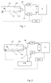
figure 1 shows a diagram of an embodiment of the system according to the invention; -
figure 2 shows another preferred variant of the invention. - In the figures, the same numbers and the same reference letters indicate the same elements or components.
- For the purposes of the invention, the term "second" component does not imply the presence of a "first" component. As a matter of fact, these terms are only used for greater clarity and should not be interpreted in a limiting manner.
- With reference to
figure 1 , a reservoir TK for compressed natural gas comprises a high opening HO and a low opening LO, so as to allow the gaseous phase GF and the liquid or condensed phase LF to be withdrawn from the reservoir TK separately and independently. - A first duct GP establishes a communication between said high opening HO and injection means J cooperating with an internal combustion engine E.
- A second duct LP establishes a communication between said low opening LO and said injection means J cooperating with an internal combustion engine E.
- On the first duct GP there is arranged a pressure reduction device PR, which is adapted to adapt the pressure of the gaseous phase to a predefined injection pressure. Similarly, on the second duct LP there is arranged a vaporisation device VP, which is adapted to gasify the withdrawn condensed phase LP, so as to obtain a predefined output pressure, which is adequate for the injection into the cylinders of the internal combustion engine.
- It should be pointed out that, in case of use of methane, the gaseous phase has a completely different nature compared to the liquid phase, since, whereas the gaseous phase relates to a non-condensable chemical composition, the liquid phase relates to a condensable mixture of compositions, which is completely different from the first one.
- A processing unit, for example the engine control unit ECU, controls the withdrawing of the liquid and gaseous phases and the injection means J.
- All methane-powered systems usually comprise a pressure sensor, which can be used to estimate the level of filling of the methane reservoir TK.
- According to a first preferred embodiment of the invention, the processing unit ECU is adapted to store the measured pressure levels and to acknowledge the refuelling event based on the measurement of the pressure measured in the reservoir TK.
- Starting from that moment, for a predefined consumption of fuel, the processing unit prefers the consumption of the liquid phase, withdrawing it separately from the gaseous phase. "Preferring" means that it is used in a privileged manner, according to the operating conditions of the engine, or that it is used changing the settings of the internal combustion engines, or both.
- Hence, this liquid phase can be injected into the cylinders in the liquid phase or it can be gasified, together with the substantially pure methane withdrawn from the high opening HO of the reservoir TK.
- When the processing unit ECU estimates that the liquid phase has ended, then the process goes on with the withdrawing of fuel from the sole high opening HO. According to a preferred embodiment, which can be combined with the previous one, the mixing of the methane and propane/ethane portions is a function of the operating point of the engine, so as not to jeopardize the performances thereof.
- In other words, the two phases are withdrawn selectively and they are injected simultaneously into the engine, so as to obtain a desired octane number, which can be fixed or can can be a function of the operating point of the internal combustion engine.
- The two selectively withdrawn phases can be injected into the engine both through different injectors and through the same injectors. In the first case, the mixing takes place in the cylinders, for example to obtain a stratified injection, whereas, in the second case, the mixing of the two phases takes place before the subsequent injection into the cylinders.
- According to another preferred embodiment of the invention, which can be combined with the previous ones, the operating parameters of the internal combustion engine are a function of the mixing of the methane and propane/ethane portions. Furthermore, both the fuel mixture and the operating parameters of the engine can be properly controlled. According to a preferred embodiment, which can be combined with the previous ones, a sensor S is arranged inside the reservoir TK to constantly measure the volume of the condensed fraction.
- Thanks to this solution, one can avoid estimating the consumption of the liquid phase through the injection means, thus obtaining a direct measurement of the propane/ethane fraction stored in the reservoir TK.
- It should be pointed out that
figure 1 does not show valves and it looks like the control of the withdrawing is directly operated upon the pressure reduction device PR or upon the vaporisation device VP, but this is only a representation simplification. Therefore, further control valves, non-return valves and safety valves can be provided. -
Figure 2 describes a further variant of the invention, in which a second reservoir ATK is connected to the second duct LP between the low opening LO and the vaporisation device VP. - Thanks to this second reservoir, which can be defined as an auxiliary reservoir, the liquid phase can be transferred from the methane reservoir TK immediately after the refuelling.
- Therefore, it can be used even when the pressure inside the methane reservoir TK has drastically decreased, without risking the gasification of the propane and butane fractions in the methane reservoir TK.
- The liquid phase sensor S, arranged in the methane reservoir TK, is, as already mentioned above, optional. When it is not present, 1 - 2% by volume of the methane reservoir TK can be transferred into the auxiliary reservoir ATK, withdrawing from the low part LO thereof, immediately after a refuelling.
- Said sensor S can be, for example, a float.
- When, on the other hand, there is a sensor S adapted to measure a liquid phase volume contained in the methane reservoir TK, the transferring operation can be controlled based on the measurement of said sensor S.
- The presence of the second reservoir, intended to substantially store propane and ethane, turns out to be very advantageous, since it can be filled independently of the methane reservoir, when there is no methane filling station available, but you can only find a LPG filling station.
- According to a further preferred embodiment of the invention, which can be combined with the previous ones, the engine processing unit, besides controlling the mixing of methane, propane and butane, can also adapt operating parameters of the internal combustion engine, so as to better adjust its behaviour to the injected mixture.
- The operating parameters of the engine can be, by mere way of example, the injection times, the mixture ignition times, the opening and closing angles of the valves, if they are adjustable, and the intervention of a wastegate valve, in case of a supercharged internal combustion engine.
- When adapting said operating parameters of the engine, the ECU can take into account, besides the load of the engine, i.e. the operating point of the engine, the temperature of the air taken in and the temperature of the cooling water, so as to control the percentages of the two species, namely methane and propane/ethane.
- It should be pointed out that models are known, which describe the inclination to knocking of the fuel based on the operating parameters and on the features of the engine, and, therefore, that knocking indexes of the internal combustion are known, which can be calculated by the ECU and take into account the aforesaid operating parameters and the features of the internal combustion engine. Therefore, the fuel mixture can be adapted in real time to the operating parameters of the engine, so as to avoid the self-knocking of the fuel.
- Alternatively, a knock sensor can be implemented and used to control the methane and propane/ethane mixture injected. Among the possible mixing ratios, it is also possible to inject substantially pure methane or LPG, which means propane/ethane with a very small percentage of methane.
- The octane number of the two fractions is different when there is a completely different chemical composition of the two fractions and this fact is different compared to trying to influence the octane request of the engine exploiting the latent evaporation heat of the liquid phase. This scenario is completely different from the one described, for example, in
US2015053180 orUS2001003977 , where the only fuel in the two phases, i.e. the liquid phase and the gaseous phase, is propane or butane (LPG). As a matter of fact, this fuel, despite being a mixture of two different components, does not substantially differ, in its composition, in the liquid phase and in the gaseous phase. Therefore, the gaseous phase and the liquid phase substantially have the same octane number, but the injection of the liquid phase, as it leads to an evaporation in the supply air, can reduce the temperature of the charge, thus reducing the octane request of the engine. It basically is an attempt to influence the octane request of the engine so that it can work well in different circumstances with a fuel with an octane number that is fixed and known in advance. - On the contrary, the object of the invention is to separate two fractions, clearly different from one another both from the point of view of the physical state (liquid/gaseous) and from the point of view of the octane number, and to adapt the octane quality of the fuel mixture to the request of the engine.
- Typical conditions that allow the engine to operate with a fuel having a reduced octane number are:
- 1) Idle
- 2) Driving conditions with a load below a predetermined percentage (i.e. 35%)
- 3) Conditions of very cold air taken in and/or engine water still cold
- 4) Conditions of dragged engine, wherein the injection of fuel is necessary so as not to cool the ATS (After Treatment System).
- The ATS generally comprises at least one three-way catalytic converter.
- The ECU can be properly programmed to selectively withdraw the two fractions and mix them when they are both available and/or to prefer the liquid fraction in the aforesaid four operating conditions. However, in case the methane reservoir TK is empty and, on the other hand, the second reservoir is full, possibly because of the sole presence of LPG filling stations, the ECU can also be programmed to change the operating parameters of the engine mentioned above, so as to adapt to this type of fuel.
- The engine ECU, in this conditions, carries out an adjustment (limitation) of the performances for the operation with this fuel with a reduced octane number. According to a preferred embodiment of the invention, the internal combustion engine E can be provided with one single injection system E for the gas alternatively supplied by the methane pressure reduction device PR or by the condensed fraction vaporisation device VP or by both. Therefore, both the pressure reduction device and the vaporisation device preferably have the same output pressure, preferably 4 bar.
- Alternatively, an injection system can be provided, which is separate fro the condensed fraction and the methane.
- It should be pointed out that, in the figures, the cylinder TK is shown with its development axis arranged in a horizontal position, as this is how cylinders are normally arranged on board vehicles, but this does not exclude the fact that it can be oriented in any other way; what matters is that there are a high opening for withdrawing a gaseous fraction and a low opening for withdrawing a liquid fraction.
- According to this embodiment, the condensed fraction can be injected in a liquid phase, i.e. without the use of a vaporisation device VP, into the intake manifolds. This second operating mode has the advantage of reducing the temperature of the air taken in with the evaporation of the fuel, thus reducing the octane request of the engine and, consequently, the gap of performances that can be delivered with the liquid fuel. This embodiment, which is not shown in the figures, is equivalent to not having a vaporisation device VP and having two separate injection systems J (and J').
- This invention can be advantageously implemented by means of a computer program comprising coding means for carrying out one or more steps of the method, when the program is executed by a computer. Therefore, the scope of protection is extended to said computer program and, furthermore, to means that can be read by a computer and comprises a recorded message, said means that can be read by a computer comprising coding means for a program for carrying out one or more steps of the method, when the program is executed by a computer.
- The non-limiting example described above can be subjected to variations, without for this reason going beyond the scope of protection of the invention, comprising all equivalent embodiments for a person skilled in the art.
- When reading the description above, a skilled person can carry out the subject-matter of the invention without introducing further manufacturing details. The elements and features contained in the different preferred embodiments, drawings included, can be combined with one another, without for this reason going beyond the scope of protection of this patent application. The information contained in the part concerning the state of art only serves the purpose of better understanding the invention and does nor represent a declaration of existence of the items described. Furthermore, if not specifically excluded by the detailed description, the information contained in the part concerning the state of art can be considered as combined with the features of the invention, thus forming an integral part of the invention. None of the features of the different variants is essential and, therefore, the single features of each preferred variant or drawing can be individually combined with the other variants.
Claims (17)
- Fuel withdrawing system from a reservoir (TK) of compressed natural gas to supply an internal combustion (E) engine (E), the system comprising means ((HO, GP, PR), (LO, LP, VP)) for selectively withdrawing a non-condensable gaseous fraction (GF), substantially pure methane, and a condensed fraction (LF), substantially liquid propane and ethylene.
- System according to claim 1, further comprising means (S) for measuring a condensed fraction (LF) in said reservoir (TK) and/or means (ECU) for estimating the presence of a condensed fraction (LF), by detection of a refuelling procedure of the reservoir (TK), and for continuously estimating a relative presence on the basis of an effective withdrawal of said gaseous fraction (GF) and/or condensed fraction (LF).
- System according to one of the preceding claims, further comprising a processing unit (ECU) adapted to control said selective withdrawal so as to supply said condensed fraction (LF), simultaneously with said gaseous fraction GF, to said internal combustion engine (E) according to a predefined desired value of the octane number of the overall fuel mixture, taking into account that said condensed fraction and said gaseous fraction have different octane numbers.
- System according to claim 3, wherein said processing unit is configured to adapt said octane number according to one or more operating conditions of the internal combustion engine (E).
- System according to claim 4, wherein said one or more operating conditions comprise:- an engine point or load below a predefined threshold,- a temperature of an intake air below a second predefined threshold,- a temperature of a cooling fluid of the internal combustion engine below a third predefined threshold,- a condition in which the internal combustion engine (E) is dragged, wherein an injection of fuel is necessary so as not to cool a relative ATS (After Treatment System).
- System according to claim 5, wherein said operating parameters of said internal combustion engine (E) comprise at least one of:- injection times,- mixture ignition times,- opening and closing angles of intake and/or exhaust valves- intervention of a wastegate valve.
- System according to any one of the preceding claims, wherein said withdrawal means ((HO, GP, PR), (LO, LP, VP)) comprise a high opening (HO) arranged in an upper part of said reservoir (TK) and a relative first duct (GP) adapted to connect said high opening (HO) to first injection means (J) by means of a pressure reduction device(PR).
- System according to any one of the preceding claims, wherein said withdrawal means ((HO, GP, PR), (LO, LP, VP)) comprise a low opening (LO) arranged in a lower part of said reservoir (TK) and a relative second duct (LP) adapted to connect said low opening (LO) to said first injection means (J) via a vaporisation device (VP).
- System according to any one of the preceding claims from 1 to 7, wherein said withdrawal means ((HO, GP, PR), (LO, LP, VP)) comprise a low opening (LO) arranged in a lower part of said reservoir (TK) and a relative second duct (LP) adapted to connect said low opening (LO) to second injection means.
- System according to claim 9, wherein said second injection means are adapted to perform a liquid injection of said condensed fraction (LF) into the internal combustion engine (E).
- System according to any one of the preceding claims from 2 to 10, further comprising a second reservoir (ATK) intended to store said condensed fraction (LF), arranged on said second duct (LP), and comprising automatic transfer means (S, ECU) adapted to control an automatic transfer of said condensed fraction (LF) into said second reservoir, so as to avoid gasification of said condensed fraction as said natural gas reservoir (TK) empties.
- Terrestrial vehicle comprising an internal combustion engine (E) and a natural gas reservoir (TK) to supply said internal combustion engine and comprising a withdrawal system according to any one of the claims from 1 to 11.
- Method for withdrawing fuel from a reservoir (TK) of compressed natural gas to supply an internal combustion (E) engine (E), the method comprising a step of selectively withdrawing a gaseous fraction (GF), substantially non-condensable pure methane, and a condensed fraction (LF), substantially liquid propane and ethylene.
- Method according to claim 13, further comprising a step of selecting or mixing said gaseous fraction (GF) and condensed fraction (LF) to supply said internal combustion engine according to a predefined octane number.
- Method according to claim 14, further comprising a step of adapting said octane number according to one or more operating conditions of the internal combustion engine (E) and/or a step of adapting at least one of said operating parameters according to said octane number obtained.
- Method according to claim 15, wherein said one or more operating conditions comprise:- an engine point or load below a predefined threshold,- a temperature of an intake air below a second predefined threshold,- a temperature of a cooling fluid of the internal combustion engine below a third predefined threshold,- a condition in which the internal combustion engine (E) is dragged, wherein an injection of fuel is necessary so as not to cool a relative ATS (After Treatment System).
- Method according to any of the preceding claims from 13 to 15, further comprising a preliminary step of estimating or measuring a volume of said condensed fraction (LF) and/or a preliminary step of estimating or measuring a volume of said condensed fraction (LF) and transferring said condensed fraction into a second reservoir (ATK).
Applications Claiming Priority (1)
| Application Number | Priority Date | Filing Date | Title |
|---|---|---|---|
| ITTO20150213 | 2015-04-13 |
Publications (2)
| Publication Number | Publication Date |
|---|---|
| EP3081800A1 true EP3081800A1 (en) | 2016-10-19 |
| EP3081800B1 EP3081800B1 (en) | 2019-06-05 |
Family
ID=53442885
Family Applications (1)
| Application Number | Title | Priority Date | Filing Date |
|---|---|---|---|
| EP16165006.4A Active EP3081800B1 (en) | 2015-04-13 | 2016-04-13 | Fuel withdrawing system from a reservoir of compressed natural gas to supply an internal combustion engine |
Country Status (2)
| Country | Link |
|---|---|
| EP (1) | EP3081800B1 (en) |
| ES (1) | ES2741558T3 (en) |
Cited By (2)
| Publication number | Priority date | Publication date | Assignee | Title |
|---|---|---|---|---|
| WO2017222440A1 (en) * | 2016-06-21 | 2017-12-28 | Scania Cv Ab | A method and a system for controlling a gas engine |
| WO2018236263A1 (en) * | 2017-06-22 | 2018-12-27 | Scania Cv Ab | SYSTEM AND METHOD FOR DETERMINING COMBUSTION PROPERTIES OF A COMBUSTIBLE GAS |
Citations (6)
| Publication number | Priority date | Publication date | Assignee | Title |
|---|---|---|---|---|
| US5697346A (en) * | 1993-05-28 | 1997-12-16 | Servojet Products International | Method for using sonic gas-fueled internal combustion engine control system |
| US20010003977A1 (en) | 1999-12-13 | 2001-06-21 | Kenji Hayashi | Fuel injection system for internal combustion engines and its method of control |
| US20090088983A1 (en) * | 2006-05-12 | 2009-04-02 | Erwin Bauer | Method and device for determining the composition of a gas mixture of a fuel tank of a motor vehicle filled with cng |
| US20110226362A1 (en) * | 2006-08-21 | 2011-09-22 | Nmhg Oregon, Llc | Auxiliary fuel tank |
| WO2013181753A1 (en) * | 2012-06-05 | 2013-12-12 | Westport Power Inc. | Supplying gaseous fuel from a liquid state to an internal combustion engine |
| US20150053180A1 (en) | 2013-08-22 | 2015-02-26 | Ford Global Technologies, Llc | Method and system for gaseous and liquid fuel injection |
-
2016
- 2016-04-13 ES ES16165006T patent/ES2741558T3/en active Active
- 2016-04-13 EP EP16165006.4A patent/EP3081800B1/en active Active
Patent Citations (6)
| Publication number | Priority date | Publication date | Assignee | Title |
|---|---|---|---|---|
| US5697346A (en) * | 1993-05-28 | 1997-12-16 | Servojet Products International | Method for using sonic gas-fueled internal combustion engine control system |
| US20010003977A1 (en) | 1999-12-13 | 2001-06-21 | Kenji Hayashi | Fuel injection system for internal combustion engines and its method of control |
| US20090088983A1 (en) * | 2006-05-12 | 2009-04-02 | Erwin Bauer | Method and device for determining the composition of a gas mixture of a fuel tank of a motor vehicle filled with cng |
| US20110226362A1 (en) * | 2006-08-21 | 2011-09-22 | Nmhg Oregon, Llc | Auxiliary fuel tank |
| WO2013181753A1 (en) * | 2012-06-05 | 2013-12-12 | Westport Power Inc. | Supplying gaseous fuel from a liquid state to an internal combustion engine |
| US20150053180A1 (en) | 2013-08-22 | 2015-02-26 | Ford Global Technologies, Llc | Method and system for gaseous and liquid fuel injection |
Cited By (6)
| Publication number | Priority date | Publication date | Assignee | Title |
|---|---|---|---|---|
| WO2017222440A1 (en) * | 2016-06-21 | 2017-12-28 | Scania Cv Ab | A method and a system for controlling a gas engine |
| KR20190017037A (en) * | 2016-06-21 | 2019-02-19 | 스카니아 씨브이 악티에볼라그 | Method and system for controlling a gas engine |
| WO2018236263A1 (en) * | 2017-06-22 | 2018-12-27 | Scania Cv Ab | SYSTEM AND METHOD FOR DETERMINING COMBUSTION PROPERTIES OF A COMBUSTIBLE GAS |
| SE541107C2 (en) * | 2017-06-22 | 2019-04-09 | Scania Cv Ab | System and method for determining combustion properties of a fuel gas |
| CN110770424A (en) * | 2017-06-22 | 2020-02-07 | 斯堪尼亚商用车有限公司 | System and method for determining combustion characteristics of fuel gas |
| EP3642466A4 (en) * | 2017-06-22 | 2021-03-10 | Scania CV AB | System and method for determining combustion properties of a fuel gas |
Also Published As
| Publication number | Publication date |
|---|---|
| EP3081800B1 (en) | 2019-06-05 |
| ES2741558T3 (en) | 2020-02-11 |
Similar Documents
| Publication | Publication Date | Title |
|---|---|---|
| CN104564393B (en) | Strategies for the use of vehicles fuelled with gasoline and CNG blends | |
| RU2666032C2 (en) | Method for engine (options) and fuel system of engine | |
| US7690336B2 (en) | Adaptive miller cycle engine | |
| US9909514B2 (en) | Direct injection of diluents or secondary fuels in gaseous fuel engines | |
| CN105089826B (en) | System and method for improving operation of a highly diluted engine | |
| US9528472B2 (en) | Enhanced fuel injection based on choke flow rate | |
| RU152742U1 (en) | ENGINE SYSTEM | |
| CN109630300B (en) | Method and system for cylinder imbalance estimation | |
| RU2653644C2 (en) | Refueling systems for mixed liquid and gaseous fuel | |
| RU2680449C2 (en) | Refueling methods, system for liquid fuel and gas fuel supply to internal combustion engine and method | |
| EP2179161A2 (en) | Cetane number detection device and cetane number detection method | |
| KR20170113569A (en) | Injection device for internal combustion engine | |
| US9664125B2 (en) | Method and system for transient fuel control | |
| CN102597465B (en) | The control gear of internal-combustion engine | |
| US10006380B2 (en) | Control device for internal combustion engine | |
| EP3081800B1 (en) | Fuel withdrawing system from a reservoir of compressed natural gas to supply an internal combustion engine | |
| US20200056566A1 (en) | Method and Device for Increasing the Global Compression Ratio of an Internal Combustion Engine in the Case of Varying Fuel Quality | |
| JP2011214568A (en) | Device for control of internal combustion engine | |
| KR101536365B1 (en) | Starting performance improving system in lpg engine | |
| KR102726880B1 (en) | Apparatus and method for supplying liquefied petroleum gas | |
| JP2014190311A (en) | Fuel injection control device for bi-fuel internal combustion engine |
Legal Events
| Date | Code | Title | Description |
|---|---|---|---|
| PUAI | Public reference made under article 153(3) epc to a published international application that has entered the european phase |
Free format text: ORIGINAL CODE: 0009012 |
|
| AK | Designated contracting states |
Kind code of ref document: A1 Designated state(s): AL AT BE BG CH CY CZ DE DK EE ES FI FR GB GR HR HU IE IS IT LI LT LU LV MC MK MT NL NO PL PT RO RS SE SI SK SM TR |
|
| AX | Request for extension of the european patent |
Extension state: BA ME |
|
| STAA | Information on the status of an ep patent application or granted ep patent |
Free format text: STATUS: REQUEST FOR EXAMINATION WAS MADE |
|
| 17P | Request for examination filed |
Effective date: 20170419 |
|
| RBV | Designated contracting states (corrected) |
Designated state(s): AL AT BE BG CH CY CZ DE DK EE ES FI FR GB GR HR HU IE IS IT LI LT LU LV MC MK MT NL NO PL PT RO RS SE SI SK SM TR |
|
| STAA | Information on the status of an ep patent application or granted ep patent |
Free format text: STATUS: EXAMINATION IS IN PROGRESS |
|
| 17Q | First examination report despatched |
Effective date: 20170921 |
|
| GRAP | Despatch of communication of intention to grant a patent |
Free format text: ORIGINAL CODE: EPIDOSNIGR1 |
|
| STAA | Information on the status of an ep patent application or granted ep patent |
Free format text: STATUS: GRANT OF PATENT IS INTENDED |
|
| INTG | Intention to grant announced |
Effective date: 20181219 |
|
| GRAS | Grant fee paid |
Free format text: ORIGINAL CODE: EPIDOSNIGR3 |
|
| GRAA | (expected) grant |
Free format text: ORIGINAL CODE: 0009210 |
|
| STAA | Information on the status of an ep patent application or granted ep patent |
Free format text: STATUS: THE PATENT HAS BEEN GRANTED |
|
| AK | Designated contracting states |
Kind code of ref document: B1 Designated state(s): AL AT BE BG CH CY CZ DE DK EE ES FI FR GB GR HR HU IE IS IT LI LT LU LV MC MK MT NL NO PL PT RO RS SE SI SK SM TR |
|
| REG | Reference to a national code |
Ref country code: GB Ref legal event code: FG4D |
|
| REG | Reference to a national code |
Ref country code: CH Ref legal event code: EP |
|
| REG | Reference to a national code |
Ref country code: AT Ref legal event code: REF Ref document number: 1140231 Country of ref document: AT Kind code of ref document: T Effective date: 20190615 |
|
| REG | Reference to a national code |
Ref country code: IE Ref legal event code: FG4D |
|
| REG | Reference to a national code |
Ref country code: DE Ref legal event code: R096 Ref document number: 602016014695 Country of ref document: DE |
|
| REG | Reference to a national code |
Ref country code: NL Ref legal event code: FP |
|
| REG | Reference to a national code |
Ref country code: SE Ref legal event code: TRGR |
|
| REG | Reference to a national code |
Ref country code: LT Ref legal event code: MG4D |
|
| PG25 | Lapsed in a contracting state [announced via postgrant information from national office to epo] |
Ref country code: LT Free format text: LAPSE BECAUSE OF FAILURE TO SUBMIT A TRANSLATION OF THE DESCRIPTION OR TO PAY THE FEE WITHIN THE PRESCRIBED TIME-LIMIT Effective date: 20190605 Ref country code: HR Free format text: LAPSE BECAUSE OF FAILURE TO SUBMIT A TRANSLATION OF THE DESCRIPTION OR TO PAY THE FEE WITHIN THE PRESCRIBED TIME-LIMIT Effective date: 20190605 Ref country code: NO Free format text: LAPSE BECAUSE OF FAILURE TO SUBMIT A TRANSLATION OF THE DESCRIPTION OR TO PAY THE FEE WITHIN THE PRESCRIBED TIME-LIMIT Effective date: 20190905 Ref country code: FI Free format text: LAPSE BECAUSE OF FAILURE TO SUBMIT A TRANSLATION OF THE DESCRIPTION OR TO PAY THE FEE WITHIN THE PRESCRIBED TIME-LIMIT Effective date: 20190605 Ref country code: AL Free format text: LAPSE BECAUSE OF FAILURE TO SUBMIT A TRANSLATION OF THE DESCRIPTION OR TO PAY THE FEE WITHIN THE PRESCRIBED TIME-LIMIT Effective date: 20190605 |
|
| PG25 | Lapsed in a contracting state [announced via postgrant information from national office to epo] |
Ref country code: BG Free format text: LAPSE BECAUSE OF FAILURE TO SUBMIT A TRANSLATION OF THE DESCRIPTION OR TO PAY THE FEE WITHIN THE PRESCRIBED TIME-LIMIT Effective date: 20190905 Ref country code: LV Free format text: LAPSE BECAUSE OF FAILURE TO SUBMIT A TRANSLATION OF THE DESCRIPTION OR TO PAY THE FEE WITHIN THE PRESCRIBED TIME-LIMIT Effective date: 20190605 Ref country code: RS Free format text: LAPSE BECAUSE OF FAILURE TO SUBMIT A TRANSLATION OF THE DESCRIPTION OR TO PAY THE FEE WITHIN THE PRESCRIBED TIME-LIMIT Effective date: 20190605 Ref country code: GR Free format text: LAPSE BECAUSE OF FAILURE TO SUBMIT A TRANSLATION OF THE DESCRIPTION OR TO PAY THE FEE WITHIN THE PRESCRIBED TIME-LIMIT Effective date: 20190906 |
|
| REG | Reference to a national code |
Ref country code: AT Ref legal event code: MK05 Ref document number: 1140231 Country of ref document: AT Kind code of ref document: T Effective date: 20190605 |
|
| PG25 | Lapsed in a contracting state [announced via postgrant information from national office to epo] |
Ref country code: RO Free format text: LAPSE BECAUSE OF FAILURE TO SUBMIT A TRANSLATION OF THE DESCRIPTION OR TO PAY THE FEE WITHIN THE PRESCRIBED TIME-LIMIT Effective date: 20190605 Ref country code: AT Free format text: LAPSE BECAUSE OF FAILURE TO SUBMIT A TRANSLATION OF THE DESCRIPTION OR TO PAY THE FEE WITHIN THE PRESCRIBED TIME-LIMIT Effective date: 20190605 Ref country code: EE Free format text: LAPSE BECAUSE OF FAILURE TO SUBMIT A TRANSLATION OF THE DESCRIPTION OR TO PAY THE FEE WITHIN THE PRESCRIBED TIME-LIMIT Effective date: 20190605 Ref country code: PT Free format text: LAPSE BECAUSE OF FAILURE TO SUBMIT A TRANSLATION OF THE DESCRIPTION OR TO PAY THE FEE WITHIN THE PRESCRIBED TIME-LIMIT Effective date: 20191007 Ref country code: CZ Free format text: LAPSE BECAUSE OF FAILURE TO SUBMIT A TRANSLATION OF THE DESCRIPTION OR TO PAY THE FEE WITHIN THE PRESCRIBED TIME-LIMIT Effective date: 20190605 Ref country code: SK Free format text: LAPSE BECAUSE OF FAILURE TO SUBMIT A TRANSLATION OF THE DESCRIPTION OR TO PAY THE FEE WITHIN THE PRESCRIBED TIME-LIMIT Effective date: 20190605 |
|
| REG | Reference to a national code |
Ref country code: ES Ref legal event code: FG2A Ref document number: 2741558 Country of ref document: ES Kind code of ref document: T3 Effective date: 20200211 |
|
| PG25 | Lapsed in a contracting state [announced via postgrant information from national office to epo] |
Ref country code: SM Free format text: LAPSE BECAUSE OF FAILURE TO SUBMIT A TRANSLATION OF THE DESCRIPTION OR TO PAY THE FEE WITHIN THE PRESCRIBED TIME-LIMIT Effective date: 20190605 Ref country code: IS Free format text: LAPSE BECAUSE OF FAILURE TO SUBMIT A TRANSLATION OF THE DESCRIPTION OR TO PAY THE FEE WITHIN THE PRESCRIBED TIME-LIMIT Effective date: 20191005 |
|
| REG | Reference to a national code |
Ref country code: DE Ref legal event code: R097 Ref document number: 602016014695 Country of ref document: DE |
|
| PG25 | Lapsed in a contracting state [announced via postgrant information from national office to epo] |
Ref country code: TR Free format text: LAPSE BECAUSE OF FAILURE TO SUBMIT A TRANSLATION OF THE DESCRIPTION OR TO PAY THE FEE WITHIN THE PRESCRIBED TIME-LIMIT Effective date: 20190605 |
|
| PLBE | No opposition filed within time limit |
Free format text: ORIGINAL CODE: 0009261 |
|
| STAA | Information on the status of an ep patent application or granted ep patent |
Free format text: STATUS: NO OPPOSITION FILED WITHIN TIME LIMIT |
|
| PG25 | Lapsed in a contracting state [announced via postgrant information from national office to epo] |
Ref country code: DK Free format text: LAPSE BECAUSE OF FAILURE TO SUBMIT A TRANSLATION OF THE DESCRIPTION OR TO PAY THE FEE WITHIN THE PRESCRIBED TIME-LIMIT Effective date: 20190605 Ref country code: PL Free format text: LAPSE BECAUSE OF FAILURE TO SUBMIT A TRANSLATION OF THE DESCRIPTION OR TO PAY THE FEE WITHIN THE PRESCRIBED TIME-LIMIT Effective date: 20190605 |
|
| 26N | No opposition filed |
Effective date: 20200306 |
|
| PG25 | Lapsed in a contracting state [announced via postgrant information from national office to epo] |
Ref country code: SI Free format text: LAPSE BECAUSE OF FAILURE TO SUBMIT A TRANSLATION OF THE DESCRIPTION OR TO PAY THE FEE WITHIN THE PRESCRIBED TIME-LIMIT Effective date: 20190605 |
|
| PG25 | Lapsed in a contracting state [announced via postgrant information from national office to epo] |
Ref country code: MC Free format text: LAPSE BECAUSE OF FAILURE TO SUBMIT A TRANSLATION OF THE DESCRIPTION OR TO PAY THE FEE WITHIN THE PRESCRIBED TIME-LIMIT Effective date: 20190605 |
|
| REG | Reference to a national code |
Ref country code: CH Ref legal event code: PL |
|
| PG25 | Lapsed in a contracting state [announced via postgrant information from national office to epo] |
Ref country code: LU Free format text: LAPSE BECAUSE OF NON-PAYMENT OF DUE FEES Effective date: 20200413 Ref country code: CH Free format text: LAPSE BECAUSE OF NON-PAYMENT OF DUE FEES Effective date: 20200430 Ref country code: LI Free format text: LAPSE BECAUSE OF NON-PAYMENT OF DUE FEES Effective date: 20200430 |
|
| REG | Reference to a national code |
Ref country code: BE Ref legal event code: MM Effective date: 20200430 |
|
| PG25 | Lapsed in a contracting state [announced via postgrant information from national office to epo] |
Ref country code: BE Free format text: LAPSE BECAUSE OF NON-PAYMENT OF DUE FEES Effective date: 20200430 |
|
| PG25 | Lapsed in a contracting state [announced via postgrant information from national office to epo] |
Ref country code: IE Free format text: LAPSE BECAUSE OF NON-PAYMENT OF DUE FEES Effective date: 20200413 |
|
| PG25 | Lapsed in a contracting state [announced via postgrant information from national office to epo] |
Ref country code: MT Free format text: LAPSE BECAUSE OF FAILURE TO SUBMIT A TRANSLATION OF THE DESCRIPTION OR TO PAY THE FEE WITHIN THE PRESCRIBED TIME-LIMIT Effective date: 20190605 Ref country code: CY Free format text: LAPSE BECAUSE OF FAILURE TO SUBMIT A TRANSLATION OF THE DESCRIPTION OR TO PAY THE FEE WITHIN THE PRESCRIBED TIME-LIMIT Effective date: 20190605 |
|
| PG25 | Lapsed in a contracting state [announced via postgrant information from national office to epo] |
Ref country code: MK Free format text: LAPSE BECAUSE OF FAILURE TO SUBMIT A TRANSLATION OF THE DESCRIPTION OR TO PAY THE FEE WITHIN THE PRESCRIBED TIME-LIMIT Effective date: 20190605 |
|
| P01 | Opt-out of the competence of the unified patent court (upc) registered |
Effective date: 20230523 |
|
| PGFP | Annual fee paid to national office [announced via postgrant information from national office to epo] |
Ref country code: SE Payment date: 20250228 Year of fee payment: 10 |
|
| PGFP | Annual fee paid to national office [announced via postgrant information from national office to epo] |
Ref country code: NL Payment date: 20250424 Year of fee payment: 10 |
|
| PGFP | Annual fee paid to national office [announced via postgrant information from national office to epo] |
Ref country code: DE Payment date: 20250428 Year of fee payment: 10 |
|
| PGFP | Annual fee paid to national office [announced via postgrant information from national office to epo] |
Ref country code: ES Payment date: 20250513 Year of fee payment: 10 |
|
| PGFP | Annual fee paid to national office [announced via postgrant information from national office to epo] |
Ref country code: IT Payment date: 20250408 Year of fee payment: 10 |
|
| PGFP | Annual fee paid to national office [announced via postgrant information from national office to epo] |
Ref country code: FR Payment date: 20250424 Year of fee payment: 10 |
|
| PGFP | Annual fee paid to national office [announced via postgrant information from national office to epo] |
Ref country code: GB Payment date: 20260304 Year of fee payment: 11 |