EP3081693A1 - A method of producing lids from cellulose fibers for containers - Google Patents
A method of producing lids from cellulose fibers for containers Download PDFInfo
- Publication number
- EP3081693A1 EP3081693A1 EP15001100.5A EP15001100A EP3081693A1 EP 3081693 A1 EP3081693 A1 EP 3081693A1 EP 15001100 A EP15001100 A EP 15001100A EP 3081693 A1 EP3081693 A1 EP 3081693A1
- Authority
- EP
- European Patent Office
- Prior art keywords
- cavities
- deformable material
- blow mould
- shape
- mould
- Prior art date
- Legal status (The legal status is an assumption and is not a legal conclusion. Google has not performed a legal analysis and makes no representation as to the accuracy of the status listed.)
- Withdrawn
Links
- 229920003043 Cellulose fiber Polymers 0.000 title claims abstract description 60
- 238000000034 method Methods 0.000 title claims abstract description 28
- 239000000463 material Substances 0.000 claims abstract description 77
- 238000009423 ventilation Methods 0.000 claims abstract description 22
- 238000003825 pressing Methods 0.000 claims abstract description 8
- 241000609240 Ambelania acida Species 0.000 claims description 12
- 239000010905 bagasse Substances 0.000 claims description 12
- 238000000465 moulding Methods 0.000 claims description 10
- PNEYBMLMFCGWSK-UHFFFAOYSA-N Alumina Chemical compound [O-2].[O-2].[O-2].[Al+3].[Al+3] PNEYBMLMFCGWSK-UHFFFAOYSA-N 0.000 claims description 9
- 241000196324 Embryophyta Species 0.000 claims description 7
- 240000000111 Saccharum officinarum Species 0.000 claims description 7
- 235000007201 Saccharum officinarum Nutrition 0.000 claims description 7
- 229920002678 cellulose Polymers 0.000 claims description 7
- 239000001913 cellulose Substances 0.000 claims description 7
- 239000000835 fiber Substances 0.000 claims description 5
- VYPSYNLAJGMNEJ-UHFFFAOYSA-N Silicium dioxide Chemical compound O=[Si]=O VYPSYNLAJGMNEJ-UHFFFAOYSA-N 0.000 claims description 4
- 229910052814 silicon oxide Inorganic materials 0.000 claims description 4
- XUIMIQQOPSSXEZ-UHFFFAOYSA-N Silicon Chemical compound [Si] XUIMIQQOPSSXEZ-UHFFFAOYSA-N 0.000 claims description 3
- 238000000151 deposition Methods 0.000 claims description 3
- 230000002093 peripheral effect Effects 0.000 claims description 3
- 229910052710 silicon Inorganic materials 0.000 claims description 3
- 239000010703 silicon Substances 0.000 claims description 3
- 238000007598 dipping method Methods 0.000 claims description 2
- 230000009969 flowable effect Effects 0.000 claims description 2
- 239000011159 matrix material Substances 0.000 claims description 2
- 239000000126 substance Substances 0.000 claims description 2
- 239000004033 plastic Substances 0.000 description 6
- 229920003023 plastic Polymers 0.000 description 6
- 238000004519 manufacturing process Methods 0.000 description 5
- 230000004888 barrier function Effects 0.000 description 3
- 238000001035 drying Methods 0.000 description 3
- 230000002349 favourable effect Effects 0.000 description 3
- 239000007788 liquid Substances 0.000 description 3
- 229910000831 Steel Inorganic materials 0.000 description 2
- 235000013361 beverage Nutrition 0.000 description 2
- 230000015572 biosynthetic process Effects 0.000 description 2
- 238000010586 diagram Methods 0.000 description 2
- 229920001971 elastomer Polymers 0.000 description 2
- 238000001704 evaporation Methods 0.000 description 2
- 230000008020 evaporation Effects 0.000 description 2
- 239000011521 glass Substances 0.000 description 2
- 239000004816 latex Substances 0.000 description 2
- 229920000126 latex Polymers 0.000 description 2
- 238000007789 sealing Methods 0.000 description 2
- 238000007493 shaping process Methods 0.000 description 2
- 239000010959 steel Substances 0.000 description 2
- -1 Polyethylene Polymers 0.000 description 1
- 239000004698 Polyethylene Substances 0.000 description 1
- 244000258044 Solanum gilo Species 0.000 description 1
- 244000269722 Thea sinensis Species 0.000 description 1
- 239000011248 coating agent Substances 0.000 description 1
- 238000000576 coating method Methods 0.000 description 1
- 230000001419 dependent effect Effects 0.000 description 1
- 235000011389 fruit/vegetable juice Nutrition 0.000 description 1
- 235000012171 hot beverage Nutrition 0.000 description 1
- 238000002955 isolation Methods 0.000 description 1
- 229920000573 polyethylene Polymers 0.000 description 1
- 238000003672 processing method Methods 0.000 description 1
- 239000011343 solid material Substances 0.000 description 1
- 238000007666 vacuum forming Methods 0.000 description 1
- 239000002699 waste material Substances 0.000 description 1
Images



Classifications
-
- D—TEXTILES; PAPER
- D21—PAPER-MAKING; PRODUCTION OF CELLULOSE
- D21J—FIBREBOARD; MANUFACTURE OF ARTICLES FROM CELLULOSIC FIBROUS SUSPENSIONS OR FROM PAPIER-MACHE
- D21J3/00—Manufacture of articles by pressing wet fibre pulp, or papier-mâché, between moulds
- D21J3/10—Manufacture of articles by pressing wet fibre pulp, or papier-mâché, between moulds of hollow bodies
-
- D—TEXTILES; PAPER
- D21—PAPER-MAKING; PRODUCTION OF CELLULOSE
- D21J—FIBREBOARD; MANUFACTURE OF ARTICLES FROM CELLULOSIC FIBROUS SUSPENSIONS OR FROM PAPIER-MACHE
- D21J7/00—Manufacture of hollow articles from fibre suspensions or papier-mâché by deposition of fibres in or on a wire-net mould
Definitions
- the present invention relates to a method and an apparatus for producing lids from cellulose fibers for containers.
- Lids for containers are well-known in the beverage container industry, e.g. most coffee shops in the world offer a take away service where a customer receives his coffee in a container, e.g. a paper cup, with a lid on top of the cup for sealing the opening of the container.
- a container e.g. a paper cup
- lids e.g. lids with movable closing flap as disclosed in US. Pat. No. 4,579,245 or a lid having a movable cover for the opening as disclosed in U.S. Pat. No. 4,790.444 .
- lids used today are single-use lids and are typically made of plastic material, where after use the lids are typically end up as a waste material.
- lids for containers that provide excellent sealing between the lids and the containers and that at the same time are fully recyclable and that may be produced at a mass production level.
- lids that have similar or the same appearance as prior art lids that are typically made of plastic material.
- the invention preferably seeks to mitigate, alleviate or eliminate one or more of the above mentioned disadvantages singly or in any combination.
- a method is provided of producing lids for containers from cellulose fibers, comprising:
- the deformable material will impact on the inner side of the cavities of the blow mould with such a pressure that the deformable material will press the wet moulded products at all the surface and surface spots/areas on the inner side of the cavities, such as all types of protrusions, boundaries etc.
- all kinds of shapes on the outside of the lids may be done produced, e.g. any types of outwardly protruding parts such as mounting portions on the side wall of the lids that connect the lid to the containers in a manner that seals the lid on the container can be produced almost instantly.
- the deformable material may be at a room temperature during this, i.e. there may be no need to heat it up to a higher temperature during the production of the disposable containers.
- the deformable material may also be pre-heated to a given operating temperature during this process.
- a single drying and shaping step is provided to produce the lids at a mass production level within few seconds time.
- the deformable material may be made of any type of material that preferably has high elasticity such as, but not limited to, latex, rubber, or any type of deformable plastic material having sufficient elasticity.
- the thickness of the deformable material may also be adapted to the type of products being produced, and may e.g. vary from being a millimeter or even less thick up to few millimeters thick.
- ventilation openings may be understood as any type access channels, access slits, or drainage channels for the moisture and/or the liquid in the wet moulded products, that may have any type of cross sectional shape, e.g. cylindrical, rectangular, elliptical etc. that interconnect the inside and the outside of the blow mould.
- the diameter of these ventilation holes/ventilation openings may have a dimension ranging from 1mm to micrometer range such as 50 ⁇ m.
- the cellulose fibers is a plant based cellulose.
- the plant based cellulose is bagasse produced from sugarcane. Bagasse is 100% biodegradable and compostable and a bi product of sugar cane fiber which is left after the juice has been extracted from the sugar cane, but hundred thousands of tons of bagasse remains to be used yearly.
- bagasse has become a very cheap product and thus the value of bagasse may be increased significantly and therefore a favorable option is provided for producing lids for containers using bagasse.
- bagasse is annually renewable as opposed to trees that take 7 top 20 years to grow and is biodegradable as trees.
- the lids will have at least the same strength as the lids being used today and similar if not the same appearance as lids that are e.g. made of plastic material.
- the wet moulded products have a geometry essentially following the geometry of the interior of the plurality of cavities of the blow mould. The risk that the wet moulded product comes apart during production is reduced because the wet moulded products can be sensitive. Therefore, the better they fit into the cavities the more reliable will the production be.
- the deformable material comprises plurality of lid like portions
- the step of placing the deformable material adjacent to the plurality of cavities of the blow mould includes placing the plurality of lid like portions of the deformable material at least partly into the plurality of cavities
- supplying the pressure on the deformable material into the shape of the plurality of cavities comprises supplying a pressure on the plurality of the lid like portions of the deformable material causing a simultaneous inflation of the lid like portions of the deformable material into the plurality of cavities of the blow mould.
- the lid like portions may in one embodiment have a geometrical shape essentially following the geometry of the interior of the plurality of cavities of the blow mould.
- each of the plurality of cavities comprise two or more portions, where while the lids are produced each of the two or more portions are in a closed position, where subsequent to the inflation of the deformable material into the shape of the plurality of cavities each of the two or more portions of the cavities are moved from the closed position to an opening position so as to facilitate the releasing of the produced lids from the cavities.
- each of the cavities may be divided into two parts, preferably two identical parts. By dividing the cavities into such two or more portions it is possible to produce lids that have outwardly protruding side potions, e.g.
- a mounting portions at the side of the lids that extends out from the sides of the lids where the mounting portions may depend from a lower edges of the side walls of the lids and are adapted for connecting the lids to the containers in a manner that seals the lids on the containers.
- the operating temperature of the blow mould is in the range of 150-250°C, preferably in the range of 180-220°C.
- the pressure supplied on the deformable material is in the range of 20-80bar, preferably between 30-70bar, more preferably between 40-60bar, most preferably around 50bar.
- the method further comprises depositing a film on an inner surface of the produced lids, where the film comprises an aluminium oxide film, a silicon oxynitride film or a silicon oxide film.
- a film comprises an aluminium oxide film, a silicon oxynitride film or a silicon oxide film.
- Such films e.g. a silicon oxide film, provide a kind of a "nano-glass" films, which provides an environmentally favorable barrier needed for e.g. all types of paper cups such as coffee/tea paper cups between the beverages and the outer shell structure.
- the wet moulded products of the pre-defined shape is provided by means of:
- the resulting moulded product of the pre-defined shape of the cellulose fiber mould may subsequently be placed directly into the plurality of cavities of the blow mould.
- the shape of the cellulose fiber mould is preferably substantially the same as the shape of the cavities of 6 the blow mould, such that the moulded products in wet form fit directly into the cavities of the blow mould.
- the cellulose fiber mould also has a plurality of cellulose fiber mould cavities having substantially the same geometrical shape as the cavities of the blow mould It is thus possible to move the cellulose fiber mould, subsequent to removing the cellulose fiber mould from the cellulose fibers, towards and adjacent to the blow mould and release the moulded products in wet form directly into the cavities of the blow mould.
- lid for a container adapted for holding a flowable substance, comprising:
- an environmentally friendly lid is provided that is fully recyclable and that is produced from e.g. bagasse that is 100% biodegradable and compostable and a bi product of sugar cane fiber.
- an apparatus for producing lids for containers from cellulose fibers, comprising:
- the pressure mechanism comprises in one embodiment at least one nozzle or nozzle like part such as at least one thin steel rod or the like that is connected to high pressure gas source such as high pressurized air.
- the at least one nozzle like part may be associated to a moving mechanism that places the nozzle like part automatically inside or above the deformable material distantly away from the blow mould.
- the pressure mechanism and the flexible material may also be internally fixed in relation the each other within a housing, where the deformable material defines of side of the housing and another side of the housing may be a fixed material such as a steel plate, and where the pressure source may be comprised there between.
- the at least one nozzle like part may be operated such that it blows e.g. highly pressurized gas into or onto the deformable material resulting in the simultaneous expansion of the wet moulded product into the shape of the blow mould.
- one or more nozzles may be associated to each of the pre-defined shapes of the deformable material, such that plurality of localized pressures are supplied. If e.g. the deformable material has a plurality of lid like portions, the one or more nozzles are associated to each of these lid like portions.
- the pressure source comprises a hydraulic pressure source where any type of liquid may be used as a pressure source for supplying a pressure on the deformable material into the shape of the blow mould.
- each of the plurality of cavities comprise two or more portions, where each of the two or more portions are moveable by a moving system from a closing position where the lids are produced to an open position, where the moving system is operated in a way such that subsequent to the inflation of the deformable material into the shape of the plurality of cavities each of the two or more portions of the cavities are moved from the closed position to an opening position so as to facilitate the releasing of the produced lids from the cavities.
- the blow mould comprises plurality of rows of blow moulds forming a matrix of cavities, and where each of the rows of cavities is defined by two identical semi-lid like cavity mould rows arranged opposite to each other, where each of the cavity mould rows are attached to a moving mechanism that is adapted to move them from a closed position to an open position, and vice verse, from an open position to a closing position.
- a simple solution is provide for releasing multiple of ready lids simultaneously, but semi-lid like cavity mould rows may contain tens or hundreds of lids, instead of e.g. operating the each individual cavity separately.
- Figure 1 shows a flow diagram of a method according to the present invention of producing lids for containers from cellulose fibers.
- the cellulose fibers cellulose fibers may plant based cellulose, where the plant based cellulose may in one embodiment be bagasse produced from sugarcane.
- a first step (S1) 101 wet moulded products made from the cellulose fibers is provided. It is not an essence of the present invention how the wet moulded products are provided, but as will be discussed in more details in relation to figures 2 , this may be done using vacuum forming techniques well known in the art, e.g. similar to those used for the formation of e.g. egg boxes.
- a second step (S2) 103 the wet moulded products are placed into plurality of cavities of a blow mould, where the cavities define the shape of the lids to be produced and further have plurality of ventilation openings.
- the blow mould is pro-heated to an operating temperature, which in one embodiment may be in the range of 150-250°C, preferably in the range of 180-220°C.
- This step of placing the wet moulded products into the plurality of cavities of the blow mould may in one embodiment be a fully manual or semi manual process where on operator places the moulded products in wet state into the mould, or this may be a fully automatic process where e.g. a robotic arm and the like puts the moulded products in wet state it into the cavities of the blow mould.
- the ventilation openings may have all kinds of geometry, having a hole like structure, slits, etc.
- the wet moulded products have a geometrical shape essentially following the geometrical shape of the cavities of the blow mould, e.g. such that the wet moulded products may have a lid-like shape.
- a deformable material is placed adjacent to or into the cavities of the blow mould containing the wet moulded products.
- the deformable material may be a substantially flat film material or, as will be discussed in more details later, comprise plurality of portions each of which having e.g. a pocket like shape portions or a shape that e.g. substantially matches the shape of the cavities of the blow mould, e.g. have a lid-like shape.
- the deformable material implemented may be any type of material having preferably high elasticity, e.g. a solid material that returns to its original shape and size after the forces deforming them, i.e. in this case the pressure, have been removed.
- An example of such material is Latex, and any type of plastic materials, rubber and the like.
- a pressure is supplied on the deformable material at the plurality of cavities.
- This supplied pressure causes an inflation of the deformable material into the shape of the cavities while simultaneously pressing the wet moulded products into the shape of the cavities.
- the plurality of ventilation openings act as an exit for the moisture in the wet moulded products out of the cavities.
- the supplied pressure may in one embodiment be in the range of 20-80bar, preferably between 30-70bar, more preferably between 40-60bar, most preferably around 50bar.
- the method according to the present invention may further comprise a further optional step (S5) 109 of depositing a film on an inner surface of the moulded products, where the film may comprise an aluminium oxide film, or a silicon oxynitride film or a silicon oxide film.
- a film acts as a "nano-glass" film, which provides an environmentally favorable barrier and/or isolation.
- Figure 2 shows a flowchart of one embodiment of providing the wet moulded products discussed in relation to figure 1 .
- a cellulose fibers mould having a permeable moulding surface side is dipped into cellulose fibers, preferably plant based cellulose which is preferably bagasse produced from sugarcane.
- a vacuum is applied to the inner side of the cellulose fibers mould to draw cellulose fibers through the permeable surface side leaving an outwardly or inwardly facing fiber mat on the permeable moulding surface side.
- a third step (S3') 305 the cellulose fibers mould is removed from the cellulose fibers and subsequently the resulting wet moulded products are removed from the cellulose fibers mould.
- This may e.g. be done by removing and placing the wet moulded products directly into the cavities of the blow mould as discussed in relation to figure 1 .
- the cellulose fibers mould may be carried by a robotic arm that may e.g. place the cellulose fibers mould adjacent to the blow mould while keeping an under pressure of the blow mould preventing that the wet moulded products fall out of the cellulose fibers mould.
- the pressure of the cellulose fibers mould may be released causing the wet moulded products to fall directly into the cavities.
- Figures 3 and 4 depict a side view ( figure 3 ) and a perspective view ( figure 4 ) of an example of a lid for a container that is produced by the method according to the present invention, where the lid comprises a cover 301, a top wall 306, a side wall 302, a mounting portion 304 and a generally annual skirt 305, where the top wall, the side wall, the mounting portion and the annual skirt are a single integral part.
- the cover 301 is adapted to span an openings of an upper portion of the container defined by an upper rim of the container having the side wall 302 depending from the a peripheral edge of the top wall 306, where the mounting portion 304 is depending from a lower edge 303 of the side wall 302.
- the mounting portion 304 is adapted for connecting the lid 300 to the container in a manner that seals the lid 300 on the container so as to prevent leakage of the container content between the lid 300 and the when the lid is positioned on the container.
- the annual skirt 305 is adapted to facilitate positioning the lid 300 on the container and to remove the lid 300 from the container.
- Figure 5 depicts where the lid 300 shown in figure 3 and 4 has been connected to the container 501, which may e.g. be a container for a hot beverage such as coffee, tee etc.
- Figure 6 depicts graphically one embodiment of the present invention of producing lids from cellulose fibers.
- a female blow mould 601 comprising plurality of lid-like cavities 602.
- the female blow mould is typically, during use, preheated to an operating temperature such as, but not limited to, 180-220°C, where the plurality of lid-like cavities 602 have ventilation openings (not shown here).
- moulded products in wet state are provided where the moulded products preferably have a lid-like shape or a shape that essentially follows the shape of the cavities 602. This may be done manually, semi manually or fully automatically as discussed previously, where e.g. the moulded products in wet state may be released from a cellulose fibers mould (not shown) directly into the cavities 602 of the blow mould 601.
- a deformable material 603 comprising plurality of lid-like portions 604 having a shape similar to the shape of the cup like or pocket like cavities 602. Shown is also an upper coverage 605, but the deformable material 603 and this upper coverage may me a single unit. As will be discussed later, plurality of pressure means such as plurality of nozzles may be provided within an interior between the deformable material 603 and this upper coverage 605.
- the movement of the deformable material 604 having the lid-like portions 604 and the upper coverage may be operated by a robotic arm or system.
- each of the plurality of cavities may comprise two or more portions, preferably two identical portions, which when put together form the cavities defining the shape of the lids.
- each of the three rows of cavities shown here may be formed by two moulds of three semi-lid mould like cavities arranged opposite to each other, where each of these are attached to a moving mechanism that is adapted to move the each of the three rows of cavities (the number of raws can of course be more or less than three) together to a closing position as shown here, or to an open position as will be discussed in more details later in relation to figure 7 .
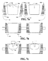
- Figures 7a-g depicts a cross sectional view of figure 6 showing only two of the three rows of cavities. The number of rows may me be more or less than three as shown in figure 6 .
- Each of the cavities is further provided with ventilation openings 704 for providing an access for moisture/liquid out of the cavities to the surroundings. This will be discussed in more details later.
- Figure 7a shows where the wet moulded products (701a,b) made from the cellulose fibers are released as indicated by an arrow 701 from a cellulose fibers mould (not shown) into the cavities of the blow mould 602.
- the left side 602a and the right side 602b define one row of cavities as shown in figure 6 and are preferably a single piece, respectively. The same applies for the left and right side of the cavities 602c,d.
- These semi-lid like cavities are attached to a moving system 710 that may be operated by a control unit (not shown) that operates the cavities from being in an open position to a closing position (as shown in figure 6 ), and vice versa.
- the semi-lid like cavities may be attached to the moving system for enabling this back and for movement of the left and right side of the cavities for the three rows of cavities.
- the cavities when releasing the wet moulded products (701a,b) into the blow cavities 602 of the blow mould, the cavities may be in an open position as shown here.
- Figure 7b shows where subsequent to releasing the wet moulded products in the cavities the cavities are moved from the open position to a closing position as indicated by arrows 709.
- FIG. 7e depicts where the plurality of lid-like portions 704 of the flexible material is placed into the wet moulded products.
- each of the lid-like portions 704 is associated with nozzles 706 that are connected to a pressure mechanism 705 (not shown).
- Figure 7d depicts where pressure is supplied by the pressure mechanism through the nozzles causing a simultaneous inflation of the deformable material into the shape of the plurality of cavities thereby pressing the wet moulded products into the shape of the cavities as indicated by arrows 708.
- the blow mould is pre-heated to an operation temperature, e.g. between 180-220°C.
- an operation temperature e.g. between 180-220°C.
- supplying a pressure of e.g. 40-60bar on the deformable material into the shape of the cavities of the blow mould, while the moulded products are in wet state the thermal contact between the moulded products in wet state and the cavities is increased.
- This increases the energy transfer from the cavities into the moulded product in wet state, which surprisingly leads to an almost instant evaporation of the moisture from the moulded product through the ventilation openings 704 of the cavities of the blow mould, turning them into a shell like structure defining the shape of the lids as shown in figure 7e .
- Figure 7f shows where the blow mould are moved from the closing position to the opening position for releasing the lids out of the cavities.
- the blow mould may first (not shown here) be rotated 180° to facilitate the releasing of the lids out of the blow mould
- the blow mould may be cooled down before releasing the resulting lids out of the cavities of the blow mould.
- Figure 7g shows the resulting lids, but tens, hundreds or thousands of such 100% environmentally friendly lids may be produced that are fully recyclable.
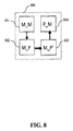
- FIG 8 shows an apparatus 800 according to the present invention for producing lids for containers from cellulose fibers, comprising a moulding mechanism (M_M) 801 for providing plurality of wet moulded products of a pre-defined shape.
- the moulding mechanism may e.g. comprise a robotic arm attached/mounted to a cellulose fibers mould (not shown) discussed in relation to figure 2 .
- the apparatus 800 further comprises means for placing (M_P) 802, which may be the above mentioned robotic arm, the wet moulded products into plurality of cavities (see e.g. 602 in figure 6 ) of a blow mould (e.g. 601 in figure 6 ), where the blow mould is pre-heated to an operating temperature as e.g.
- each of the plurality of cavities of the blow mould comprising plurality of ventilation openings.
- the apparatus further comprises means for placing (M_P') 803 a deformable material adjacent to the plurality of cavities of the blow mould, but this may e.g. be done by the above mentioned robotic arm, and a pressure mechanism (P_M) 804 for supplying a pressure on the deformable material at the plurality of cavities of the blow mould.
- the pressure causes a simultaneous inflation of the deformable material into the shape of the plurality of cavities thereby pressing the wet moulded product into the shape of the cavities, the plurality of ventilation openings acting as an exit for the moisture in the wet moulded products out of the cavities.
- the pressure means may as an example be the one discussed in relation to figure 7 .
Landscapes
- Engineering & Computer Science (AREA)
- Manufacturing & Machinery (AREA)
- Blow-Moulding Or Thermoforming Of Plastics Or The Like (AREA)
Abstract
This invention relates a method of producing lids (300) for containers from cellulose fibers. Plurality of wet moulded products made from the cellulose fibers are provided. A blow mould (601) pre-heated to an operating temperature is provided, the blow mould having plurality of cavities (602) defining the shape of the lids, each of the plurality of cavities having plurality of ventilation openings (704). The wet moulded products are placed into the plurality of cavities of the blow mould, a deformable material is placed adjacent to the plurality of cavities of the blow mould, and a pressure is supplied on the deformable material at the plurality of cavities of the blow mould, the supplied pressure causing a simultaneous inflation of the deformable material into the shape of the plurality of cavities thereby pressing the wet moulded products into the shape of the cavities, the plurality of ventilation openings acting as an exit for the moisture in the wet moulded products out of the cavities.
Description
- The present invention relates to a method and an apparatus for producing lids from cellulose fibers for containers.
- Lids for containers are well-known in the beverage container industry, e.g. most coffee shops in the world offer a take away service where a customer receives his coffee in a container, e.g. a paper cup, with a lid on top of the cup for sealing the opening of the container. Various designs of lids exist, e.g. lids with movable closing flap as disclosed in
US. Pat. No. 4,579,245 or a lid having a movable cover for the opening as disclosed inU.S. Pat. No. 4,790.444 . - Most of the lids used today are single-use lids and are typically made of plastic material, where after use the lids are typically end up as a waste material.
- The inventor of the present invention has appreciated that there is thus a need for lids that are fully recyclable and a way of producing such recyclable lids and has in consequence devised the present invention.
- It would be advantageous to be able to produce lids for containers that provide excellent sealing between the lids and the containers and that at the same time are fully recyclable and that may be produced at a mass production level.
- Moreover, it would be an advantageous to be able to produce such lids that have similar or the same appearance as prior art lids that are typically made of plastic material.
- In general, the invention preferably seeks to mitigate, alleviate or eliminate one or more of the above mentioned disadvantages singly or in any combination. In particular, it may be seen as an object of the present invention to provide a method of producing lids that solves the above mentioned problems, or other problems, of the prior art.
- To better address one or more of these concerns, in a first aspect of the invention a method is provided of producing lids for containers from cellulose fibers, comprising:
- providing plurality of wet moulded products made from the cellulose fibers,
- providing a blow mould pre-heated to an operating temperature, the blow mould comprising plurality of cavities defining the shape of the lids, each of the plurality of cavities comprising plurality of ventilation openings,
- placing the wet moulded products into the plurality of cavities of the blow mould,
- placing a deformable material adjacent to the plurality of cavities of the blow mould, and
- supplying a pressure on the deformable material at the plurality of cavities of the blow mould, the supplied pressure causing a simultaneous inflation of the deformable material into the shape of the plurality of cavities thereby pressing the wet moulded products into the shape of the cavities, the plurality of ventilation openings acting as an exit for the moisture in the wet moulded products out of the cavities.
- Supplying pressure on the deformable material into the shape of the cavities of the blow mould, while the moulded products are in wet state, increases the thermal contact between the moulded products in wet state and the cavities. This increases the energy transfer from the cavities into the moulded product in wet state, which surprisingly leads to an almost instant evaporation of the moisture from the moulded product through the ventilation openings of the cavities of the blow mould, turning them into a shell like structure defining the shape of the lids.
- Due to the flexibility of the deformable film and the high kinetic energy that will be produced in the deformable film due to the supplied pressure vie e.g. air or hydraulic pressure, the deformable material will impact on the inner side of the cavities of the blow mould with such a pressure that the deformable material will press the wet moulded products at all the surface and surface spots/areas on the inner side of the cavities, such as all types of protrusions, boundaries etc. Thus, all kinds of shapes on the outside of the lids may be done produced, e.g. any types of outwardly protruding parts such as mounting portions on the side wall of the lids that connect the lid to the containers in a manner that seals the lid on the container can be produced almost instantly.
- The deformable material may be at a room temperature during this, i.e. there may be no need to heat it up to a higher temperature during the production of the disposable containers. The deformable material may also be pre-heated to a given operating temperature during this process.
- Moreover, a single drying and shaping step is provided to produce the lids at a mass production level within few seconds time.
- The deformable material may be made of any type of material that preferably has high elasticity such as, but not limited to, latex, rubber, or any type of deformable plastic material having sufficient elasticity. The thickness of the deformable material may also be adapted to the type of products being produced, and may e.g. vary from being a millimeter or even less thick up to few millimeters thick.
- The term ventilation openings may be understood as any type access channels, access slits, or drainage channels for the moisture and/or the liquid in the wet moulded products, that may have any type of cross sectional shape, e.g. cylindrical, rectangular, elliptical etc. that interconnect the inside and the outside of the blow mould. As an example, the diameter of these ventilation holes/ventilation openings may have a dimension ranging from 1mm to micrometer range such as 50µm.
- In one embodiment, the cellulose fibers is a plant based cellulose. In one embodiment, the plant based cellulose is bagasse produced from sugarcane. Bagasse is 100% biodegradable and compostable and a bi product of sugar cane fiber which is left after the juice has been extracted from the sugar cane, but hundred thousands of tons of bagasse remains to be used yearly.
- Also, due to new processing methods bagasse has become a very cheap product and thus the value of bagasse may be increased significantly and therefore a favorable option is provided for producing lids for containers using bagasse.
- Further, bagasse is annually renewable as opposed to trees that take 7 top 20 years to grow and is biodegradable as trees.
- More importantly, a 100% environmentally friendly product is produced that fully recyclable. Also, due to the property of bagasse, the lids will have at least the same strength as the lids being used today and similar if not the same appearance as lids that are e.g. made of plastic material.
- In one embodiment, the wet moulded products have a geometry essentially following the geometry of the interior of the plurality of cavities of the blow mould. The risk that the wet moulded product comes apart during production is reduced because the wet moulded products can be sensitive. Therefore, the better they fit into the cavities the more reliable will the production be.
- In one embodiment, the deformable material comprises plurality of lid like portions, the step of placing the deformable material adjacent to the plurality of cavities of the blow mould includes placing the plurality of lid like portions of the deformable material at least partly into the plurality of cavities, where supplying the pressure on the deformable material into the shape of the plurality of cavities comprises supplying a pressure on the plurality of the lid like portions of the deformable material causing a simultaneous inflation of the lid like portions of the deformable material into the plurality of cavities of the blow mould. Accordingly, tens or hundreds of ldis may be produced within few seconds time. The lid like portions may in one embodiment have a geometrical shape essentially following the geometry of the interior of the plurality of cavities of the blow mould.
- In one embodiment, each of the plurality of cavities comprise two or more portions, where while the lids are produced each of the two or more portions are in a closed position, where subsequent to the inflation of the deformable material into the shape of the plurality of cavities each of the two or more portions of the cavities are moved from the closed position to an opening position so as to facilitate the releasing of the produced lids from the cavities. As an example, each of the cavities may be divided into two parts, preferably two identical parts. By dividing the cavities into such two or more portions it is possible to produce lids that have outwardly protruding side potions, e.g. a mounting portions at the side of the lids that extends out from the sides of the lids, where the mounting portions may depend from a lower edges of the side walls of the lids and are adapted for connecting the lids to the containers in a manner that seals the lids on the containers.
- In one embodiment, when supplying a pressure on the deformable material into the shape of the cavities of the blow mould the operating temperature of the blow mould is in the range of 150-250°C, preferably in the range of 180-220°C.
- In one embodiment, the pressure supplied on the deformable material is in the range of 20-80bar, preferably between 30-70bar, more preferably between 40-60bar, most preferably around 50bar.
- In one embodiment, the method further comprises depositing a film on an inner surface of the produced lids, where the film comprises an aluminium oxide film, a silicon oxynitride film or a silicon oxide film. Such films, e.g. a silicon oxide film, provide a kind of a "nano-glass" films, which provides an environmentally favorable barrier needed for e.g. all types of paper cups such as coffee/tea paper cups between the beverages and the outer shell structure.
- Thus, the commonly used Polyethelene films that are glued onto the inside of product shells to provide such a barrier are no longer needed, but such Polyethylene films are very difficult to recycle. Thus, utilizing this type of a coating on the inner side of the product shells (e.g. paper cup shell) ensures that the disposable product is fully sustainable and low cost to entry.
- In one embodiment, the wet moulded products of the pre-defined shape is provided by means of:
- dipping a cellulose fiber mould having a permeable moulding surface side into the cellulose fibers,
- applying a vacuum to the cellulose fiber mould to draw cellulose fibers through the permeable surface side leaving an outwardly or inwardly facing fiber mat on the permeable moulding surface side, and
- removing the cellulose fiber mould from the cellulose fibers and subsequently removing the resulting moulded product of the lid-like shape from the cellulose fiber mould.
- The resulting moulded product of the pre-defined shape of the cellulose fiber mould may subsequently be placed directly into the plurality of cavities of the blow mould. The shape of the cellulose fiber mould is preferably substantially the same as the shape of the cavities of 6 the blow mould, such that the moulded products in wet form fit directly into the cavities of the blow mould. This means that the cellulose fiber mould also has a plurality of cellulose fiber mould cavities having substantially the same geometrical shape as the cavities of the blow mould It is thus possible to move the cellulose fiber mould, subsequent to removing the cellulose fiber mould from the cellulose fibers, towards and adjacent to the blow mould and release the moulded products in wet form directly into the cavities of the blow mould.
- In a second aspect of the invention lid for a container is provided adapted for holding a flowable substance, comprising:
- a cover adapted to span an opening of an upper portion of the container defined by an upper rim of the container,
- a top wall,
- a side wall depending from the a peripheral edge of the top wall,
- a mounting portion depending from a lower edge of the side wall, the mounting portion being adapted for connecting the lid to the container in a manner that seals the lid on the container,
- Accordingly, an environmentally friendly lid is provided that is fully recyclable and that is produced from e.g. bagasse that is 100% biodegradable and compostable and a bi product of sugar cane fiber.
- In a third aspect of the invention an apparatus is provided for producing lids for containers from cellulose fibers, comprising:
- a moulding mechanism (M_M) for providing plurality of wet moulded products (801a,b) made from the cellulose fibers,
- means for placing (M_P) the wet moulded products into plurality of cavities of a blow mould, each of the plurality of cavities defining the shape of the lids, the blow mould being pre-heated to an operating temperature, each of the plurality of cavities of the blow mould comprising plurality of ventilation openings,
- means for placing (M_P') a deformable material adjacent to the plurality of cavities of the blow mould,
- a pressure mechanism (P_M) for supplying a pressure on the deformable material at the plurality of cavities of the blow mould, the supplied pressure causing a simultaneous inflation of the deformable material into the shape of the plurality of cavities thereby pressing the wet moulded products into the shape of the cavities, the plurality of ventilation openings acting as an exit for the moisture in the wet moulded products out of the cavities.
- The pressure mechanism comprises in one embodiment at least one nozzle or nozzle like part such as at least one thin steel rod or the like that is connected to high pressure gas source such as high pressurized air.
- The at least one nozzle like part may be associated to a moving mechanism that places the nozzle like part automatically inside or above the deformable material distantly away from the blow mould. The pressure mechanism and the flexible material may also be internally fixed in relation the each other within a housing, where the deformable material defines of side of the housing and another side of the housing may be a fixed material such as a steel plate, and where the pressure source may be comprised there between.
- The at least one nozzle like part may be operated such that it blows e.g. highly pressurized gas into or onto the deformable material resulting in the simultaneous expansion of the wet moulded product into the shape of the blow mould.
- In case the deformable material has a pre-defined shape essential following the shape of the plurality of cavities of the blow mould, one or more nozzles may be associated to each of the pre-defined shapes of the deformable material, such that plurality of localized pressures are supplied. If e.g. the deformable material has a plurality of lid like portions, the one or more nozzles are associated to each of these lid like portions.
- In another embodiment, the pressure source comprises a hydraulic pressure source where any type of liquid may be used as a pressure source for supplying a pressure on the deformable material into the shape of the blow mould.
- In one embodiment, each of the plurality of cavities comprise two or more portions, where each of the two or more portions are moveable by a moving system from a closing position where the lids are produced to an open position, where the moving system is operated in a way such that subsequent to the inflation of the deformable material into the shape of the plurality of cavities each of the two or more portions of the cavities are moved from the closed position to an opening position so as to facilitate the releasing of the produced lids from the cavities.
- In one embodiment, the blow mould comprises plurality of rows of blow moulds forming a matrix of cavities, and where each of the rows of cavities is defined by two identical semi-lid like cavity mould rows arranged opposite to each other, where each of the cavity mould rows are attached to a moving mechanism that is adapted to move them from a closed position to an open position, and vice verse, from an open position to a closing position. Thus a simple solution is provide for releasing multiple of ready lids simultaneously, but semi-lid like cavity mould rows may contain tens or hundreds of lids, instead of e.g. operating the each individual cavity separately.
- In general the various aspects of the invention may be combined and coupled in any way possible within the scope of the invention. These and other aspects, features and/or advantages of the invention will be apparent from and elucidated with reference to the embodiments described hereinafter.
- Embodiments of the invention will be described, by way of example only, with reference to the drawings, in which
-
Figure 1 shows a flow diagram of a method according to the present invention of producing lids for containers from cellulose fibers, -
Figure 2 shows a flowchart of one embodiment of providing the wet moulded product, -
Figures 3 and 4 depict a side view and a perspective view of an example of a lid for a container that is produced by the method according to the present invention, -
Figure 5 depicts where the 300 shown infigure 3 and 4 has been connected to the container, -
Figure 6 depicts graphically one embodiment of the present invention of producing lids from cellulose fibers, -
Figures 7a-g depicts a cross sectional view offigure 6 , and -
Figure 8 shows an apparatus according to the present invention for producing disposable products from cellulose fibers. -
Figure 1 shows a flow diagram of a method according to the present invention of producing lids for containers from cellulose fibers. The cellulose fibers cellulose fibers may plant based cellulose, where the plant based cellulose may in one embodiment be bagasse produced from sugarcane. - In a first step (S1) 101, wet moulded products made from the cellulose fibers is provided. It is not an essence of the present invention how the wet moulded products are provided, but as will be discussed in more details in relation to
figures 2 , this may be done using vacuum forming techniques well known in the art, e.g. similar to those used for the formation of e.g. egg boxes. - In a second step (S2) 103, the wet moulded products are placed into plurality of cavities of a blow mould, where the cavities define the shape of the lids to be produced and further have plurality of ventilation openings. The blow mould is pro-heated to an operating temperature, which in one embodiment may be in the range of 150-250°C, preferably in the range of 180-220°C.
- This step of placing the wet moulded products into the plurality of cavities of the blow mould may in one embodiment be a fully manual or semi manual process where on operator places the moulded products in wet state into the mould, or this may be a fully automatic process where e.g. a robotic arm and the like puts the moulded products in wet state it into the cavities of the blow mould. The ventilation openings may have all kinds of geometry, having a hole like structure, slits, etc.
- In one embodiment, the wet moulded products have a geometrical shape essentially following the geometrical shape of the cavities of the blow mould, e.g. such that the wet moulded products may have a lid-like shape.
- In a third step (S3) 105, a deformable material is placed adjacent to or into the cavities of the blow mould containing the wet moulded products. The deformable material may be a substantially flat film material or, as will be discussed in more details later, comprise plurality of portions each of which having e.g. a pocket like shape portions or a shape that e.g. substantially matches the shape of the cavities of the blow mould, e.g. have a lid-like shape. The deformable material implemented may be any type of material having preferably high elasticity, e.g. a solid material that returns to its original shape and size after the forces deforming them, i.e. in this case the pressure, have been removed. An example of such material is Latex, and any type of plastic materials, rubber and the like.
- In a fourth step (S4) 107, a pressure is supplied on the deformable material at the plurality of cavities. This supplied pressure causes an inflation of the deformable material into the shape of the cavities while simultaneously pressing the wet moulded products into the shape of the cavities. The plurality of ventilation openings act as an exit for the moisture in the wet moulded products out of the cavities. The supplied pressure may in one embodiment be in the range of 20-80bar, preferably between 30-70bar, more preferably between 40-60bar, most preferably around 50bar.
- This simultaneous formation of the wet moulded products into the shape of the cavities of the blow mould cause an almost instant drying of the moulded products into a shell like structure having the shape of the lids.
- Supplying such a high pressure on the deformable material will ensure that the deformable material, and thus the wet moulded products, will reach into every corner, niche and intrusions of the blow mould. This allows shaping the wet moulded product precisely into the shape of the cavities of the mould such that the resulting shell structure has a nice and smooth shape looking similar or identical to a texture of e.g. plastic lids that are commonly used today. The intrusions may as an example be a logo and/or any type of registered trademark text symbols.
- More importantly, this drying process takes only around second (or even less), which is only a fraction of the time needed to produce a shell-like product from a wet moulded with prior art methods.
- In one embodiment, the method according to the present invention may further comprise a further optional step (S5) 109 of depositing a film on an inner surface of the moulded products, where the film may comprise an aluminium oxide film, or a silicon oxynitride film or a silicon oxide film. Such a film acts as a "nano-glass" film, which provides an environmentally favorable barrier and/or isolation.
-
Figure 2 shows a flowchart of one embodiment of providing the wet moulded products discussed in relation tofigure 1 . - In a first step (S1') 301, a cellulose fibers mould having a permeable moulding surface side is dipped into cellulose fibers, preferably plant based cellulose which is preferably bagasse produced from sugarcane.
- In a second step (S2') 303, a vacuum is applied to the inner side of the cellulose fibers mould to draw cellulose fibers through the permeable surface side leaving an outwardly or inwardly facing fiber mat on the permeable moulding surface side.
- In a third step (S3') 305, the cellulose fibers mould is removed from the cellulose fibers and subsequently the resulting wet moulded products are removed from the cellulose fibers mould. This may e.g. be done by removing and placing the wet moulded products directly into the cavities of the blow mould as discussed in relation to
figure 1 . As an example, the cellulose fibers mould may be carried by a robotic arm that may e.g. place the cellulose fibers mould adjacent to the blow mould while keeping an under pressure of the blow mould preventing that the wet moulded products fall out of the cellulose fibers mould. By positioning the cellulose fibers mould directly above the blow mould, the pressure of the cellulose fibers mould may be released causing the wet moulded products to fall directly into the cavities. -
Figures 3 and 4 depict a side view (figure 3 ) and a perspective view (figure 4 ) of an example of a lid for a container that is produced by the method according to the present invention, where the lid comprises acover 301, atop wall 306, aside wall 302, a mountingportion 304 and a generallyannual skirt 305, where the top wall, the side wall, the mounting portion and the annual skirt are a single integral part. - The
cover 301 is adapted to span an openings of an upper portion of the container defined by an upper rim of the container having theside wall 302 depending from the a peripheral edge of thetop wall 306, where the mountingportion 304 is depending from alower edge 303 of theside wall 302. The mountingportion 304 is adapted for connecting thelid 300 to the container in a manner that seals thelid 300 on the container so as to prevent leakage of the container content between thelid 300 and the when the lid is positioned on the container. Theannual skirt 305 is adapted to facilitate positioning thelid 300 on the container and to remove thelid 300 from the container. -
Figure 5 depicts where thelid 300 shown infigure 3 and 4 has been connected to thecontainer 501, which may e.g. be a container for a hot beverage such as coffee, tee etc. -
Figure 6 depicts graphically one embodiment of the present invention of producing lids from cellulose fibers. - A
female blow mould 601 is provided comprising plurality of lid-like cavities 602. The female blow mould is typically, during use, preheated to an operating temperature such as, but not limited to, 180-220°C, where the plurality of lid-like cavities 602 have ventilation openings (not shown here). - As discussed in relation to
figures 1 and 2 , moulded products in wet state are provided where the moulded products preferably have a lid-like shape or a shape that essentially follows the shape of thecavities 602. This may be done manually, semi manually or fully automatically as discussed previously, where e.g. the moulded products in wet state may be released from a cellulose fibers mould (not shown) directly into thecavities 602 of theblow mould 601. - A
deformable material 603 is provided comprising plurality of lid-like portions 604 having a shape similar to the shape of the cup like or pocket likecavities 602. Shown is also anupper coverage 605, but thedeformable material 603 and this upper coverage may me a single unit. As will be discussed later, plurality of pressure means such as plurality of nozzles may be provided within an interior between thedeformable material 603 and thisupper coverage 605. - The movement of the
deformable material 604 having the lid-like portions 604 and the upper coverage may be operated by a robotic arm or system. - As will be discussed in more details in relation to
figure 7 and is not shown here, each of the plurality of cavities may comprise two or more portions, preferably two identical portions, which when put together form the cavities defining the shape of the lids. As an example, each of the three rows of cavities shown here may be formed by two moulds of three semi-lid mould like cavities arranged opposite to each other, where each of these are attached to a moving mechanism that is adapted to move the each of the three rows of cavities (the number of raws can of course be more or less than three) together to a closing position as shown here, or to an open position as will be discussed in more details later in relation tofigure 7 . -
Figures 7a-g depicts a cross sectional view offigure 6 showing only two of the three rows of cavities. The number of rows may me be more or less than three as shown infigure 6 . - Each of the cavities is further provided with
ventilation openings 704 for providing an access for moisture/liquid out of the cavities to the surroundings. This will be discussed in more details later. -
Figure 7a shows where the wet moulded products (701a,b) made from the cellulose fibers are released as indicated by an arrow 701 from a cellulose fibers mould (not shown) into the cavities of theblow mould 602. Theleft side 602a and theright side 602b define one row of cavities as shown infigure 6 and are preferably a single piece, respectively. The same applies for the left and right side of thecavities 602c,d. - These semi-lid like cavities are attached to a moving
system 710 that may be operated by a control unit (not shown) that operates the cavities from being in an open position to a closing position (as shown infigure 6 ), and vice versa. As shown here, the semi-lid like cavities may be attached to the moving system for enabling this back and for movement of the left and right side of the cavities for the three rows of cavities. - As shown in
figure 7a , when releasing the wet moulded products (701a,b) into theblow cavities 602 of the blow mould, the cavities may be in an open position as shown here. -
Figure 7b shows where subsequent to releasing the wet moulded products in the cavities the cavities are moved from the open position to a closing position as indicated byarrows 709. -
Figure 7e depicts where the plurality of lid-like portions 704 of the flexible material is placed into the wet moulded products. In this embodiment, each of the lid-like portions 704 is associated withnozzles 706 that are connected to a pressure mechanism 705 (not shown). -
Figure 7d depicts where pressure is supplied by the pressure mechanism through the nozzles causing a simultaneous inflation of the deformable material into the shape of the plurality of cavities thereby pressing the wet moulded products into the shape of the cavities as indicated byarrows 708. - As already discussed in relation to
figure 1 , the blow mould is pre-heated to an operation temperature, e.g. between 180-220°C. Thus, supplying a pressure of e.g. 40-60bar on the deformable material into the shape of the cavities of the blow mould, while the moulded products are in wet state the thermal contact between the moulded products in wet state and the cavities is increased. This increases the energy transfer from the cavities into the moulded product in wet state, which surprisingly leads to an almost instant evaporation of the moisture from the moulded product through theventilation openings 704 of the cavities of the blow mould, turning them into a shell like structure defining the shape of the lids as shown infigure 7e . -
Figure 7f shows where the blow mould are moved from the closing position to the opening position for releasing the lids out of the cavities. The blow mould may first (not shown here) be rotated 180° to facilitate the releasing of the lids out of the blow mould - In one embodiment, the blow mould may be cooled down before releasing the resulting lids out of the cavities of the blow mould.
-
Figure 7g shows the resulting lids, but tens, hundreds or thousands of such 100% environmentally friendly lids may be produced that are fully recyclable. -
Figure 8 shows anapparatus 800 according to the present invention for producing lids for containers from cellulose fibers, comprising a moulding mechanism (M_M) 801 for providing plurality of wet moulded products of a pre-defined shape. The moulding mechanism may e.g. comprise a robotic arm attached/mounted to a cellulose fibers mould (not shown) discussed in relation tofigure 2 . Theapparatus 800 further comprises means for placing (M_P) 802, which may be the above mentioned robotic arm, the wet moulded products into plurality of cavities (see e.g. 602 infigure 6 ) of a blow mould (e.g. 601 infigure 6 ), where the blow mould is pre-heated to an operating temperature as e.g. discussed previously, each of the plurality of cavities of the blow mould comprising plurality of ventilation openings. The apparatus further comprises means for placing (M_P') 803 a deformable material adjacent to the plurality of cavities of the blow mould, but this may e.g. be done by the above mentioned robotic arm, and a pressure mechanism (P_M) 804 for supplying a pressure on the deformable material at the plurality of cavities of the blow mould. The pressure causes a simultaneous inflation of the deformable material into the shape of the plurality of cavities thereby pressing the wet moulded product into the shape of the cavities, the plurality of ventilation openings acting as an exit for the moisture in the wet moulded products out of the cavities. The pressure means may as an example be the one discussed in relation tofigure 7 . - While the invention has been illustrated and described in detail in the drawings and foregoing description, such illustration and description are to be considered illustrative or exemplary and not restrictive; the invention is not limited to the disclosed embodiments. Other variations to the disclosed embodiments can be understood and effected by those skilled in the art in practicing the claimed invention, from a study of the drawings, the disclosure, and the appended claims. In the claims, the word "comprising" does not exclude other elements or steps, and the indefinite article "a" or "an" does not exclude a plurality. The mere fact that certain measures are recited in mutually different dependent claims does not indicate that a combination of these measured cannot be used to advantage.
Claims (14)
- A method of producing lids (706s, 706b) for containers from cellulose fibers, comprising:• providing (101) plurality of wet moulded products (701s,b) made from the cellulose fibers,• providing a blow mould (601) pre-heated to an operating temperature, the blow mould comprising plurality of cavities (602) defining the shape of the lids, each of the plurality of cavities comprising plurality of ventilation openings,• placing (103) the wet moulded products into the plurality of cavities of the blow mould,• placing (105) a deformable material (604) adjacent to the plurality of cavities of the blow mould, and• supplying (107) a pressure on the deformable material at the plurality of cavities of the blow mould, the supplied pressure causing a simultaneous inflation of the deformable material into the shape of the plurality of cavities thereby pressing the wet moulded products into the shape of the cavities, the plurality of ventilation openings acting as an exit for the moisture in the wet moulded products out of the cavities.
- The method according to claim 1, wherein the cellulose fibers is a plant based cellulose.
- The method according to claim 2, wherein the plant based cellulose is bagasse produced from sugarcane.
- The method according to any of the preceding claims, wherein the wet moulded products have a geometry essentially following the geometry of the interior of the plurality of cavities of the blow mould.
- The method according to any of the preceding claims, wherein the deformable material comprises plurality of lid like portions, the step of placing the deformable material (403) adjacent to the plurality of cavities of the blow mould includes placing the plurality of lid like portions of the deformable material at least partly into the plurality of cavities, where supplying the pressure on the deformable material into the shape of the plurality of cavities comprises supplying a pressure on the plurality of the lid like portions of the deformable material causing a simultaneous inflation of the lid like portions of the deformable material into the plurality of cavities of the blow mould.
- The method according to any of the preceding claims, wherein each of the plurality of cavities comprise two or more portions (602a,b, 601c,d), where while the lids are produced each of the two or more portions are in a closed position, where subsequent to the inflation of the deformable material into the shape of the plurality of cavities each of the two or more portions of the cavities are moved from the closed position to an opening position so as to facilitate the releasing of the produced lids from the cavities.
- The method according to any of the preceding claims, wherein when supplying a pressure on the deformable material into the shape of the cavities of the blow mould the operating temperature of the blow mould is in the range of 150-250°C, preferably in the range of 180-220°C.
- The method according to any of the preceding claims, wherein the pressure supplied on the deformable material is in the range of 20-80bar, preferably between 30-70bar, more preferably between 40-60bar, most preferably around 50bar.
- The method according to any of the preceding claims, further comprising depositing a film (109) on an inner surface of the produced lids, where the film comprises an aluminium oxide film, a silicon oxynitride film or a silicon oxide film.
- The method according to any of the preceding claims, wherein the wet moulded products of the pre-defined shape is provided by means of:• dipping a cellulose fiber mould having a permeable moulding surface side into the cellulose fibers (201),• applying a vacuum to the cellulose fiber mould to draw cellulose fibers through the permeable surface side leaving an outwardly or inwardly facing fiber mat on the permeable moulding surface side (203), and• removing the cellulose fiber mould from the cellulose fibers and subsequently removing the resulting moulded product of the lid-like shape from the cellulose fiber mould (205).
- A lid (300) for a container (501) adapted for holding a flowable substance, comprising:• a cover (301) adapted to span an opening of an upper portion of the container defined by an upper rim of the container,• a top wall (306),• a side wall (302) depending from the a peripheral edge of the top wall (306),• a mounting portion (304) depending from a lower edge (303) of the side wall (302), the mounting portion being adapted for connecting the lid (300) to the container (501) in a manner that seals the lid (300) on the container (501),wherein the lid (300) is produced by the method according to any of the claims 1-11.
- An apparatus (800) for producing lids for containers from cellulose fibers, comprising:• a moulding mechanism (M_M) (801) for providing plurality of wet moulded products made from the cellulose fibers,• means for placing (M_P) (802) the wet moulded products into plurality of cavities of a blow mould (601), each of the plurality of cavities (602) defining the shape of the lids, the blow mould being pre-heated to an operating temperature, each of the plurality of cavities of the blow mould comprising plurality of ventilation openings,• means for placing (M_P') (803) a deformable material (604) adjacent to the plurality of cavities of the blow mould,• a pressure mechanism (P_M) (804) for supplying a pressure on the deformable material at the plurality of cavities of the blow mould, the supplied pressure causing a simultaneous inflation of the deformable material into the shape of the plurality of cavities thereby pressing the wet moulded products into the shape of the cavities, the plurality of ventilation openings acting as an exit for the moisture in the wet moulded products out of the cavities.
- The apparatus according to claim 12, wherein each of the plurality of cavities comprise two or more portions (602a,b), where each of the two or more portions are moveable by a moving system from a closing position where the lids are produced to an open position,
where the moving system is operated in a way such that subsequent to the inflation of the deformable material into the shape of the plurality of cavities each of the two or more portions of the cavities are moved from the closed position to an opening position so as to facilitate the releasing of the produced lids from the cavities. - The apparatus according to claim 12 or 13, wherein the blow mould comprises plurality of rows of blow moulds forming a matrix of cavities, and where each of the rows of cavities is defined by two identical semi-lid like cavity mould rows arranged opposite to each other, where each of the cavity mould rows are attached to a moving mechanism that is adapted to move them from a closed position to an open position, and vice verse, from an open position to a closing position.
Priority Applications (1)
| Application Number | Priority Date | Filing Date | Title |
|---|---|---|---|
| EP15001100.5A EP3081693A1 (en) | 2015-04-16 | 2015-04-16 | A method of producing lids from cellulose fibers for containers |
Applications Claiming Priority (1)
| Application Number | Priority Date | Filing Date | Title |
|---|---|---|---|
| EP15001100.5A EP3081693A1 (en) | 2015-04-16 | 2015-04-16 | A method of producing lids from cellulose fibers for containers |
Publications (1)
| Publication Number | Publication Date |
|---|---|
| EP3081693A1 true EP3081693A1 (en) | 2016-10-19 |
Family
ID=52991418
Family Applications (1)
| Application Number | Title | Priority Date | Filing Date |
|---|---|---|---|
| EP15001100.5A Withdrawn EP3081693A1 (en) | 2015-04-16 | 2015-04-16 | A method of producing lids from cellulose fibers for containers |
Country Status (1)
| Country | Link |
|---|---|
| EP (1) | EP3081693A1 (en) |
Cited By (4)
| Publication number | Priority date | Publication date | Assignee | Title |
|---|---|---|---|---|
| CN108425292A (en) * | 2018-04-24 | 2018-08-21 | 吴刚 | A kind of preparation method of buffer-type moulded paper pulp product |
| JP2022127184A (en) * | 2021-02-19 | 2022-08-31 | 王子ホールディングス株式会社 | lid |
| WO2024132232A1 (en) * | 2022-12-20 | 2024-06-27 | Krones Ag | Method and device for producing a fiber-containing container, radially elastic fiber-containing continuous tube, and fiber-containing container |
| WO2025040608A1 (en) * | 2023-08-21 | 2025-02-27 | Societe Des Produits Nestle S.A. | Moulded pulp article |
Citations (5)
| Publication number | Priority date | Publication date | Assignee | Title |
|---|---|---|---|---|
| US4579245A (en) | 1985-06-10 | 1986-04-01 | Narushko Suzanne B | Disposable leakproof container lids |
| US4790444A (en) | 1986-11-27 | 1988-12-13 | Terzi Stampi S.n.c.di Dario Terzi & C. | Cup-cap combination for soft drink cans |
| WO2010124300A1 (en) * | 2009-04-24 | 2010-10-28 | Seanet Development, Inc. | Processes for molding pulp paper containers and lids |
| WO2013192260A1 (en) * | 2012-06-19 | 2013-12-27 | Pepsico, Inc. | Method for making molded fiber bottles |
| WO2015056276A1 (en) * | 2013-10-18 | 2015-04-23 | Emery Silfurtun Inc. | A method and an apparatus for producing disposable products from cellulose fibers |
-
2015
- 2015-04-16 EP EP15001100.5A patent/EP3081693A1/en not_active Withdrawn
Patent Citations (5)
| Publication number | Priority date | Publication date | Assignee | Title |
|---|---|---|---|---|
| US4579245A (en) | 1985-06-10 | 1986-04-01 | Narushko Suzanne B | Disposable leakproof container lids |
| US4790444A (en) | 1986-11-27 | 1988-12-13 | Terzi Stampi S.n.c.di Dario Terzi & C. | Cup-cap combination for soft drink cans |
| WO2010124300A1 (en) * | 2009-04-24 | 2010-10-28 | Seanet Development, Inc. | Processes for molding pulp paper containers and lids |
| WO2013192260A1 (en) * | 2012-06-19 | 2013-12-27 | Pepsico, Inc. | Method for making molded fiber bottles |
| WO2015056276A1 (en) * | 2013-10-18 | 2015-04-23 | Emery Silfurtun Inc. | A method and an apparatus for producing disposable products from cellulose fibers |
Cited By (4)
| Publication number | Priority date | Publication date | Assignee | Title |
|---|---|---|---|---|
| CN108425292A (en) * | 2018-04-24 | 2018-08-21 | 吴刚 | A kind of preparation method of buffer-type moulded paper pulp product |
| JP2022127184A (en) * | 2021-02-19 | 2022-08-31 | 王子ホールディングス株式会社 | lid |
| WO2024132232A1 (en) * | 2022-12-20 | 2024-06-27 | Krones Ag | Method and device for producing a fiber-containing container, radially elastic fiber-containing continuous tube, and fiber-containing container |
| WO2025040608A1 (en) * | 2023-08-21 | 2025-02-27 | Societe Des Produits Nestle S.A. | Moulded pulp article |
Similar Documents
| Publication | Publication Date | Title |
|---|---|---|
| EP3081693A1 (en) | A method of producing lids from cellulose fibers for containers | |
| CN113272495B (en) | Pick-up pressing device and method for producing 3D molded products from pulp slurry | |
| KR102139305B1 (en) | Method of manufacturing an article having a smoothed periphery | |
| FI56787C (en) | ANORDING FOER ATT FOERBINDA EN FOLIE MED ETT GENOM FORMSPRUTNING FRAMSTAELLT FOEREMAOL | |
| BR112019004861B1 (en) | PROCESS FOR MANUFACTURING A DISTRIBUTION CAPSULE AND APPARATUS FOR HIGH-SPEED CONTINUOUS THERMOFORMING OF PULP MATERIALS FOR PULP-BASED PRODUCTS | |
| US11466410B2 (en) | Lid, method of producing lid, and molds for forming molded pulp | |
| NO800588L (en) | PROCEDURE FOR CLOSING CARTON FAITH AND APPROACH FOR IMPLEMENTATION OF THE PROCEDURE | |
| NO140056B (en) | ANALOGICAL PROCEDURE FOR THE PREPARATION OF THERAPEUTIC ACTIVE OLEPHINIC 4-SUBSTITUTED PIPERIDINO DERIVATIVES | |
| CA2063086A1 (en) | Opening device for a packaging container and method of manufacturing the same | |
| EP2576184B1 (en) | Plate and apparatus for forming a plastic material flanged hollow article | |
| CN106687272A (en) | Molding apparatus and method for manufacturing an opening device | |
| EP2808152A1 (en) | A method and a system of producing disposable container from pulp slurry containing a fiber | |
| JPS6012234B2 (en) | Molded pulp product with plastic liner and method for manufacturing the same | |
| EP2933377A1 (en) | A method and an apparatus for producing disposable products from cellulose fibers | |
| WO2008035082A1 (en) | Method and apparatus for manufacturing a food packaging container | |
| WO2015056276A1 (en) | A method and an apparatus for producing disposable products from cellulose fibers | |
| ITTO20110043A1 (en) | PROCEDURE FOR PACKAGING A PRODUCT INTO A HERMETIC SHEET OF MATERIAL IN SHEET | |
| EP3725492B1 (en) | Container with a barrier film and method of manufacturing a container with a barrier film | |
| EP3885118A1 (en) | Method of manufacturing a container open at the top with a peripheral flange and a barrier film | |
| US20100075076A1 (en) | Spread structure of a multiple layers container | |
| EP1974898B1 (en) | Method for forming three-dimensional containers of extensible paper material. | |
| US20030122287A1 (en) | Method of manufacturing packaging articles, and a corresponding manufacturing machine | |
| HRP20241158T1 (en) | PROCEDURE AND TOOL FOR THE PRODUCTION OF CONTAINERS FROM THERMOPLASTIC MATERIAL AND CONTAINERS | |
| EP0546234A1 (en) | An arrangement in moulding tools intended for the injection moulding of a container while simultaneously affixing a label or the like thereto | |
| DE1704091A1 (en) | Process for the production of molded bodies, in particular containers, by thermoforming plastic into a mold |
Legal Events
| Date | Code | Title | Description |
|---|---|---|---|
| PUAI | Public reference made under article 153(3) epc to a published international application that has entered the european phase |
Free format text: ORIGINAL CODE: 0009012 |
|
| AK | Designated contracting states |
Kind code of ref document: A1 Designated state(s): AL AT BE BG CH CY CZ DE DK EE ES FI FR GB GR HR HU IE IS IT LI LT LU LV MC MK MT NL NO PL PT RO RS SE SI SK SM TR |
|
| AX | Request for extension of the european patent |
Extension state: BA ME |
|
| STAA | Information on the status of an ep patent application or granted ep patent |
Free format text: STATUS: THE APPLICATION IS DEEMED TO BE WITHDRAWN |
|
| 18D | Application deemed to be withdrawn |
Effective date: 20170420 |