EP3081480A2 - Electro-hydraulic servo valve control system - Google Patents
Electro-hydraulic servo valve control system Download PDFInfo
- Publication number
- EP3081480A2 EP3081480A2 EP16164384.6A EP16164384A EP3081480A2 EP 3081480 A2 EP3081480 A2 EP 3081480A2 EP 16164384 A EP16164384 A EP 16164384A EP 3081480 A2 EP3081480 A2 EP 3081480A2
- Authority
- EP
- European Patent Office
- Prior art keywords
- signal
- polar
- electro
- control system
- hydraulic servo
- Prior art date
- Legal status (The legal status is an assumption and is not a legal conclusion. Google has not performed a legal analysis and makes no representation as to the accuracy of the status listed.)
- Granted
Links
Images
Classifications
-
- G—PHYSICS
- G05—CONTROLLING; REGULATING
- G05D—SYSTEMS FOR CONTROLLING OR REGULATING NON-ELECTRIC VARIABLES
- G05D7/00—Control of flow
- G05D7/06—Control of flow characterised by the use of electric means
- G05D7/0617—Control of flow characterised by the use of electric means specially adapted for fluid materials
- G05D7/0629—Control of flow characterised by the use of electric means specially adapted for fluid materials characterised by the type of regulator means
- G05D7/0635—Control of flow characterised by the use of electric means specially adapted for fluid materials characterised by the type of regulator means by action on throttling means
-
- G—PHYSICS
- G05—CONTROLLING; REGULATING
- G05B—CONTROL OR REGULATING SYSTEMS IN GENERAL; FUNCTIONAL ELEMENTS OF SUCH SYSTEMS; MONITORING OR TESTING ARRANGEMENTS FOR SUCH SYSTEMS OR ELEMENTS
- G05B19/00—Program-control systems
- G05B19/43—Program-control systems fluidic
- G05B19/46—Program-control systems fluidic hydraulic
-
- B—PERFORMING OPERATIONS; TRANSPORTING
- B64—AIRCRAFT; AVIATION; COSMONAUTICS
- B64C—AEROPLANES; HELICOPTERS
- B64C13/00—Control systems or transmitting systems for actuating flying-control surfaces, lift-increasing flaps, air brakes, or spoilers
-
- B—PERFORMING OPERATIONS; TRANSPORTING
- B64—AIRCRAFT; AVIATION; COSMONAUTICS
- B64C—AEROPLANES; HELICOPTERS
- B64C13/00—Control systems or transmitting systems for actuating flying-control surfaces, lift-increasing flaps, air brakes, or spoilers
- B64C13/24—Transmitting means
- B64C13/38—Transmitting means with power amplification
- B64C13/40—Transmitting means with power amplification using fluid pressure
-
- B—PERFORMING OPERATIONS; TRANSPORTING
- B64—AIRCRAFT; AVIATION; COSMONAUTICS
- B64C—AEROPLANES; HELICOPTERS
- B64C13/00—Control systems or transmitting systems for actuating flying-control surfaces, lift-increasing flaps, air brakes, or spoilers
- B64C13/24—Transmitting means
- B64C13/38—Transmitting means with power amplification
- B64C13/50—Transmitting means with power amplification using electrical energy
- B64C13/503—Fly-by-Wire
-
- G—PHYSICS
- G05—CONTROLLING; REGULATING
- G05B—CONTROL OR REGULATING SYSTEMS IN GENERAL; FUNCTIONAL ELEMENTS OF SUCH SYSTEMS; MONITORING OR TESTING ARRANGEMENTS FOR SUCH SYSTEMS OR ELEMENTS
- G05B15/00—Systems controlled by a computer
- G05B15/02—Systems controlled by a computer electric
-
- H—ELECTRICITY
- H02—GENERATION; CONVERSION OR DISTRIBUTION OF ELECTRIC POWER
- H02M—APPARATUS FOR CONVERSION BETWEEN AC AND AC, BETWEEN AC AND DC, OR BETWEEN DC AND DC, AND FOR USE WITH MAINS OR SIMILAR POWER SUPPLY SYSTEMS; CONVERSION OF DC OR AC INPUT POWER INTO SURGE OUTPUT POWER; CONTROL OR REGULATION THEREOF
- H02M7/00—Conversion of AC power input into DC power output; Conversion of DC power input into AC power output
- H02M7/42—Conversion of DC power input into AC power output without possibility of reversal
- H02M7/44—Conversion of DC power input into AC power output without possibility of reversal by static converters
- H02M7/48—Conversion of DC power input into AC power output without possibility of reversal by static converters using discharge tubes with control electrode or semiconductor devices with control electrode
- H02M7/53—Conversion of DC power input into AC power output without possibility of reversal by static converters using discharge tubes with control electrode or semiconductor devices with control electrode using devices of a triode or transistor type requiring continuous application of a control signal
- H02M7/537—Conversion of DC power input into AC power output without possibility of reversal by static converters using discharge tubes with control electrode or semiconductor devices with control electrode using devices of a triode or transistor type requiring continuous application of a control signal using semiconductor devices only, e.g. single switched pulse inverters
- H02M7/5387—Conversion of DC power input into AC power output without possibility of reversal by static converters using discharge tubes with control electrode or semiconductor devices with control electrode using devices of a triode or transistor type requiring continuous application of a control signal using semiconductor devices only, e.g. single switched pulse inverters in a bridge configuration
-
- G—PHYSICS
- G05—CONTROLLING; REGULATING
- G05B—CONTROL OR REGULATING SYSTEMS IN GENERAL; FUNCTIONAL ELEMENTS OF SUCH SYSTEMS; MONITORING OR TESTING ARRANGEMENTS FOR SUCH SYSTEMS OR ELEMENTS
- G05B2219/00—Program-control systems
- G05B2219/30—Nc systems
- G05B2219/34—Director, elements to supervisory
- G05B2219/34024—Fpga fieldprogrammable gate arrays
-
- G—PHYSICS
- G05—CONTROLLING; REGULATING
- G05B—CONTROL OR REGULATING SYSTEMS IN GENERAL; FUNCTIONAL ELEMENTS OF SUCH SYSTEMS; MONITORING OR TESTING ARRANGEMENTS FOR SUCH SYSTEMS OR ELEMENTS
- G05B2219/00—Program-control systems
- G05B2219/30—Nc systems
- G05B2219/41—Servomotor, servo controller till figures
- G05B2219/41292—H-bridge, diagonal pairs of semiconductors
-
- G—PHYSICS
- G05—CONTROLLING; REGULATING
- G05B—CONTROL OR REGULATING SYSTEMS IN GENERAL; FUNCTIONAL ELEMENTS OF SUCH SYSTEMS; MONITORING OR TESTING ARRANGEMENTS FOR SUCH SYSTEMS OR ELEMENTS
- G05B2219/00—Program-control systems
- G05B2219/30—Nc systems
- G05B2219/41—Servomotor, servo controller till figures
- G05B2219/41317—Stepping motor and control valve and power cylinder
-
- G—PHYSICS
- G05—CONTROLLING; REGULATING
- G05B—CONTROL OR REGULATING SYSTEMS IN GENERAL; FUNCTIONAL ELEMENTS OF SUCH SYSTEMS; MONITORING OR TESTING ARRANGEMENTS FOR SUCH SYSTEMS OR ELEMENTS
- G05B2219/00—Program-control systems
- G05B2219/30—Nc systems
- G05B2219/41—Servomotor, servo controller till figures
- G05B2219/41318—Electro hydraulic drive, electric motor drives hydraulic actuator
-
- G—PHYSICS
- G05—CONTROLLING; REGULATING
- G05B—CONTROL OR REGULATING SYSTEMS IN GENERAL; FUNCTIONAL ELEMENTS OF SUCH SYSTEMS; MONITORING OR TESTING ARRANGEMENTS FOR SUCH SYSTEMS OR ELEMENTS
- G05B2219/00—Program-control systems
- G05B2219/30—Nc systems
- G05B2219/42—Servomotor, servo controller kind till VSS
- G05B2219/42237—Pwm pulse width modulation, pulse to position modulation ppm
Definitions
- the present invention relates generally to an aircraft electronic control system, and more particularly, to a digital electro-hydraulic servo valve control system.
- the coil generates an electro-magnetic field in response to an analog bi-polar current signal flowing therethrough.
- the polarity of the bi-polar current signal dictates the magnetic polarity of the electro-magnetic field, and in turn controls the directional movement of the actuator as understood by one of ordinary skill in the art.
- the movement of the actuator is proportional to the average current level of the bi-polar current flowing through the coil.
Landscapes
- Engineering & Computer Science (AREA)
- Automation & Control Theory (AREA)
- Physics & Mathematics (AREA)
- Aviation & Aerospace Engineering (AREA)
- General Physics & Mathematics (AREA)
- Power Engineering (AREA)
- Fluid Mechanics (AREA)
- General Engineering & Computer Science (AREA)
- Control Of Electric Motors In General (AREA)
- Servomotors (AREA)
- Magnetically Actuated Valves (AREA)
Abstract
Description
- The present invention relates generally to an aircraft electronic control system, and more particularly, to a digital electro-hydraulic servo valve control system.
- Aircraft vehicles include hydraulic servo control systems that control one or more adjustable surface components such as, for example, the ailerons, rudders, and elevators. Conventional hydraulic servo control systems are based on an analog electronic topology comprising various analog electronic devices to measure one or more analog signals that indicate a current position of the surface component among a plurality of possible adjustable positions. The analog signal is then compared to an analog setpoint value (e.g., an analog voltage). The error between the analog signal and the analog setpoint value is determined, and the surface components are actively adjusted to maintain a minimum error.
- The analog devices utilized to generate and measure the analog signals are susceptible to temperature changes. Consequently, as the aircraft realizes different temperatures during flight operations, various characteristics of the analog devices (e.g., gain, error, and phase margin) can vary, thereby reducing the accuracy of the analog control system. In addition, conventional analog control systems typically require multiple power sources to power the individual analog components and to define the analog setpoint values. Consequently, analog control systems are typically viewed as requiring increased power such that the overall power efficiency of the aircraft is reduced.
- According to embodiment, a control system includes an electro-hydraulic servo valve configured to move about a plurality of positions in response to receiving an analog bi-polar current signal. An electronic field programmable gate array (FPGA) generates first and second digital pulse width modulation (PWM) signals according to an adjustable duty cycle. An electronic bridge circuit is in electrical communication with the FPGA to convert the first and second digital PWM signals into the bi-polar current signal. An electronic current sensing circuit is in electrical communication with the bridge circuit, the current sensing circuit configured to generate a digital feedback signal indicating an average current level of the bi-polar signal. The FPGA controls the duty cycle based on at least the average current level indicated by the digital feedback signal.
- The subject matter which is regarded as the invention is particularly pointed out and distinctly claimed in the claims at the conclusion of the specification. The foregoing and other features, and advantages of the invention are apparent by way of example only and from the following detailed description taken in conjunction with the accompanying drawings in which:
-
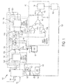
FIG. 1 is an electrical schematic of a digital electro-hydraulic servo valve control system configured to control an electro-hydraulic servo valve according to a non-limiting embodiment. - According to a non-limiting embodiment of the invention, a digitally electronic control system is configured to drive a position of electro-hydraulic servo valve about a plurality of variable positions. The control system includes an electronic field programmable gate array (FPGA) that generates first and second digital pulse width modulation (PWM) signals according to an adjustable duty cycle. An electronic bridge circuit is in electrical communication with the FPGA to convert the first and second digital PWM signals into the bi-polar current signal. The duty cycle of the PWM signals controls the current level of the bi-polar current signal. The control system further includes an electronic current sensing circuit in electrical communication with the bridge circuit. The current sensing circuit is configured to generate a digital feedback signal indicating an average current level of the bi-polar signal. In this manner, the FPGA controls the duty cycle based on at least the average current level indicated by the digital feedback signal. Since the FPGA essentially controls the current level of the bi-polar current signal, a more robust control system is provided that is unaffected by temperature changes and requires less overall operating power.
- With reference now to
FIG. 1 , an electrical schematic of a digital electro-hydraulic servovalve control system 100 is illustrated according to a non-limiting embodiment. The digital electro-hydraulic servovalve control system 100 is configured to generate a first digital pulse-width modulated (PWM)signal 102a and a second digital pulse-width modulated (PWM)signal 102b to control a current level of a servo current signal flowing through an electro-hydraulic servo valve (EHSV) 103. The EHSV 103 is coupled to a surface component and is configured to move about a plurality of positions. The surface component includes, but is not limited to, ailerons (not shown), rudders (not shown), and elevators (not shown). The coil generates an electro-magnetic field in response to an analog bi-polar current signal flowing therethrough. The polarity of the bi-polar current signal dictates the magnetic polarity of the electro-magnetic field, and in turn controls the directional movement of the actuator as understood by one of ordinary skill in the art. Moreover, the movement of the actuator is proportional to the average current level of the bi-polar current flowing through the coil. - The digital electro-hydraulic servo
valve control system 100 includes an electronic field programmable gate array (FPGA) 104, anelectronic bridge circuit 106, an electronicfault detection circuit 108, and an electroniccurrent sensing circuit 110. TheFPGA 104 generates first and second digital pulse width modulation (PWM) signals according to an adjustable duty cycle. TheFPGA 104 may include, for example, an integrated circuit configured to generate the firstdigital PWM signal 102a and thesecond PWM signal 102b according to a variable duty cycle (i.e., pulse width). The FPGA 100 may also include one or more memory elements configured to store data. In this manner, various algorithms and computations can be executed to perform various operations including, but not limited to, storing a desired value and comparing a measured value to the desired value. The FPGA may also be constructed as a gate array that contains up a plurality of logic gates that can be programmed in the field. The FPGA may include not only programmable logic elements, but also programmable interconnects, and switches between the elements. - The
electronic bridge circuit 106 is in electrical communication with theFPGA 104 and is configured to convert the first and seconddigital PWM signals 102a-102b into the bi-polarcurrent signal 112. More specifically, theelectronic bridge circuit 106 includes a plurality of semiconductor switches 114 constructed, for example, as an H-bridge circuit. A first section of the H-bridge circuit 106, i.e., a first set ofsemiconductor switches bridge circuit 106 during a first mode to generate a positive bi-polarcurrent signal 112. A second section of the H-bridge circuit 106, i.e., thesemiconductor switches current signal 112 through the H-bridge circuit 106 when operating in a second mode. The H-bridge circuit 106 may further operate in a third mode which switches off all thesemiconductor switches 114a-114d, thereby disconnecting the bi-polarcurrent signal 112 from theEHSV 103. Accordingly, initiating the third mode of the H-bridge circuit 106 inhibits the bi-polarcurrent signal 112 from flowing through the coil and stops movement of theEHSV 103. - According to a non-limiting embodiment, the H-
bridge circuit 106 includes afirst bridge driver 116a electrically connected between theFPGA 104 and thesemiconductor switches 114a-114b. Asecond bridge driver 116b is electrically connected between theFPGA 104 and thesemiconductor switches 114c-114d. Each of the first andsecond bridge drivers 116a-116b selectively delivers the first andsecond PWM signals 102a-102b to thesemiconductor switches 114a-114d, respectively, to achieve the first and second operating modes of the H-bridge circuit 106. - The
control system 100 includes an electronicfault detection circuit 108 driven by a lowvoltage power supply 120. Thecontrol system 100 further includes afault switch 122 comprising alogic circuit 122. According to a non-limiting embodiment, thelogic gate 122 is an AND gate, where both signals are active high. According to another non-limiting embodiment, thelogic circuit 122 is an OR gate, where both signals are active low. According to a non-limiting embodiment, thefault detection circuit 108 outputs afault signal 124 when the lowvoltage power supply 120 and/or theFPGA 104 outputs a respective fault control signals 126-128. For example, the lowvoltage power supply 120 outputs a "power_good"signal 126 to thelogic circuit 122 if the power falls under an acceptable range of the lowvoltage power supply 120. TheFPGA 104 outputs an "enable" signal 128 when theFPGA 104 is operating properly, and outputs a "disable"signal 128 when a fault exists in the FPGA. In response to receiving thefault signal 124, each of thefirst bridge driver 116a and thesecond bridge driver 116b disconnect thePWM signals 102a-102b from therespective semiconductor switches 114a-114b. Accordingly, a fault occurring in either of theFPGA 104 and/or the lowvoltage power supply 120 is prevented from generating an erroneous bi-polarcurrent signal 112 and improperly moving the actuator of theEHSV 103. - The H-
bridge circuit 106 further includes anelectronic filter unit 130 which is interposed between the H-bridge circuit 106 and the EHSV 103. Theelectronic filter unit 130 includes aresistor 132, and anoise filter 134. Theresistor 132 is connected between thenoise filter 134 and thesemiconductor switches noise filter 134 is connected in parallel with theEHSV 103 and is configured to reduce or eliminate electromagnetic interference from the bi-polarcurrent signal 112. - The
current sensing circuit 110 includes a pair of inputs that receive first and second measured voltages, respectively, and an output that generates adigital feedback signal 136 to theFPGA 104. More specifically, the first input of thecurrent sensing circuit 110 receives a measured voltage taken upstream from theresistor 132, and the second input receives a measured voltage taken downstream from theresistor 132. In this manner, the voltage acrossresistor 132 is measured by thecurrent sensing circuit 110 and is converted into thedigital feedback signal 136 which is output to theFPGA 104 and is utilized to determine the average current of the bi-polarcurrent signal 112 as discussed in greater detail below. Although aresistor 132 is illustrated, is should be appreciated that theresistor 132 can be omitted, and other components can be used to provide the average current of the bi-polarcurrent signal 112 to theEHSV 103 including, but not limited to, a current transformer (not shown). - According to a non-limiting embodiment, the
current sensing circuit 110 includes a pair of buffered operational amplifiers (OPAMPs) 138a-138b and adifferential OPAMP 140. The first bufferedOPAMP 138a receives the first voltage input taken upstream from theresistor 132 and the second bufferedOPAMP 138b receives the second voltage input taken downstream from theresistor 132. The first and second buffered OPAMPs 138a-138b are each configured to increase the common mode range of the first and second voltage inputs, respectively. Thedifferential OPAMP 140 includes a first input that receives the buffered output from thefirst buffer OPAMP 138a and a second input that receives the second buffered output of the second bufferedOPAMP 138b and is configured to output a difference between the first measured voltage taken upstream from theresistor 132 and the second measured voltage taken downstream from theresistor 132. The voltage differential output by thedifference amplifier 140 is proportional to the average current generated by the H-bridge circuit 106, i.e., the bi-polarcurrent signal 112. - The
current sensing signal 110 further includes an offsetOPAMP 142, acurrent clamp circuit 144, and an analog-to-digital (A/D) converter 146. The A/D converter 146 typically has limits as to the input values. For example, the A/D converter 146 may require positive input values being a maximum voltage value. Accordingly, the offsetOPAMP 142 may receive the output from thedifference amplifier 140 and may apply a preset gain to the difference amplifier output, i.e., the measured voltage differential, to maintain the difference OPAMP output in a voltage range that is acceptable for the A/D converter 146. Thecurrent clamp circuit 144 receives the amplified output from the offsetOPAMP 142 and scales the output at a particular polarity, e.g., a positive voltage signal. In this manner, when the H-bridge circuit 106 is operating in the second mode which generates negative current flow, the negative voltage value output from the offsetOPAMP 142 is converted into a positive voltage signal which is then input to the A/D converter 146. According to an embodiment, the offsetOPAMP 142 is configured to convert the bipolar current values into a unipolar current reading having a zero current reading midpoint in the input voltage range of the A/D converter 146. Current readings below the midpoint value represent negative current values while current readings above the midpoint value represent positive current values. - The A/D converter 146 receives the amplified and clamped analog voltage differential and converts the analog voltage differential into a digital signal indicating the voltage differential across
resistor 132. Thedigital signal 136 is then fed back to theFPGA 104 where it is analyzed to determine the average current generated by the H-bridge circuit 106, i.e., the bi-polarcurrent signal 112. For instance, the voltage differential acrossresistor 132 is proportional to the average current generated by the H-bridge circuit 106. Therefore, theFPGA 104 is programmed to execute various algorithms that calculate the average current generated by the H-bridge circuit 106 based on the voltage differential acrossresistor 132 as indicated by thedigital feedback signal 136. - According to a non-limiting embodiment, the
FPGA 104 may receive a desired servo position signal 148 and a currentservo position signal 150. The desired servo position signal 148 is generated by an aircraft control module in response to receiving one or more commands from the aircraft operator. For example, an aircraft operator may input a command that adjusts the position of one or more surface components such as, for example, an aileron. In response to the operator's input, the aircraft control module outputs the desired servo position signal 148 which indicates the desired position of the corresponding surface component. The surface component may include one or more sensors that output the actualservo position signal 150, which represents the actual position of the corresponding surface component. In order to move theEHSV 103 to achieve the desired position indicated by the desiredservo position signal 148, theFPGA 104 generates the first orsecond PWM signal 102a-102b. For example, when the surface component is required to be moved in a first direction, theFPGA 104 outputs thefirst PWM signal 102a such that theEHSV 103 is moved in a first direction. When, however, the surface component is required to move in an opposite direction, theFPGA 104 generates thesecond PWM signal 102b such that theEHSV 103 is moved in a second direction opposite the first direction. As described above, each of the first andsecond PWM signals 102a-102b are converted into the analog bi-polarcurrent signal 112 using the H-bridge circuit 106. While the bi-polarcurrent signal 112 drives the movement of theEHSV 103, thecurrent sensing circuit 110 continuously monitors the voltage differential across theresistor 132. In this manner, theFPGA 104 continuously monitors the average current of the bi-polarcurrent signal 112. When the actual servo position signal 150 matches or substantially matches the desiredservo position signal 148, theFPGA 104 disconnects the first andsecond PWM signals 102a-102b such that movement of theEHSV 103 is stopped and the surface component is maintained in the desired position indicated by the desiredservo position signal 148. - The
EHSV 103control system 100, according to various embodiments of the invention, provides lower costs and higher accuracy when compared to conventional control systems utilizing only an analog approach. Moreover, since thedigital EHSV 103control system 100 eliminates various analog components, the overall size of the circuit board can be reduced. Furthermore, since the FPGA essentially performs an internal execution of the control loop to determine the average current of the bi-polarcurrent signal 112, a morerobust EHSV 103 control system is provided that is less susceptible to the errors and inaccuracies caused by temperature changes realized during flight operation. - While the invention has been described in detail in connection with only a limited number of embodiments, it should be readily understood that the invention is not limited to such disclosed embodiments. Rather, the invention can be modified to incorporate any number of variations, alterations or substitutions, not heretofore described, but which are commensurate with the scope of the invention. Additionally, while various embodiments of the invention have been described, it is to be understood that aspects of the invention may include only some of the described embodiments. Accordingly, the invention is not to be seen as limited by the foregoing description, but is only limited by the scope of the appended claims.
- According to the descriptions above, term "module", as used herein, refers to logic embodied in hardware or firmware, or to a collection of computer readable software instructions, written in a programming language including, but not limited to, Java, C, or assembly, and which is executed by one or more electronic microprocessors. One or more software instructions in the modules may be embedded in firmware, such as, for example, in an EPROM, and/or stored in any type of non-transitory computer-readable medium or other storage device.
Claims (15)
- A control system (100) comprising:an electro-hydraulic servo valve configured to move about a plurality of positions in response to receiving an analog bi-polar current signal;an electronic field programmable gate array (FPGA) (104)that generates first and second digital pulse width modulation (PWM) signals according to an adjustable duty cycle;an electronic bridge circuit (106) in electrical communication with the FPGA to convert the first and second digital PWM signals into the bi-polar current signal; andan electronic current sensing circuit (110) in electrical communication with the bridge circuit (106), the current sensing circuit configured to generate a digital feedback signal indicating an average current level of the bi-polar signal,wherein the FPGA controls the duty cycle based on at least the average current level indicated by the digital feedback signal.
- The control system of claim 1, wherein the electronic bridge circuit (106) is configured to drive a plurality of switching devices that output the bi-polar current signal in response to the first and second PWM signals, the duty cycle of the PWM signals controlling the average current level of the bi-polar current signal.
- The control system of claim 2, wherein the plurality of switching devices are configured as an H-bridge circuit, a first section of the plurality of switching devices generating the bi-polar current signal having a first polarity to move the electro-hydraulic servo valve in a first direction and a second section of the plurality of switching devices generating the bi-polar current signal having a second polarity opposite the first direction to move the electro-hydraulic servo valve in a second direction opposite the first direction.
- The control system of claim 3, further comprising an electronic filter unit interposed between the H-bridge circuit and the electro-hydraulic servo valve.
- The control system of claim 4, wherein the electronic current sensing circuit measures a voltage differential corresponding to the bi-polar current signal and generates an offset analog average current level signal indicating the average current level of the bi-polar current signal based on the voltage differential.
- The control system of claim 5, wherein the electronic current sensing circuit further comprises an analog-to-digital converter that converts the analog average current level signal into the digital feedback signal, and further comprises an offset circuit that converts an analog average current level signal to a midpoint of an input value that is input to the analog-to-digital converter to determine negative current values below the midpoint and positive current values above the midpoint value.
- The control system of claim 6, further comprising an electronic current clamping circuit that limits a range of input values that are input to the analog-to-digital converter.
- The control system of claim 7, further comprising an electronic fault detection circuit (108) in electrical communication with the FPGA and the H-bridge circuit, the fault detection circuit (108) configured to output a fault signal in response to detecting at least one fault corresponding to a low-voltage power supply or a fault corresponding to the FPGA.
- The control system of claim 8, wherein the H-bridge circuit is switched off in response receiving the fault signal such that the bi-polar current signal is disconnected from the electro-hydraulic servo valve.
- The control system of claim 2, wherein the FPGA receives a position signal indicating a position of the electro-hydraulic servo valve, and adjusts the duty cycle based on the digital feedback signal and the position signal.
- A method of controlling an electro-hydraulic servo valve configured to move about a plurality of positions, the method comprising:generating first and second digital pulse width modulation (PWM) signals according to an adjustable duty cycle;electronically converting the first and second digital PWM signals into an analog bi-polar current signal that drives movement of the electro-hydraulic servo valve;generating a digital feedback signal indicating an average current level of the bi-polar signal; andcontrolling the duty cycle based on at least the average current level indicated by the digital feedback signal.
- The method of claim 11, further comprising electrically driving a plurality of switching devices that output the bi-polar current signal in response to the first and second PWM signals, and controlling the average current level of the bi-polar current signal based on the duty cycle of the PWM signals.
- The method of claim 12, generating a first portion of the bi-polar current signal having a first polarity to move the electro-hydraulic servo valve in a first direction in response to electrically driving a first section of the plurality of switching devices generating, and generating a second portion of the bi-polar current signal having a second polarity opposite the first direction to move the electro-hydraulic servo valve in a second direction opposite the first direction in response to electrically driving a second section of the plurality of switching devices.
- The method of claim 13, further comprising filtering electrical noise from the bi-polar current signal using an electronic filter unit interposed between the H-bridge circuit and the electro-hydraulic servo valve.
- The method of claim 14, further comprising measuring a voltage differential corresponding to the bi-polar current signal, and generating an analog average current level signal indicating the average current level of the bi-polar current signal based on the voltage differential.
Applications Claiming Priority (1)
| Application Number | Priority Date | Filing Date | Title |
|---|---|---|---|
| US14/683,613 US10114386B2 (en) | 2015-04-10 | 2015-04-10 | Electro-hydraulic servo valve control system |
Publications (3)
| Publication Number | Publication Date |
|---|---|
| EP3081480A2 true EP3081480A2 (en) | 2016-10-19 |
| EP3081480A3 EP3081480A3 (en) | 2016-11-23 |
| EP3081480B1 EP3081480B1 (en) | 2021-03-24 |
Family
ID=55745590
Family Applications (1)
| Application Number | Title | Priority Date | Filing Date |
|---|---|---|---|
| EP16164384.6A Active EP3081480B1 (en) | 2015-04-10 | 2016-04-08 | Electro-hydraulic servo valve control system |
Country Status (2)
| Country | Link |
|---|---|
| US (1) | US10114386B2 (en) |
| EP (1) | EP3081480B1 (en) |
Cited By (3)
| Publication number | Priority date | Publication date | Assignee | Title |
|---|---|---|---|---|
| CN107479430A (en) * | 2016-11-21 | 2017-12-15 | 北京驰亿隆科技有限公司 | A kind of gearbox driving circuit for electromagnetic valve and its control method |
| US11428247B2 (en) | 2020-02-07 | 2022-08-30 | Woodward, Inc. | Electro-hydraulic servovalve control with input |
| US11796990B2 (en) | 2021-08-24 | 2023-10-24 | Woodward, Inc. | Model based monitoring of faults in electro-hydraulic valves |
Families Citing this family (7)
| Publication number | Priority date | Publication date | Assignee | Title |
|---|---|---|---|---|
| GB2586082A (en) | 2019-08-02 | 2021-02-03 | Airbus Operations Ltd | Avionics unit |
| US12556115B2 (en) | 2020-06-03 | 2026-02-17 | Woodward, Inc. | Reduction of current ripple due to MOSFET switching delays in PWM-based drives |
| CN113377619B (en) * | 2021-06-21 | 2024-12-20 | 唐堃 | A server motherboard monitoring management system and method based on FPGA |
| CN113607405B (en) * | 2021-07-28 | 2022-07-29 | 燕山大学 | Digital valve group multi-fault detection device and diagnosis method thereof |
| US12247594B2 (en) * | 2022-02-11 | 2025-03-11 | Hamilton Sundstrand Corporation | Pulse width modulated control of servo |
| US12055960B2 (en) * | 2022-03-23 | 2024-08-06 | General Electric Company | Split valves for regulating fluid flow in closed loop systems |
| CN116480655B (en) * | 2023-04-11 | 2026-05-12 | 北京瑞赛长城航空测控技术有限公司 | Simulation device of electrohydraulic servo control system |
Family Cites Families (12)
| Publication number | Priority date | Publication date | Assignee | Title |
|---|---|---|---|---|
| US3757183A (en) * | 1972-03-30 | 1973-09-04 | Nasa | Redundant speed control for brushless hall effect motor |
| US4794312A (en) * | 1986-09-29 | 1988-12-27 | Hitachi, Ltd. | Method and apparatus for controlling a servo motor |
| US5722460A (en) * | 1996-10-10 | 1998-03-03 | Olsen Controls, Inc. | Digital servo valve system |
| US6034499A (en) | 1997-04-01 | 2000-03-07 | Tranovich; Stephen J. | Method of controlling rotary position of a torque motor |
| DE102004014767A1 (en) * | 2004-03-26 | 2005-10-06 | Mtu Aero Engines Gmbh | Circuit arrangement for aircraft engine controller |
| JP4687730B2 (en) * | 2008-03-06 | 2011-05-25 | パナソニック株式会社 | Blower and electric device equipped with the same |
| CN101576745B (en) | 2009-06-09 | 2011-04-13 | 北京航空航天大学 | Full digital driving controller of permanent magnetic linear voice coil motor used for direct driving valve |
| GB201002815D0 (en) * | 2010-02-18 | 2010-04-07 | New Led Light Ltd | Automated energy saver led power supply system |
| EP2605616B1 (en) * | 2011-12-13 | 2016-03-02 | Samsung Electronics Co., Ltd. | Induction heating fusing device and image forming apparatus |
| CN102801379A (en) | 2012-08-08 | 2012-11-28 | 中国科学院长春光学精密机械与物理研究所 | Universal full-digital direct-current motor servo driver |
| US9732736B2 (en) * | 2013-04-15 | 2017-08-15 | GM Global Technology Operations LLC | System and method for controlling an active material actuator |
| US9077321B2 (en) * | 2013-10-23 | 2015-07-07 | Corning Optical Communications Wireless Ltd. | Variable amplitude signal generators for generating a sinusoidal signal having limited direct current (DC) offset variation, and related devices, systems, and methods |
-
2015
- 2015-04-10 US US14/683,613 patent/US10114386B2/en active Active
-
2016
- 2016-04-08 EP EP16164384.6A patent/EP3081480B1/en active Active
Non-Patent Citations (1)
| Title |
|---|
| None |
Cited By (4)
| Publication number | Priority date | Publication date | Assignee | Title |
|---|---|---|---|---|
| CN107479430A (en) * | 2016-11-21 | 2017-12-15 | 北京驰亿隆科技有限公司 | A kind of gearbox driving circuit for electromagnetic valve and its control method |
| CN107479430B (en) * | 2016-11-21 | 2020-07-28 | 北京驰亿隆科技有限公司 | Gearbox electromagnetic valve driving circuit and control method thereof |
| US11428247B2 (en) | 2020-02-07 | 2022-08-30 | Woodward, Inc. | Electro-hydraulic servovalve control with input |
| US11796990B2 (en) | 2021-08-24 | 2023-10-24 | Woodward, Inc. | Model based monitoring of faults in electro-hydraulic valves |
Also Published As
| Publication number | Publication date |
|---|---|
| EP3081480B1 (en) | 2021-03-24 |
| EP3081480A3 (en) | 2016-11-23 |
| US20160299512A1 (en) | 2016-10-13 |
| US10114386B2 (en) | 2018-10-30 |
Similar Documents
| Publication | Publication Date | Title |
|---|---|---|
| EP3081480B1 (en) | Electro-hydraulic servo valve control system | |
| US10066610B2 (en) | Tilting angle control device | |
| KR20210075479A (en) | Sensor fault diagnosis system for converter | |
| EP2527248B1 (en) | Suppressing electrical failure effects in servo control systems | |
| EP2320547B1 (en) | Current-controlled semiconductor device and control unit using the same | |
| EP2343613A2 (en) | Flight control system | |
| US10476391B2 (en) | Voltage converting device | |
| KR102404127B1 (en) | Control device for DC converter, DC converter, and control method of DC converter | |
| WO2017027792A1 (en) | Method and apparatus for solenoid position measurement and control | |
| US20100318245A1 (en) | Flight control system | |
| US9035658B2 (en) | Method for detecting a breakdown in a switching current source and corresponding power source | |
| EP3309395A1 (en) | Driving system for piezoelectric pump | |
| US9281767B2 (en) | Motor driving apparatus | |
| CN102107731A (en) | Actuator control system | |
| EP3026446B1 (en) | Electrical current system including voltage drop component | |
| CN211145517U (en) | A control system for proportional solenoid valve and proportional solenoid valve | |
| US7932689B2 (en) | Motor drive system for driving motor provided with a plurality of windings | |
| CN113014095B (en) | Intelligent chopping system for magnetic suspension train | |
| US12493073B2 (en) | Test arrangement for testing a power electronics controller | |
| JPH11247807A (en) | Servo valve | |
| KR101753476B1 (en) | Apparatus and method for driving motor | |
| JP2010119041A (en) | Analog output device | |
| US11824528B2 (en) | Load drive device and control method of load drive device | |
| JP7056393B2 (en) | Voltage transducer | |
| CN113098363A (en) | Control apparatus and control method |
Legal Events
| Date | Code | Title | Description |
|---|---|---|---|
| PUAI | Public reference made under article 153(3) epc to a published international application that has entered the european phase |
Free format text: ORIGINAL CODE: 0009012 |
|
| AK | Designated contracting states |
Kind code of ref document: A2 Designated state(s): AL AT BE BG CH CY CZ DE DK EE ES FI FR GB GR HR HU IE IS IT LI LT LU LV MC MK MT NL NO PL PT RO RS SE SI SK SM TR |
|
| AX | Request for extension of the european patent |
Extension state: BA ME |
|
| PUAL | Search report despatched |
Free format text: ORIGINAL CODE: 0009013 |
|
| AK | Designated contracting states |
Kind code of ref document: A3 Designated state(s): AL AT BE BG CH CY CZ DE DK EE ES FI FR GB GR HR HU IE IS IT LI LT LU LV MC MK MT NL NO PL PT RO RS SE SI SK SM TR |
|
| AX | Request for extension of the european patent |
Extension state: BA ME |
|
| RIC1 | Information provided on ipc code assigned before grant |
Ipc: B64C 13/00 20060101AFI20161017BHEP Ipc: H02M 7/5387 20070101ALI20161017BHEP Ipc: G05B 19/46 20060101ALI20161017BHEP |
|
| STAA | Information on the status of an ep patent application or granted ep patent |
Free format text: STATUS: REQUEST FOR EXAMINATION WAS MADE |
|
| 17P | Request for examination filed |
Effective date: 20170523 |
|
| RBV | Designated contracting states (corrected) |
Designated state(s): AL AT BE BG CH CY CZ DE DK EE ES FI FR GB GR HR HU IE IS IT LI LT LU LV MC MK MT NL NO PL PT RO RS SE SI SK SM TR |
|
| STAA | Information on the status of an ep patent application or granted ep patent |
Free format text: STATUS: EXAMINATION IS IN PROGRESS |
|
| 17Q | First examination report despatched |
Effective date: 20180419 |
|
| REG | Reference to a national code |
Ref country code: DE Ref legal event code: R079 Ref document number: 602016054705 Country of ref document: DE Free format text: PREVIOUS MAIN CLASS: B64C0013000000 Ipc: G05B0019460000 |
|
| GRAP | Despatch of communication of intention to grant a patent |
Free format text: ORIGINAL CODE: EPIDOSNIGR1 |
|
| STAA | Information on the status of an ep patent application or granted ep patent |
Free format text: STATUS: GRANT OF PATENT IS INTENDED |
|
| RIC1 | Information provided on ipc code assigned before grant |
Ipc: B64C 13/40 20060101ALI20201005BHEP Ipc: H02M 7/5387 20070101ALI20201005BHEP Ipc: G05B 19/46 20060101AFI20201005BHEP Ipc: B64C 13/50 20060101ALI20201005BHEP |
|
| INTG | Intention to grant announced |
Effective date: 20201026 |
|
| GRAS | Grant fee paid |
Free format text: ORIGINAL CODE: EPIDOSNIGR3 |
|
| GRAA | (expected) grant |
Free format text: ORIGINAL CODE: 0009210 |
|
| STAA | Information on the status of an ep patent application or granted ep patent |
Free format text: STATUS: THE PATENT HAS BEEN GRANTED |
|
| AK | Designated contracting states |
Kind code of ref document: B1 Designated state(s): AL AT BE BG CH CY CZ DE DK EE ES FI FR GB GR HR HU IE IS IT LI LT LU LV MC MK MT NL NO PL PT RO RS SE SI SK SM TR |
|
| REG | Reference to a national code |
Ref country code: GB Ref legal event code: FG4D |
|
| REG | Reference to a national code |
Ref country code: CH Ref legal event code: EP |
|
| REG | Reference to a national code |
Ref country code: DE Ref legal event code: R096 Ref document number: 602016054705 Country of ref document: DE |
|
| REG | Reference to a national code |
Ref country code: IE Ref legal event code: FG4D |
|
| REG | Reference to a national code |
Ref country code: AT Ref legal event code: REF Ref document number: 1375114 Country of ref document: AT Kind code of ref document: T Effective date: 20210415 |
|
| REG | Reference to a national code |
Ref country code: LT Ref legal event code: MG9D |
|
| PG25 | Lapsed in a contracting state [announced via postgrant information from national office to epo] |
Ref country code: BG Free format text: LAPSE BECAUSE OF FAILURE TO SUBMIT A TRANSLATION OF THE DESCRIPTION OR TO PAY THE FEE WITHIN THE PRESCRIBED TIME-LIMIT Effective date: 20210624 Ref country code: FI Free format text: LAPSE BECAUSE OF FAILURE TO SUBMIT A TRANSLATION OF THE DESCRIPTION OR TO PAY THE FEE WITHIN THE PRESCRIBED TIME-LIMIT Effective date: 20210324 Ref country code: GR Free format text: LAPSE BECAUSE OF FAILURE TO SUBMIT A TRANSLATION OF THE DESCRIPTION OR TO PAY THE FEE WITHIN THE PRESCRIBED TIME-LIMIT Effective date: 20210625 Ref country code: HR Free format text: LAPSE BECAUSE OF FAILURE TO SUBMIT A TRANSLATION OF THE DESCRIPTION OR TO PAY THE FEE WITHIN THE PRESCRIBED TIME-LIMIT Effective date: 20210324 Ref country code: NO Free format text: LAPSE BECAUSE OF FAILURE TO SUBMIT A TRANSLATION OF THE DESCRIPTION OR TO PAY THE FEE WITHIN THE PRESCRIBED TIME-LIMIT Effective date: 20210624 |
|
| PG25 | Lapsed in a contracting state [announced via postgrant information from national office to epo] |
Ref country code: SE Free format text: LAPSE BECAUSE OF FAILURE TO SUBMIT A TRANSLATION OF THE DESCRIPTION OR TO PAY THE FEE WITHIN THE PRESCRIBED TIME-LIMIT Effective date: 20210324 Ref country code: RS Free format text: LAPSE BECAUSE OF FAILURE TO SUBMIT A TRANSLATION OF THE DESCRIPTION OR TO PAY THE FEE WITHIN THE PRESCRIBED TIME-LIMIT Effective date: 20210324 Ref country code: LV Free format text: LAPSE BECAUSE OF FAILURE TO SUBMIT A TRANSLATION OF THE DESCRIPTION OR TO PAY THE FEE WITHIN THE PRESCRIBED TIME-LIMIT Effective date: 20210324 |
|
| REG | Reference to a national code |
Ref country code: NL Ref legal event code: MP Effective date: 20210324 |
|
| REG | Reference to a national code |
Ref country code: AT Ref legal event code: MK05 Ref document number: 1375114 Country of ref document: AT Kind code of ref document: T Effective date: 20210324 |
|
| PG25 | Lapsed in a contracting state [announced via postgrant information from national office to epo] |
Ref country code: NL Free format text: LAPSE BECAUSE OF FAILURE TO SUBMIT A TRANSLATION OF THE DESCRIPTION OR TO PAY THE FEE WITHIN THE PRESCRIBED TIME-LIMIT Effective date: 20210324 |
|
| PG25 | Lapsed in a contracting state [announced via postgrant information from national office to epo] |
Ref country code: SM Free format text: LAPSE BECAUSE OF FAILURE TO SUBMIT A TRANSLATION OF THE DESCRIPTION OR TO PAY THE FEE WITHIN THE PRESCRIBED TIME-LIMIT Effective date: 20210324 Ref country code: AT Free format text: LAPSE BECAUSE OF FAILURE TO SUBMIT A TRANSLATION OF THE DESCRIPTION OR TO PAY THE FEE WITHIN THE PRESCRIBED TIME-LIMIT Effective date: 20210324 Ref country code: LT Free format text: LAPSE BECAUSE OF FAILURE TO SUBMIT A TRANSLATION OF THE DESCRIPTION OR TO PAY THE FEE WITHIN THE PRESCRIBED TIME-LIMIT Effective date: 20210324 Ref country code: EE Free format text: LAPSE BECAUSE OF FAILURE TO SUBMIT A TRANSLATION OF THE DESCRIPTION OR TO PAY THE FEE WITHIN THE PRESCRIBED TIME-LIMIT Effective date: 20210324 Ref country code: CZ Free format text: LAPSE BECAUSE OF FAILURE TO SUBMIT A TRANSLATION OF THE DESCRIPTION OR TO PAY THE FEE WITHIN THE PRESCRIBED TIME-LIMIT Effective date: 20210324 |
|
| PG25 | Lapsed in a contracting state [announced via postgrant information from national office to epo] |
Ref country code: IS Free format text: LAPSE BECAUSE OF FAILURE TO SUBMIT A TRANSLATION OF THE DESCRIPTION OR TO PAY THE FEE WITHIN THE PRESCRIBED TIME-LIMIT Effective date: 20210724 Ref country code: RO Free format text: LAPSE BECAUSE OF FAILURE TO SUBMIT A TRANSLATION OF THE DESCRIPTION OR TO PAY THE FEE WITHIN THE PRESCRIBED TIME-LIMIT Effective date: 20210324 Ref country code: SK Free format text: LAPSE BECAUSE OF FAILURE TO SUBMIT A TRANSLATION OF THE DESCRIPTION OR TO PAY THE FEE WITHIN THE PRESCRIBED TIME-LIMIT Effective date: 20210324 Ref country code: ES Free format text: LAPSE BECAUSE OF FAILURE TO SUBMIT A TRANSLATION OF THE DESCRIPTION OR TO PAY THE FEE WITHIN THE PRESCRIBED TIME-LIMIT Effective date: 20210324 Ref country code: PL Free format text: LAPSE BECAUSE OF FAILURE TO SUBMIT A TRANSLATION OF THE DESCRIPTION OR TO PAY THE FEE WITHIN THE PRESCRIBED TIME-LIMIT Effective date: 20210324 Ref country code: PT Free format text: LAPSE BECAUSE OF FAILURE TO SUBMIT A TRANSLATION OF THE DESCRIPTION OR TO PAY THE FEE WITHIN THE PRESCRIBED TIME-LIMIT Effective date: 20210726 |
|
| PG25 | Lapsed in a contracting state [announced via postgrant information from national office to epo] |
Ref country code: LU Free format text: LAPSE BECAUSE OF NON-PAYMENT OF DUE FEES Effective date: 20210408 |
|
| REG | Reference to a national code |
Ref country code: DE Ref legal event code: R097 Ref document number: 602016054705 Country of ref document: DE |
|
| REG | Reference to a national code |
Ref country code: BE Ref legal event code: MM Effective date: 20210430 |
|
| PG25 | Lapsed in a contracting state [announced via postgrant information from national office to epo] |
Ref country code: DK Free format text: LAPSE BECAUSE OF FAILURE TO SUBMIT A TRANSLATION OF THE DESCRIPTION OR TO PAY THE FEE WITHIN THE PRESCRIBED TIME-LIMIT Effective date: 20210324 Ref country code: CH Free format text: LAPSE BECAUSE OF NON-PAYMENT OF DUE FEES Effective date: 20210430 Ref country code: AL Free format text: LAPSE BECAUSE OF FAILURE TO SUBMIT A TRANSLATION OF THE DESCRIPTION OR TO PAY THE FEE WITHIN THE PRESCRIBED TIME-LIMIT Effective date: 20210324 Ref country code: MC Free format text: LAPSE BECAUSE OF FAILURE TO SUBMIT A TRANSLATION OF THE DESCRIPTION OR TO PAY THE FEE WITHIN THE PRESCRIBED TIME-LIMIT Effective date: 20210324 Ref country code: LI Free format text: LAPSE BECAUSE OF NON-PAYMENT OF DUE FEES Effective date: 20210430 |
|
| PLBE | No opposition filed within time limit |
Free format text: ORIGINAL CODE: 0009261 |
|
| STAA | Information on the status of an ep patent application or granted ep patent |
Free format text: STATUS: NO OPPOSITION FILED WITHIN TIME LIMIT |
|
| PG25 | Lapsed in a contracting state [announced via postgrant information from national office to epo] |
Ref country code: SI Free format text: LAPSE BECAUSE OF FAILURE TO SUBMIT A TRANSLATION OF THE DESCRIPTION OR TO PAY THE FEE WITHIN THE PRESCRIBED TIME-LIMIT Effective date: 20210324 |
|
| 26N | No opposition filed |
Effective date: 20220104 |
|
| PG25 | Lapsed in a contracting state [announced via postgrant information from national office to epo] |
Ref country code: IE Free format text: LAPSE BECAUSE OF NON-PAYMENT OF DUE FEES Effective date: 20210408 |
|
| PG25 | Lapsed in a contracting state [announced via postgrant information from national office to epo] |
Ref country code: IS Free format text: LAPSE BECAUSE OF FAILURE TO SUBMIT A TRANSLATION OF THE DESCRIPTION OR TO PAY THE FEE WITHIN THE PRESCRIBED TIME-LIMIT Effective date: 20210724 |
|
| PG25 | Lapsed in a contracting state [announced via postgrant information from national office to epo] |
Ref country code: BE Free format text: LAPSE BECAUSE OF NON-PAYMENT OF DUE FEES Effective date: 20210430 |
|
| PG25 | Lapsed in a contracting state [announced via postgrant information from national office to epo] |
Ref country code: IT Free format text: LAPSE BECAUSE OF FAILURE TO SUBMIT A TRANSLATION OF THE DESCRIPTION OR TO PAY THE FEE WITHIN THE PRESCRIBED TIME-LIMIT Effective date: 20210324 |
|
| PG25 | Lapsed in a contracting state [announced via postgrant information from national office to epo] |
Ref country code: HU Free format text: LAPSE BECAUSE OF FAILURE TO SUBMIT A TRANSLATION OF THE DESCRIPTION OR TO PAY THE FEE WITHIN THE PRESCRIBED TIME-LIMIT; INVALID AB INITIO Effective date: 20160408 |
|
| P01 | Opt-out of the competence of the unified patent court (upc) registered |
Effective date: 20230522 |
|
| PG25 | Lapsed in a contracting state [announced via postgrant information from national office to epo] |
Ref country code: CY Free format text: LAPSE BECAUSE OF FAILURE TO SUBMIT A TRANSLATION OF THE DESCRIPTION OR TO PAY THE FEE WITHIN THE PRESCRIBED TIME-LIMIT Effective date: 20210324 |
|
| PG25 | Lapsed in a contracting state [announced via postgrant information from national office to epo] |
Ref country code: MK Free format text: LAPSE BECAUSE OF FAILURE TO SUBMIT A TRANSLATION OF THE DESCRIPTION OR TO PAY THE FEE WITHIN THE PRESCRIBED TIME-LIMIT Effective date: 20210324 |
|
| PG25 | Lapsed in a contracting state [announced via postgrant information from national office to epo] |
Ref country code: MT Free format text: LAPSE BECAUSE OF FAILURE TO SUBMIT A TRANSLATION OF THE DESCRIPTION OR TO PAY THE FEE WITHIN THE PRESCRIBED TIME-LIMIT Effective date: 20210324 |
|
| PGFP | Annual fee paid to national office [announced via postgrant information from national office to epo] |
Ref country code: FR Payment date: 20250319 Year of fee payment: 10 |
|
| PGFP | Annual fee paid to national office [announced via postgrant information from national office to epo] |
Ref country code: DE Payment date: 20250319 Year of fee payment: 10 |
|
| PG25 | Lapsed in a contracting state [announced via postgrant information from national office to epo] |
Ref country code: TR Free format text: LAPSE BECAUSE OF FAILURE TO SUBMIT A TRANSLATION OF THE DESCRIPTION OR TO PAY THE FEE WITHIN THE PRESCRIBED TIME-LIMIT Effective date: 20210324 |
|
| PGFP | Annual fee paid to national office [announced via postgrant information from national office to epo] |
Ref country code: GB Payment date: 20260327 Year of fee payment: 11 |