EP3081443A1 - Flat wiper blade - Google Patents
Flat wiper blade Download PDFInfo
- Publication number
- EP3081443A1 EP3081443A1 EP16172013.1A EP16172013A EP3081443A1 EP 3081443 A1 EP3081443 A1 EP 3081443A1 EP 16172013 A EP16172013 A EP 16172013A EP 3081443 A1 EP3081443 A1 EP 3081443A1
- Authority
- EP
- European Patent Office
- Prior art keywords
- wiper blade
- injection
- spoiler
- jet
- washing
- Prior art date
- Legal status (The legal status is an assumption and is not a legal conclusion. Google has not performed a legal analysis and makes no representation as to the accuracy of the status listed.)
- Granted
Links
Images


Classifications
-
- B—PERFORMING OPERATIONS; TRANSPORTING
- B60—VEHICLES IN GENERAL
- B60S—SERVICING, CLEANING, REPAIRING, SUPPORTING, LIFTING, OR MANOEUVRING OF VEHICLES, NOT OTHERWISE PROVIDED FOR
- B60S1/00—Cleaning of vehicles
- B60S1/02—Cleaning windscreens, windows or optical devices
- B60S1/46—Cleaning windscreens, windows or optical devices using liquid; Windscreen washers
- B60S1/48—Liquid supply therefor
- B60S1/52—Arrangement of nozzles; Liquid spreading means
- B60S1/522—Arrangement of nozzles; Liquid spreading means moving liquid spreading means, e.g. arranged in wiper arms
- B60S1/524—Arrangement of nozzles; Liquid spreading means moving liquid spreading means, e.g. arranged in wiper arms arranged in wiper blades
-
- B—PERFORMING OPERATIONS; TRANSPORTING
- B60—VEHICLES IN GENERAL
- B60S—SERVICING, CLEANING, REPAIRING, SUPPORTING, LIFTING, OR MANOEUVRING OF VEHICLES, NOT OTHERWISE PROVIDED FOR
- B60S1/00—Cleaning of vehicles
- B60S1/02—Cleaning windscreens, windows or optical devices
- B60S1/04—Wipers or the like, e.g. scrapers
- B60S1/32—Wipers or the like, e.g. scrapers characterised by constructional features of wiper blade arms or blades
- B60S1/38—Wiper blades
- B60S1/3803—Wiper blades heated wiper blades
- B60S1/3805—Wiper blades heated wiper blades electrically
-
- B—PERFORMING OPERATIONS; TRANSPORTING
- B60—VEHICLES IN GENERAL
- B60S—SERVICING, CLEANING, REPAIRING, SUPPORTING, LIFTING, OR MANOEUVRING OF VEHICLES, NOT OTHERWISE PROVIDED FOR
- B60S1/00—Cleaning of vehicles
- B60S1/02—Cleaning windscreens, windows or optical devices
- B60S1/04—Wipers or the like, e.g. scrapers
- B60S1/32—Wipers or the like, e.g. scrapers characterised by constructional features of wiper blade arms or blades
- B60S1/38—Wiper blades
- B60S1/3806—Means, or measures taken, for influencing the aerodynamic quality of the wiper blades
- B60S1/3808—Spoiler integral with the squeegee
-
- B—PERFORMING OPERATIONS; TRANSPORTING
- B60—VEHICLES IN GENERAL
- B60S—SERVICING, CLEANING, REPAIRING, SUPPORTING, LIFTING, OR MANOEUVRING OF VEHICLES, NOT OTHERWISE PROVIDED FOR
- B60S1/00—Cleaning of vehicles
- B60S1/02—Cleaning windscreens, windows or optical devices
- B60S1/04—Wipers or the like, e.g. scrapers
- B60S1/32—Wipers or the like, e.g. scrapers characterised by constructional features of wiper blade arms or blades
- B60S1/38—Wiper blades
- B60S1/3806—Means, or measures taken, for influencing the aerodynamic quality of the wiper blades
- B60S1/381—Spoilers mounted on the squeegee or on the vertebra
-
- B—PERFORMING OPERATIONS; TRANSPORTING
- B60—VEHICLES IN GENERAL
- B60S—SERVICING, CLEANING, REPAIRING, SUPPORTING, LIFTING, OR MANOEUVRING OF VEHICLES, NOT OTHERWISE PROVIDED FOR
- B60S1/00—Cleaning of vehicles
- B60S1/02—Cleaning windscreens, windows or optical devices
- B60S1/04—Wipers or the like, e.g. scrapers
- B60S1/32—Wipers or the like, e.g. scrapers characterised by constructional features of wiper blade arms or blades
- B60S1/38—Wiper blades
- B60S1/3848—Flat-type wiper blade, i.e. without harness
- B60S1/3849—Connectors therefor; Connection to wiper arm; Attached to blade
- B60S1/3862—Transport of liquid there through
-
- B—PERFORMING OPERATIONS; TRANSPORTING
- B60—VEHICLES IN GENERAL
- B60S—SERVICING, CLEANING, REPAIRING, SUPPORTING, LIFTING, OR MANOEUVRING OF VEHICLES, NOT OTHERWISE PROVIDED FOR
- B60S1/00—Cleaning of vehicles
- B60S1/02—Cleaning windscreens, windows or optical devices
- B60S1/04—Wipers or the like, e.g. scrapers
- B60S1/32—Wipers or the like, e.g. scrapers characterised by constructional features of wiper blade arms or blades
- B60S1/38—Wiper blades
- B60S1/3848—Flat-type wiper blade, i.e. without harness
- B60S1/3886—End caps
-
- B—PERFORMING OPERATIONS; TRANSPORTING
- B60—VEHICLES IN GENERAL
- B60S—SERVICING, CLEANING, REPAIRING, SUPPORTING, LIFTING, OR MANOEUVRING OF VEHICLES, NOT OTHERWISE PROVIDED FOR
- B60S1/00—Cleaning of vehicles
- B60S1/02—Cleaning windscreens, windows or optical devices
- B60S1/04—Wipers or the like, e.g. scrapers
- B60S1/32—Wipers or the like, e.g. scrapers characterised by constructional features of wiper blade arms or blades
- B60S1/40—Connections between blades and arms
- B60S1/42—Connections between blades and arms resilient
-
- B—PERFORMING OPERATIONS; TRANSPORTING
- B60—VEHICLES IN GENERAL
- B60S—SERVICING, CLEANING, REPAIRING, SUPPORTING, LIFTING, OR MANOEUVRING OF VEHICLES, NOT OTHERWISE PROVIDED FOR
- B60S1/00—Cleaning of vehicles
- B60S1/02—Cleaning windscreens, windows or optical devices
- B60S1/04—Wipers or the like, e.g. scrapers
- B60S1/32—Wipers or the like, e.g. scrapers characterised by constructional features of wiper blade arms or blades
- B60S1/38—Wiper blades
- B60S1/3848—Flat-type wiper blade, i.e. without harness
- B60S1/3874—Flat-type wiper blade, i.e. without harness with a reinforcing vertebra
- B60S1/3875—Flat-type wiper blade, i.e. without harness with a reinforcing vertebra rectangular section
- B60S1/3879—Flat-type wiper blade, i.e. without harness with a reinforcing vertebra rectangular section placed in side grooves in the squeegee
Definitions
- the invention refers to a flat wiper blade according to the generic term in patent claim 1 or 8 and in this case specifically to a flat wiper blade having at least one injection or washing duct on at least one longitudinal side of the wiper blade, presenting a large number of jet or injection openings for application of a washing and cleaning fluid to a vehicle windscreen.
- Flat wiper blades are known in various different embodiments.
- Flat wiper blades are also particularly known ( DE 103 35 394 A1 ) having two flat spring rails spaced apart from each other extending in the longitudinal direction of the wiper blade and a wiping rubber forming the wiping lip, wherein the spring rails are respectively received over part of their width in grooves on the longitudinal sides of the wiping rubber and therefore receive the wiping rubber between them in a wiping rubber section remaining between the grooves.
- a profile constructed as a spoiler (spoiler profile) is fixed to the external peripheries of the spring rails facing away from the wiping rubber.
- Flat wiper blades are furthermore known ( DE 10 2006 013 900 A1 ) having a spoiler-like-shaped wiper blade body, formed of a length of a solid plastic profile, which, on the external peripheries of two spring rails facing away from the wiping rubber, is retained spanning these peripheries.
- the wiper blade body is provided on both longitudinal sides of the wiper blade respectively with injection and washing ducts presenting a large number of jet or injection openings. Disadvantageous among other aspects are the high mass and impaired flexibility of the wiper blade determined by the solid, spoiler-like wiper blade body.
- Wiper blades are furthermore known ( DE 10 2007 030 169 A1 ) having a single flat spring rail surrounded by the wiping rubber and with a spoiler profile forming the upper side of the wiper blade, which (spoiler profile) on the profile section of the wiping rubber surrounding the spring rail, is retained positively spanning the wiping rubber in the manner of a slide on the upper side of the wiper blade.
- the flat wiper blade presents on at least one longitudinal side of the wiper blade an injection strip manufactured in one piece with the spoiler profile with an injection and washing duct having a large number of jets or injection openings.
- Flat wiper blades are furthermore known (EP 1 178 807 B1 ) with two spring rails and a wiping rubber received between the spring rails, which forms the wiping lip on the underside of the wiper blade and is constructed shaped as a spoiler, i.e. with a spoiler-like profile section, on the upper side of the wiper blade.
- a jet or injection strip is fixed respectively to the projecting spring rails with an injection or washing duct having a large number of jets or injection openings and to be more precise with a fastening section spanning the external periphery of the spring rail in question in the manner of a clip.
- openings are provided in the projecting spring rails, in which projections on the fastening sections of the jet strips engage and lock.
- Disadvantageous in this case is elaborate assembly owing to a large number of individual components and particularly also the fact that differences in colour in the case of the large number of the individual parts cannot be avoided and therefore the uniform appearance also sought for the colouring of the wiper blade cannot be achieved.
- Flat wiper blades are furthermore known (EP 1 918 167*), presenting an injection or washing duct having a large number of jet or injection openings on a longitudinal side of the wiper blade, with this injection and washing duct being formed of a tube, which is retained by several clip-like fixing elements spaced apart from one another in the longitudinal direction of the wiper blade and spanning the upper side of the wiper blade.
- Disadvantageous in this case is particularly the relatively large amount of expenditure in terms of assembly and the associated high assembly costs due to a large number of individual components.
- the purpose of the invention is to demonstrate a flat wiper blade provided on at least one longitudinal side of the wiper blade with an injection or washing duct having a large number of jet or injection openings and presenting improved visual and/or mechanical properties with simplified assembly.
- At least one spoiler element is provided on the upper side of the wiper blade, which is constructed in one piece with at least one jet or injection strip extending in the assembled state along a longitudinal side of the wiper blade.
- the particularity of the wiper blade in this case lies in the fact that the spoiler element is designed in the manner of a shell and to be more precise in such a manner that for its fastening to both longitudinal sides of the wiper blade, it directly or however indirectly spans the external peripheries of the spring rails.
- the shell-shaped embodiment of the spoiler element a construction of the wiper blade with reduced mass and with a flexibility unimpaired by the spoiler element is possible.
- the shell-like spoiler element possesses a wall thickness that is for example of the order of magnitude of the spring rail thickness, i.e. of the order of magnitude of the thickness of the flat material used to manufacture the spring rails; preferably, the wall thickness of the shell-like spoiler element is at the most identical to or however less than the spring rail thickness.
- the supporting profile is then for example an independent, hollow profile or hollow chamber profile externally retained on the spring rails.
- the shell-like spoiler element is then retained spanning this supporting profile in the area of the spring rails indirectly on this supporting profile.
- the supporting profile may also be formed of a spoiler-like profile section of the wiping rubber itself.
- a jet or injection strip is fixed to at least one longitudinal side of the wiper blade, presenting at least one injection or washing duct with a large number of jet or injection openings for application of the washing and cleaning fluid.
- the jet or injection strip is constructed in one piece with a fastening section, by means of which it is retained on the wiper blade in the area of the external edge of a spring rail and preferably extending over the entire or essentially the entire length of the jet or injection strip.
- the at least one jet or injection strip is secured by several clip-like or clasp-like securing elements spaced apart from one another in the longitudinal direction of the wiper blade, which span the at least one jet or injection strip in addition to the wiper blade on its upper side and are retained positively and preferably by locking on the wiper blade in the area of the spring rails.
- the clip-like or clasp-like securing elements are not an integral part of the at least one jet or injection strip, but independent, thin-walled elements. If the wiper blade is constructed as a spoiler at least in subareas on the upper side of the wiper blade, the clip-like or clasp-like securing elements at this position are adapted in shape to the spoiler profile.
- 1 is the wiper arm of a windscreen wiper module for vehicle windscreens FS, particularly vehicle front windscreens.
- the wiper arm 1 consists in the well known manner of a pivot section 2, by means of which the wiper arm 1 can be mounted on a wiper shaft not illustrated, in addition to a wiper arm element 4 (wiper rod) articulated on the pivot section 2 by means of a wiper arm link 3, which (wiper arm element) is provided on its end distant from the pivot section 2 with an adapter 5 on the wiper arm side for detachable flexible fixing of a wiper blade, for example the wiper blade 6 in Figure 3 .
- the wiper blade 6 is constructed as a flat wiper blade and comprises for this purpose at least two flat spring rails 7, manufactured from a sprung metallic material, for example spring steel, a wiping rubber 8, two spoiler-like-shaped, strip-like supporting elements 9, two shell-like spoiler elements 10 forming the upper side of the wiper blade 6, in addition to a wiper blade adapter 11 for detachable flexible connection to the adapter 5.
- a sprung metallic material for example spring steel
- a wiping rubber 8 two spoiler-like-shaped, strip-like supporting elements 9
- two shell-like spoiler elements 10 forming the upper side of the wiper blade 6, in addition to a wiper blade adapter 11 for detachable flexible connection to the adapter 5.
- the adapter 11 on the wiper blade side is fastened in the middle or approximately in the middle of the wiper blade 6 to the peripheries of the spring rails 7 projecting laterally from the wiping rubber 8 and to be more precise surrounding the spring rails 7 at these peripheries and spanning in the manner of a slide the wiper blade 6 and the part of the wiper blade 6 formed by the spring rails 7 and the wiping rubber 8 on the upper side of the wiper blade facing away from the wiping lip 12.
- Cover caps 14 formed of plastic for example are provided at both ends of the wiper blade 6, which not only serve for a visually appealing conclusion to the wiper blade 6 at the wiper blade ends, but simultaneously also hold together the elements of the wiper blade 6 at this position, i.e. the two spring rails 7, the wiping rubber 8, the supporting element 9 and the spoiler element 10.
- Each supporting element 9 is in one piece, consisting of a spoiler-like hollow profile 15 with a reinforcing ridge and is constructed with two U-shaped fastening sections 16 extending respectively along a longitudinal side of the supporting element 9, which for fixing of the respective supporting element 9, positively span in the assembled state the two spring rails 7 at their peripheries external in relation to the wiping rubber 8.
- the fastening sections 16 consist in this case of a plastic for example that presents a greater hardness in comparison to that used for the hollow profile 15.
- Each supporting element 9 is covered by one of the spoiler elements 10, which is constructed of a suitable plastic in a shell-like manner following the spoiler-like outer contour of the supporting element 9 and forms the outer surface of the upper side of the wiper blade 6 designed as a spoiler.
- the shell-like spoiler element 10 respectively possesses a wall thickness equal to or less than the thickness of the spring rails 7.
- the spoiler element 10 is constructed in one piece with two fastening sections 17 und 18, which in the assembled state of the spoiler element 10, span the supporting profile 9 in the area of its fastening section externally in a U-shape.
- each spoiler element 10 is provided for example with a U-shaped or C-shaped profile section 19, which spans the supporting element 9 and reinforces the respective fastening section 17 and 18.
- each spoiler element 10 is constructed in the area of its fastening sections 17 and 18 as a jet or injection strip with one injection or washing duct 20 and 21 respectively, which extends over the entire length of the respective spoiler element 10 and respectively presents a large number of jet or injection openings 22 for application of a washing and cleaning fluid (water with cleaning and/or antifreeze additives if necessary) to the vehicle windscreen FS.
- a washing and cleaning fluid water with cleaning and/or antifreeze additives if necessary
- the injection and washing ducts 20 and 21 are closed by the cover cap 14 at this position.
- the injection or washing ducts 20 and 21 formed on each longitudinal side of the wiper blade are connected to one another by means of a connecting piece 23 formed of a T tube and also with a tube line 24 for supplying the washing and cleaning fluid under pressure.
- connection is for instance such that the injection ducts 20 on one longitudinal side of the wiper blade 6 are connected with a tube line 23 and the injection ducts 21 on the other longitudinal side of the wiper blade 6 are connected with a separate tube line 23, so that application of the washing and cleaning fluid independently from the direction of movement of the wiper blade 6 is possible on wiping, for example in such a manner that application of the washing and cleaning fluid to the vehicle windscreen FS occurs in each case ahead of the wiper blade 6.
- the connecting pieces 23 are respectively constructed as T pieces and to be more precise with a tube section 23.1 extending in the longitudinal direction of the wiper blade and connected at both ends with one injection or washing duct 20 and 21 respectively and with a tube section 23.2 extending away radially from the former tube section for connection of the tube line 24.
- Other embodiments of the connecting piece 23 are also of course conceivable, for example as a Y connector, i.e. in such a form that the tube section 23.2 projects away at an angle from the tube section 23.1 and to be more precise, adapted to the course that the tube line 24 presents at its end connected to the respective distribution and connecting piece 23.
- connecting piece 23 and the latter's tube section 23.1 are also preferable to provide with a large number of injection and jet openings 23.3, so that continuous emergence of the spray or washing fluid on each longitudinal side of the wiper blade is possible over the entire length of the wiper blade.
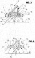
- FIG 4 shows a wiper blade 6a as a further embodiment, which differs from the wiper blade 6 in that in the case of the wiper blade 6a, the internal supporting elements 9 have been omitted and the wiping rubber 8a is constructed with a spoiler-like profile section 8.2 instead, which on the upper side facing away from the wiping lip 12 on both sides of the wiper blade adapter is covered by a shell-like, thin-walled spoiler element 25 respectively, which forms the outer surface of this wiper blade 6a at this position and is directly retained by two fastening sections 26 and 27 on the external peripheries of both spring rails 7.
- the respective spoiler element 25 is provided, at the fastening sections 26 and 27 respectively, with a reinforcing profile 28 surrounding the spring rail 7 involved on its external edge and extending over the entire longitudinal side of the spoiler element 25. Furthermore, the one-piece spoiler element 25 is designed in turn at its fastening sections 26 and 27 as a jet or injection strip with the injection or washing ducts 20 and 21 presenting the injection openings 22.
- the wiper blade 6a also presents a spoiler element 25 respectively on both sides of the wiper blade adapter 11, extending from the wiper blade adapter 11 to the end of the wiper blade opposite to the latter.
- FIG. 5 shows a wiper blade 6b as a further embodiment, essentially consisting of the wiping rubber 8b, the two spring rails 7 respectively engaging in a groove 13 of the wiping rubber 8b, of the internal, spoiler-like-shaped, shell-like supporting elements 29 and of the external spoiler elements 25, which are constructed in one piece with the U-shaped reinforcing profiles 28 and the injection or washing ducts 20 and 21 presenting the injection openings 22.
- the spoiler elements 25 provided on both sides of the wiper blade adapter 11 with their fastening sections 26 and 27 and with the reinforcing profiles 28 at this position on the external peripheries of the spring rails facing away from the wiping rubber 8b are directly retained surrounding these peripheries.
- the internal supporting elements 29 are constructed in one piece with U-shaped fastening sections 30, which surround the spring rails 7 at their internal peripheries in relation to the wiping rubber and to be more precise within the grooves 13 of the wiping rubber 8b partially receiving the spring rails 7.
- Figure 6 shows a wiper blade 6c as a further embodiment, which differs from the wiper blade 6a in that on the upper side of the spring rails 7 facing away from the wiping lip, a heating foil 31 is respectively provided for electrically heating the wiper blade 6c and particularly also the injection or washing ducts 20 and 21, which reaches into the corresponding groove 13 of the wiping rubber 8a and is surrounded by the reinforcing profiles 28 of the fastening sections 26 and 27 at the external peripheries of the spring rails 7 which form the jet or injection strips presenting the injection or washing ducts 20 and 21.
- FIG. 7 shows as a further embodiment a wiper blade 6a, which essentially differs from the wiper blade 6a in that although the respective thin-walled and shell-shaped spoiler element 32 covering the spoiler-like profile section 8.2 of the wiping rubber 8a is once again retained with the fastening sections 33 and 34 directly spanning the spring rails at their external peripheries, it only presents the injection or washing duct 21 on one longitudinal side of the wiper blade.
- This injection and washing duct 21 is provided in this case above the upper side of the right spring rail facing away from the wiping lip 12 in Figure 7 and to be more precise on the longitudinal side of the wiper blade on which the wiper blade has its greatest height owing to its spoiler-like upper side of the wiper blade.
- FIGs 8 and 9 once again show the wiper arm 1 together with a wiper blade fastened to this wiper arm 1, for example the wiper blade 35 in Figure 10 , which (wiper blade) is once again constructed as a flat wiper blade and accordingly consists essentially of the two flat, spring rails 7 manufactured from a sprung metallic material, for example spring steel and of the wiping rubber 8a manufactured from a profile made of elastic rubber material, which forms the wiping lip 12 in contact with the vehicle windscreen FS at least during wiping operation and is provided with grooves 13 into which the spring rails 7 reach with a part of their width, so that the wiping rubber 8a is received between the spring rails 7 with the section 8.1 of reduced width.
- a wiper blade fastened to this wiper arm 1 for example the wiper blade 35 in Figure 10
- the wiper blade 35 in Figure 10 which (wiper blade) is once again constructed as a flat wiper blade and accordingly consists essentially of the two flat, spring rails 7 manufactured from a sprung metallic material, for example
- the wiping rubber 8a is designed on the upper side facing away from the wiping lip 12 with the spoiler-like profile section 8.2.
- the wiper blade adapter 11 serving for fastening to the wiper arm 1 and to the adapter 5 at this position is once again provided and to be more precise spanning the two spring rails 7 at their external peripheries and also the wiper blade 35 overall on the upper side of the wiper blade.
- the wiper blade 35 with the cover caps 14 corresponding to the cover caps 36 is provided, which forms a visual conclusion and simultaneously hold together the elements of the wiper blade 35, i.e. the wiping rubber 8a and the spring rails 7.
- jet or injection strips 39 On both sides of the wiper blade adapter 11, two jet or injection strips 39, each respectively forming an injection duct 37 having a large number of injection openings 37.1 are provided.
- the jet or injection strips 39 are each constructed in one piece with a U-shaped fastening section 40, extending over the entire length of the respective jet or injection strip 39, by means of which the respective jet or injection strip 39 is retained on a spring rail 7 by pushing on to the periphery of the latter external in relation to the wiping rubber 8a.
- the fastening is of such a nature that the injection duct 37 is located above the upper side of the spring rail 7 in question facing away from the wiping lip and to be more precise within the corner area formed between the upper side of the spring rail 7 and the spoiler-like profile section 8.2 on the longitudinal side of the wiper blade on which the wiper blade 35 has its greatest height owing to the spoiler-like construction.
- the respective injection strip 39 is secured on the wiper blade 35 by means of several clips 41, manufactured from a suitable material, for example from a metallic material or plastic.
- Each clip 41 is constructed such that the latter, on one longitudinal side of the wiper blade, spans the injection strip 39 and the fastening section 40 with a U-shaped retaining section 42 and on the other longitudinal side of the wiper blade, spans the spring rail 7 at this position on the latter's external periphery by a U-shaped retaining section 43. Between the two retaining sections 42 and 43, each clip 41 is shaped according to the outer contour of the spoiler-like profile section 8.2.
- the injection or washing ducts 37 are closed in a suitable manner.
- the injection ducts 37 are connected to one another by means of the connecting piece 23 and also to the tube line 24 for supplying the washing and cleaning fluid, with the tube section 23.1 preferably being likewise equipped with injection openings 23.3.
- the connecting piece 23 is constructed as a T piece and to be more precise with a tube section 23.1 extending in the longitudinal direction of the wiper blade and connected at both ends to a tube section 23.1 with one injection or washing duct 37 respectively and with a tube section 23.2 extending away radially from the former tube section for connection of the tube line 24.
- connecting piece 23 is also of course conceivable, for example as a Y connection piece, i.e. in such a form that the tube section 23.2 projects away at an angle from the tube section 23.1 and to be more precise, adapted to the course that the tube line 24 presents at its end connected to the respective distribution and connecting piece 23
- Figure 11 shows a wiper blade 35a as a further embodiment, which essentially differs from the wiper blade 35 only in that the jet or injection strips 39 are fastened on the one longitudinal side of the wiper blade and on the spring rail 7 at this position in such a manner that the respective injection or washing duct 37 is located underneath the underside of the spring rail 7 facing towards the wiping lip 12.
- Clips 41 a serve in order to secure the two injection strips 39 extending once again between the wiper blade adapter 11 and one end of the wiper blade 35a respectively, which (clips) secure by means of a clipping or retaining section 42 the respective injection strip 39 on one longitudinal side of the wiper blade and span by means of the clipping or retaining section 43 the spring rail 7 on the other longitudinal side of the wiper blade, thereby securing the injection strips 39 on the wiper blade 35a.
- Figure 12 shows a wiper blade 35b as a further embodiment, which essentially differs from the wiper blade 35 in that instead of the injection strips 39, injection strips 44 are provided that once again form an injection duct 37 with a large number of jet or injection openings 38 and are fastened by a U-shaped fastening section 45 to the external periphery of the spring rail on the longitudinal side of the wiper blade on which the wiper blade, owing to a spoiler-like construction, has the greatest height.
- the injection strips 44 are constructed in such a way in this case that the respective injection or washing duct 37 is arranged at the same level or approximately the same level as the adjacent spring rail 7 and is therefore located to the side of the spring rail 7.
- the injection strips 44 are retained on the wiper blade 35b by several clips 41 b spanning the injection strips on one longitudinal side of the wiper blade and the spring rail 37 on the other longitudinal side of the wiper.
- FIG 13 shows a wiper blade 35 which essential differs from the wiper blade 35b in that the wiping rubber 8 does not present the spoiler-like section 8.2 and a spoiler profile 46 constructed as a hollow profile is fastened on the upper side of the wiper blade on both sides of the wiper blade adapter 11 and to be more precise in such a manner that this spoiler profile is constructed in one piece with two U-shaped fastening sections 47 and 48, which in the assembled state span the external peripheries of the spring rails 7.
- the jet or injection strip 44 with an adapted fastening section 45 is once again provided, which spans the fastening section 48 of the spoiler profile 46.
- the two injection strips 44 are secured on the wiper blade 35c by several adapted retaining clips 41 c, with the retaining clips 41c also serving to secure the respective spoiler profile 46.
- Figure 14 shows a wiper blade 35d as a further embodiment, which essentially only differs from the wiper blade 35c in that instead of the jet or injection strip 44, a jet or injection strip 39 with an adapted fastening section 40 spanning the fastening section 48 is provided and for securing the injection strips 39, adapted clips 41d spanning the upper side of the wiper blade are provided.
- FIG 15 finally shows a wiper blade 35e, which essentially only differs from the wiper blade 35b in that one both longitudinal sides of the wiper blade respectively, jet or injection strips 44 are provided that are retained at this position by means of their fastening sections 45 on the external periphery of a spring rail 7 and are secured by several clips 41 e, which respectively span the injection strips 44 with their U-shaped clip ends and secure these injection strips on the spring rails 7.
- the wiper blade 35e therefore presents an injection duct 37 respectively on both longitudinal sides of the wiper blade having a large number of injection openings 38.
- the injection ducts 37 on each longitudinal side are connected to one another by means of a connecting piece or connector 23 and to a tube line 24 for supplying the washing and cleaning fluid.
- these spring rails may also be the component of a spring rail element, of fork-like design for example and to be more precise with two fork arms formed of one spring rail respectively, connected to each other at one end of the spring rail element.
Abstract
Description
- The invention refers to a flat wiper blade according to the generic term in
patent claim 1 or 8 and in this case specifically to a flat wiper blade having at least one injection or washing duct on at least one longitudinal side of the wiper blade, presenting a large number of jet or injection openings for application of a washing and cleaning fluid to a vehicle windscreen. - Flat wiper blades are known in various different embodiments. Flat wiper blades are also particularly known (
DE 103 35 394 A1 ) having two flat spring rails spaced apart from each other extending in the longitudinal direction of the wiper blade and a wiping rubber forming the wiping lip, wherein the spring rails are respectively received over part of their width in grooves on the longitudinal sides of the wiping rubber and therefore receive the wiping rubber between them in a wiping rubber section remaining between the grooves. A profile constructed as a spoiler (spoiler profile) is fixed to the external peripheries of the spring rails facing away from the wiping rubber. - Flat wiper blades are furthermore known (
DE 10 2006 013 900 A1 ) having a spoiler-like-shaped wiper blade body, formed of a length of a solid plastic profile, which, on the external peripheries of two spring rails facing away from the wiping rubber, is retained spanning these peripheries. The wiper blade body is provided on both longitudinal sides of the wiper blade respectively with injection and washing ducts presenting a large number of jet or injection openings. Disadvantageous among other aspects are the high mass and impaired flexibility of the wiper blade determined by the solid, spoiler-like wiper blade body. - Wiper blades are furthermore known (
DE 10 2007 030 169 A1 ) having a single flat spring rail surrounded by the wiping rubber and with a spoiler profile forming the upper side of the wiper blade, which (spoiler profile) on the profile section of the wiping rubber surrounding the spring rail, is retained positively spanning the wiping rubber in the manner of a slide on the upper side of the wiper blade. The flat wiper blade presents on at least one longitudinal side of the wiper blade an injection strip manufactured in one piece with the spoiler profile with an injection and washing duct having a large number of jets or injection openings. - Flat wiper blades are furthermore known (
EP 1 178 807 B1 ) with two spring rails and a wiping rubber received between the spring rails, which forms the wiping lip on the underside of the wiper blade and is constructed shaped as a spoiler, i.e. with a spoiler-like profile section, on the upper side of the wiper blade. A jet or injection strip is fixed respectively to the projecting spring rails with an injection or washing duct having a large number of jets or injection openings and to be more precise with a fastening section spanning the external periphery of the spring rail in question in the manner of a clip. In order to secure the respective injection or jet strips, openings are provided in the projecting spring rails, in which projections on the fastening sections of the jet strips engage and lock. Disadvantageous in this case is elaborate assembly owing to a large number of individual components and particularly also the fact that differences in colour in the case of the large number of the individual parts cannot be avoided and therefore the uniform appearance also sought for the colouring of the wiper blade cannot be achieved. - Flat wiper blades are furthermore known (EP 1 918 167*), presenting an injection or washing duct having a large number of jet or injection openings on a longitudinal side of the wiper blade, with this injection and washing duct being formed of a tube, which is retained by several clip-like fixing elements spaced apart from one another in the longitudinal direction of the wiper blade and spanning the upper side of the wiper blade. Disadvantageous in this case is particularly the relatively large amount of expenditure in terms of assembly and the associated high assembly costs due to a large number of individual components.
- The purpose of the invention is to demonstrate a flat wiper blade provided on at least one longitudinal side of the wiper blade with an injection or washing duct having a large number of jet or injection openings and presenting improved visual and/or mechanical properties with simplified assembly.
- In order to solve this problem, a flat wiper blade according to
patent claim 1 or 8 is developed. - According to one aspect of the invention, at least one spoiler element is provided on the upper side of the wiper blade, which is constructed in one piece with at least one jet or injection strip extending in the assembled state along a longitudinal side of the wiper blade. The particularity of the wiper blade in this case lies in the fact that the spoiler element is designed in the manner of a shell and to be more precise in such a manner that for its fastening to both longitudinal sides of the wiper blade, it directly or however indirectly spans the external peripheries of the spring rails. As a result of the shell-shaped embodiment of the spoiler element, a construction of the wiper blade with reduced mass and with a flexibility unimpaired by the spoiler element is possible.
- The shell-like spoiler element possesses a wall thickness that is for example of the order of magnitude of the spring rail thickness, i.e. of the order of magnitude of the thickness of the flat material used to manufacture the spring rails; preferably, the wall thickness of the shell-like spoiler element is at the most identical to or however less than the spring rail thickness.
- The possibility fundamentally exists of supporting the spoiler element internally and to be more precise for example by means of an internal supporting profile or supporting element extending over the entire length of the spoiler element, or however also only partially by means of supporting elements spaced apart from one another in the longitudinal direction of the wiper blade. The supporting profile is then for example an independent, hollow profile or hollow chamber profile externally retained on the spring rails. The shell-like spoiler element is then retained spanning this supporting profile in the area of the spring rails indirectly on this supporting profile. The supporting profile may also be formed of a spoiler-like profile section of the wiping rubber itself.
- According to another aspect of the invention, a jet or injection strip is fixed to at least one longitudinal side of the wiper blade, presenting at least one injection or washing duct with a large number of jet or injection openings for application of the washing and cleaning fluid.
- The jet or injection strip is constructed in one piece with a fastening section, by means of which it is retained on the wiper blade in the area of the external edge of a spring rail and preferably extending over the entire or essentially the entire length of the jet or injection strip. The at least one jet or injection strip is secured by several clip-like or clasp-like securing elements spaced apart from one another in the longitudinal direction of the wiper blade, which span the at least one jet or injection strip in addition to the wiper blade on its upper side and are retained positively and preferably by locking on the wiper blade in the area of the spring rails. The clip-like or clasp-like securing elements are not an integral part of the at least one jet or injection strip, but independent, thin-walled elements. If the wiper blade is constructed as a spoiler at least in subareas on the upper side of the wiper blade, the clip-like or clasp-like securing elements at this position are adapted in shape to the spoiler profile.
- Further developments, advantages and application possibilities of the invention are also apparent from the following description of examples of embodiment and from the figures. In this case, all the characteristics described and/or illustrated are in themselves or in any desired combination fundamentally a subject of the invention, regardless of their summary in the claims or their backward relation. The contents of the claims are also made an integral part of the description.
- The invention is described below in further detail in examples of embodiment based on the figures:
- Fig. 1
- shows a perspective representation of a wiper arm together with a flat wiper blade fixed to this wiper arm, which is constructed as an aqua wiper blade, with a spoiler and at least one injection or washing duct on at least one longitudinal side of the wiper blade;
- Fig. 2
- shows a lateral view of the wiper blade in
Figure 1 together with the wiper arm end bearing this wiper blade; - Fig. 3 - 7
- shows simplified representations of a section through the wiper blade in
Figures 1 and2 respectively with different embodiments of the invention; - Fig. 8
- shows a perspective representation of a wiper arm together with a wiper blade fixed to one end of the wiper arm in a further general embodiment of the invention;
- Fig. 9
- shows a side view of the wiper blade in
Figure 7 , together with the wiper arm end bearing the wiper blade; - Fig. 10 -
- 15 show simplified representations respectively of a section through the wiper blade in
Figures 8 and9 with different embodiments of the invention; - In
Figures 1 - 7 , 1 is the wiper arm of a windscreen wiper module for vehicle windscreens FS, particularly vehicle front windscreens. The wiper arm 1 consists in the well known manner of a pivot section 2, by means of which the wiper arm 1 can be mounted on a wiper shaft not illustrated, in addition to a wiper arm element 4 (wiper rod) articulated on the pivot section 2 by means of awiper arm link 3, which (wiper arm element) is provided on its end distant from the pivot section 2 with anadapter 5 on the wiper arm side for detachable flexible fixing of a wiper blade, for example thewiper blade 6 inFigure 3 . - The
wiper blade 6 is constructed as a flat wiper blade and comprises for this purpose at least twoflat spring rails 7, manufactured from a sprung metallic material, for example spring steel, awiping rubber 8, two spoiler-like-shaped, strip-like supportingelements 9, two shell-like spoiler elements 10 forming the upper side of thewiper blade 6, in addition to awiper blade adapter 11 for detachable flexible connection to theadapter 5. - The two
spring rails 7 and thewiping rubber 8, which forms thewiping lip 12 in contact with the vehicle windscreen FS at least during wiping operation, respectively extend over the entire length of thewiper blade 6, with a part of the width of eachspring rail 7 reaching into agroove 13 provided on one longitudinal side of thewiping rubber 8 and to be more precise in such a manner that thespring rails 7 receive thewiping rubber 8 between each other in the area of a section 8.1 of reduced width. - The
adapter 11 on the wiper blade side is fastened in the middle or approximately in the middle of thewiper blade 6 to the peripheries of thespring rails 7 projecting laterally from thewiping rubber 8 and to be more precise surrounding thespring rails 7 at these peripheries and spanning in the manner of a slide thewiper blade 6 and the part of thewiper blade 6 formed by thespring rails 7 and thewiping rubber 8 on the upper side of the wiper blade facing away from thewiping lip 12. The supportingelements 9, spoiler-like-shaped and manufactured for example from plastic as a hollow profile and the shell-like spoiler elements 10 likewise manufactured from plastic and covering a supporting element respectively in the assembled state each extend starting from a front side of theadapter 11 on the wiper blade side to the end of thewiper blade 6 opposite this front side.Cover caps 14 formed of plastic for example are provided at both ends of thewiper blade 6, which not only serve for a visually appealing conclusion to thewiper blade 6 at the wiper blade ends, but simultaneously also hold together the elements of thewiper blade 6 at this position, i.e. the twospring rails 7, thewiping rubber 8, the supportingelement 9 and thespoiler element 10. - Each supporting
element 9 is in one piece, consisting of a spoiler-likehollow profile 15 with a reinforcing ridge and is constructed with twoU-shaped fastening sections 16 extending respectively along a longitudinal side of the supportingelement 9, which for fixing of the respective supportingelement 9, positively span in the assembled state the twospring rails 7 at their peripheries external in relation to thewiping rubber 8. Thefastening sections 16 consist in this case of a plastic for example that presents a greater hardness in comparison to that used for thehollow profile 15. - Each supporting
element 9 is covered by one of thespoiler elements 10, which is constructed of a suitable plastic in a shell-like manner following the spoiler-like outer contour of the supportingelement 9 and forms the outer surface of the upper side of thewiper blade 6 designed as a spoiler. The shell-like spoiler element 10 respectively possesses a wall thickness equal to or less than the thickness of thespring rails 7. For fastening, thespoiler element 10 is constructed in one piece with twofastening sections 17 und 18, which in the assembled state of thespoiler element 10, span the supportingprofile 9 in the area of its fastening section externally in a U-shape. In the area of thefastening sections spoiler element 10 is provided for example with a U-shaped or C-shaped profile section 19, which spans the supportingelement 9 and reinforces therespective fastening section - The particularity of the
wiper blade 6 lies in the fact that eachspoiler element 10 is constructed in the area of itsfastening sections washing duct respective spoiler element 10 and respectively presents a large number of jet orinjection openings 22 for application of a washing and cleaning fluid (water with cleaning and/or antifreeze additives if necessary) to the vehicle windscreen FS. - At each wiper blade end, the injection and
washing ducts cover cap 14 at this position. In the middle of the wiper blade, i.e. in the area of theadapter 11 on the wiper blade side, the injection orwashing ducts piece 23 formed of a T tube and also with atube line 24 for supplying the washing and cleaning fluid under pressure. The connection is for instance such that theinjection ducts 20 on one longitudinal side of thewiper blade 6 are connected with atube line 23 and theinjection ducts 21 on the other longitudinal side of thewiper blade 6 are connected with aseparate tube line 23, so that application of the washing and cleaning fluid independently from the direction of movement of thewiper blade 6 is possible on wiping, for example in such a manner that application of the washing and cleaning fluid to the vehicle windscreen FS occurs in each case ahead of thewiper blade 6. - In the embodiment presented, the connecting
pieces 23 are respectively constructed as T pieces and to be more precise with a tube section 23.1 extending in the longitudinal direction of the wiper blade and connected at both ends with one injection orwashing duct tube line 24. Other embodiments of the connectingpiece 23 are also of course conceivable, for example as a Y connector, i.e. in such a form that the tube section 23.2 projects away at an angle from the tube section 23.1 and to be more precise, adapted to the course that thetube line 24 presents at its end connected to the respective distribution and connectingpiece 23. - It is also preferable to provide the connecting
piece 23 and the latter's tube section 23.1 with a large number of injection and jet openings 23.3, so that continuous emergence of the spray or washing fluid on each longitudinal side of the wiper blade is possible over the entire length of the wiper blade. -
Figure 4 shows awiper blade 6a as a further embodiment, which differs from thewiper blade 6 in that in the case of thewiper blade 6a, the internal supportingelements 9 have been omitted and the wipingrubber 8a is constructed with a spoiler-like profile section 8.2 instead, which on the upper side facing away from the wipinglip 12 on both sides of the wiper blade adapter is covered by a shell-like, thin-walled spoiler element 25 respectively, which forms the outer surface of thiswiper blade 6a at this position and is directly retained by twofastening sections respective spoiler element 25 is provided, at thefastening sections profile 28 surrounding thespring rail 7 involved on its external edge and extending over the entire longitudinal side of thespoiler element 25. Furthermore, the one-piece spoiler element 25 is designed in turn at itsfastening sections washing ducts injection openings 22. - Analogously to the
wiper blade 6, thewiper blade 6a also presents aspoiler element 25 respectively on both sides of thewiper blade adapter 11, extending from thewiper blade adapter 11 to the end of the wiper blade opposite to the latter. -
Figure 5 shows a wiper blade 6b as a further embodiment, essentially consisting of the wipingrubber 8b, the twospring rails 7 respectively engaging in agroove 13 of the wipingrubber 8b, of the internal, spoiler-like-shaped, shell-like supportingelements 29 and of theexternal spoiler elements 25, which are constructed in one piece with the U-shaped reinforcingprofiles 28 and the injection orwashing ducts injection openings 22. As in the case of thewiper blade 6a, thespoiler elements 25 provided on both sides of thewiper blade adapter 11 with theirfastening sections profiles 28 at this position on the external peripheries of the spring rails facing away from the wipingrubber 8b are directly retained surrounding these peripheries. The internal supportingelements 29 are constructed in one piece withU-shaped fastening sections 30, which surround the spring rails 7 at their internal peripheries in relation to the wiping rubber and to be more precise within thegrooves 13 of the wipingrubber 8b partially receiving the spring rails 7. -
Figure 6 shows awiper blade 6c as a further embodiment, which differs from thewiper blade 6a in that on the upper side of the spring rails 7 facing away from the wiping lip, aheating foil 31 is respectively provided for electrically heating thewiper blade 6c and particularly also the injection orwashing ducts groove 13 of the wipingrubber 8a and is surrounded by the reinforcingprofiles 28 of thefastening sections washing ducts -
Figure 7 shows as a further embodiment awiper blade 6a, which essentially differs from thewiper blade 6a in that although the respective thin-walled and shell-shapedspoiler element 32 covering the spoiler-like profile section 8.2 of the wipingrubber 8a is once again retained with thefastening sections duct 21 on one longitudinal side of the wiper blade. This injection and washingduct 21 is provided in this case above the upper side of the right spring rail facing away from the wipinglip 12 inFigure 7 and to be more precise on the longitudinal side of the wiper blade on which the wiper blade has its greatest height owing to its spoiler-like upper side of the wiper blade. -
Figures 8 and9 once again show the wiper arm 1 together with a wiper blade fastened to this wiper arm 1, for example thewiper blade 35 inFigure 10 , which (wiper blade) is once again constructed as a flat wiper blade and accordingly consists essentially of the two flat, spring rails 7 manufactured from a sprung metallic material, for example spring steel and of the wipingrubber 8a manufactured from a profile made of elastic rubber material, which forms the wipinglip 12 in contact with the vehicle windscreen FS at least during wiping operation and is provided withgrooves 13 into which the spring rails 7 reach with a part of their width, so that the wipingrubber 8a is received between the spring rails 7 with the section 8.1 of reduced width. The wipingrubber 8a is designed on the upper side facing away from the wipinglip 12 with the spoiler-like profile section 8.2. In the middle, or approximately in the middle of thewiper blade 35, thewiper blade adapter 11 serving for fastening to the wiper arm 1 and to theadapter 5 at this position is once again provided and to be more precise spanning the twospring rails 7 at their external peripheries and also thewiper blade 35 overall on the upper side of the wiper blade. At both ends, thewiper blade 35 with the cover caps 14 corresponding to the cover caps 36 is provided, which forms a visual conclusion and simultaneously hold together the elements of thewiper blade 35, i.e. the wipingrubber 8a and the spring rails 7. - On both sides of the
wiper blade adapter 11, two jet or injection strips 39, each respectively forming aninjection duct 37 having a large number of injection openings 37.1 are provided. The jet or injection strips 39 are each constructed in one piece with aU-shaped fastening section 40, extending over the entire length of the respective jet orinjection strip 39, by means of which the respective jet orinjection strip 39 is retained on aspring rail 7 by pushing on to the periphery of the latter external in relation to the wipingrubber 8a. The fastening is of such a nature that theinjection duct 37 is located above the upper side of thespring rail 7 in question facing away from the wiping lip and to be more precise within the corner area formed between the upper side of thespring rail 7 and the spoiler-like profile section 8.2 on the longitudinal side of the wiper blade on which thewiper blade 35 has its greatest height owing to the spoiler-like construction. Therespective injection strip 39 is secured on thewiper blade 35 by means ofseveral clips 41, manufactured from a suitable material, for example from a metallic material or plastic. Eachclip 41 is constructed such that the latter, on one longitudinal side of the wiper blade, spans theinjection strip 39 and thefastening section 40 with aU-shaped retaining section 42 and on the other longitudinal side of the wiper blade, spans thespring rail 7 at this position on the latter's external periphery by aU-shaped retaining section 43. Between the two retainingsections clip 41 is shaped according to the outer contour of the spoiler-like profile section 8.2. - On both wiper blade ends, the injection or
washing ducts 37 are closed in a suitable manner. In the centre of thewiper blade 35, i.e. in the area of thewiper blade adapter 11, theinjection ducts 37 are connected to one another by means of the connectingpiece 23 and also to thetube line 24 for supplying the washing and cleaning fluid, with the tube section 23.1 preferably being likewise equipped with injection openings 23.3. In the embodiment presented, the connectingpiece 23 is constructed as a T piece and to be more precise with a tube section 23.1 extending in the longitudinal direction of the wiper blade and connected at both ends to a tube section 23.1 with one injection or washingduct 37 respectively and with a tube section 23.2 extending away radially from the former tube section for connection of thetube line 24. Other embodiments of the connectingpiece 23 are also of course conceivable, for example as a Y connection piece, i.e. in such a form that the tube section 23.2 projects away at an angle from the tube section 23.1 and to be more precise, adapted to the course that thetube line 24 presents at its end connected to the respective distribution and connectingpiece 23 -
Figure 11 shows awiper blade 35a as a further embodiment, which essentially differs from thewiper blade 35 only in that the jet or injection strips 39 are fastened on the one longitudinal side of the wiper blade and on thespring rail 7 at this position in such a manner that the respective injection or washingduct 37 is located underneath the underside of thespring rail 7 facing towards the wipinglip 12.Clips 41 a serve in order to secure the twoinjection strips 39 extending once again between thewiper blade adapter 11 and one end of thewiper blade 35a respectively, which (clips) secure by means of a clipping or retainingsection 42 therespective injection strip 39 on one longitudinal side of the wiper blade and span by means of the clipping or retainingsection 43 thespring rail 7 on the other longitudinal side of the wiper blade, thereby securing the injection strips 39 on thewiper blade 35a. -
Figure 12 shows awiper blade 35b as a further embodiment, which essentially differs from thewiper blade 35 in that instead of the injection strips 39, injection strips 44 are provided that once again form aninjection duct 37 with a large number of jet orinjection openings 38 and are fastened by aU-shaped fastening section 45 to the external periphery of the spring rail on the longitudinal side of the wiper blade on which the wiper blade, owing to a spoiler-like construction, has the greatest height. The injection strips 44 are constructed in such a way in this case that the respective injection or washingduct 37 is arranged at the same level or approximately the same level as theadjacent spring rail 7 and is therefore located to the side of thespring rail 7. - The injection strips 44 are retained on the
wiper blade 35b byseveral clips 41 b spanning the injection strips on one longitudinal side of the wiper blade and thespring rail 37 on the other longitudinal side of the wiper. -
Figure 13 shows awiper blade 35 which essential differs from thewiper blade 35b in that the wipingrubber 8 does not present the spoiler-like section 8.2 and aspoiler profile 46 constructed as a hollow profile is fastened on the upper side of the wiper blade on both sides of thewiper blade adapter 11 and to be more precise in such a manner that this spoiler profile is constructed in one piece with twoU-shaped fastening sections - On one longitudinal side of the wiper blade and to be more precise on the longitudinal side of the wiper blade with the greatest height, the jet or
injection strip 44 with an adaptedfastening section 45 is once again provided, which spans thefastening section 48 of thespoiler profile 46. The twoinjection strips 44 are secured on the wiper blade 35c by several adapted retainingclips 41 c, with the retainingclips 41c also serving to secure therespective spoiler profile 46. -
Figure 14 shows awiper blade 35d as a further embodiment, which essentially only differs from the wiper blade 35c in that instead of the jet orinjection strip 44, a jet orinjection strip 39 with an adaptedfastening section 40 spanning thefastening section 48 is provided and for securing the injection strips 39, adaptedclips 41d spanning the upper side of the wiper blade are provided. -
Figure 15 finally shows awiper blade 35e, which essentially only differs from thewiper blade 35b in that one both longitudinal sides of the wiper blade respectively, jet or injection strips 44 are provided that are retained at this position by means of theirfastening sections 45 on the external periphery of aspring rail 7 and are secured byseveral clips 41 e, which respectively span the injection strips 44 with their U-shaped clip ends and secure these injection strips on the spring rails 7. Thewiper blade 35e therefore presents aninjection duct 37 respectively on both longitudinal sides of the wiper blade having a large number ofinjection openings 38. Theinjection ducts 37 on each longitudinal side are connected to one another by means of a connecting piece orconnector 23 and to atube line 24 for supplying the washing and cleaning fluid. - The invention has been described above based on examples of embodiment. It is understood that modifications and variations are possible without departing as a result from the concept on which the invention is based.
- It has been assumed above that the flat wiper blade presents two
separate spring rails 7 respectively. Fundamentally, these spring rails may also be the component of a spring rail element, of fork-like design for example and to be more precise with two fork arms formed of one spring rail respectively, connected to each other at one end of the spring rail element. The possibility also exists of designing the strip-like spring rail element with an elongated hole, so that onespring rail 7 respectively is formed on both sides of this elongated hole. -
- 1
- wiper arm
- 2
- pivot section
- 3
- wiper arm link
- 4
- wiper arm element or wiper rod
- 5
- adapter on wiper arm side
- 6, 6a - 6d
- wiper blade
- 7
- spring rail
- 8
- wiping rubber
- 8.1, 8.2
- wiping rubber section
- 9
- internal supporting element
- 10
- spoiler element
- 11
- wiper blade adapter
- 12
- wiping lip
- 13
- groove for
spring rail 7 - 14
- cover cap
- 15
- hollow profile
- 16, 17, 18
- fastening section
- 19
- strip-like reinforcing profile
- 20, 21
- injection or washing duct
- 22
- injection opening
- 23
- distribution or connecting piece
- 23.1, 23.2
- tube section of the connecting
piece 23 - 23.3
- injection opening in the tube section 23.1
- 24
- tube line
- 25
- spoiler element
- 26, 27
- fastening section
- 28
- strip-like reinforcing profile
- 29
- supporting element or profile
- 30
- fastening section
- 31
- heating film
- 32
- spoiler element
- 33, 34
- fastening section
- 35, 35a - 35e
- flat wiper blade
- 36
- end cap
- 37
- injection duct
- 37.1
- injection openings
- 38
- injection opening
- 39
- injection strip
- 40
- U-shaped fastening section
- 41, 41a-41e
- fastening clip or clasp
- 42, 43
- clip section
- 44
- injection strip
- 45
- fastening section
- 46
- spoiler profile
- 47, 48
- U-shaped fastening section of the
spoiler profile 46
Claims (8)
- Flat wiper blade, which on an upper side of the wiper blade is designed in the manner of a spoiler over at least a sub length, having at least one wiping rubber (8, 8a, 8b) forming a wiping lip (12), with two spring rails (12), extending in the longitudinal direction of the wiper blade, spaced apart from one another and receiving the wiping rubber (8, 8a, 8b) in the area of a subsection (8.1) between them and with at least one jet or injection strip (17, 18; 26, 27) provided on at least one longitudinal side of the wiper blade, which forms the at least one injection or washing duct (20, 21) presenting a large number of injection openings (22) and is fastened in the area of a peripheral edge of one of the spring rails (7) laterally projecting over the wiping rubber (8, 8a, 8b), characterised in that the at least one jet or injection strip (17, 18; 26, 27) is designed in one piece with a shell-like spoiler element (10, 25) forming the spoiler-like outer surface of the wiper blade (6, 6a - 6d).
- Flat wiper blade according to claim 1, characterised in that the at least one jet or injection strip forms a fastening section (17, 18; 26, 27), by means of which the spoiler element (10, 25) is retained on the wiper blade (6, 6a - 6d).
- Flat wiper blade according to claim 1 or 2, characterised by at least one internal, preferably spoiler-like-shaped supporting element (9, 8.2) supporting the spoiler element (10, 25) at least in subareas.
- Flat wiper blade according to claim 3, characterised in that the internal supporting element (9) is formed of a spoiler-like-shaped hollow profile, which with fastening sections (16) on the peripheries of the spring rails (7) external in relation to the wiping rubber (8, 8a, 8b) is retained on the spring rails and to be more precise preferably spanning these peripheries and that the spoiler element (10) spans with fastening sections (17, 18) the spoiler-like supporting element on the longitudinal sides of the wiper blade or on its fastening sections (16) at this position.
- Flat wiper blade according to one of the above claims, characterised in that the internal supporting element is formed of a spoiler-like-shaped profile section (8.2) of the wiping rubber (8, 8a, 8b) and that the spoiler element (25) spans the spring rails (7) with fastening sections (26, 27) on external peripheries in a U-shape or in the manner of a clip, with at least one fastening section (26, 27) being constructed as a jet or injection strip with at least one injection or washing duct (20, 21) and a large number of injection openings (22) or being designed in one piece with a jet or injection strip presenting the at least one injection or washing duct (20, 21).
- Flat wiper blade according to one of the above claims, characterised in that the at least one injection or washing duct (20, 21) is arranged above or underneath the adjacent spring rail (7) or at the same or essentially the same level.
- Flat wiper blade according to one of the above claims, characterised in that on both sides of a wiper blade adapter (11) serving to fasten the wiper blade (6, 6a - 6d) on a wiper arm (1), at least one spoiler element (10, 25) having at least one jet or injection strip (17, 18; 26, 27) is provided on at least one longitudinal side of the wiper blade and that the injection or washing ducts (21, 22) on the longitudinal side of the wiper blade are connected to one another by means of a distribution or connecting piece (23), wherein the connecting piece (23) presents at least one connection (23.2) for connecting to a line (24) for supplying a washing and cleaning fluid in addition to preferably additional injection openings (23.3) for application of the cleaning and washing fluid to a vehicle windscreen (FS).
- Flat wiper blade according to one of the above claims, characterised by at least one electrical heating element formed for example of a heating film (31) on the at least one jet or injection strip (17, 18; 26, 27, 39, 44) or on the fastening section of the spoiler element (10, 25) forming this jet or injection strip or on the fixing element (40, 45) of the jet or injection strip.
Applications Claiming Priority (3)
| Application Number | Priority Date | Filing Date | Title |
|---|---|---|---|
| DE102009017990.9A DE102009017990B4 (en) | 2009-04-21 | 2009-04-21 | flat wiper blade |
| PCT/EP2010/002269 WO2010121729A2 (en) | 2009-04-21 | 2010-04-14 | Flat wiper blade |
| EP10730699.5A EP2421730B1 (en) | 2009-04-21 | 2010-04-14 | Flat wiper blade |
Related Parent Applications (2)
| Application Number | Title | Priority Date | Filing Date |
|---|---|---|---|
| EP10730699.5A Division-Into EP2421730B1 (en) | 2009-04-21 | 2010-04-14 | Flat wiper blade |
| EP10730699.5A Division EP2421730B1 (en) | 2009-04-21 | 2010-04-14 | Flat wiper blade |
Publications (2)
| Publication Number | Publication Date |
|---|---|
| EP3081443A1 true EP3081443A1 (en) | 2016-10-19 |
| EP3081443B1 EP3081443B1 (en) | 2019-12-18 |
Family
ID=42667411
Family Applications (2)
| Application Number | Title | Priority Date | Filing Date |
|---|---|---|---|
| EP16172013.1A Active EP3081443B1 (en) | 2009-04-21 | 2010-04-14 | Flat wiper blade |
| EP10730699.5A Active EP2421730B1 (en) | 2009-04-21 | 2010-04-14 | Flat wiper blade |
Family Applications After (1)
| Application Number | Title | Priority Date | Filing Date |
|---|---|---|---|
| EP10730699.5A Active EP2421730B1 (en) | 2009-04-21 | 2010-04-14 | Flat wiper blade |
Country Status (6)
| Country | Link |
|---|---|
| US (2) | US9440621B2 (en) |
| EP (2) | EP3081443B1 (en) |
| CN (1) | CN102414061B (en) |
| DE (1) | DE102009017990B4 (en) |
| PL (1) | PL2421730T3 (en) |
| WO (1) | WO2010121729A2 (en) |
Families Citing this family (40)
| Publication number | Priority date | Publication date | Assignee | Title |
|---|---|---|---|---|
| ES2865026T3 (en) * | 2010-04-23 | 2021-10-14 | Steam Tech Llc | Surface wiper system |
| DE102010052309A1 (en) * | 2010-11-16 | 2012-05-16 | Daimler Ag | Connecting element for attaching a wiper blade to a wiper arm of a windshield wiper system of a vehicle and Wischarmanordnung |
| DE102010056462A1 (en) * | 2010-12-30 | 2012-07-05 | Valeo Systèmes d'Essuyage | Wiper blade for cleaning windows of motor vehicles |
| DE102011012534A1 (en) * | 2011-02-26 | 2012-08-30 | GM Global Technology Operations LLC (n. d. Gesetzen des Staates Delaware) | Windscreen wiper and washing device for motor vehicle, comprises wiper arm movable in two opposite directions, at which flexible wiper lip and two fluid-conducting pipes impinged with washing fluid are arranged |
| FR2973758B1 (en) * | 2011-04-06 | 2013-05-17 | Valeo Systemes Dessuyage | ASSEMBLY OF A TIP AND A DEVICE FOR SPRAYING A LIQUID, WIPER BLADE COMPRISING SUCH AN ASSEMBLY, METHOD FOR MOUNTING A DEVICE FOR PROJECTING A LIQUID ON A TIP |
| FR2973759B1 (en) * | 2011-04-06 | 2016-10-21 | Valeo Systemes Dessuyage | LIQUID SPREADING DEVICE FOR WIPING BROOM |
| FR2975064B1 (en) | 2011-05-13 | 2013-05-17 | Valeo Systemes Dessuyage | LIQUID SPREADING DEVICE FOR WIPING BROOM |
| DE102011054066B4 (en) | 2011-09-29 | 2023-07-06 | Valeo Systèmes d'Essuyage | Wiper blade for cleaning vehicle windows |
| DE102011054065B4 (en) | 2011-09-29 | 2023-05-11 | Valeo Systèmes d'Essuyage | Wiper blade for a wiping device of a motor vehicle |
| DE102011054123A1 (en) * | 2011-09-30 | 2013-04-04 | Valeo Wischersysteme Gmbh | Wiper blade for cleaning vehicle windows |
| CN103958297B (en) * | 2011-12-02 | 2017-05-03 | 株式会社美姿把 | wiper blade |
| DE102011055962A1 (en) * | 2011-12-02 | 2013-06-06 | Valeo Systèmes d'Essuyage | Wiper device for cleaning a vehicle window |
| FR2994149B1 (en) * | 2012-08-02 | 2015-07-03 | Valeo Systemes Dessuyage | DEVICE FOR CONNECTION BETWEEN A WIPER ARM AND A WIPER, COMPRISING A DONE UP AREA TO RECEIVE A PLURALITY OF PROJECTION ORIFICES |
| CN103661280A (en) * | 2012-09-07 | 2014-03-26 | 张永波 | Protection type automobile wiper |
| KR101417490B1 (en) * | 2012-12-18 | 2014-07-08 | 현대자동차주식회사 | Apparatus for supplying washer liquid of vehicle |
| CN103121438B (en) * | 2013-01-31 | 2015-07-08 | 吉林大学 | Wetting type water spray windscreen wiper |
| FR3003220B1 (en) * | 2013-03-18 | 2015-03-20 | Coutier Moulage Gen Ind | WIPER BLADE WITH EJECTION ORIFICES AND MASK PIPE |
| US9248808B2 (en) | 2013-04-24 | 2016-02-02 | Trico Products Corporation | Heated wiper assembly |
| FR3006973B1 (en) * | 2013-06-14 | 2015-07-03 | Valeo Systemes Dessuyage | WIPING SYSTEM FOR PROJECTING A CLEANING AND / OR DEFROSTING FLUID AT A WIPER BLADE |
| FR3007361B1 (en) * | 2013-06-19 | 2017-03-03 | Valeo Systemes Dessuyage | WIPER BLADE |
| FR3007362B1 (en) * | 2013-06-19 | 2017-03-03 | Valeo Systemes Dessuyage | WIPER BLADE |
| WO2015069891A1 (en) | 2013-11-06 | 2015-05-14 | Federal-Mogul Motorparts Corporation | Rear windscreen wiper device |
| EP3065979A1 (en) * | 2013-11-06 | 2016-09-14 | Federal-Mogul Motorparts Corporation | Windscreen wiper device |
| FR3013287B1 (en) * | 2013-11-19 | 2017-07-14 | Valeo Systemes Dessuyage | VEHICLE GLASS WIPER SYSTEM HAVING A HEAT INDICATOR |
| CN103693019A (en) * | 2014-01-09 | 2014-04-02 | 任强 | Side-blown synchronous scrubbing windscreen wiper reversing by double wiper blade shafts |
| FR3023810B1 (en) * | 2014-07-17 | 2018-01-19 | Valeo Systemes D'essuyage | FLAT WHEAT FLAT BRUSH |
| US10059310B2 (en) * | 2014-07-17 | 2018-08-28 | Valeo Systèmes d'Essuyage | Streamlined flat windscreen wiper |
| KR101655536B1 (en) * | 2014-09-24 | 2016-09-07 | 현대자동차주식회사 | Washer nozzle integrated wiper blade |
| FR3027577B1 (en) * | 2014-10-24 | 2016-12-16 | Valeo Systemes Dessuyage | WINDING SYSTEM FOR GLASS VEHICLE SURFACE AND METHOD OF MANUFACTURE |
| FR3028234B1 (en) * | 2014-11-07 | 2018-01-26 | Valeo Systemes D'essuyage | MOTOR VEHICLE WIPER WIPER BROOM |
| FR3028230B1 (en) * | 2014-11-07 | 2018-03-02 | Valeo Systemes D'essuyage | MOTOR VEHICLE WIPER WIPER BROOM |
| FR3040344B1 (en) * | 2015-08-24 | 2017-08-25 | Valeo Systemes Dessuyage | SUPPORT ELEMENT, WIPER BLADE AND MOTOR VEHICLE WIPER |
| US10587218B2 (en) | 2015-09-07 | 2020-03-10 | Steam Tech, Llc | Panel maintenance system |
| FR3046762B1 (en) * | 2016-01-15 | 2018-01-26 | Valeo Systemes D'essuyage | END CAP FOR A VEHICLE WIPER BLADE |
| DE102016205415A1 (en) * | 2016-04-01 | 2017-10-05 | Robert Bosch Gmbh | Spraying device for a wiper blade |
| JP6523363B2 (en) * | 2017-03-31 | 2019-05-29 | 本田技研工業株式会社 | Wiper device |
| FR3069508B1 (en) * | 2017-07-26 | 2020-09-04 | Valeo Systemes Dessuyage | VEHICLE WIPER BLADE |
| CN107310529A (en) * | 2017-08-14 | 2017-11-03 | 瑞安市辉宇汽车配件有限公司 | Novel windshield wiper device |
| US11638939B2 (en) | 2018-11-27 | 2023-05-02 | Steam Tech, Llc | Mobile panel cleaner |
| US11142167B2 (en) | 2019-01-07 | 2021-10-12 | Steam Tech, Llc | Wiper blade with directionally differentiated motion |
Citations (9)
| Publication number | Priority date | Publication date | Assignee | Title |
|---|---|---|---|---|
| EP1178807A2 (en) | 1999-04-29 | 2002-02-13 | Akzo Nobel N.V. | Use of antiprogestagens in combined therapy |
| DE10234267A1 (en) * | 2002-07-27 | 2004-02-05 | Robert Bosch Gmbh | Wiper blade for cleaning motor vehicle windscreens has a flexible ribbon-type elongated supporting element and an element for heating the wiper blade to ensure movement in winter conditions |
| DE10335394A1 (en) | 2003-02-21 | 2004-09-02 | Robert Bosch Gmbh | Wiper blade for cleaning windows, especially of motor vehicles |
| DE10323998A1 (en) * | 2003-05-27 | 2004-12-23 | Valeo Systèmes d`Essuyage | Wiper blade for cleaning vehicle windscreen has wiper body and rubber wiper element as separate parts and at least one spray channel integrated into wiper body for transporting liquid |
| EP1178907B1 (en) * | 2000-01-07 | 2006-04-26 | Valeo Wischersysteme GmbH | Wiper blade for cleaning glass surfaces on vehicles, especially motor vehicles |
| DE102004056835A1 (en) * | 2004-11-25 | 2006-06-01 | Valeo Systèmes d`Essuyage | wiper blade |
| DE102006013900A1 (en) | 2006-03-25 | 2007-09-27 | Valeo Systèmes d`Essuyage | Wiper blade for cleaning vehicle windows comprises an adapter for connecting the blade to an arm of a wiping device, and a connection between the adapter and a blade end for connecting a spray channel to an outer washing/cleaning fluid line |
| EP1918167A1 (en) | 2006-10-30 | 2008-05-07 | Valeo Systèmes d'Essuyage | A device for attachment to a wiper blade |
| DE102007030169A1 (en) | 2007-06-27 | 2009-01-08 | Valeo Systèmes d'Essuyage | Flat wiper blade |
Family Cites Families (13)
| Publication number | Priority date | Publication date | Assignee | Title |
|---|---|---|---|---|
| GB8726140D0 (en) * | 1987-11-07 | 1987-12-09 | Wright C W | Wiper blades |
| FR2648771B1 (en) * | 1989-06-22 | 1994-11-10 | Peugeot | WIPER BLADE CLEANING LIQUID DISPENSER |
| JP4344701B2 (en) * | 2003-03-07 | 2009-10-14 | 株式会社ミツバ | Wiper blade and manufacturing method thereof |
| US7464433B2 (en) * | 2003-03-21 | 2008-12-16 | Robert Bosch Gmbh | Wiper blade to clean windows, in particular of motor vehicles |
| JP2006008025A (en) * | 2004-06-28 | 2006-01-12 | Mitsuba Corp | Wiper blade |
| DE102005030201A1 (en) * | 2005-06-29 | 2007-01-11 | Valeo Systèmes d`Essuyage | wiper device |
| US7634834B2 (en) * | 2005-09-19 | 2009-12-22 | Alberee Products, Inc. | Windshield wiper assembly having a body made of spring steel |
| DE202006004584U1 (en) * | 2006-03-22 | 2007-07-26 | Agor Gmbh & Co. Kg | wiper blade |
| DE102006039968A1 (en) * | 2006-08-25 | 2008-02-28 | Robert Bosch Gmbh | Wiper blade guide for motor vehicle, has prismatic joint arranged between guiding device and wiper strip in longitudinal line of wiper strip, in which spring bar lies |
| JP5022739B2 (en) * | 2007-03-08 | 2012-09-12 | 株式会社ミツバ | Wiper blade |
| US7721382B2 (en) * | 2007-04-23 | 2010-05-25 | Malone Randolph W | Frameless, heated wiper assembly and system utilizing same |
| US7540061B1 (en) * | 2008-02-20 | 2009-06-02 | Shih-Hsien Huang | Array combinational type of windshield wiper |
| US20100139026A1 (en) * | 2008-12-04 | 2010-06-10 | Chin Pech Co., Ltd. | Wiper Blade Spoiler Assembly |
-
2009
- 2009-04-21 DE DE102009017990.9A patent/DE102009017990B4/en active Active
-
2010
- 2010-04-14 US US13/257,372 patent/US9440621B2/en active Active
- 2010-04-14 CN CN201080017653.0A patent/CN102414061B/en active Active
- 2010-04-14 EP EP16172013.1A patent/EP3081443B1/en active Active
- 2010-04-14 WO PCT/EP2010/002269 patent/WO2010121729A2/en active Application Filing
- 2010-04-14 PL PL10730699T patent/PL2421730T3/en unknown
- 2010-04-14 EP EP10730699.5A patent/EP2421730B1/en active Active
-
2016
- 2016-08-04 US US15/228,768 patent/US10166952B2/en active Active
Patent Citations (9)
| Publication number | Priority date | Publication date | Assignee | Title |
|---|---|---|---|---|
| EP1178807A2 (en) | 1999-04-29 | 2002-02-13 | Akzo Nobel N.V. | Use of antiprogestagens in combined therapy |
| EP1178907B1 (en) * | 2000-01-07 | 2006-04-26 | Valeo Wischersysteme GmbH | Wiper blade for cleaning glass surfaces on vehicles, especially motor vehicles |
| DE10234267A1 (en) * | 2002-07-27 | 2004-02-05 | Robert Bosch Gmbh | Wiper blade for cleaning motor vehicle windscreens has a flexible ribbon-type elongated supporting element and an element for heating the wiper blade to ensure movement in winter conditions |
| DE10335394A1 (en) | 2003-02-21 | 2004-09-02 | Robert Bosch Gmbh | Wiper blade for cleaning windows, especially of motor vehicles |
| DE10323998A1 (en) * | 2003-05-27 | 2004-12-23 | Valeo Systèmes d`Essuyage | Wiper blade for cleaning vehicle windscreen has wiper body and rubber wiper element as separate parts and at least one spray channel integrated into wiper body for transporting liquid |
| DE102004056835A1 (en) * | 2004-11-25 | 2006-06-01 | Valeo Systèmes d`Essuyage | wiper blade |
| DE102006013900A1 (en) | 2006-03-25 | 2007-09-27 | Valeo Systèmes d`Essuyage | Wiper blade for cleaning vehicle windows comprises an adapter for connecting the blade to an arm of a wiping device, and a connection between the adapter and a blade end for connecting a spray channel to an outer washing/cleaning fluid line |
| EP1918167A1 (en) | 2006-10-30 | 2008-05-07 | Valeo Systèmes d'Essuyage | A device for attachment to a wiper blade |
| DE102007030169A1 (en) | 2007-06-27 | 2009-01-08 | Valeo Systèmes d'Essuyage | Flat wiper blade |
Also Published As
| Publication number | Publication date |
|---|---|
| EP2421730B1 (en) | 2016-07-13 |
| WO2010121729A3 (en) | 2011-04-28 |
| US20120005855A1 (en) | 2012-01-12 |
| DE102009017990A1 (en) | 2010-10-28 |
| CN102414061A (en) | 2012-04-11 |
| PL2421730T3 (en) | 2017-04-28 |
| US9440621B2 (en) | 2016-09-13 |
| US20160339877A1 (en) | 2016-11-24 |
| EP3081443B1 (en) | 2019-12-18 |
| US10166952B2 (en) | 2019-01-01 |
| CN102414061B (en) | 2016-01-13 |
| DE102009017990B4 (en) | 2022-04-07 |
| WO2010121729A2 (en) | 2010-10-28 |
| EP2421730A2 (en) | 2012-02-29 |
Similar Documents
| Publication | Publication Date | Title |
|---|---|---|
| EP3081443B1 (en) | Flat wiper blade | |
| US9393935B2 (en) | Wiper blade | |
| US8539634B2 (en) | Wiper blade | |
| CN100486842C (en) | Wiper blade having lever connected to wiper arm | |
| EP1985513B1 (en) | Windscreen wiper arm | |
| US10077029B2 (en) | Assembly of an end fitting and a device for spraying a liquid, wiper comprising such an assembly, method for mounting a device for spraying a liquid on an end fitting | |
| US20030074763A1 (en) | Wiper device for cleaning the glass panes of vehicles, especially automobiles | |
| US8898849B2 (en) | Windscreen wiper blade having a built-in washer liquid conduit | |
| CA2818258C (en) | Beam blade wiper assembly having self-locking end cap | |
| US20220212632A1 (en) | Wind deflector for a windscreen wiper system of a motor vehicle | |
| CN104870269B (en) | The Wiper crank of automobile windscreen wiper | |
| GB2151465A (en) | Wiper arm | |
| EP3126198A1 (en) | Wiper adapter and wiper assembly incorporating the same | |
| EP2168823B1 (en) | Windscreen wiper device | |
| WO2015184095A1 (en) | Wiper assembly having an end cap | |
| EP3126197B1 (en) | Winter wiper assembly | |
| US10427648B2 (en) | Film hinge for a windshield wiper device | |
| WO2019037866A1 (en) | A windscreen wiper arm | |
| CN104349951B (en) | Luffer boards Wiper blade device | |
| US20120144617A1 (en) | Wiper cover | |
| KR20100000806U (en) | Wiper |
Legal Events
| Date | Code | Title | Description |
|---|---|---|---|
| PUAI | Public reference made under article 153(3) epc to a published international application that has entered the european phase |
Free format text: ORIGINAL CODE: 0009012 |
|
| 17P | Request for examination filed |
Effective date: 20160530 |
|
| AC | Divisional application: reference to earlier application |
Ref document number: 2421730 Country of ref document: EP Kind code of ref document: P |
|
| AK | Designated contracting states |
Kind code of ref document: A1 Designated state(s): AT BE BG CH CY CZ DE DK EE ES FI FR GB GR HR HU IE IS IT LI LT LU LV MC MK MT NL NO PL PT RO SE SI SK SM TR |
|
| STAA | Information on the status of an ep patent application or granted ep patent |
Free format text: STATUS: EXAMINATION IS IN PROGRESS |
|
| 17Q | First examination report despatched |
Effective date: 20180430 |
|
| GRAP | Despatch of communication of intention to grant a patent |
Free format text: ORIGINAL CODE: EPIDOSNIGR1 |
|
| STAA | Information on the status of an ep patent application or granted ep patent |
Free format text: STATUS: GRANT OF PATENT IS INTENDED |
|
| INTG | Intention to grant announced |
Effective date: 20190701 |
|
| GRAS | Grant fee paid |
Free format text: ORIGINAL CODE: EPIDOSNIGR3 |
|
| GRAA | (expected) grant |
Free format text: ORIGINAL CODE: 0009210 |
|
| STAA | Information on the status of an ep patent application or granted ep patent |
Free format text: STATUS: THE PATENT HAS BEEN GRANTED |
|
| AC | Divisional application: reference to earlier application |
Ref document number: 2421730 Country of ref document: EP Kind code of ref document: P |
|
| AK | Designated contracting states |
Kind code of ref document: B1 Designated state(s): AT BE BG CH CY CZ DE DK EE ES FI FR GB GR HR HU IE IS IT LI LT LU LV MC MK MT NL NO PL PT RO SE SI SK SM TR |
|
| REG | Reference to a national code |
Ref country code: CH Ref legal event code: EP |
|
| REG | Reference to a national code |
Ref country code: DE Ref legal event code: R096 Ref document number: 602010062470 Country of ref document: DE |
|
| REG | Reference to a national code |
Ref country code: IE Ref legal event code: FG4D |
|
| REG | Reference to a national code |
Ref country code: AT Ref legal event code: REF Ref document number: 1214268 Country of ref document: AT Kind code of ref document: T Effective date: 20200115 |
|
| REG | Reference to a national code |
Ref country code: NL Ref legal event code: MP Effective date: 20191218 |
|
| PG25 | Lapsed in a contracting state [announced via postgrant information from national office to epo] |
Ref country code: GR Free format text: LAPSE BECAUSE OF FAILURE TO SUBMIT A TRANSLATION OF THE DESCRIPTION OR TO PAY THE FEE WITHIN THE PRESCRIBED TIME-LIMIT Effective date: 20200319 Ref country code: NO Free format text: LAPSE BECAUSE OF FAILURE TO SUBMIT A TRANSLATION OF THE DESCRIPTION OR TO PAY THE FEE WITHIN THE PRESCRIBED TIME-LIMIT Effective date: 20200318 Ref country code: LT Free format text: LAPSE BECAUSE OF FAILURE TO SUBMIT A TRANSLATION OF THE DESCRIPTION OR TO PAY THE FEE WITHIN THE PRESCRIBED TIME-LIMIT Effective date: 20191218 Ref country code: BG Free format text: LAPSE BECAUSE OF FAILURE TO SUBMIT A TRANSLATION OF THE DESCRIPTION OR TO PAY THE FEE WITHIN THE PRESCRIBED TIME-LIMIT Effective date: 20200318 Ref country code: FI Free format text: LAPSE BECAUSE OF FAILURE TO SUBMIT A TRANSLATION OF THE DESCRIPTION OR TO PAY THE FEE WITHIN THE PRESCRIBED TIME-LIMIT Effective date: 20191218 Ref country code: SE Free format text: LAPSE BECAUSE OF FAILURE TO SUBMIT A TRANSLATION OF THE DESCRIPTION OR TO PAY THE FEE WITHIN THE PRESCRIBED TIME-LIMIT Effective date: 20191218 Ref country code: LV Free format text: LAPSE BECAUSE OF FAILURE TO SUBMIT A TRANSLATION OF THE DESCRIPTION OR TO PAY THE FEE WITHIN THE PRESCRIBED TIME-LIMIT Effective date: 20191218 |
|
| REG | Reference to a national code |
Ref country code: LT Ref legal event code: MG4D |
|
| PG25 | Lapsed in a contracting state [announced via postgrant information from national office to epo] |
Ref country code: HR Free format text: LAPSE BECAUSE OF FAILURE TO SUBMIT A TRANSLATION OF THE DESCRIPTION OR TO PAY THE FEE WITHIN THE PRESCRIBED TIME-LIMIT Effective date: 20191218 |
|
| PG25 | Lapsed in a contracting state [announced via postgrant information from national office to epo] |
Ref country code: EE Free format text: LAPSE BECAUSE OF FAILURE TO SUBMIT A TRANSLATION OF THE DESCRIPTION OR TO PAY THE FEE WITHIN THE PRESCRIBED TIME-LIMIT Effective date: 20191218 Ref country code: NL Free format text: LAPSE BECAUSE OF FAILURE TO SUBMIT A TRANSLATION OF THE DESCRIPTION OR TO PAY THE FEE WITHIN THE PRESCRIBED TIME-LIMIT Effective date: 20191218 Ref country code: CZ Free format text: LAPSE BECAUSE OF FAILURE TO SUBMIT A TRANSLATION OF THE DESCRIPTION OR TO PAY THE FEE WITHIN THE PRESCRIBED TIME-LIMIT Effective date: 20191218 Ref country code: RO Free format text: LAPSE BECAUSE OF FAILURE TO SUBMIT A TRANSLATION OF THE DESCRIPTION OR TO PAY THE FEE WITHIN THE PRESCRIBED TIME-LIMIT Effective date: 20191218 Ref country code: PT Free format text: LAPSE BECAUSE OF FAILURE TO SUBMIT A TRANSLATION OF THE DESCRIPTION OR TO PAY THE FEE WITHIN THE PRESCRIBED TIME-LIMIT Effective date: 20200513 |
|
| PG25 | Lapsed in a contracting state [announced via postgrant information from national office to epo] |
Ref country code: SK Free format text: LAPSE BECAUSE OF FAILURE TO SUBMIT A TRANSLATION OF THE DESCRIPTION OR TO PAY THE FEE WITHIN THE PRESCRIBED TIME-LIMIT Effective date: 20191218 Ref country code: SM Free format text: LAPSE BECAUSE OF FAILURE TO SUBMIT A TRANSLATION OF THE DESCRIPTION OR TO PAY THE FEE WITHIN THE PRESCRIBED TIME-LIMIT Effective date: 20191218 Ref country code: IS Free format text: LAPSE BECAUSE OF FAILURE TO SUBMIT A TRANSLATION OF THE DESCRIPTION OR TO PAY THE FEE WITHIN THE PRESCRIBED TIME-LIMIT Effective date: 20200418 |
|
| REG | Reference to a national code |
Ref country code: DE Ref legal event code: R097 Ref document number: 602010062470 Country of ref document: DE |
|
| REG | Reference to a national code |
Ref country code: AT Ref legal event code: MK05 Ref document number: 1214268 Country of ref document: AT Kind code of ref document: T Effective date: 20191218 |
|
| PLBE | No opposition filed within time limit |
Free format text: ORIGINAL CODE: 0009261 |
|
| STAA | Information on the status of an ep patent application or granted ep patent |
Free format text: STATUS: NO OPPOSITION FILED WITHIN TIME LIMIT |
|
| PG25 | Lapsed in a contracting state [announced via postgrant information from national office to epo] |
Ref country code: DK Free format text: LAPSE BECAUSE OF FAILURE TO SUBMIT A TRANSLATION OF THE DESCRIPTION OR TO PAY THE FEE WITHIN THE PRESCRIBED TIME-LIMIT Effective date: 20191218 Ref country code: ES Free format text: LAPSE BECAUSE OF FAILURE TO SUBMIT A TRANSLATION OF THE DESCRIPTION OR TO PAY THE FEE WITHIN THE PRESCRIBED TIME-LIMIT Effective date: 20191218 |
|
| 26N | No opposition filed |
Effective date: 20200921 |
|
| PG25 | Lapsed in a contracting state [announced via postgrant information from national office to epo] |
Ref country code: AT Free format text: LAPSE BECAUSE OF FAILURE TO SUBMIT A TRANSLATION OF THE DESCRIPTION OR TO PAY THE FEE WITHIN THE PRESCRIBED TIME-LIMIT Effective date: 20191218 Ref country code: MC Free format text: LAPSE BECAUSE OF FAILURE TO SUBMIT A TRANSLATION OF THE DESCRIPTION OR TO PAY THE FEE WITHIN THE PRESCRIBED TIME-LIMIT Effective date: 20191218 Ref country code: SI Free format text: LAPSE BECAUSE OF FAILURE TO SUBMIT A TRANSLATION OF THE DESCRIPTION OR TO PAY THE FEE WITHIN THE PRESCRIBED TIME-LIMIT Effective date: 20191218 |
|
| REG | Reference to a national code |
Ref country code: CH Ref legal event code: PL |
|
| PG25 | Lapsed in a contracting state [announced via postgrant information from national office to epo] |
Ref country code: IT Free format text: LAPSE BECAUSE OF FAILURE TO SUBMIT A TRANSLATION OF THE DESCRIPTION OR TO PAY THE FEE WITHIN THE PRESCRIBED TIME-LIMIT Effective date: 20191218 Ref country code: LU Free format text: LAPSE BECAUSE OF NON-PAYMENT OF DUE FEES Effective date: 20200414 Ref country code: CH Free format text: LAPSE BECAUSE OF NON-PAYMENT OF DUE FEES Effective date: 20200430 Ref country code: LI Free format text: LAPSE BECAUSE OF NON-PAYMENT OF DUE FEES Effective date: 20200430 |
|
| PG25 | Lapsed in a contracting state [announced via postgrant information from national office to epo] |
Ref country code: PL Free format text: LAPSE BECAUSE OF FAILURE TO SUBMIT A TRANSLATION OF THE DESCRIPTION OR TO PAY THE FEE WITHIN THE PRESCRIBED TIME-LIMIT Effective date: 20191218 |
|
| PG25 | Lapsed in a contracting state [announced via postgrant information from national office to epo] |
Ref country code: IE Free format text: LAPSE BECAUSE OF NON-PAYMENT OF DUE FEES Effective date: 20200414 |
|
| PG25 | Lapsed in a contracting state [announced via postgrant information from national office to epo] |
Ref country code: TR Free format text: LAPSE BECAUSE OF FAILURE TO SUBMIT A TRANSLATION OF THE DESCRIPTION OR TO PAY THE FEE WITHIN THE PRESCRIBED TIME-LIMIT Effective date: 20191218 Ref country code: MT Free format text: LAPSE BECAUSE OF FAILURE TO SUBMIT A TRANSLATION OF THE DESCRIPTION OR TO PAY THE FEE WITHIN THE PRESCRIBED TIME-LIMIT Effective date: 20191218 Ref country code: CY Free format text: LAPSE BECAUSE OF FAILURE TO SUBMIT A TRANSLATION OF THE DESCRIPTION OR TO PAY THE FEE WITHIN THE PRESCRIBED TIME-LIMIT Effective date: 20191218 |
|
| PG25 | Lapsed in a contracting state [announced via postgrant information from national office to epo] |
Ref country code: MK Free format text: LAPSE BECAUSE OF FAILURE TO SUBMIT A TRANSLATION OF THE DESCRIPTION OR TO PAY THE FEE WITHIN THE PRESCRIBED TIME-LIMIT Effective date: 20191218 |
|
| P01 | Opt-out of the competence of the unified patent court (upc) registered |
Effective date: 20230528 |
|
| PGFP | Annual fee paid to national office [announced via postgrant information from national office to epo] |
Ref country code: FR Payment date: 20230425 Year of fee payment: 14 Ref country code: DE Payment date: 20230412 Year of fee payment: 14 |
|
| PGFP | Annual fee paid to national office [announced via postgrant information from national office to epo] |
Ref country code: BE Payment date: 20230424 Year of fee payment: 14 |
|
| PGFP | Annual fee paid to national office [announced via postgrant information from national office to epo] |
Ref country code: GB Payment date: 20230424 Year of fee payment: 14 |