EP3081417B1 - Tonneau cover having tensioning system with cables - Google Patents
Tonneau cover having tensioning system with cables Download PDFInfo
- Publication number
- EP3081417B1 EP3081417B1 EP16165631.9A EP16165631A EP3081417B1 EP 3081417 B1 EP3081417 B1 EP 3081417B1 EP 16165631 A EP16165631 A EP 16165631A EP 3081417 B1 EP3081417 B1 EP 3081417B1
- Authority
- EP
- European Patent Office
- Prior art keywords
- assembly
- attachment
- vehicle
- cover
- bulkhead
- Prior art date
- Legal status (The legal status is an assumption and is not a legal conclusion. Google has not performed a legal analysis and makes no representation as to the accuracy of the status listed.)
- Active
Links
- 239000004744 fabric Substances 0.000 claims description 12
- 238000007789 sealing Methods 0.000 claims description 3
- 239000000463 material Substances 0.000 description 4
- 239000000853 adhesive Substances 0.000 description 2
- 230000001070 adhesive effect Effects 0.000 description 2
- 230000008901 benefit Effects 0.000 description 2
- 238000000034 method Methods 0.000 description 1
- 125000000391 vinyl group Chemical group [H]C([*])=C([H])[H] 0.000 description 1
- 229920002554 vinyl polymer Polymers 0.000 description 1
Images


Classifications
-
- B—PERFORMING OPERATIONS; TRANSPORTING
- B60—VEHICLES IN GENERAL
- B60P—VEHICLES ADAPTED FOR LOAD TRANSPORTATION OR TO TRANSPORT, TO CARRY, OR TO COMPRISE SPECIAL LOADS OR OBJECTS
- B60P7/00—Securing or covering of load on vehicles
- B60P7/02—Covering of load
- B60P7/04—Covering of load by tarpaulins or like flexible members
-
- B—PERFORMING OPERATIONS; TRANSPORTING
- B60—VEHICLES IN GENERAL
- B60J—WINDOWS, WINDSCREENS, NON-FIXED ROOFS, DOORS, OR SIMILAR DEVICES FOR VEHICLES; REMOVABLE EXTERNAL PROTECTIVE COVERINGS SPECIALLY ADAPTED FOR VEHICLES
- B60J7/00—Non-fixed roofs; Roofs with movable panels, e.g. rotary sunroofs
- B60J7/08—Non-fixed roofs; Roofs with movable panels, e.g. rotary sunroofs of non-sliding type, i.e. movable or removable roofs or panels, e.g. let-down tops or roofs capable of being easily detached or of assuming a collapsed or inoperative position
- B60J7/085—Non-fixed roofs; Roofs with movable panels, e.g. rotary sunroofs of non-sliding type, i.e. movable or removable roofs or panels, e.g. let-down tops or roofs capable of being easily detached or of assuming a collapsed or inoperative position winding up, e.g. for utility vehicles
-
- B—PERFORMING OPERATIONS; TRANSPORTING
- B60—VEHICLES IN GENERAL
- B60J—WINDOWS, WINDSCREENS, NON-FIXED ROOFS, DOORS, OR SIMILAR DEVICES FOR VEHICLES; REMOVABLE EXTERNAL PROTECTIVE COVERINGS SPECIALLY ADAPTED FOR VEHICLES
- B60J7/00—Non-fixed roofs; Roofs with movable panels, e.g. rotary sunroofs
- B60J7/08—Non-fixed roofs; Roofs with movable panels, e.g. rotary sunroofs of non-sliding type, i.e. movable or removable roofs or panels, e.g. let-down tops or roofs capable of being easily detached or of assuming a collapsed or inoperative position
- B60J7/10—Non-fixed roofs; Roofs with movable panels, e.g. rotary sunroofs of non-sliding type, i.e. movable or removable roofs or panels, e.g. let-down tops or roofs capable of being easily detached or of assuming a collapsed or inoperative position readily detachable, e.g. tarpaulins with frames, or fastenings for tarpaulins
- B60J7/102—Readily detachable tarpaulins, e.g. for utility vehicles; Frames therefor
-
- B—PERFORMING OPERATIONS; TRANSPORTING
- B60—VEHICLES IN GENERAL
- B60J—WINDOWS, WINDSCREENS, NON-FIXED ROOFS, DOORS, OR SIMILAR DEVICES FOR VEHICLES; REMOVABLE EXTERNAL PROTECTIVE COVERINGS SPECIALLY ADAPTED FOR VEHICLES
- B60J7/00—Non-fixed roofs; Roofs with movable panels, e.g. rotary sunroofs
- B60J7/08—Non-fixed roofs; Roofs with movable panels, e.g. rotary sunroofs of non-sliding type, i.e. movable or removable roofs or panels, e.g. let-down tops or roofs capable of being easily detached or of assuming a collapsed or inoperative position
- B60J7/10—Non-fixed roofs; Roofs with movable panels, e.g. rotary sunroofs of non-sliding type, i.e. movable or removable roofs or panels, e.g. let-down tops or roofs capable of being easily detached or of assuming a collapsed or inoperative position readily detachable, e.g. tarpaulins with frames, or fastenings for tarpaulins
- B60J7/102—Readily detachable tarpaulins, e.g. for utility vehicles; Frames therefor
- B60J7/104—Fastening means for tarpaulins
-
- B—PERFORMING OPERATIONS; TRANSPORTING
- B60—VEHICLES IN GENERAL
- B60J—WINDOWS, WINDSCREENS, NON-FIXED ROOFS, DOORS, OR SIMILAR DEVICES FOR VEHICLES; REMOVABLE EXTERNAL PROTECTIVE COVERINGS SPECIALLY ADAPTED FOR VEHICLES
- B60J7/00—Non-fixed roofs; Roofs with movable panels, e.g. rotary sunroofs
- B60J7/08—Non-fixed roofs; Roofs with movable panels, e.g. rotary sunroofs of non-sliding type, i.e. movable or removable roofs or panels, e.g. let-down tops or roofs capable of being easily detached or of assuming a collapsed or inoperative position
- B60J7/12—Non-fixed roofs; Roofs with movable panels, e.g. rotary sunroofs of non-sliding type, i.e. movable or removable roofs or panels, e.g. let-down tops or roofs capable of being easily detached or of assuming a collapsed or inoperative position foldable; Tensioning mechanisms therefor, e.g. struts
Definitions
- the present invention relates to a bed cover assembly for a cargo bed of a vehicle.
- tonneau covers for pickup vehicles are known in the art. These tonneau covers provide access to the cargo bed when the cover is manually at least partially removed, or, provided protection from the elements when the cover is on/deployed.
- US 6,257,647 discloses a system for removably attaching a tonneau cover over the bed of a pickup truck or similar vehicle.
- the system includes front, rear, and side rails.
- the front and two side rails are respectively secured in fixed positions atop the front and side walls of the bed.
- the rear rail is then suspended to extend between the two side rails across the mouth of the tailgate opening.
- the ends of the rear rail are inserted into longitudinally extending channels in the side rails and can be slid relative to the fixed, front and side rails.
- the system also can include one or more support bows that can be inserted into the channels in the fixed, side rails and slid relative to them to spaced positions intermediate the front and rear rails.
- the cover With the slidable, rear rail, the cover can be selectively tensioned or loosen to ease putting the cover over the bed and taking it off.
- the tailgate and rear rail sealingly engage each other when the tailgate is closed to make the system substantially
- tonneau covers have a rail that must be mounted down each side of the pickup box to give the fabric a place to attach and seal out the elements.
- These side rails also act as a locator, aligning the bows of the top cover as it is installed and provide a way to tension the top cover fabric. Having to install these rails leads to additional height on the vehicle, a non-cohesive look, and addition weight/complexity in the top.
- a tonneau cover assembly having a cable assembly that allows the tonneau system to tension a top cover, providing tension along the side of the cover to seal the cover to a bedside of a vehicle.
- the tonneau cover assembly using cables running down either side of the cover solves the aforementioned issues. Using a cable running fore and aft on the pickup truck bedside eliminates the need for the side rails to both locate and tension the top cover. The cable tension works to seal out the elements and holds the tonneau cover and bows in place.
- a rear mounting feature of the present invention it is readily implementable both as an add on bracket or as an integrated feature in a truck bed.
- a rear latching system holds the tonneau in the closed tension state keeping the tonneau secured and tight until the cover is opened by an operator.
- a front attachment feature provides a forward mounting location for the assembly and sealing location to the bulkhead of the vehicle bed without the need to drill mounting holes.
- an integrated boot cover is also sewn into the top cover at the front or rear so that when the tonneau cover is rolled up in the stowed position, the boot cover can wrap and protect the top cover. Using this design eliminates weight, complexity, and the side rails when compared to a current tonneau system.
- front refers to the front of the vehicle, cab area, as indicated by the arrow.
- a tonneau cover assembly shown generally at 10 having a cover 12, e.g., fabric material, soft or flexible material, vinyl or any other suitable material and combinations thereof depending on the application.
- the tonneau cover assembly 10 also has a front attachment assembly 14, rear attachment assembly 16 and at least one, preferably, a plurality of, cover management bows 18.
- cover management bows 18, most preferably, two bows, are center fabric management bows located between the front attachment assembly 14 and rear attachment assembly 16 running cross bed.
- the tonneau cover assembly 10 is provided with a tensioning system 21 including at least a first tension cable 20 and a second tension cable 22 operably connected to front and rear attachment blocks, as will be explained in greater detail below.
- the cables are of the same or different predetermined suitable type(s) and diameter(s) for providing predetermined tension and tension release forces, dependant on the application.
- the cable assembly 21 allows the tonneau system 10 to tension the top cover 12, provides tension along the side of the cover to seal the cover to the bedside of the vehicle, and provides side to side location to assist in locating the cover 12 and fabric management bows 18.
- the cables 20,22 are provided in pockets sewn along the sides of the cover 12.
- the front attachment assembly 14 includes a pair of front attachment blocks 24 each connected to the respective ends of a first bow 26 that is a front bulkhead bow.
- the front attachment blocks 24 provide a no drill attachment toward the bulkhead of the cargo bed.
- An attachment arm 28 is operably connected to either of the front attachment blocks 24 for attaching the front of the assembly 10, as will be explained in greater detail below.
- a cable attachment feature 30, e.g., with a first aperture, is formed in both of the front attachment blocks 24 allowing for first mounting locations for the cable tensioning system 21.
- the first aperture preferably is formed on this outward feature of both of the front attachment blocks 24 for connecting both the first and second tension cables 20, 22.
- the attachment arm 28 is generally U-shaped, with two lower depending arms, and is sized to partially fit within an opening 31 formed in the front attachment blocks 24.
- At least one first fastener 32 e.g., an attachment bolt, is extendable through at least a second aperture 34 provided on one of the lower depending arms of the attachment arm 28 and a third aperture 36 formed in a first brace 38.
- a second brace 39 is held, e.g., using adhesive and/or fastener(s), against the inside of the other lower depending arm for mounting to the vehicle.
- the first pair of front attachment blocks 24 are also provided with at least one first mounting bracket 40, preferably two side-by-side, to connect to the first bow 26.
- a respective mounting bracket 40 slides into each end of the first bow 26 and fasteners, e.g., bolts, are provided to fix the first bow 26 to the first mounting bracket 40.
- the rear attachment assembly 16 allows tension to be applied using the cable tension system 21, eliminating the need for side rails to seal the tonneau cover 12 to the vehicle bed.
- a pair of rear attachment blocks 42, or “rear tension block” referred to interchangeably herein, are both operably connected to a rear bar 44 or bow, cross member 46, and a connector bar 48, which is a release latch connector bar forming part of a release latch mechanism indicated generally at 50.
- the release latch mechanism 50 has a pair of release latches 52 operably connected to respective rear attachment blocks 42.
- Both the right and left hand release latches 52 are tied together so that only one side needs to be operated to open both latches 52.
- a fourth aperture 54 or a boss is provided on the block of the rear attachment blocks 42 and aligns with a fifth aperture 56 or a boss provided on the release latches 52 for receiving the connector bar 48.
- a second cable attachment feature 60 e.g., with a sixth aperture, is provided on both of the rear attachment blocks 42 allowing for mounting locations for the cable tensioning system 21.
- the sixth aperture preferably is formed on an outward feature of both of the rear attachment blocks 42 for connecting both the first and second tension cables 20, 22.
- the pair of rear attachment blocks 42 are also provided with at least one second mounting bracket 62 to connect to the ends of the cross member 46.
- the second mounting bracket 62 slide into the ends of the cross member 46 and at least one fastener, e.g., bolts, are provided to fix the cross member 46 to the brackets 62.
- a pair of rear mounting brackets indicated generally at 64 are provided.
- the pair of rear attachment blocks 42 provides the cables 20,22 with a location to be fixed near the rear of the vehicle.
- the rear attachment blocks 42 also engage the rear mounting brackets 64 to provide the tension on the whole system.
- the release latch mechanism 50 is provided with the rear attachment blocks 42 to keep the tonneau securely closed until operated.
- the release latch mechanism 50 holds the tonneau in the closed position tension state to keep the tonneau secured and tight until the cover is opened by an operator.
- the right and left side latches 52,52 are operably linked together such that only one of these latches 52,52 needs to be interfaced with by an operator for both latches 52,52 to be released.
- the rear mounting brackets 64 provide a location for the rear attachment blocks 42 to engage and provide system tension.
- the brackets 64 are a bolt-on feature, and, alternatively, a feature that is incorporated in the vehicle bed without the need of the additional bracket.
- the front attachment blocks 24 provide the cable system 21 with forward mounting locations for the cables 20,22.
- the front attachment blocks 24 also operably attach and seal the front bulkhead bow 26 to the bulkhead of the vehicle bed, preferably, without the need to drill attachment holes.
- a soft cover or boot cover is operably attached to the front bulkhead bow 26 that wraps and protects the top cover 12 and assembly components when the cover 12 is opened and rolled up to the front of the vehicle bed in the stowed position.
- the cover management bows 18 or fabric management bows are operably provided with operably profiled/configured ends for preventing undesirable movement on the existing bed rails.
- the ends touch off on the vehicle bed rails setting the height of the bows 18, and therefore the cover 12.
- the flat edge 66 sits substantially flat on top of the bedrail such that the bows 18 cannot drop into the bed of the vehicle.
- An operable predetermined step feature formed in the bottom of the ends helps to set side to side positioning against the vehicle bed sides.
- a step on the bottom drops in and sits just inside the bedrail such that the end cannot move too far either side.
- the flat edge is integrally formed with or an add one feature to the bows 18.
- the flat edge features 66 are molded bow ends operably connected to the fabric management bows 18 such that the bow ends lay on top of the predetermined vehicle bed section providing up/down engagement and side to side location and engagement, eliminating the need of a side rail to provide these engagements.
- the molded bow ends are connected to the underside of the cover 12 by adhesive and/or sewn to the cover, and form a pocket to receive the bow 18 ends.
- the tonneau cover assembly 10 eliminates side rails from the system.
- the cable tensioning system incorporates cables 20, 22 used to create cover 12 tension and seal the cover 12 to the vehicle body.
- the assembly 10 uses the bedside to locate the fabric management bows 18, 18 and cover 12 in their side to side and height orientations.
- the rear engagement feature e.g., rear mounting brackets 64, can be an additional bracket as shown or incorporated into the bed.
- the front engagement to the bed feature, e.g., attachment arms 28, are drawing up on the bulkhead to locate/attach/seal.
- a significant advantage over conventional systems is the use of connected right and left hand latches 52,52 on a tonneau cover.
- the assembly 10 optionally includes an integrated fabric boot cover to protect the stowed system when rolled and stowed. Depending on the application, alternative stowing methods are contemplated without deviation from the present invention.
Landscapes
- Engineering & Computer Science (AREA)
- Mechanical Engineering (AREA)
- Transportation (AREA)
- Vehicle Step Arrangements And Article Storage (AREA)
- Body Structure For Vehicles (AREA)
Description
- This application claims the benefit of
U.S. Provisional Application No. 62/147,856, filed April 15, 2015 - The present invention relates to a bed cover assembly for a cargo bed of a vehicle.
- Removable or stowable soft tonneau covers for pickup vehicles are known in the art. These tonneau covers provide access to the cargo bed when the cover is manually at least partially removed, or, provided protection from the elements when the cover is on/deployed.
-
US 6,257,647 discloses a system for removably attaching a tonneau cover over the bed of a pickup truck or similar vehicle. The system includes front, rear, and side rails. The front and two side rails are respectively secured in fixed positions atop the front and side walls of the bed. The rear rail is then suspended to extend between the two side rails across the mouth of the tailgate opening. The ends of the rear rail are inserted into longitudinally extending channels in the side rails and can be slid relative to the fixed, front and side rails. The system also can include one or more support bows that can be inserted into the channels in the fixed, side rails and slid relative to them to spaced positions intermediate the front and rear rails. With the slidable, rear rail, the cover can be selectively tensioned or loosen to ease putting the cover over the bed and taking it off. The tailgate and rear rail sealingly engage each other when the tailgate is closed to make the system substantially watertight. - Currently, tonneau covers have a rail that must be mounted down each side of the pickup box to give the fabric a place to attach and seal out the elements. These side rails also act as a locator, aligning the bows of the top cover as it is installed and provide a way to tension the top cover fabric. Having to install these rails leads to additional height on the vehicle, a non-cohesive look, and addition weight/complexity in the top.
- There are other tonneau systems that are labeled as "low profile" to help fight the height and non-cohesive look. However, these covers still use an additional rail to mount the cover to the pickup bed and gain fabric tension, resulting in the low profile design having a different geometry, but without eliminating all of the problems of a conventional tonneau cover.
- Therefore, there remains a need for a tonneau cover with a tensioning system that eliminates the need for side rails.
- A tonneau cover assembly having a cable assembly that allows the tonneau system to tension a top cover, providing tension along the side of the cover to seal the cover to a bedside of a vehicle. The tonneau cover assembly using cables running down either side of the cover solves the aforementioned issues. Using a cable running fore and aft on the pickup truck bedside eliminates the need for the side rails to both locate and tension the top cover. The cable tension works to seal out the elements and holds the tonneau cover and bows in place.
- With a rear mounting feature of the present invention it is readily implementable both as an add on bracket or as an integrated feature in a truck bed. A rear latching system holds the tonneau in the closed tension state keeping the tonneau secured and tight until the cover is opened by an operator. A front attachment feature provides a forward mounting location for the assembly and sealing location to the bulkhead of the vehicle bed without the need to drill mounting holes. Optionally, an integrated boot cover is also sewn into the top cover at the front or rear so that when the tonneau cover is rolled up in the stowed position, the boot cover can wrap and protect the top cover. Using this design eliminates weight, complexity, and the side rails when compared to a current tonneau system.
- Further areas of applicability of the present invention will become apparent from the detailed description provided hereinafter. It should be understood that the detailed description and specific examples, while indicating the preferred embodiment of the invention, are intended for purposes of illustration only and are not intended to limit the scope of the invention.
- The present invention will become more fully understood from the detailed description and the accompanying drawings, wherein:
-
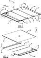
Figure 1 is right side rear perspective view of a tonneau cover assembly according to the present invention, with the cover material omitted for clarity; -
Figure 2 is an exploded view of the tonneau cover assembly shown from the left side rear perspective, in accordance with the present invention; -
Figure 3 is an enlarged rear perspective view of a portion of a front attachment assembly ofFigure 1 including a front attachment block connected to a bulkhead bow and a first tension cable, in accordance with the present invention; -
Figure 4 is a front perspective view of the front attachment assembly, in accordance with the present invention; -
Figure 5 is an exploded front view of the front attachment assembly according to the present invention; -
Figure 6 is an enlarged view of a portion of a rear attachment assembly ofFigure 1 including a rear attachment block connected to the first tension cable, in accordance with the present invention; -
Figure 7 is an exploded view of the rear attachment block and a partial opening feature, according to an embodiment of the present invention; and, -
Figure 8 is an enlarged rear perspective view of a portion ofFigure 1 showing one end of each of a pair of cover management bows, according to an embodiment of the present invention. - The following description of the preferred embodiment(s) is merely exemplary in nature and is in no way intended to limit the invention, its application, or uses.
- Referring to the figures generally, the term "front" refers to the front of the vehicle, cab area, as indicated by the arrow.
- Referring to
Figures 1-8 generally, there is generally provided a tonneau cover assembly shown generally at 10 having acover 12, e.g., fabric material, soft or flexible material, vinyl or any other suitable material and combinations thereof depending on the application. Thetonneau cover assembly 10 also has afront attachment assembly 14,rear attachment assembly 16 and at least one, preferably, a plurality of,cover management bows 18. Thesecover management bows 18, most preferably, two bows, are center fabric management bows located between thefront attachment assembly 14 andrear attachment assembly 16 running cross bed. - The
tonneau cover assembly 10 is provided with atensioning system 21 including at least afirst tension cable 20 and asecond tension cable 22 operably connected to front and rear attachment blocks, as will be explained in greater detail below. The cables are of the same or different predetermined suitable type(s) and diameter(s) for providing predetermined tension and tension release forces, dependant on the application. Thecable assembly 21 allows thetonneau system 10 to tension thetop cover 12, provides tension along the side of the cover to seal the cover to the bedside of the vehicle, and provides side to side location to assist in locating thecover 12 andfabric management bows 18. - Preferably, the
cables cover 12. - The
front attachment assembly 14 includes a pair offront attachment blocks 24 each connected to the respective ends of afirst bow 26 that is a front bulkhead bow. Thefront attachment blocks 24 provide a no drill attachment toward the bulkhead of the cargo bed. Anattachment arm 28 is operably connected to either of thefront attachment blocks 24 for attaching the front of theassembly 10, as will be explained in greater detail below. A cable attachment feature 30, e.g., with a first aperture, is formed in both of thefront attachment blocks 24 allowing for first mounting locations for thecable tensioning system 21. The first aperture preferably is formed on this outward feature of both of the front attachment blocks 24 for connecting both the first andsecond tension cables - Referring to the Figures generally, and more particularly to
Figures 3-5 , in a preferred embodiment, theattachment arm 28 is generally U-shaped, with two lower depending arms, and is sized to partially fit within anopening 31 formed in thefront attachment blocks 24. At least onefirst fastener 32, e.g., an attachment bolt, is extendable through at least asecond aperture 34 provided on one of the lower depending arms of theattachment arm 28 and athird aperture 36 formed in afirst brace 38. Asecond brace 39 is held, e.g., using adhesive and/or fastener(s), against the inside of the other lower depending arm for mounting to the vehicle. Thus, once thefirst bow 26, or "front bulkhead" referred to interchangeably herein, is put in place on the vehicle and then thefastener 32 is tightened, this draws theattachment arm 28 rearward fixing and sealing thefront bulkhead 26 to the bulkhead of the vehicle's bed. - The first pair of
front attachment blocks 24 are also provided with at least onefirst mounting bracket 40, preferably two side-by-side, to connect to thefirst bow 26. In a preferred embodiment, arespective mounting bracket 40 slides into each end of thefirst bow 26 and fasteners, e.g., bolts, are provided to fix thefirst bow 26 to thefirst mounting bracket 40. - Referring to the Figures generally, and more particularly to
Figures 1-2 and6-7 , therear attachment assembly 16 allows tension to be applied using thecable tension system 21, eliminating the need for side rails to seal thetonneau cover 12 to the vehicle bed. A pair of rear attachment blocks 42, or "rear tension block" referred to interchangeably herein, are both operably connected to arear bar 44 or bow,cross member 46, and aconnector bar 48, which is a release latch connector bar forming part of a release latch mechanism indicated generally at 50. Therelease latch mechanism 50 has a pair of release latches 52 operably connected to respective rear attachment blocks 42. - Both the right and left hand release latches 52 are tied together so that only one side needs to be operated to open both latches 52. A
fourth aperture 54 or a boss is provided on the block of the rear attachment blocks 42 and aligns with afifth aperture 56 or a boss provided on the release latches 52 for receiving theconnector bar 48. - A second
cable attachment feature 60, e.g., with a sixth aperture, is provided on both of the rear attachment blocks 42 allowing for mounting locations for thecable tensioning system 21. The sixth aperture preferably is formed on an outward feature of both of the rear attachment blocks 42 for connecting both the first andsecond tension cables - The pair of rear attachment blocks 42 are also provided with at least one
second mounting bracket 62 to connect to the ends of thecross member 46. In a preferred embodiment the second mountingbracket 62 slide into the ends of thecross member 46 and at least one fastener, e.g., bolts, are provided to fix thecross member 46 to thebrackets 62. - Preferably, a pair of rear mounting brackets indicated generally at 64 (see
Figs. 1-2 ) are provided. - In one preferred embodiment, the pair of rear attachment blocks 42 provides the
cables brackets 64 to provide the tension on the whole system. Therelease latch mechanism 50 is provided with the rear attachment blocks 42 to keep the tonneau securely closed until operated. Therelease latch mechanism 50 holds the tonneau in the closed position tension state to keep the tonneau secured and tight until the cover is opened by an operator. The right and left side latches 52,52 are operably linked together such that only one of theselatches latches brackets 64 provide a location for the rear attachment blocks 42 to engage and provide system tension. Thebrackets 64 are a bolt-on feature, and, alternatively, a feature that is incorporated in the vehicle bed without the need of the additional bracket. The front attachment blocks 24 provide thecable system 21 with forward mounting locations for thecables front bulkhead bow 26 to the bulkhead of the vehicle bed, preferably, without the need to drill attachment holes. Optionally, a soft cover or boot cover is operably attached to thefront bulkhead bow 26 that wraps and protects thetop cover 12 and assembly components when thecover 12 is opened and rolled up to the front of the vehicle bed in the stowed position. - Referring to the Figures generally, and more particularly to
Figure 8 , where the vehicle bedrails are omitted for clarity, in a preferred embodiment, the cover management bows 18 or fabric management bows are operably provided with operably profiled/configured ends for preventing undesirable movement on the existing bed rails. Using aflat edge feature 66, the ends touch off on the vehicle bed rails setting the height of thebows 18, and therefore thecover 12. Theflat edge 66 sits substantially flat on top of the bedrail such that thebows 18 cannot drop into the bed of the vehicle. An operable predetermined step feature formed in the bottom of the ends helps to set side to side positioning against the vehicle bed sides. By way of example, a step on the bottom drops in and sits just inside the bedrail such that the end cannot move too far either side. The flat edge is integrally formed with or an add one feature to thebows 18. Most preferably, the flat edge features 66 are molded bow ends operably connected to the fabric management bows 18 such that the bow ends lay on top of the predetermined vehicle bed section providing up/down engagement and side to side location and engagement, eliminating the need of a side rail to provide these engagements. Preferably, the molded bow ends are connected to the underside of thecover 12 by adhesive and/or sewn to the cover, and form a pocket to receive thebow 18 ends. - Referring to
Figures 1-8 generally, thetonneau cover assembly 10 eliminates side rails from the system. In accordance with the present invention, the cable tensioning system incorporatescables cover 12 tension and seal thecover 12 to the vehicle body. Theassembly 10 uses the bedside to locate the fabric management bows 18, 18 and cover 12 in their side to side and height orientations. The rear engagement feature, e.g., rear mountingbrackets 64, can be an additional bracket as shown or incorporated into the bed. The front engagement to the bed feature, e.g.,attachment arms 28, are drawing up on the bulkhead to locate/attach/seal. A significant advantage over conventional systems is the use of connected right and left hand latches 52,52 on a tonneau cover. Theassembly 10 optionally includes an integrated fabric boot cover to protect the stowed system when rolled and stowed. Depending on the application, alternative stowing methods are contemplated without deviation from the present invention. - The description of the invention is merely exemplary in nature and, thus, variations that do not depart from the invention are intended to be within the scope of the invention. Such variations are not to be regarded as a departure from the scope of the invention, which is defined in the claims.
Claims (14)
- A tonneau cover assembly (10) for a vehicle, comprising:a tensioning system (21) to tension a top cover (12) by providing tension along the sides of the top cover and to seal the top cover to a cargo bed of a vehicle;a front attachment assembly (14) operably connected at a bulkhead of the vehicle, said front attachment assembly providing a pair of first mounting locations for the tensioning system;a rear attachment assembly (16) operably connected to the vehicle and to the top cover, said rear attachment assembly providing a pair of second mounting locations for the tensioning system; and,a plurality of cover management bows including a flat surface at both ends that sets the location of the cover management bows on bed rails of the vehicle without requiring side rails on the tonneau cover assembly;characterised in that the tensioning system includes first and second cables (20, 22) running fore/aft along respective bed rails of the vehicle to tension the top cover;wherein said first and second cables are connected to the sides of the top cover;wherein each cable has a first end and a second end; andwherein a first end of each cable is fixedly connected to a respective first mounting location, and a second end of each cable is fixedly connected to a respective second mounting location.
- The tonneau cover (10) assembly of claim 1, wherein the front attachment assembly further includes a pair of front attachment blocks (24) each including a first cable attachment feature with an aperture for connecting one of the first and second cables.
- The tonneau cover assembly of claim 1, wherein the rear attachment assembly (16) further includes a pair of rear attachment blocks (42) each including a second cable attachment feature with an aperture for connecting one of the first and second cables.
- The tonneau cover assembly of claim 3, wherein the rear attachment assembly further includes a pair of rear mounting brackets operably connected to the vehicle and providing a place for the rear attachment blocks to engage and provide system tension.
- The tonneau cover assembly of claim 3, further including a rear cross member operably connected to the pair of rear attachment blocks.
- The tonneau cover assembly of claim 3, further including a release latch mechanism operably coupled to the pair of rear attachment blocks operable to selectively release tension to open the rear attachment assembly with the top cover to a stowed position.
- The tonneau cover assembly of claim 6, wherein the release latch mechanism includes two latches operably linked together and releasing one latch causes the other linked latch to also release.
- The tonneau cover assembly of claim 2 wherein the front attachment assembly further comprises a front bulkhead bow operably connected to the pair of front attachment blocks and operably connected to the top cover.
- The tonneau cover assembly of claim 8, wherein the front attachment blocks each further comprise:an attachment arm for fitting onto the vehicle bulkhead, the attachment arm having a second aperture;an opening for receiving a portion of the attachment arm;a first brace with a third aperture, wherein the first brace is sized to fit against the outside of the opening; and,at least one fastener;wherein the at least one fastener extends through the second and third apertures, and the attachment arm is drawn rearward when the at least one fastener is tightened to attach to the vehicle bulkhead and seal the front bulkhead bow to the bulkhead of the cargo bed.
- The tonneau cover assembly of claim 2, wherein:
the ends of the cover management bows have a flat bottom surface that contacts the vehicle's bed rails setting the height and location of the cover management bows. - The tonneau cover assembly of claim 1, wherein:the front attachment assembly includes a pair of front attachment blocks each connected to one of the cables, and operably connected to a bulkhead bow for sealing with a bulkhead of the vehicle; andthe rear attachment assembly includes a pair of rear attachment blocks each connected to one of the cables at the rear of the vehicle, and operably connected to a rear latch mechanism to keep the cover securely closed until selectively operated to an open position; andthe tonneau cover assembly further comprises:at least one rear bar operably coupled to the pair of rear attachment blocks and operably connected to the top cover;a plurality of rear mounting brackets operably connected to the vehicle bed or integrated as part of the vehicle bed, said rear mounting brackets providing a location for both ends of the rear attachment assembly to engage and provide tonneau cover assembly tension; and,at least one fabric management bow operably connected to the top cover and having ends that set the height and location of a said cover management bow on the vehicle bedside;wherein the cable tensioning system allows the tonneau cover assembly to tension the top cover, provides tension along the sides of the top cover to seal the top cover against the bedside of the vehicle, and provides cross car location to assist in locating the top cover and fabric management bows.
- The tonneau cover assembly of claim 9, wherein the rear latching mechanism further comprises a pair of release latches connected by a connector bar, where release of one latch allows the other latch to release simultaneously.
- The tonneau cover assembly of claim 2 or claim 9, further comprising a bulkhead bow operably connected to the pair of front attachment blocks and operably connected to the top cover.
- The tonneau cover assembly of claim 11, wherein the front attachment blocks each further comprise:an attachment arm for fitting onto the vehicle bulkhead, the attachment arm having a second aperture;an opening for receiving a portion of the attachment arm;a first brace with a third aperture, wherein the first brace is sized to fit against the outside of the opening; and,at least one fastener;wherein the at least one fastener extends through the second and third apertures, and the attachment arm is drawn rearward when the at least one fastener is tightened to attach to the vehicle bulkhead and seal the front bulkhead bow to the bulkhead of the cargo bed.
Applications Claiming Priority (1)
| Application Number | Priority Date | Filing Date | Title |
|---|---|---|---|
| US201562147856P | 2015-04-15 | 2015-04-15 |
Publications (2)
| Publication Number | Publication Date |
|---|---|
| EP3081417A1 EP3081417A1 (en) | 2016-10-19 |
| EP3081417B1 true EP3081417B1 (en) | 2020-03-18 |
Family
ID=55802230
Family Applications (1)
| Application Number | Title | Priority Date | Filing Date |
|---|---|---|---|
| EP16165631.9A Active EP3081417B1 (en) | 2015-04-15 | 2016-04-15 | Tonneau cover having tensioning system with cables |
Country Status (3)
| Country | Link |
|---|---|
| US (2) | US9889789B2 (en) |
| EP (1) | EP3081417B1 (en) |
| CN (1) | CN106043098A (en) |
Cited By (1)
| Publication number | Priority date | Publication date | Assignee | Title |
|---|---|---|---|---|
| US20250269705A1 (en) * | 2024-02-24 | 2025-08-28 | Yunyan He | Tri-fold semi-embedded cover for front rail with locks |
Families Citing this family (9)
| Publication number | Priority date | Publication date | Assignee | Title |
|---|---|---|---|---|
| US10363801B2 (en) | 2015-11-03 | 2019-07-30 | Bestop, Inc. | Tonneau cover access panel |
| US10239394B2 (en) * | 2015-11-03 | 2019-03-26 | Bestop, Inc. | Tonneau cover access panel |
| US10336221B2 (en) * | 2017-10-18 | 2019-07-02 | Ami Industries, Inc. | Stowable seat with backrest release |
| US10800234B2 (en) | 2017-10-27 | 2020-10-13 | Truck Associates Group, LLC | Folding cover attachment systems |
| US10737563B2 (en) | 2018-01-09 | 2020-08-11 | Tectum Holdings Inc. | Bias regulated rolling truck bed cover |
| CN208665042U (en) * | 2018-08-02 | 2019-03-29 | 常州市盛沃国际贸易有限公司 | The soft compartment cover of picking-up vehicle |
| US11299021B2 (en) | 2019-07-17 | 2022-04-12 | Truck Accessories Group, Llc | Multi-panel tonneau cover |
| US11097605B2 (en) | 2019-10-24 | 2021-08-24 | Extang Corporation | Auto latch for tonneau cover system |
| BR112021013417B1 (en) | 2021-06-17 | 2024-01-16 | Keko Acessórios S/A | MARINE CANOPY FIXING AND ASSEMBLY SYSTEM |
Family Cites Families (6)
| Publication number | Priority date | Publication date | Assignee | Title |
|---|---|---|---|---|
| US4813734A (en) | 1986-12-29 | 1989-03-21 | Richard Hoover | Removable camper shell apparatus for trucks |
| US5263761A (en) * | 1992-01-21 | 1993-11-23 | Cr&I Inc. | Vehicle modular rail system |
| US6257647B1 (en) | 1998-01-16 | 2001-07-10 | Bestop, Inc. | Tonneau cover system |
| US6981734B2 (en) | 2003-01-28 | 2006-01-03 | Mountain Tarp And Awning, Inc. | Tarpaulin system for an open-top cargo hold |
| US6948760B2 (en) * | 2003-05-28 | 2005-09-27 | Webasto Sunroofs, Inc. | Cover assembly for a vehicle bed and method for mounting the same |
| US8146981B2 (en) | 2010-07-28 | 2012-04-03 | Magna International Inc. | Cable roll up tonneau |
-
2016
- 2016-04-14 US US15/099,187 patent/US9889789B2/en active Active
- 2016-04-15 EP EP16165631.9A patent/EP3081417B1/en active Active
- 2016-04-15 CN CN201610237413.0A patent/CN106043098A/en active Pending
-
2018
- 2018-01-09 US US15/865,338 patent/US10384588B2/en active Active
Non-Patent Citations (1)
| Title |
|---|
| None * |
Cited By (1)
| Publication number | Priority date | Publication date | Assignee | Title |
|---|---|---|---|---|
| US20250269705A1 (en) * | 2024-02-24 | 2025-08-28 | Yunyan He | Tri-fold semi-embedded cover for front rail with locks |
Also Published As
| Publication number | Publication date |
|---|---|
| US20180126895A1 (en) | 2018-05-10 |
| US20160304024A1 (en) | 2016-10-20 |
| US9889789B2 (en) | 2018-02-13 |
| US10384588B2 (en) | 2019-08-20 |
| EP3081417A1 (en) | 2016-10-19 |
| CN106043098A (en) | 2016-10-26 |
Similar Documents
| Publication | Publication Date | Title |
|---|---|---|
| US10384588B2 (en) | Cable tonneau cover | |
| US20220242212A1 (en) | Tonneau cover access panel | |
| US10363801B2 (en) | Tonneau cover access panel | |
| EP3863875B1 (en) | Tonneau cover tie-down assembly | |
| US9376002B2 (en) | Combination roof rack and removable soft top | |
| US20140117653A1 (en) | Top for a vehicle | |
| US8146981B2 (en) | Cable roll up tonneau | |
| CN101500846B (en) | Slide out cargo floor | |
| US20150123421A1 (en) | Vehicle bed cover system and storage assembly | |
| US11021046B2 (en) | Retractable overhead shade | |
| US10562460B2 (en) | Vehicle multi-function accessory rail systems | |
| US20100060035A1 (en) | Removable Chassis Skirt | |
| US10647243B2 (en) | Under-floor truck deck tie-down device and truck deck and truck having the same | |
| US9950598B2 (en) | Integrated rod attachment top | |
| US2998279A (en) | Vehicle divider | |
| EP3670222A2 (en) | Vehicle canopy adapter and canopies | |
| US8235266B2 (en) | Rack strap extension systems for vehicle bike racks | |
| US20180334199A1 (en) | Vehicle Having a Load Carrying Deck and Attachment Device for the Same | |
| US10065567B2 (en) | Auxiliary storage mounting arrangement for a vehicle | |
| US9162629B2 (en) | Extendable vehicle rack arrangement | |
| US10160300B2 (en) | Vehicle soft top support bracket system | |
| US20110243682A1 (en) | Cargo hold-down device for a load-carrying bed of a vehicle | |
| JP2009101881A (en) | Roof reinforcing structure |
Legal Events
| Date | Code | Title | Description |
|---|---|---|---|
| PUAI | Public reference made under article 153(3) epc to a published international application that has entered the european phase |
Free format text: ORIGINAL CODE: 0009012 |
|
| AK | Designated contracting states |
Kind code of ref document: A1 Designated state(s): AL AT BE BG CH CY CZ DE DK EE ES FI FR GB GR HR HU IE IS IT LI LT LU LV MC MK MT NL NO PL PT RO RS SE SI SK SM TR |
|
| AX | Request for extension of the european patent |
Extension state: BA ME |
|
| STAA | Information on the status of an ep patent application or granted ep patent |
Free format text: STATUS: REQUEST FOR EXAMINATION WAS MADE |
|
| 17P | Request for examination filed |
Effective date: 20170418 |
|
| RBV | Designated contracting states (corrected) |
Designated state(s): AL AT BE BG CH CY CZ DE DK EE ES FI FR GB GR HR HU IE IS IT LI LT LU LV MC MK MT NL NO PL PT RO RS SE SI SK SM TR |
|
| GRAP | Despatch of communication of intention to grant a patent |
Free format text: ORIGINAL CODE: EPIDOSNIGR1 |
|
| STAA | Information on the status of an ep patent application or granted ep patent |
Free format text: STATUS: GRANT OF PATENT IS INTENDED |
|
| INTG | Intention to grant announced |
Effective date: 20190925 |
|
| GRAS | Grant fee paid |
Free format text: ORIGINAL CODE: EPIDOSNIGR3 |
|
| GRAA | (expected) grant |
Free format text: ORIGINAL CODE: 0009210 |
|
| STAA | Information on the status of an ep patent application or granted ep patent |
Free format text: STATUS: THE PATENT HAS BEEN GRANTED |
|
| AK | Designated contracting states |
Kind code of ref document: B1 Designated state(s): AL AT BE BG CH CY CZ DE DK EE ES FI FR GB GR HR HU IE IS IT LI LT LU LV MC MK MT NL NO PL PT RO RS SE SI SK SM TR |
|
| REG | Reference to a national code |
Ref country code: GB Ref legal event code: FG4D |
|
| REG | Reference to a national code |
Ref country code: DE Ref legal event code: R096 Ref document number: 602016031848 Country of ref document: DE |
|
| REG | Reference to a national code |
Ref country code: AT Ref legal event code: REF Ref document number: 1245518 Country of ref document: AT Kind code of ref document: T Effective date: 20200415 Ref country code: IE Ref legal event code: FG4D |
|
| PG25 | Lapsed in a contracting state [announced via postgrant information from national office to epo] |
Ref country code: NO Free format text: LAPSE BECAUSE OF FAILURE TO SUBMIT A TRANSLATION OF THE DESCRIPTION OR TO PAY THE FEE WITHIN THE PRESCRIBED TIME-LIMIT Effective date: 20200618 Ref country code: FI Free format text: LAPSE BECAUSE OF FAILURE TO SUBMIT A TRANSLATION OF THE DESCRIPTION OR TO PAY THE FEE WITHIN THE PRESCRIBED TIME-LIMIT Effective date: 20200318 Ref country code: RS Free format text: LAPSE BECAUSE OF FAILURE TO SUBMIT A TRANSLATION OF THE DESCRIPTION OR TO PAY THE FEE WITHIN THE PRESCRIBED TIME-LIMIT Effective date: 20200318 |
|
| REG | Reference to a national code |
Ref country code: NL Ref legal event code: MP Effective date: 20200318 |
|
| PG25 | Lapsed in a contracting state [announced via postgrant information from national office to epo] |
Ref country code: GR Free format text: LAPSE BECAUSE OF FAILURE TO SUBMIT A TRANSLATION OF THE DESCRIPTION OR TO PAY THE FEE WITHIN THE PRESCRIBED TIME-LIMIT Effective date: 20200619 Ref country code: BG Free format text: LAPSE BECAUSE OF FAILURE TO SUBMIT A TRANSLATION OF THE DESCRIPTION OR TO PAY THE FEE WITHIN THE PRESCRIBED TIME-LIMIT Effective date: 20200618 Ref country code: HR Free format text: LAPSE BECAUSE OF FAILURE TO SUBMIT A TRANSLATION OF THE DESCRIPTION OR TO PAY THE FEE WITHIN THE PRESCRIBED TIME-LIMIT Effective date: 20200318 Ref country code: SE Free format text: LAPSE BECAUSE OF FAILURE TO SUBMIT A TRANSLATION OF THE DESCRIPTION OR TO PAY THE FEE WITHIN THE PRESCRIBED TIME-LIMIT Effective date: 20200318 Ref country code: LV Free format text: LAPSE BECAUSE OF FAILURE TO SUBMIT A TRANSLATION OF THE DESCRIPTION OR TO PAY THE FEE WITHIN THE PRESCRIBED TIME-LIMIT Effective date: 20200318 |
|
| REG | Reference to a national code |
Ref country code: LT Ref legal event code: MG4D |
|
| PG25 | Lapsed in a contracting state [announced via postgrant information from national office to epo] |
Ref country code: NL Free format text: LAPSE BECAUSE OF FAILURE TO SUBMIT A TRANSLATION OF THE DESCRIPTION OR TO PAY THE FEE WITHIN THE PRESCRIBED TIME-LIMIT Effective date: 20200318 |
|
| PG25 | Lapsed in a contracting state [announced via postgrant information from national office to epo] |
Ref country code: CZ Free format text: LAPSE BECAUSE OF FAILURE TO SUBMIT A TRANSLATION OF THE DESCRIPTION OR TO PAY THE FEE WITHIN THE PRESCRIBED TIME-LIMIT Effective date: 20200318 Ref country code: PT Free format text: LAPSE BECAUSE OF FAILURE TO SUBMIT A TRANSLATION OF THE DESCRIPTION OR TO PAY THE FEE WITHIN THE PRESCRIBED TIME-LIMIT Effective date: 20200812 Ref country code: RO Free format text: LAPSE BECAUSE OF FAILURE TO SUBMIT A TRANSLATION OF THE DESCRIPTION OR TO PAY THE FEE WITHIN THE PRESCRIBED TIME-LIMIT Effective date: 20200318 Ref country code: LT Free format text: LAPSE BECAUSE OF FAILURE TO SUBMIT A TRANSLATION OF THE DESCRIPTION OR TO PAY THE FEE WITHIN THE PRESCRIBED TIME-LIMIT Effective date: 20200318 Ref country code: SK Free format text: LAPSE BECAUSE OF FAILURE TO SUBMIT A TRANSLATION OF THE DESCRIPTION OR TO PAY THE FEE WITHIN THE PRESCRIBED TIME-LIMIT Effective date: 20200318 Ref country code: EE Free format text: LAPSE BECAUSE OF FAILURE TO SUBMIT A TRANSLATION OF THE DESCRIPTION OR TO PAY THE FEE WITHIN THE PRESCRIBED TIME-LIMIT Effective date: 20200318 Ref country code: SM Free format text: LAPSE BECAUSE OF FAILURE TO SUBMIT A TRANSLATION OF THE DESCRIPTION OR TO PAY THE FEE WITHIN THE PRESCRIBED TIME-LIMIT Effective date: 20200318 Ref country code: IS Free format text: LAPSE BECAUSE OF FAILURE TO SUBMIT A TRANSLATION OF THE DESCRIPTION OR TO PAY THE FEE WITHIN THE PRESCRIBED TIME-LIMIT Effective date: 20200718 |
|
| REG | Reference to a national code |
Ref country code: AT Ref legal event code: MK05 Ref document number: 1245518 Country of ref document: AT Kind code of ref document: T Effective date: 20200318 |
|
| REG | Reference to a national code |
Ref country code: CH Ref legal event code: PL |
|
| REG | Reference to a national code |
Ref country code: DE Ref legal event code: R097 Ref document number: 602016031848 Country of ref document: DE |
|
| PG25 | Lapsed in a contracting state [announced via postgrant information from national office to epo] |
Ref country code: MC Free format text: LAPSE BECAUSE OF FAILURE TO SUBMIT A TRANSLATION OF THE DESCRIPTION OR TO PAY THE FEE WITHIN THE PRESCRIBED TIME-LIMIT Effective date: 20200318 |
|
| PLBE | No opposition filed within time limit |
Free format text: ORIGINAL CODE: 0009261 |
|
| STAA | Information on the status of an ep patent application or granted ep patent |
Free format text: STATUS: NO OPPOSITION FILED WITHIN TIME LIMIT |
|
| PG25 | Lapsed in a contracting state [announced via postgrant information from national office to epo] |
Ref country code: LU Free format text: LAPSE BECAUSE OF NON-PAYMENT OF DUE FEES Effective date: 20200415 Ref country code: ES Free format text: LAPSE BECAUSE OF FAILURE TO SUBMIT A TRANSLATION OF THE DESCRIPTION OR TO PAY THE FEE WITHIN THE PRESCRIBED TIME-LIMIT Effective date: 20200318 Ref country code: CH Free format text: LAPSE BECAUSE OF NON-PAYMENT OF DUE FEES Effective date: 20200430 Ref country code: DK Free format text: LAPSE BECAUSE OF FAILURE TO SUBMIT A TRANSLATION OF THE DESCRIPTION OR TO PAY THE FEE WITHIN THE PRESCRIBED TIME-LIMIT Effective date: 20200318 Ref country code: AT Free format text: LAPSE BECAUSE OF FAILURE TO SUBMIT A TRANSLATION OF THE DESCRIPTION OR TO PAY THE FEE WITHIN THE PRESCRIBED TIME-LIMIT Effective date: 20200318 Ref country code: IT Free format text: LAPSE BECAUSE OF FAILURE TO SUBMIT A TRANSLATION OF THE DESCRIPTION OR TO PAY THE FEE WITHIN THE PRESCRIBED TIME-LIMIT Effective date: 20200318 Ref country code: LI Free format text: LAPSE BECAUSE OF NON-PAYMENT OF DUE FEES Effective date: 20200430 |
|
| REG | Reference to a national code |
Ref country code: BE Ref legal event code: MM Effective date: 20200430 |
|
| 26N | No opposition filed |
Effective date: 20201221 |
|
| PG25 | Lapsed in a contracting state [announced via postgrant information from national office to epo] |
Ref country code: BE Free format text: LAPSE BECAUSE OF NON-PAYMENT OF DUE FEES Effective date: 20200430 Ref country code: PL Free format text: LAPSE BECAUSE OF FAILURE TO SUBMIT A TRANSLATION OF THE DESCRIPTION OR TO PAY THE FEE WITHIN THE PRESCRIBED TIME-LIMIT Effective date: 20200318 |
|
| PG25 | Lapsed in a contracting state [announced via postgrant information from national office to epo] |
Ref country code: IE Free format text: LAPSE BECAUSE OF NON-PAYMENT OF DUE FEES Effective date: 20200415 Ref country code: FR Free format text: LAPSE BECAUSE OF NON-PAYMENT OF DUE FEES Effective date: 20200518 |
|
| PG25 | Lapsed in a contracting state [announced via postgrant information from national office to epo] |
Ref country code: SI Free format text: LAPSE BECAUSE OF FAILURE TO SUBMIT A TRANSLATION OF THE DESCRIPTION OR TO PAY THE FEE WITHIN THE PRESCRIBED TIME-LIMIT Effective date: 20200318 |
|
| PGFP | Annual fee paid to national office [announced via postgrant information from national office to epo] |
Ref country code: GB Payment date: 20220325 Year of fee payment: 7 |
|
| PG25 | Lapsed in a contracting state [announced via postgrant information from national office to epo] |
Ref country code: TR Free format text: LAPSE BECAUSE OF FAILURE TO SUBMIT A TRANSLATION OF THE DESCRIPTION OR TO PAY THE FEE WITHIN THE PRESCRIBED TIME-LIMIT Effective date: 20200318 Ref country code: MT Free format text: LAPSE BECAUSE OF FAILURE TO SUBMIT A TRANSLATION OF THE DESCRIPTION OR TO PAY THE FEE WITHIN THE PRESCRIBED TIME-LIMIT Effective date: 20200318 Ref country code: CY Free format text: LAPSE BECAUSE OF FAILURE TO SUBMIT A TRANSLATION OF THE DESCRIPTION OR TO PAY THE FEE WITHIN THE PRESCRIBED TIME-LIMIT Effective date: 20200318 |
|
| PG25 | Lapsed in a contracting state [announced via postgrant information from national office to epo] |
Ref country code: MK Free format text: LAPSE BECAUSE OF FAILURE TO SUBMIT A TRANSLATION OF THE DESCRIPTION OR TO PAY THE FEE WITHIN THE PRESCRIBED TIME-LIMIT Effective date: 20200318 Ref country code: AL Free format text: LAPSE BECAUSE OF FAILURE TO SUBMIT A TRANSLATION OF THE DESCRIPTION OR TO PAY THE FEE WITHIN THE PRESCRIBED TIME-LIMIT Effective date: 20200318 |
|
| PGFP | Annual fee paid to national office [announced via postgrant information from national office to epo] |
Ref country code: DE Payment date: 20220318 Year of fee payment: 7 |
|
| REG | Reference to a national code |
Ref country code: DE Ref legal event code: R119 Ref document number: 602016031848 Country of ref document: DE |
|
| GBPC | Gb: european patent ceased through non-payment of renewal fee |
Effective date: 20230415 |
|
| PG25 | Lapsed in a contracting state [announced via postgrant information from national office to epo] |
Ref country code: GB Free format text: LAPSE BECAUSE OF NON-PAYMENT OF DUE FEES Effective date: 20230415 |
|
| PG25 | Lapsed in a contracting state [announced via postgrant information from national office to epo] |
Ref country code: GB Free format text: LAPSE BECAUSE OF NON-PAYMENT OF DUE FEES Effective date: 20230415 Ref country code: DE Free format text: LAPSE BECAUSE OF NON-PAYMENT OF DUE FEES Effective date: 20231103 |