EP3081386A1 - Sheet post-processing apparatus - Google Patents
Sheet post-processing apparatus Download PDFInfo
- Publication number
- EP3081386A1 EP3081386A1 EP16164703.7A EP16164703A EP3081386A1 EP 3081386 A1 EP3081386 A1 EP 3081386A1 EP 16164703 A EP16164703 A EP 16164703A EP 3081386 A1 EP3081386 A1 EP 3081386A1
- Authority
- EP
- European Patent Office
- Prior art keywords
- sheets
- adhesive
- binding
- binding unit
- unit
- Prior art date
- Legal status (The legal status is an assumption and is not a legal conclusion. Google has not performed a legal analysis and makes no representation as to the accuracy of the status listed.)
- Granted
Links
Images





Classifications
-
- B—PERFORMING OPERATIONS; TRANSPORTING
- B42—BOOKBINDING; ALBUMS; FILES; SPECIAL PRINTED MATTER
- B42C—BOOKBINDING
- B42C9/00—Applying glue or adhesive peculiar to bookbinding
- B42C9/0081—Applying glue or adhesive peculiar to bookbinding applying adhesive to individual sheets for binding them together
-
- B—PERFORMING OPERATIONS; TRANSPORTING
- B42—BOOKBINDING; ALBUMS; FILES; SPECIAL PRINTED MATTER
- B42B—PERMANENTLY ATTACHING TOGETHER SHEETS, QUIRES OR SIGNATURES OR PERMANENTLY ATTACHING OBJECTS THERETO
- B42B5/00—Permanently attaching together sheets, quires or signatures otherwise than by stitching
- B42B5/02—Permanently attaching together sheets, quires or signatures otherwise than by stitching by eyelets
-
- B—PERFORMING OPERATIONS; TRANSPORTING
- B42—BOOKBINDING; ALBUMS; FILES; SPECIAL PRINTED MATTER
- B42C—BOOKBINDING
- B42C1/00—Collating or gathering sheets combined with processes for permanently attaching together sheets or signatures or for interposing inserts
- B42C1/12—Machines for both collating or gathering and permanently attaching together the sheets or signatures
- B42C1/125—Sheet sorters combined with binding devices
-
- B—PERFORMING OPERATIONS; TRANSPORTING
- B42—BOOKBINDING; ALBUMS; FILES; SPECIAL PRINTED MATTER
- B42C—BOOKBINDING
- B42C19/00—Multi-step processes for making books
- B42C19/02—Multi-step processes for making books starting with single sheets
-
- B—PERFORMING OPERATIONS; TRANSPORTING
- B42—BOOKBINDING; ALBUMS; FILES; SPECIAL PRINTED MATTER
- B42C—BOOKBINDING
- B42C9/00—Applying glue or adhesive peculiar to bookbinding
- B42C9/0006—Applying glue or adhesive peculiar to bookbinding by applying adhesive to a stack of sheets
-
- B—PERFORMING OPERATIONS; TRANSPORTING
- B65—CONVEYING; PACKING; STORING; HANDLING THIN OR FILAMENTARY MATERIAL
- B65H—HANDLING THIN OR FILAMENTARY MATERIAL, e.g. SHEETS, WEBS, CABLES
- B65H37/00—Article or web delivery apparatus incorporating devices for performing specified auxiliary operations
- B65H37/02—Article or web delivery apparatus incorporating devices for performing specified auxiliary operations for applying adhesive
-
- B—PERFORMING OPERATIONS; TRANSPORTING
- B65—CONVEYING; PACKING; STORING; HANDLING THIN OR FILAMENTARY MATERIAL
- B65H—HANDLING THIN OR FILAMENTARY MATERIAL, e.g. SHEETS, WEBS, CABLES
- B65H37/00—Article or web delivery apparatus incorporating devices for performing specified auxiliary operations
- B65H37/04—Article or web delivery apparatus incorporating devices for performing specified auxiliary operations for securing together articles or webs, e.g. by adhesive, stitching or stapling
-
- B—PERFORMING OPERATIONS; TRANSPORTING
- B65—CONVEYING; PACKING; STORING; HANDLING THIN OR FILAMENTARY MATERIAL
- B65H—HANDLING THIN OR FILAMENTARY MATERIAL, e.g. SHEETS, WEBS, CABLES
- B65H43/00—Use of control, checking, or safety devices, e.g. automatic devices comprising an element for sensing a variable
Definitions
- Embodiments described herein relate generally to a technique for producing a sheet bundle by applying adhesive to sheets continuously fed one by one.
- a sheet post-processing apparatus in which sheets discharged from an image forming apparatus body are sequentially received, the sheets are discharged and stacked on a processing tray, and a sheet bundle is bound. Then, the sheet post-processing apparatus includes a adhesive application mechanism in which adhesive is applied to a portion corresponding to a predetermined binding margin of the sheet. An operation for loading the sheets on a adhesive application portion is sequentially repeated. A plurality of sheets are thereby produced in a bundle.
- a post-processing apparatus includes an adhesive binding unit that binds a plurality of sheets into a bundle.
- a controller sets an allowable binding number X of sheets capable of being subject to binding at one time in the adhesive binding apparatus.
- the controller sets a predetermined remaining number N of sheets.
- the controller receives a number A of the sheets instructed to be bound in the adhesive binding unit.
- the controller determines whether n>N or n ⁇ N.
- the adhesive binding unit binds the A number of the sheets into a single bundle when it is determined that n ⁇ N.
- the controller is configured to control the adhesive binding unit to process the remaining number of sheets counted by the counter when R>X according to a processing indicated by a received user instruction.
- the processing indicated by the received user instruction is selected from a display that displays a selectable first mode in which the remaining number of sheets counted by the counter when R>X is processed by binding as another single bundle in the adhesive binding unit and a selectable second mode in which the remaining number sheets counted by the counter when R>X is processed according to another processing that is not binding in the adhesive binding unit.
- the apparatus further comprises: a second binding unit configured to perform a second binding process different from the adhesive binding performed in the adhesive binding unit.
- the controller controls the second binding unit to perform the second binding process.
- the another processing is one of sorting and stapling.
- the adhesive binding unit applies an adhesive tape between each of the plurality of sheets.
- the adhesive binding unit applies a liquid adhesive between each of the plurality of sheets.
- the apparatus further comprises a punching unit configured to punch at least one hole in each the plurality of sheets conveyed from the image forming apparatus.
- the adhesive binding unit includes a pressing plate and a bottom plate configured to press the bundle therebetween.
- N is set so that a number X+N of the sheets is the maximum number of sheets that can be bound in a single bundle by the adhesive binding unit based on a thickness of each sheet and a distance between the pressing plate and the bottom plate.
- the apparatus makes it possible to set the sheets exceeding the predetermined number in the adhesive application mechanism.
- n>N the remaining number of sheets counted by the counter when R>X are processed according to a processing indicated by a received user instruction.
- the processing indicated by the received user instruction is selected from a display that displays a selectable first mode in which the counted remaining number of sheets when R>X is processed by binding as another single bundle in the adhesive binding unit and a selectable second mode in which the remaining number sheets counted by the counter when R>X is processed according to another processing that is not binding in the adhesive binding unit.
- the method further comprises the step of: performing, in a second binding unit, a second binding process different from the adhesive binding performed in the adhesive binding unit on the remaining number sheets counted for R>X when the second mode is selected.
- the another processing is one of sorting and stapling.
- the adhesive binding unit applies an adhesive tape between each of the plurality of sheets.
- the adhesive binding unit applies a liquid adhesive between each of the plurality of sheets.
- the method further comprises the step of: punching at least one hole in each the plurality of sheets conveyed from the image forming apparatus.
- the adhesive binding unit includes a pressing plate and a bottomplate configured to press the bundle therebetween, and N is set so that a number X+N of the sheets is the maximum number of sheets that can be bound in a single bundle by the adhesive binding unit based on a thickness of each sheet and a distance between the pressing plate and the bottom plate.
- the method according to the present invention makes it possible to set the sheets exceeding the predetermined number in the adhesive application mechanism.
- FIG. 1 is a schematic view illustrating a post-processing apparatus 1.
- the post-processing apparatus 1 receives a sheet discharged from an image forming apparatus 7 connected to the post-processing apparatus 1.
- the post-processing apparatus 1 performs various processes such as binding, folding, and drilling with respect to the sheets.
- FIG. 2 is a perspective view illustrating an adhesive binding process unit viewed from a processing tray side
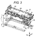
- FIG. 3 is a perspective view illustrating the adhesive binding process with periphery members removed.
- the post-processing apparatus 1 includes, for example, a binding unit T, a folding unit B, a stapler W, a punching unit 109, and the like for performing post-processing functions.
- the configuration of the post-processing apparatus 1 includes the binding unit T, the folding unit B, the stapler W, the punching unit 109, and the like.
- the post-processing apparatus 1 is not limited to the example, but includes at least the binding unit T.
- the sheet on which an image is formed in the image forming apparatus 7 passes through the punching unit 109.
- the hole punching is performed to the sheet by the punching unit 109 at this time point.
- a transporting destination of the sheet passed through the punching unit 109 is switched to one of a transportation path 110 and a transportation path 108 by a flapper 117.
- the sheet is guided to the transportation path 108 by the flapper 117 and is further guided to a transportation path 119 by a flapper 107, and then is discharged to a first discharge tray 106.
- the sheet guided to the transportation path 108 is further guided to a transportation path 120 by the flapper 107 and is discharged on a temporary tray 104 (so-called buffer tray).
- the sheet discharged on the temporary tray 104 is knocked off by a rotating paddle 103 rotating counterclockwise on a paper surface of FIG. 1 and is stacked on a processing tray 102.
- the binding unit T includes a adhesive application unit 101 that performs adhesive application on an upper surface of the sheet stacked on the processing tray 102.
- the binding unit T performs the adhesive application on the upper surface of the sheet with the adhesive application unit 101 whenever the sheet is stacked on the processing tray 102. However, for example, if a sheet bundle of 10 sheets being bound, adhesive application is not performed on an upper surface of the tenth sheet (the uppermost sheet stacked on the ninth sheet).
- the adhesive application unit 101 includes an adhesive applying unit U that is removably stored in a holder 11.
- a pressing force receiving stand 12 is disposed below the holder 11.
- the holder 11 is movably held in a guide shaft 13 and can move in an axial direction.
- the distance H corresponds to the number of sheets that is bound at one time.
- a pressing plate 14 is disposed between a lower end of the holder 11 and the uppermost surface of the sheet bundle stacked on the pressing force receiving stand 12.
- the maximum height (maximum number of sheets) of the sheet bundle becomes a height (h) which is smaller than a height H, considering an arrangement space of the pressing plate 14 or the like.
- the binding number of sheets corresponding to the height (hereinafter, referred to as a binding limit height) h is the allowable binding number (X) of sheets.
- the number of sheets corresponding to the binding limit height h is different depending on the thickness of the sheets. Furthermore, a thickness of the adhesive used for the adhesive binding is not necessarily constant. Thus, in the embodiment, the allowable binding number (X) of sheets corresponding to the binding limit height h is set to be a small number of sheets and the binding is performed with a certain degree of allowance.
- the height thereof practically may be the binding limit height h or less, even with the exceeded number of sheets.
- the number of sheets in which the predetermined number (N) of sheets is added to the allowable binding number (X) of sheets practically corresponds to the binding limit height h.
- the number (A) of sheets instructed to be printed exceeds the allowable binding number (X) of sheets, when the exceeded number of sheets (the remaining number (n) of sheets described below) is smaller than the predetermined number (N) of sheets (predetermined remaining number of sheets), the sheets are bound as one bundle.
- first and second pressing springs 17A and 17B- which may be tension springs, for example-are respectively disposed between right and left side surfaces of the holder 11 and a adhesive application unit substrate (not illustrated), and function to bias the holder 11 towards the pressing force receiving stand 12.
- the pressing plate 14 is formed with a concaved vertically cross-sectional shape in which flanges 142 rise upward from three sides of a rectangular plate-shaped bottom plate 141.
- a lower end of the holder 11 abuts upper surfaces of the flanges 142 so that an adhesive applying surface of the adhesive applying unit U does not directly abut the bottom plate 141.
- the adhesive applying unit U is the adhesive applying unit which causes the adhesive as adhesive for bonding the sheets each other to be applied to the sheet.
- the adhesive applying unit it is possible to employ a system in which the adhesive is applied by abutting mesh impregnated with liquid adhesive and the like.
- An adhesive binding position of the sheet mounted on the processing tray 102 is mounted on the pressing force receiving stand 12 in a state of abutting an abutting alignment position.
- the adhesive applying unit U applies the adhesive to a predetermined region of the upper surface of the sheet when being pressed by the spring forces of the first and second pressing springs 17A and 17B.
- the pressing plate 14 When the holder 11 moves up and down for applying the adhesive, the pressing plate 14 is held in a position retracted from the pressing force receiving stand 12.
- the pressing plate 14 is mounted on a pressing plate holding body 18.
- the pressing plate holding body 18 is fixed to rotation arms 19 and 20 disposed on upper and lower sides.
- the rotation arms 19 and 20 are mounted on the guide shaft 13 and can move in the axial direction and rotatably about the shaft.
- the upper holder arm 15 is disposed above the upper rotation arm 19.
- the upper rotation arm 19 is disposed above the lower holder arm 16.
- the lower rotation arm 20 is disposed below the lower holder arm 16.
- the pressing plate holding body 18 moves up and down following the up and down movement of the holder 11. Furthermore, the pressing plate 14 is capable of turning about the guide shaft 13 between a pressing position immediately above the pressing force receiving stand 12 and a non-pressing position retracted from the pressing force receiving stand 12.
- a turning spring 21- which may be a tension spring, for example-is disposed between the pressing plate holding body 18 and a adhesive application unit substrate (not illustrated), and biases the pressing plate 14 towards the non-pressing position.
- a turning drive unit drives the pressing plate 14 to be turned against the spring force of the turning spring 21.
- An up-down drive unit moves the holder 11 up and down against the spring forces of the first and second pressing springs 17A and 17B.
- the turning drive unit and the up-down drive unit may be configured to be driven by separate motors, however, in the embodiment, the up-down drive unit and the turning drive unit are configured to be driven by one motor M.
- a motor gear MG is mounted on a motor shaft MS of the motor M.
- the motor gear MG is meshed with an intermediate gear GI.
- a first transmission gear G1 having a coaxial small diameter is mounted on the intermediate gear GI.
- the first transmission gear G1 is meshed with a second transmission gear G2 having a large diameter.
- the second transmission gear G2 is mounted on a first rotation shaft 22.
- the up-down drive unit includes a disk-shaped first cam 23 fixed to the first rotation shaft 22.
- a second rotation shaft 24 is coaxially mounted on the first rotation shaft 22 from outside.
- the turning drive unit includes a second cam 25 fixed to the second rotation shaft 24.
- the first rotation shaft 22 and the second rotation shaft 24 are connected through a one-way clutch 26.
- the one-way clutch 26 transmits a rotational force to the second rotation shaft 24 and integrally rotates the first rotation shaft 22 and the second rotation shaft 24 counterclockwise.
- the first rotation shaft 22 rotates clockwise (CW)
- the one-way clutch 26 does not transmit the rotational force to the second rotation shaft 24 and only rotates the first rotation shaft 22 clockwise.
- a plate-shaped lifting cam follower 27 abuts a cam surface of the first cam 23 and is mounted on a lower portion of the holder 11.
- a rod-shaped turning cam follower 28 engages the cam surface of the second cam 25 and is passed through and fixed to base sides of the rotation arms 19 and 20.
- the motor M when the holder 11 moves up and down and the pressing plate 14 is held in the non-pressing position (illustrated in FIG. 6 ) to perform the adhesive application, the motor M is controlled so that the first rotation shaft 22 rotates clockwise. When pressing the sheet bundle to which the adhesive application is performed, the motor M is controlled so that the first rotation shaft 22 rotates counterclockwise.
- a cam top position (corresponding to the retracted position of the holder 11) of the first cam 23 is detected by a first phase sensor unit 29 provided in a leading end portion of the first rotation shaft 22.
- An engagement start position (corresponding to the non-pressing position) of the second cam 25 with the turning cam follower 28 is detected by a second phase sensor unit 30 provided in a leading end portion of the second rotation shaft 24.
- the first cam 23 may be configured with a true circular-shaped disk mounted on and eccentric relative to the first rotation shaft 22.
- the holder 11 is held in a standby position and the first phase sensor unit 29 outputs an ON signal indicating the standby position.
- the output of the first phase sensor unit 29 is switched to OFF and when the first rotation shaft 22 rotates one round, the output is switched to the ON signal.
- a cut-out portion 25a is formed in a part of a substantially disk-shaped member.
- the state illustrated in FIG. 6 indicates the non-pressing position in which the rod-shaped turning cam follower 28 is fitted into the cut-out portion 25a and is engaged with one end surface of the cut-out portion 25a.
- An extension portion 25b extending to the first cam 23 side is formed in one end surface of the cut-out portion 25a.
- the pressing plate 14 receives the spring force of the turning spring 21.
- the pressing plate 14 is interposed between the lower end of the holder 11 and the upper surface of the sheet bundle.
- the holder 11 starts to move upward against the spring forces of the first and second pressing springs 17A and 17B and the pressing plate 14 starts to turn counterclockwise.
- the turning cam follower 28 is fitted into the cut-out portion 25a of the second cam 25 while rising with the start of turning. Then, when the first rotation shaft 22 rotates counterclockwise all the way around, the pressing operation is completed.
- the adhesive application is completed with respect to each of the sheets other than the uppermost sheet in a plurality of sheets mounted on the processing tray 102, which are the target of the binding. Then, the plurality of sheets are pressed toward the pressing plate 14 by the binding unit T in a state where the entirety of the plurality of sheets configuring the sheet bundle are overlapped and mounted.
- the adhesive application unit 101 applies the adhesive on the sheet, a portion between the adjacent sheets in the plurality of sheets is firmly adhered (crimped) by the adhesive by pressing of a pressing mechanism, and the sheet binding is completed.
- an adhesive tape method may be also applied.
- a pressure-sensitive transfer type adhesive tape (hereinafter, abbreviated as an adhesive tape) 141 is used as the adhesive.
- the adhesive tape 141 is wound on a feeding reel 142 in a roll shape and one end thereof is wound on a winding reel 143.
- An adhesive base material 145 of the adhesive tape 141 is peelably adhered to one surface of a roll film 144 through an adhesive layer.
- the base material 145 has a double face adhesive property and is peeled from the adhesive tape 141 in a transfer region transferred to an adhered surface.
- the feeding reel 142 and the winding reel 143 are rotatably supported by a substrate 146.
- the adhesive tape 141 also extends around rollers 147 and 148 provided in a leading end portion of the substrate 146. A length between the roller 147 and the roller 148 is a pressing transfer region T.
- the substrate 146 is pressed down in an arrow direction 200.
- the base material 145 of the adhesive tape 141 is pressed on a transferred surface 201. Then the substrate 146 is returned upward, whereby the base material 145 of the pressing transfer region T is transferred to the transferred surface 201.
- the substrate 146 is disposed in an outer case 203 movably in the up-down direction.
- a spring member 204 biases the substrate 146 downward in the drawing with respect to the outer case 203.
- a first gear G11 is coaxially fixed to the winding reel 143 and a second gear G12 is coaxially fixed to the feeding reel 142.
- the first gear G11 and the second gear G12 are meshed with each other.
- a third gear G13 is mounted on the winding reel 143 coaxially with the second gear G12 through a one-way clutch mechanism (not illustrated).
- a rack gear G14 is mounted on the inside of a case 203. The third gear G13 is meshed with the rack gear G14.
- the one-way clutch connects the third gear G13 and the winding reel 143, and the winding reel 143 winds the adhesive tape 141 by the rotational force of the third gear G13.
- the one-way clutch releases the connection of the third gear G13 and the winding reel 143, and only the winding reel 143 rotates in the winding direction.
- the third gear G13 rotates clockwise by meshing with the rack gear G14 and winds the adhesive tape 141 onto the winding reel 143. That is, after the base material 145 is transferred, when moving the outer case 203 upward, the adhesive tape 141 is wound onto the winding reel 143 at a predetermined amount and the base material 145 is positioned in the pressing transfer region T in synchronization with the substrate 146 being pressed downward by the spring force of the spring member 204.
- the sheet is guided to the transportation path 110 by the flapper 117 and the stapling by the stapler W or the folding by the folding unit B is performed with respect to the sheet discharged on a stacker 111.
- the folding unit B folds the sheet bundle, in which the stapling is performed by the stapler W, with a folding blade 112 and a folding roller 113.
- a fold mark is further sandwiched by a folding-enhancing roller 114 and then the folded sheet bundle is discharged on a third discharge tray 116 by a discharging roller 115.
- the sheet bundle formed of the plurality of sheets which are bound by the binding is discharged on a second discharge tray 105 by a discharge member (not illustrated) provided in the processing tray 102.
- the number of sheets fed to the processing tray 102 may be obtained by a sheet detection sensor 8 provided on a sheet discharge side of the image forming apparatus 7.
- the total number of sheets to be printed may be obtained by the image forming apparatus 7.
- a first mode in which the adhesive binding is performed also including the remaining sheets as a bundle and a second mode in which a user selects whether or not the adhesive application is continued If the adhesive application is continued, the adhesive binding is performed for the remaining sheets as another sheet bundle are provided. Furthermore, if the user selects that the adhesive application is not continued, a third mode in which the adhesive binding is performed for (X) sheets as one bundle and the binding is performed for the remaining (n) sheets in a post-process different from the adhesive binding such as sorting and stapling is provided.
- FIG. 9 is a block diagram of a control block of the post-processing apparatus.
- a controller 50 a display unit 55, an operation unit 56, a adhesive binding unit 57, the stapler W, a sorter 58, a print number instruction unit 59, the sheet discharge sensor 8, and the like are connected through a bus 60.
- the controller 50 has a processor 51, which may be a Central Processing Unit (CPU) or a Micro Processing Unit (MPU), and a memory 52.
- processor 51 which may be a Central Processing Unit (CPU) or a Micro Processing Unit (MPU)
- the processor 51 determines the remaining number n of sheets based on the number A of sheets instructed to be printed from the print number instruction unit 59 and the allowable binding number X of sheets from the binding unit 10.
- the processor 51 executes the first mode by comparing the remaining number n of sheets to the predetermined remaining number N of sheets. Furthermore, the processor 51 executes the second mode and the third mode based on operation information from the user operating the operation unit 56.
- the memory 52 is a semiconductor memory and has a Read Only Memory (ROM) 53 for storing various control programs and a Random Access Memory (RAM) 54 for supplying a temporal working area in the processor 51.
- the ROM 53 stores a program determining the remaining number n of sheets based on the number A of sheets instructed to be printed and the allowable binding number X of sheets, a program executing the first mode by comparing the remaining number n of sheets to the predetermined remaining number N of sheets, and a program executing the second mode and the third mode based on the operation information of whether the operation unit 56 is continued or stopped.
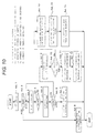
- FIG. 10 is a flowchart illustrating an example sequence of operations for binding.
- symbol A indicates the number of sheets instructed to be printed
- symbol X indicates the allowable binding number of sheets which may be adhesive bound by the adhesive binding unit 10 at one time
- symbol N indicates the predetermined remaining number of sheets set by the user in advance (in other words, the symbol N is a threshold value for determining whether or not A sheets are bound and discharged as one bundle)
- symbol R indicates the number of printed sheets received by the post-processing apparatus 1 from the image forming apparatus 7.
- the predetermined remaining number of sheets N may be set by the user in advance, through use of a control panel on the display (not shown) or through a remote terminal such as a PC (not shown).
- the predetermined remaining number of sheets N may have a default value set in advance.
- Act 1 the number A of sheets instructed to be printed is obtained from the image forming apparatus and the process proceeds to Act 2.
- the number A of sheets instructed to be printed and the allowable binding number (X) of sheets are compared. If A ⁇ X, since the height of the sheets of the number A of sheets instructed to be printed is that of the allowable binding number (X) of sheets or less, the height does not reach the binding limit height h. That is, since there is no hindrance to the adhesive binding in the adhesive binding unit 10, the process proceeds to Act 8. Meanwhile, if A>X, since there is a concern that the height of the sheets of the number A of sheets instructed to be printed exceeds the binding limit height h, the process proceeds to Act 3.
- each sheet is adhesive bound by transferring the adhesive to the sheet one by one.
- Act 4 the information of R of the number of sheets received by the post-processing apparatus 1 is compared to the allowable binding number (X) of sheets. If the number of sheets fed to the adhesive binding unit 10 reaches the allowable binding number (X) of sheets, the process proceeds to Act 5.
- the remaining number (n) of sheets still to be received by the post-processing apparatus is determined and the process proceeds to Act 6.
- the remaining number (n) of sheets is compared to the predetermined remaining number (N) of sheets set in advance. If n ⁇ N, the process proceeds to Act 7 and the first mode is executed. Meanwhile, if n>N, the process proceeds to Act 9 and the second mode or the third mode is executed. That is, since the height of the sheets according to the number (A) of sheets instructed to be printed, exceeds the binding limit height h, it is not possible to perform the adhesive binding by the adhesive binding unit 10.
- the determination of Act 6 may be made after the number (A) of sheets to be printed has been provided and before the adhesive binding process begins.
- Act 10 if the controller 50 receives a signal of a continuing process from the operation unit 56, in order to discharge the sheets by dividing into two bundles, in Act 11, the adhesive binding is performed for the number (X) of sheets as one bundle and the process proceeds to Act 12. Moreover, in the embodiment, the adhesive binding is performed for each sheet by transferring the adhesive to the sheet one by one.
- the adhesive binding is performed for the number (n) of sheets as a second bundle and the second sheet bundle is discharged to the second discharge tray 105 and the main process is completed.
- the binding is performed for the remaining (n) sheets in a post-process (for example, stapling) different from the adhesive binding and the main process is completed.
- a post-process for example, stapling
- the adhesive application is performed exceeding the allowable binding number (X) of sheets and the allowable binding number (X) of sheets and the remaining number (n) of sheets are discharged as the bundle of A sheets.
- the number of sheets received by the post-processing apparatus reaches the allowable binding number (X) of sheets of the adhesive binding unit 10 and the remaining number (n) of sheets exceeds the predetermined remaining number (N) of sheets, since the height of A sheets to be bound exceeds the binding limit height h, whether or not the adhesive application is continued is displayed on the operation unit and the user determines the continuation of the adhesive application.
- stop instead of continuation the user selects the binding of the remaining (n) the sheets from the sort, staple, and the like.
Landscapes
- Engineering & Computer Science (AREA)
- Mechanical Engineering (AREA)
- Textile Engineering (AREA)
- Folding Of Thin Sheet-Like Materials, Special Discharging Devices, And Others (AREA)
Abstract
Description
- Embodiments described herein relate generally to a technique for producing a sheet bundle by applying adhesive to sheets continuously fed one by one.
- In the related art, a sheet post-processing apparatus is provided in which sheets discharged from an image forming apparatus body are sequentially received, the sheets are discharged and stacked on a processing tray, and a sheet bundle is bound. Then, the sheet post-processing apparatus includes a adhesive application mechanism in which adhesive is applied to a portion corresponding to a predetermined binding margin of the sheet. An operation for loading the sheets on a adhesive application portion is sequentially repeated. A plurality of sheets are thereby produced in a bundle.
- However, the maximum number of sheets that can be bound at one time by the adhesive application mechanism is limited. Thus, there is a problem that it is not possible to set the sheets exceeding the predetermined number in the adhesive application mechanism.
-
-
FIG. 1 is a schematic illustration of a post-processing apparatus according to an embodiment. -
FIG. 2 is a perspective view illustrating an adhesive binding process unit viewed from a processing tray side. -
FIG. 3 is a perspective view illustrating the adhesive binding process unit with periphery members removed. -
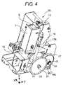
FIG. 4 is another perspective view illustrating the adhesive binding process unit. -
FIG. 5 is a front view illustrating the adhesive binding unit. -
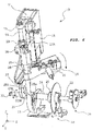
FIG. 6 is a perspective view illustrating a driving mechanism of the adhesive binding unit. -
FIG. 7 is a perspective view illustrating a shutter member of the adhesive binding unit. -
FIG. 8 is a schematic view illustrating another configuration of an adhesive applying unit. -
FIG. 9 is a block diagram of a control block of the post-processing apparatus. -
FIG. 10 is a flowchart illustrating an example sequence of operations for binding. - A post-processing apparatus according to an embodiment includes an adhesive binding unit that binds a plurality of sheets into a bundle. A controller sets an allowable binding number X of sheets capable of being subject to binding at one time in the adhesive binding apparatus. The controller sets a predetermined remaining number N of sheets. The controller receives a number A of the sheets instructed to be bound in the adhesive binding unit. The controller calculates a remaining number n of sheets, where n=A-X. The controller determines whether n>N or n≤N. The adhesive binding unit binds the A number of the sheets into a single bundle when it is determined that n<N.
- Preferably, the apparatus further comprises: a counter configured to count a number R of sheets currently conveyed to the post-processing apparatus from the image forming apparatus, wherein, when it is determined that n>N and when the number R of sheets counted by the counter is R=X, the controller controls the adhesive binding unit to bind only the first X number of sheets into a single bundle.
- Preferably, when it is determined that n>N, the controller is configured to control the adhesive binding unit to process the remaining number of sheets counted by the counter when R>X according to a processing indicated by a received user instruction.
- Preferably, the processing indicated by the received user instruction is selected from a display that displays a selectable first mode in which the remaining number of sheets counted by the counter when R>X is processed by binding as another single bundle in the adhesive binding unit and a selectable second mode in which the remaining number sheets counted by the counter when R>X is processed according to another processing that is not binding in the adhesive binding unit.
- Preferably, the apparatus further comprises: a second binding unit configured to perform a second binding process different from the adhesive binding performed in the adhesive binding unit.
- Preferably, when the second mode is selected, the controller controls the second binding unit to perform the second binding process.
- Preferably, the another processing is one of sorting and stapling.
- Preferably, the adhesive binding unit applies an adhesive tape between each of the plurality of sheets.
- Preferably, the adhesive binding unit applies a liquid adhesive between each of the plurality of sheets.
- Preferably, the apparatus further comprises a punching unit configured to punch at least one hole in each the plurality of sheets conveyed from the image forming apparatus.
- Preferably, the adhesive binding unit includes a pressing plate and a bottom plate configured to press the bundle therebetween.
- Preferably, N is set so that a number X+N of the sheets is the maximum number of sheets that can be bound in a single bundle by the adhesive binding unit based on a thickness of each sheet and a distance between the pressing plate and the bottom plate.
- The apparatus makes it possible to set the sheets exceeding the predetermined number in the adhesive application mechanism.
- The present invention further relates to a post-processing method comprising the steps of: receiving a number A of the sheets instructed to be bound in an adhesive binding unit that is configured to bind a plurality of sheets into a bundle by applying an adhesive between each of the plurality of sheets and thereafter pressing the bundle; setting an allowable binding number X of sheets capable of being subject to binding at one time in the adhesive binding apparatus; setting a predetermined remaining number N of sheets; calculating a remaining number n of sheets, where n=A-X; determining whether n>N or n≤N; and binding the number A of the sheets into a single bundle in the adhesive binding unit when it is determined that n<N.
- Preferably, the method further comprises the steps of: counting a number R of sheets currently conveyed to the post-processing apparatus from the image forming apparatus; and binding only the first X number of sheets into a single bundle when it is determined that n>N and when the number R of sheets counted is R=X.
- Preferably, when it is determined that n>N, the remaining number of sheets counted by the counter when R>X are processed according to a processing indicated by a received user instruction.
- Preferably, the processing indicated by the received user instruction is selected from a display that displays a selectable first mode in which the counted remaining number of sheets when R>X is processed by binding as another single bundle in the adhesive binding unit and a selectable second mode in which the remaining number sheets counted by the counter when R>X is processed according to another processing that is not binding in the adhesive binding unit.
- Preferably, the method further comprises the step of: performing, in a second binding unit, a second binding process different from the adhesive binding performed in the adhesive binding unit on the remaining number sheets counted for R>X when the second mode is selected.
- Preferably, the another processing is one of sorting and stapling.
- Preferably, the adhesive binding unit applies an adhesive tape between each of the plurality of sheets.
- Preferably, the adhesive binding unit applies a liquid adhesive between each of the plurality of sheets.
- Preferably, the method further comprises the step of: punching at least one hole in each the plurality of sheets conveyed from the image forming apparatus.
- Preferably, the adhesive binding unit includes a pressing plate and a bottomplate configured to press the bundle therebetween, and N is set so that a number X+N of the sheets is the maximum number of sheets that can be bound in a single bundle by the adhesive binding unit based on a thickness of each sheet and a distance between the pressing plate and the bottom plate.
- The method according to the present invention makes it possible to set the sheets exceeding the predetermined number in the adhesive application mechanism.
- Hereinafter, a sheet binding apparatus according to an embodiment and a post-processing apparatus (so-called finisher) including the sheet binding apparatus will be described in detail as non-limiting examples, with reference to the drawings.
-
FIG. 1 is a schematic view illustrating apost-processing apparatus 1. For example, thepost-processing apparatus 1 according to the embodiment receives a sheet discharged from animage forming apparatus 7 connected to thepost-processing apparatus 1. Thepost-processing apparatus 1 performs various processes such as binding, folding, and drilling with respect to the sheets.FIG. 2 is a perspective view illustrating an adhesive binding process unit viewed from a processing tray side andFIG. 3 is a perspective view illustrating the adhesive binding process with periphery members removed. - The
post-processing apparatus 1 includes, for example, a binding unit T, a folding unit B, a stapler W, apunching unit 109, and the like for performing post-processing functions. Here, as an example, the configuration of thepost-processing apparatus 1 includes the binding unit T, the folding unit B, the stapler W, thepunching unit 109, and the like. Thepost-processing apparatus 1 is not limited to the example, but includes at least the binding unit T. - First, the sheet on which an image is formed in the
image forming apparatus 7 passes through thepunching unit 109. When hole punching is to be performed with respect to the sheet, the hole punching is performed to the sheet by thepunching unit 109 at this time point. - A transporting destination of the sheet passed through the
punching unit 109 is switched to one of atransportation path 110 and atransportation path 108 by aflapper 117. - If only the hole punching is desired to be performed with respect to the sheet, or if the sheet passed through the
punching unit 109 is desired to be discharged to the outside of the apparatus without change, the sheet is guided to thetransportation path 108 by theflapper 117 and is further guided to atransportation path 119 by aflapper 107, and then is discharged to afirst discharge tray 106. - Meanwhile, if binding with respect to the sheet is desired to be performed by the binding unit T, the sheet guided to the
transportation path 108 is further guided to atransportation path 120 by theflapper 107 and is discharged on a temporary tray 104 (so-called buffer tray). - Thereafter, the sheet discharged on the
temporary tray 104 is knocked off by a rotatingpaddle 103 rotating counterclockwise on a paper surface ofFIG. 1 and is stacked on aprocessing tray 102. - The binding unit T includes a
adhesive application unit 101 that performs adhesive application on an upper surface of the sheet stacked on theprocessing tray 102. The binding unit T performs the adhesive application on the upper surface of the sheet with theadhesive application unit 101 whenever the sheet is stacked on theprocessing tray 102. However, for example, if a sheet bundle of 10 sheets being bound, adhesive application is not performed on an upper surface of the tenth sheet (the uppermost sheet stacked on the ninth sheet). - The
adhesive application unit 101 includes an adhesive applying unit U that is removably stored in aholder 11. A pressingforce receiving stand 12 is disposed below theholder 11. Theholder 11 is movably held in aguide shaft 13 and can move in an axial direction. When theholder 11 is positioned in a standby position to which theholder 11 moves upward from the pressingforce receiving stand 12 in the axial direction by a distance H, the distance H corresponds to the number of sheets that is bound at one time. In order to apply a pressing force after the adhesive application, apressing plate 14 is disposed between a lower end of theholder 11 and the uppermost surface of the sheet bundle stacked on the pressingforce receiving stand 12. Thus, the maximum height (maximum number of sheets) of the sheet bundle becomes a height (h) which is smaller than a height H, considering an arrangement space of thepressing plate 14 or the like. The binding number of sheets corresponding to the height (hereinafter, referred to as a binding limit height) h is the allowable binding number (X) of sheets. - However, the number of sheets corresponding to the binding limit height h is different depending on the thickness of the sheets. Furthermore, a thickness of the adhesive used for the adhesive binding is not necessarily constant. Thus, in the embodiment, the allowable binding number (X) of sheets corresponding to the binding limit height h is set to be a small number of sheets and the binding is performed with a certain degree of allowance.
- Thus, even if the binding number of sheets exceeds the allowable binding number (X) of sheets, the height thereof practically may be the binding limit height h or less, even with the exceeded number of sheets. Thus, the number of sheets in which the predetermined number (N) of sheets is added to the allowable binding number (X) of sheets practically corresponds to the binding limit height h. Thus, even if the number (A) of sheets instructed to be printed exceeds the allowable binding number (X) of sheets, when the exceeded number of sheets (the remaining number (n) of sheets described below) is smaller than the predetermined number (N) of sheets (predetermined remaining number of sheets), the sheets are bound as one bundle.
- Upper and
lower holder arms holder 11 are slidably inserted into theguide shaft 13 in the axial direction. Furthermore, first and secondpressing springs holder 11 and a adhesive application unit substrate (not illustrated), and function to bias theholder 11 towards the pressingforce receiving stand 12. - As illustrated in
FIG. 7 , thepressing plate 14 is formed with a concaved vertically cross-sectional shape in whichflanges 142 rise upward from three sides of a rectangular plate-shapedbottom plate 141. A lower end of theholder 11 abuts upper surfaces of theflanges 142 so that an adhesive applying surface of the adhesive applying unit U does not directly abut thebottom plate 141. - The adhesive applying unit U is the adhesive applying unit which causes the adhesive as adhesive for bonding the sheets each other to be applied to the sheet. Specifically, as the adhesive applying unit, it is possible to employ a system in which the adhesive is applied by abutting mesh impregnated with liquid adhesive and the like.
- An adhesive binding position of the sheet mounted on the
processing tray 102 is mounted on the pressingforce receiving stand 12 in a state of abutting an abutting alignment position. Thus, the adhesive applying unit U applies the adhesive to a predetermined region of the upper surface of the sheet when being pressed by the spring forces of the first and secondpressing springs - When the
holder 11 moves up and down for applying the adhesive, thepressing plate 14 is held in a position retracted from the pressingforce receiving stand 12. Thepressing plate 14 is mounted on a pressingplate holding body 18. The pressingplate holding body 18 is fixed torotation arms rotation arms guide shaft 13 and can move in the axial direction and rotatably about the shaft. Theupper holder arm 15 is disposed above theupper rotation arm 19. Theupper rotation arm 19 is disposed above thelower holder arm 16. Thelower rotation arm 20 is disposed below thelower holder arm 16. - Thus, the pressing
plate holding body 18 moves up and down following the up and down movement of theholder 11. Furthermore, thepressing plate 14 is capable of turning about theguide shaft 13 between a pressing position immediately above the pressingforce receiving stand 12 and a non-pressing position retracted from the pressingforce receiving stand 12. - A turning spring 21-which may be a tension spring, for example-is disposed between the pressing
plate holding body 18 and a adhesive application unit substrate (not illustrated), and biases thepressing plate 14 towards the non-pressing position. - A turning drive unit drives the
pressing plate 14 to be turned against the spring force of the turningspring 21. An up-down drive unit moves theholder 11 up and down against the spring forces of the first and secondpressing springs - In
FIGS. 4 to 6 , a motor gear MG is mounted on a motor shaft MS of the motor M. The motor gear MG is meshed with an intermediate gear GI. A first transmission gear G1 having a coaxial small diameter is mounted on the intermediate gear GI. The first transmission gear G1 is meshed with a second transmission gear G2 having a large diameter. The second transmission gear G2 is mounted on afirst rotation shaft 22. - The up-down drive unit includes a disk-shaped
first cam 23 fixed to thefirst rotation shaft 22. Asecond rotation shaft 24 is coaxially mounted on thefirst rotation shaft 22 from outside. The turning drive unit includes asecond cam 25 fixed to thesecond rotation shaft 24. - The
first rotation shaft 22 and thesecond rotation shaft 24 are connected through a one-way clutch 26. When thefirst rotation shaft 22 rotates counterclockwise (CCW), the one-way clutch 26 transmits a rotational force to thesecond rotation shaft 24 and integrally rotates thefirst rotation shaft 22 and thesecond rotation shaft 24 counterclockwise. Meanwhile, when thefirst rotation shaft 22 rotates clockwise (CW), the one-way clutch 26 does not transmit the rotational force to thesecond rotation shaft 24 and only rotates thefirst rotation shaft 22 clockwise. - A plate-shaped
lifting cam follower 27 abuts a cam surface of thefirst cam 23 and is mounted on a lower portion of theholder 11. A rod-shapedturning cam follower 28 engages the cam surface of thesecond cam 25 and is passed through and fixed to base sides of therotation arms - In the embodiment, when the
holder 11 moves up and down and thepressing plate 14 is held in the non-pressing position (illustrated inFIG. 6 ) to perform the adhesive application, the motor M is controlled so that thefirst rotation shaft 22 rotates clockwise. When pressing the sheet bundle to which the adhesive application is performed, the motor M is controlled so that thefirst rotation shaft 22 rotates counterclockwise. - A cam top position (corresponding to the retracted position of the holder 11) of the
first cam 23 is detected by a firstphase sensor unit 29 provided in a leading end portion of thefirst rotation shaft 22. An engagement start position (corresponding to the non-pressing position) of thesecond cam 25 with the turningcam follower 28 is detected by a secondphase sensor unit 30 provided in a leading end portion of thesecond rotation shaft 24. - For example, the
first cam 23 may be configured with a true circular-shaped disk mounted on and eccentric relative to thefirst rotation shaft 22. In the state illustrated inFIG. 6 , theholder 11 is held in a standby position and the firstphase sensor unit 29 outputs an ON signal indicating the standby position. When thefirst rotation shaft 22 starts to rotate, the output of the firstphase sensor unit 29 is switched to OFF and when thefirst rotation shaft 22 rotates one round, the output is switched to the ON signal. - In the
second cam 25, a cut-outportion 25a is formed in a part of a substantially disk-shaped member. The state illustrated inFIG. 6 indicates the non-pressing position in which the rod-shapedturning cam follower 28 is fitted into the cut-outportion 25a and is engaged with one end surface of the cut-outportion 25a. Anextension portion 25b extending to thefirst cam 23 side is formed in one end surface of the cut-outportion 25a. When thesecond cam 25 rotates counterclockwise from the state illustrated inFIG. 6 , the turningcam follower 28 starts to turn about theguide shaft 13 clockwise while engaging with one end of the cut-outportion 25a. At the same time, the turningcam follower 28 moves downward while following downward moving of theholder 11. When thesecond cam 25 further rotates clockwise, the turningcam follower 28 is switched to the engagement with theextension portion 25b and thepressing plate 14 reaches the pressing position. When thepressing plate 14 reaches the pressing position, the turningcam follower 28 is released from the engagement with thesecond cam 25. - In the engagement released state, the
pressing plate 14 receives the spring force of the turningspring 21. However, thepressing plate 14 is interposed between the lower end of theholder 11 and the upper surface of the sheet bundle. After thefirst rotation shaft 22 rotates half-way around, theholder 11 starts to move upward against the spring forces of the first and secondpressing springs pressing plate 14 starts to turn counterclockwise. Furthermore, the turningcam follower 28 is fitted into the cut-outportion 25a of thesecond cam 25 while rising with the start of turning. Then, when thefirst rotation shaft 22 rotates counterclockwise all the way around, the pressing operation is completed. - As described above, the adhesive application is completed with respect to each of the sheets other than the uppermost sheet in a plurality of sheets mounted on the
processing tray 102, which are the target of the binding. Then, the plurality of sheets are pressed toward thepressing plate 14 by the binding unit T in a state where the entirety of the plurality of sheets configuring the sheet bundle are overlapped and mounted. Here, after theadhesive application unit 101 applies the adhesive on the sheet, a portion between the adjacent sheets in the plurality of sheets is firmly adhered (crimped) by the adhesive by pressing of a pressing mechanism, and the sheet binding is completed. - As illustrated in
FIG. 8 , in the adhesive applying unit U, an adhesive tape method may be also applied. - In the adhesive applying unit U in
FIG. 8 , a pressure-sensitive transfer type adhesive tape (hereinafter, abbreviated as an adhesive tape) 141 is used as the adhesive. Theadhesive tape 141 is wound on afeeding reel 142 in a roll shape and one end thereof is wound on a windingreel 143. Anadhesive base material 145 of theadhesive tape 141 is peelably adhered to one surface of aroll film 144 through an adhesive layer. Thebase material 145 has a double face adhesive property and is peeled from theadhesive tape 141 in a transfer region transferred to an adhered surface. - The feeding
reel 142 and the windingreel 143 are rotatably supported by asubstrate 146. Theadhesive tape 141 also extends aroundrollers substrate 146. A length between theroller 147 and theroller 148 is a pressing transfer region T. Thesubstrate 146 is pressed down in anarrow direction 200. Thebase material 145 of theadhesive tape 141 is pressed on a transferredsurface 201. Then thesubstrate 146 is returned upward, whereby thebase material 145 of the pressing transfer region T is transferred to the transferredsurface 201. - In the embodiment, the
substrate 146 is disposed in anouter case 203 movably in the up-down direction. Aspring member 204 biases thesubstrate 146 downward in the drawing with respect to theouter case 203. A first gear G11 is coaxially fixed to the windingreel 143 and a second gear G12 is coaxially fixed to thefeeding reel 142. The first gear G11 and the second gear G12 are meshed with each other. Thus, when theadhesive tape 141 is drawn in a winding direction, the first gear G11 rotates counterclockwise, the windingreel 143 rotates clockwise together with the second gear G12, and theadhesive tape 141 is wound on the windingreel 143. - A third gear G13 is mounted on the winding
reel 143 coaxially with the second gear G12 through a one-way clutch mechanism (not illustrated). A rack gear G14 is mounted on the inside of acase 203. The third gear G13 is meshed with the rack gear G14. - When the third gear G13 rotates clockwise, the one-way clutch connects the third gear G13 and the winding
reel 143, and the windingreel 143 winds theadhesive tape 141 by the rotational force of the third gear G13. - Conversely, when the winding
reel 143 rotates clockwise, the one-way clutch releases the connection of the third gear G13 and the windingreel 143, and only the windingreel 143 rotates in the winding direction. - When the
substrate 146 is pressed downward by the spring force of thespring member 204 with respect to theouter case 203, the third gear G13 rotates clockwise by meshing with the rack gear G14 and winds theadhesive tape 141 onto the windingreel 143. That is, after thebase material 145 is transferred, when moving theouter case 203 upward, theadhesive tape 141 is wound onto the windingreel 143 at a predetermined amount and thebase material 145 is positioned in the pressing transfer region T in synchronization with thesubstrate 146 being pressed downward by the spring force of thespring member 204. - Meanwhile, if folding or stapling is desired to be performed with respect to the sheet passed through the
punching unit 109, the sheet is guided to thetransportation path 110 by theflapper 117 and the stapling by the stapler W or the folding by the folding unit B is performed with respect to the sheet discharged on astacker 111. Specifically, for example, the folding unit B folds the sheet bundle, in which the stapling is performed by the stapler W, with afolding blade 112 and afolding roller 113. A fold mark is further sandwiched by a folding-enhancingroller 114 and then the folded sheet bundle is discharged on athird discharge tray 116 by a dischargingroller 115. - Thereafter, for example, the sheet bundle formed of the plurality of sheets which are bound by the binding is discharged on a
second discharge tray 105 by a discharge member (not illustrated) provided in theprocessing tray 102. - Next, if the total number of sheets to be printed exceeds the allowable binding number (X) of sheets in the
adhesive application unit 10, it is not possible to perform appropriate adhesive application. Furthermore, there is a concern that remaining sheet exceeding the allowable binding number of sheets causes paper jam on the processing tray. - In the embodiment, the number of sheets fed to the
processing tray 102 may be obtained by asheet detection sensor 8 provided on a sheet discharge side of theimage forming apparatus 7. Alternatively, the total number of sheets to be printed may be obtained by theimage forming apparatus 7. - Thus, in the embodiment, if a number of remaining sheets exceeding the allowable binding number (X) of sheets are present, according to whether or not the remaining number (n) of sheets exceeds the predetermined value (N), a first mode in which the adhesive binding is performed also including the remaining sheets as a bundle and a second mode in which a user selects whether or not the adhesive application is continued. If the adhesive application is continued, the adhesive binding is performed for the remaining sheets as another sheet bundle are provided. Furthermore, if the user selects that the adhesive application is not continued, a third mode in which the adhesive binding is performed for (X) sheets as one bundle and the binding is performed for the remaining (n) sheets in a post-process different from the adhesive binding such as sorting and stapling is provided.
-
FIG. 9 is a block diagram of a control block of the post-processing apparatus. - In
FIG. 9 , acontroller 50, adisplay unit 55, anoperation unit 56, a adhesive bindingunit 57, the stapler W, asorter 58, a printnumber instruction unit 59, thesheet discharge sensor 8, and the like are connected through abus 60. - The
controller 50 has aprocessor 51, which may be a Central Processing Unit (CPU) or a Micro Processing Unit (MPU), and amemory 52. - The
processor 51 determines the remaining number n of sheets based on the number A of sheets instructed to be printed from the printnumber instruction unit 59 and the allowable binding number X of sheets from the bindingunit 10. Theprocessor 51 executes the first mode by comparing the remaining number n of sheets to the predetermined remaining number N of sheets. Furthermore, theprocessor 51 executes the second mode and the third mode based on operation information from the user operating theoperation unit 56. - For example, the
memory 52 is a semiconductor memory and has a Read Only Memory (ROM) 53 for storing various control programs and a Random Access Memory (RAM) 54 for supplying a temporal working area in theprocessor 51. For example, theROM 53 stores a program determining the remaining number n of sheets based on the number A of sheets instructed to be printed and the allowable binding number X of sheets, a program executing the first mode by comparing the remaining number n of sheets to the predetermined remaining number N of sheets, and a program executing the second mode and the third mode based on the operation information of whether theoperation unit 56 is continued or stopped. -
FIG. 10 is a flowchart illustrating an example sequence of operations for binding. - In
FIG. 10 , symbol A indicates the number of sheets instructed to be printed, symbol X indicates the allowable binding number of sheets which may be adhesive bound by the adhesive bindingunit 10 at one time, symbol N indicates the predetermined remaining number of sheets set by the user in advance (in other words, the symbol N is a threshold value for determining whether or not A sheets are bound and discharged as one bundle), symbol n (n=A-X) indicates the remaining number of sheets exceeding the allowable binding number (X) of sheets, and symbol R indicates the number of printed sheets received by thepost-processing apparatus 1 from theimage forming apparatus 7. As noted, the predetermined remaining number of sheets N may be set by the user in advance, through use of a control panel on the display (not shown) or through a remote terminal such as a PC (not shown). The predetermined remaining number of sheets N may have a default value set in advance. - In
Act 1, the number A of sheets instructed to be printed is obtained from the image forming apparatus and the process proceeds toAct 2. - In
Act 2, the number A of sheets instructed to be printed and the allowable binding number (X) of sheets are compared. If A≤X, since the height of the sheets of the number A of sheets instructed to be printed is that of the allowable binding number (X) of sheets or less, the height does not reach the binding limit height h. That is, since there is no hindrance to the adhesive binding in the adhesive bindingunit 10, the process proceeds toAct 8. Meanwhile, if A>X, since there is a concern that the height of the sheets of the number A of sheets instructed to be printed exceeds the binding limit height h, the process proceeds toAct 3. - In
Act 8, the adhesive binding is performed for A sheets as one bundle and a main process is completed. Moreover, in the adhesive binding of the embodiment, each sheet is adhesive bound by transferring the adhesive to the sheet one by one. - In
Act 3, the information of R of the number of sheets received from theimage forming apparatus 7 detected by thesheet discharge sensor 8 is counted and the process proceeds toAct 4. - In
Act 4, the information of R of the number of sheets received by thepost-processing apparatus 1 is compared to the allowable binding number (X) of sheets. If the number of sheets fed to the adhesive bindingunit 10 reaches the allowable binding number (X) of sheets, the process proceeds toAct 5. - In
Act 5, thereafter, the remaining number (n) of sheets still to be received by the post-processing apparatus is determined and the process proceeds toAct 6. Here, the remaining number (n) of sheets is determined by the following expression n=A-X (or n=A-R). - In
Act 6, the remaining number (n) of sheets is compared to the predetermined remaining number (N) of sheets set in advance. If n≤N, the process proceeds to Act 7 and the first mode is executed. Meanwhile, if n>N, the process proceeds to Act 9 and the second mode or the third mode is executed. That is, since the height of the sheets according to the number (A) of sheets instructed to be printed, exceeds the binding limit height h, it is not possible to perform the adhesive binding by the adhesive bindingunit 10. The determination ofAct 6 may be made after the number (A) of sheets to be printed has been provided and before the adhesive binding process begins. - In
Act 7, since the remaining number (n) of sheets is less than N, the adhesive binding is performed for the number A of sheets instructed to be printed as one bundle and the sheets are discharged, the main process is completed. That is, even if the height of the sheets to be adhesive bound exceeds that of the allowable binding number (X) of sheets, since the height of the sheets to be adhesive bound does not reach the binding limit height h, the adhesive binding is performed as one bundle. - In
Act 9, display of effect to continue is performed in thedisplay unit 55 and the process proceeds to Act 10. - In
Act 10, if thecontroller 50 receives a signal of a continuing process from theoperation unit 56, in order to discharge the sheets by dividing into two bundles, inAct 11, the adhesive binding is performed for the number (X) of sheets as one bundle and the process proceeds to Act 12. Moreover, in the embodiment, the adhesive binding is performed for each sheet by transferring the adhesive to the sheet one by one. - In
Act 12, the adhesive binding is performed for the number (n) of sheets as a second bundle and the second sheet bundle is discharged to thesecond discharge tray 105 and the main process is completed. - In
Act 10, if thecontroller 50 receives a signal of process stop from theoperation unit 56, the process proceeds to Act 13 and the third mode is executed. - In
Act 13, the adhesive binding is performed for X sheets as one bundle, and the bundle of X sheets is discharged in a binding state. The process then proceeds to Act 14. - In
Act 14, the remaining (n) sheets are discharged in a state being not bound respectively and the process proceeds to Act 15. - In
Act 15, the binding is performed for the remaining (n) sheets in a post-process (for example, stapling) different from the adhesive binding and the main process is completed. - As described above, if the number of sheets discharged from the
image forming apparatus 7 and received by the post-processing apparatus reaches the allowable binding number (X) of sheets of the adhesive bindingunit 10 and the remaining number (n) of sheets is the predetermined remaining number (N) of sheets or less, since the height of A sheets to be bound is the binding limit height h or less, the adhesive application is performed exceeding the allowable binding number (X) of sheets and the allowable binding number (X) of sheets and the remaining number (n) of sheets are discharged as the bundle of A sheets. - Meanwhile, if the number of sheets received by the post-processing apparatus reaches the allowable binding number (X) of sheets of the adhesive binding
unit 10 and the remaining number (n) of sheets exceeds the predetermined remaining number (N) of sheets, since the height of A sheets to be bound exceeds the binding limit height h, whether or not the adhesive application is continued is displayed on the operation unit and the user determines the continuation of the adhesive application. - If stop instead of continuation is determined, the user selects the binding of the remaining (n) the sheets from the sort, staple, and the like.
- While certain embodiments have been described, these embodiments have been presented by way of example only, and are not intended to limit the scope of the exemplary embodiment. Indeed, the novel embodiments described herein may be embodied in a variety of other forms; furthermore, various omissions, substitutions and changes in the form of the embodiments described herein may be made without departing from the framework of the exemplary embodiment. The accompanying claims and their equivalents are intended to cover such forms or modifications as would fall within the scope of the exemplary embodiment.
Claims (15)
- A post-processing apparatus comprising:an adhesive binding unit configured to bind a plurality of sheets into a bundle by applying an adhesive between each of the plurality of sheets and thereafter pressing the bundle, each of the plurality of sheets being conveyed from an image forming apparatus; anda controller configured to:set an allowable binding number X of sheets capable of being subject to binding at one time in the adhesive binding apparatus;set a predetermined remaining number N of sheets;receive a number A of the sheets instructed to be bound in the adhesive binding unit;calculate a remaining number n of sheets, where n=A-X;determine whether n>N or n≤N; andcontrol the adhesive binding unit to bind the number A of the sheets into a single bundle when it is determined that n<N.
- The apparatus according to claim 1, further comprising:a counter configured to count a number R of sheets currently conveyed to the post-processing apparatus from the image forming apparatus,wherein, when it is determined that n>N and when the number R of sheets counted by the counter is R=X, the controller controls the adhesive binding unit to bind only the first X number of sheets into a single bundle.
- The apparatus according to claim 2, wherein, when it is determined that n>N, the controller is configured to control the adhesive binding unit to process the remaining number of sheets counted by the counter when R>X according to a processing indicated by a received user instruction.
- The apparatus according to claim 3, wherein the processing indicated by the received user instruction is selected from a display that displays a selectable first mode in which the remaining number of sheets counted by the counter when R>X is processed by binding as another single bundle in the adhesive binding unit and a selectable second mode in which the remaining number sheets counted by the counter when R>X is processed according to another processing that is not binding in the adhesive binding unit.
- The apparatus according to claim 4, further comprising:a second binding unit configured to perform a second binding process different from the adhesive binding performed in the adhesive binding unit,wherein, when the second mode is selected, the controller controls the second binding unit to perform the second binding process.
- The apparatus according to claim 4 or 5, wherein the another processing is one of sorting and stapling.
- The apparatus according to any one of claims 1 to 6, wherein the adhesive binding unit applies an adhesive tape between each of the plurality of sheets.
- The apparatus according to any one of claims 1 to 7, wherein the adhesive binding unit applies a liquid adhesive between each of the plurality of sheets.
- The apparatus according to any one of claims 1 to 8, further comprising a punching unit configured to punch at least one hole in each the plurality of sheets conveyed from the image forming apparatus.
- The apparatus according to any one of claims 1 to 9, wherein
the adhesive binding unit includes a pressing plate and a bottom plate configured to press the bundle therebetween, and
N is set so that a number X+N of the sheets is the maximum number of sheets that can be bound in a single bundle by the adhesive binding unit based on a thickness of each sheet and a distance between the pressing plate and the bottom plate. - A post-processing method comprising the steps of:receiving a number A of the sheets instructed to be bound in an adhesive binding unit that is configured to bind a plurality of sheets into a bundle by applying an adhesive between each of the plurality of sheets and thereafter pressing the bundle;setting an allowable binding number X of sheets capable of being subject to binding at one time in the adhesive binding apparatus;setting a predetermined remaining number N of sheets;calculating a remaining number n of sheets, where n=A-X;determining whether n>N or n≤N; andbinding the number A of the sheets into a single bundle in the adhesive binding unit when it is determined that n≤N.
- The method according to claim 11, further comprising the steps of:counting a number R of sheets currently conveyed to the post-processing apparatus from the image forming apparatus; andbinding only the first X number of sheets into a single bundle when it is determined that n>N and when the number R of sheets counted is R=X.
- The method according to claim 12, wherein, when it is determined that n>N, the remaining number of sheets counted by the counter when R>X are processed according to a processing indicated by a received user instruction.
- The method according to claim 13, wherein the processing indicated by the received user instruction is selected from a display that displays a selectable first mode in which the counted remaining number of sheets when R>X is processed by binding as another single bundle in the adhesive binding unit and a selectable second mode in which the remaining number sheets counted by the counter when R>X is processed according to another processing that is not binding in the adhesive binding unit.
- The method according to claim 14, further comprising the step of:performing, in a second binding unit, a second binding process different from the adhesive binding performed in the adhesive binding unit on the remaining number sheets counted for R>X when the second mode is selected.
Applications Claiming Priority (1)
| Application Number | Priority Date | Filing Date | Title |
|---|---|---|---|
| US14/687,782 US9713933B2 (en) | 2015-04-15 | 2015-04-15 | Sheet post-processing apparatus |
Publications (2)
| Publication Number | Publication Date |
|---|---|
| EP3081386A1 true EP3081386A1 (en) | 2016-10-19 |
| EP3081386B1 EP3081386B1 (en) | 2018-04-11 |
Family
ID=56087068
Family Applications (1)
| Application Number | Title | Priority Date | Filing Date |
|---|---|---|---|
| EP16164703.7A Active EP3081386B1 (en) | 2015-04-15 | 2016-04-11 | Sheet post-processing apparatus |
Country Status (3)
| Country | Link |
|---|---|
| US (1) | US9713933B2 (en) |
| EP (1) | EP3081386B1 (en) |
| CN (1) | CN106042706B (en) |
Families Citing this family (6)
| Publication number | Priority date | Publication date | Assignee | Title |
|---|---|---|---|---|
| JP6320221B2 (en) * | 2014-07-29 | 2018-05-09 | 株式会社東芝 | Sheet binding device |
| US9724954B2 (en) | 2015-03-27 | 2017-08-08 | Kabushiki Kaisha Toshiba | Sheet pasting and binding apparatus and sheet post-processing apparatus |
| JP6548504B2 (en) * | 2015-08-04 | 2019-07-24 | キヤノン株式会社 | Sheet processing method, sheet processing apparatus and image forming apparatus |
| JP6800746B2 (en) * | 2016-12-28 | 2020-12-16 | キヤノン株式会社 | Image forming apparatus, control method of image forming apparatus, and program |
| CN115339255B (en) * | 2022-06-25 | 2024-04-23 | 得力集团有限公司 | Bookbinding machine and control method thereof |
| JP2024145770A (en) * | 2023-03-31 | 2024-10-15 | キヤノン株式会社 | PRINTING SYSTEM, PRINTING SYSTEM CONTROL METHOD, AND PROGRAM - Patent application |
Citations (3)
| Publication number | Priority date | Publication date | Assignee | Title |
|---|---|---|---|---|
| US20060103065A1 (en) * | 2004-11-16 | 2006-05-18 | Kyocera Mita Corporation | Sheet post-processing apparatus |
| US20110304090A1 (en) * | 2010-06-09 | 2011-12-15 | Fuji Xerox Co., Ltd. | Sheet processing apparatus, image forming system, and sheet processing method |
| US20150023765A1 (en) * | 2013-07-22 | 2015-01-22 | Canon Kabushiki Kaisha | Sheet processing apparatus and image forming apparatus |
Family Cites Families (12)
| Publication number | Priority date | Publication date | Assignee | Title |
|---|---|---|---|---|
| US5320335A (en) * | 1987-08-07 | 1994-06-14 | Canon Kabushiki Kaisha | Control method for sheet discharger with stapler method of stapling a group a discharged sheets into sub-groups having up to n sheets |
| US6188868B1 (en) * | 2000-02-18 | 2001-02-13 | Toshiba Tec Kabushiki Kaisha | Image forming apparatus |
| CN100432848C (en) * | 2004-04-05 | 2008-11-12 | 佳能株式会社 | Image forming system, control method, recording medium, and program |
| JP3814626B2 (en) * | 2004-04-05 | 2006-08-30 | キヤノン株式会社 | Image forming system, control method, storage medium, program, and image forming apparatus |
| JP4328685B2 (en) * | 2004-07-20 | 2009-09-09 | キヤノン株式会社 | Sheet processing device |
| JP4513694B2 (en) * | 2005-08-26 | 2010-07-28 | コニカミノルタビジネステクノロジーズ株式会社 | Image forming system |
| JP4218763B2 (en) * | 2006-01-27 | 2009-02-04 | 京セラミタ株式会社 | Image forming apparatus, post-processing apparatus, and image forming system including these |
| US7931262B2 (en) * | 2006-01-27 | 2011-04-26 | Kyoceramita Corporation | Image forming system including finisher with stapler for binding printed papers |
| JP2009202485A (en) | 2008-02-28 | 2009-09-10 | Duplo Corp | Pasting device |
| JP5550852B2 (en) * | 2009-05-26 | 2014-07-16 | コニカミノルタ株式会社 | Paper processing device |
| JP6039249B2 (en) * | 2012-06-07 | 2016-12-07 | キヤノン株式会社 | Sheet processing apparatus, sheet processing apparatus control method, and program |
| JP6227478B2 (en) * | 2013-08-30 | 2017-11-08 | 株式会社東芝 | Sheet binding apparatus, sheet binding method, and sheet post-processing apparatus |
-
2015
- 2015-04-15 US US14/687,782 patent/US9713933B2/en active Active
-
2016
- 2016-04-11 EP EP16164703.7A patent/EP3081386B1/en active Active
- 2016-04-12 CN CN201610225669.XA patent/CN106042706B/en not_active Expired - Fee Related
Patent Citations (3)
| Publication number | Priority date | Publication date | Assignee | Title |
|---|---|---|---|---|
| US20060103065A1 (en) * | 2004-11-16 | 2006-05-18 | Kyocera Mita Corporation | Sheet post-processing apparatus |
| US20110304090A1 (en) * | 2010-06-09 | 2011-12-15 | Fuji Xerox Co., Ltd. | Sheet processing apparatus, image forming system, and sheet processing method |
| US20150023765A1 (en) * | 2013-07-22 | 2015-01-22 | Canon Kabushiki Kaisha | Sheet processing apparatus and image forming apparatus |
Also Published As
| Publication number | Publication date |
|---|---|
| CN106042706A (en) | 2016-10-26 |
| US9713933B2 (en) | 2017-07-25 |
| US20160303886A1 (en) | 2016-10-20 |
| EP3081386B1 (en) | 2018-04-11 |
| CN106042706B (en) | 2017-12-22 |
Similar Documents
| Publication | Publication Date | Title |
|---|---|---|
| EP3081386B1 (en) | Sheet post-processing apparatus | |
| JP4880575B2 (en) | Paper post-processing device | |
| CN104418151B (en) | Sheet binding device, sheet binding method, sheet post-processing device | |
| US8702087B2 (en) | Sheet handling apparatus, image forming system, and sheet reception control method | |
| CN108529269B (en) | Sheet processing apparatus and image forming apparatus including the same | |
| US8523165B2 (en) | Recording media sheet processing system, image forming system including same, and insertion method used therein | |
| US11198583B2 (en) | Sheet discharge device, and image forming system | |
| JP6704619B2 (en) | Sheet ejection device, image forming system and sheet post-processing device | |
| US8844919B2 (en) | Square back processing with variable nipping | |
| US20140062003A1 (en) | Sheet processing apparatus, method for using the same image and image forming system | |
| CN106315291B (en) | Sheet post processing apparatus and thin slice post-processing approach | |
| US9284152B2 (en) | Post-processing device and image forming apparatus | |
| US10668713B2 (en) | Sheet processing apparatus that applies an adhesive for binding sheets | |
| US9981498B2 (en) | Sheet pasting and binding apparatus and sheet post-processing apparatus | |
| US7497427B2 (en) | Image forming apparatus | |
| JP4577887B2 (en) | Collating device | |
| JP6879488B2 (en) | Sheet processing device and image forming device equipped with this | |
| US10052857B2 (en) | Sheet processing apparatus that applies an adhesive for binding sheets | |
| EP2979892B1 (en) | Sheet binding device | |
| JP7451960B2 (en) | Sheet binding device, image forming device | |
| JP2010285272A (en) | Image forming system and postprocessing device |
Legal Events
| Date | Code | Title | Description |
|---|---|---|---|
| PUAI | Public reference made under article 153(3) epc to a published international application that has entered the european phase |
Free format text: ORIGINAL CODE: 0009012 |
|
| AK | Designated contracting states |
Kind code of ref document: A1 Designated state(s): AL AT BE BG CH CY CZ DE DK EE ES FI FR GB GR HR HU IE IS IT LI LT LU LV MC MK MT NL NO PL PT RO RS SE SI SK SM TR |
|
| AX | Request for extension of the european patent |
Extension state: BA ME |
|
| STAA | Information on the status of an ep patent application or granted ep patent |
Free format text: STATUS: REQUEST FOR EXAMINATION WAS MADE |
|
| 17P | Request for examination filed |
Effective date: 20170419 |
|
| RBV | Designated contracting states (corrected) |
Designated state(s): AL AT BE BG CH CY CZ DE DK EE ES FI FR GB GR HR HU IE IS IT LI LT LU LV MC MK MT NL NO PL PT RO RS SE SI SK SM TR |
|
| RIC1 | Information provided on ipc code assigned before grant |
Ipc: B65H 37/02 20060101ALI20170828BHEP Ipc: B65H 43/00 20060101ALI20170828BHEP Ipc: B42C 1/12 20060101AFI20170828BHEP Ipc: B42C 19/02 20060101ALI20170828BHEP Ipc: B42C 9/00 20060101ALI20170828BHEP Ipc: B65H 37/04 20060101ALI20170828BHEP |
|
| GRAP | Despatch of communication of intention to grant a patent |
Free format text: ORIGINAL CODE: EPIDOSNIGR1 |
|
| STAA | Information on the status of an ep patent application or granted ep patent |
Free format text: STATUS: GRANT OF PATENT IS INTENDED |
|
| INTG | Intention to grant announced |
Effective date: 20171108 |
|
| GRAS | Grant fee paid |
Free format text: ORIGINAL CODE: EPIDOSNIGR3 |
|
| GRAA | (expected) grant |
Free format text: ORIGINAL CODE: 0009210 |
|
| STAA | Information on the status of an ep patent application or granted ep patent |
Free format text: STATUS: THE PATENT HAS BEEN GRANTED |
|
| AK | Designated contracting states |
Kind code of ref document: B1 Designated state(s): AL AT BE BG CH CY CZ DE DK EE ES FI FR GB GR HR HU IE IS IT LI LT LU LV MC MK MT NL NO PL PT RO RS SE SI SK SM TR |
|
| REG | Reference to a national code |
Ref country code: GB Ref legal event code: FG4D |
|
| REG | Reference to a national code |
Ref country code: CH Ref legal event code: EP |
|
| REG | Reference to a national code |
Ref country code: AT Ref legal event code: REF Ref document number: 987596 Country of ref document: AT Kind code of ref document: T Effective date: 20180415 |
|
| REG | Reference to a national code |
Ref country code: FR Ref legal event code: PLFP Year of fee payment: 3 |
|
| REG | Reference to a national code |
Ref country code: IE Ref legal event code: FG4D |
|
| REG | Reference to a national code |
Ref country code: DE Ref legal event code: R096 Ref document number: 602016002297 Country of ref document: DE |
|
| REG | Reference to a national code |
Ref country code: NL Ref legal event code: MP Effective date: 20180411 |
|
| REG | Reference to a national code |
Ref country code: LT Ref legal event code: MG4D |
|
| PG25 | Lapsed in a contracting state [announced via postgrant information from national office to epo] |
Ref country code: NL Free format text: LAPSE BECAUSE OF FAILURE TO SUBMIT A TRANSLATION OF THE DESCRIPTION OR TO PAY THE FEE WITHIN THE PRESCRIBED TIME-LIMIT Effective date: 20180411 |
|
| PG25 | Lapsed in a contracting state [announced via postgrant information from national office to epo] |
Ref country code: NO Free format text: LAPSE BECAUSE OF FAILURE TO SUBMIT A TRANSLATION OF THE DESCRIPTION OR TO PAY THE FEE WITHIN THE PRESCRIBED TIME-LIMIT Effective date: 20180711 Ref country code: AL Free format text: LAPSE BECAUSE OF FAILURE TO SUBMIT A TRANSLATION OF THE DESCRIPTION OR TO PAY THE FEE WITHIN THE PRESCRIBED TIME-LIMIT Effective date: 20180411 Ref country code: BG Free format text: LAPSE BECAUSE OF FAILURE TO SUBMIT A TRANSLATION OF THE DESCRIPTION OR TO PAY THE FEE WITHIN THE PRESCRIBED TIME-LIMIT Effective date: 20180711 Ref country code: FI Free format text: LAPSE BECAUSE OF FAILURE TO SUBMIT A TRANSLATION OF THE DESCRIPTION OR TO PAY THE FEE WITHIN THE PRESCRIBED TIME-LIMIT Effective date: 20180411 Ref country code: PL Free format text: LAPSE BECAUSE OF FAILURE TO SUBMIT A TRANSLATION OF THE DESCRIPTION OR TO PAY THE FEE WITHIN THE PRESCRIBED TIME-LIMIT Effective date: 20180411 Ref country code: SE Free format text: LAPSE BECAUSE OF FAILURE TO SUBMIT A TRANSLATION OF THE DESCRIPTION OR TO PAY THE FEE WITHIN THE PRESCRIBED TIME-LIMIT Effective date: 20180411 Ref country code: ES Free format text: LAPSE BECAUSE OF FAILURE TO SUBMIT A TRANSLATION OF THE DESCRIPTION OR TO PAY THE FEE WITHIN THE PRESCRIBED TIME-LIMIT Effective date: 20180411 Ref country code: LT Free format text: LAPSE BECAUSE OF FAILURE TO SUBMIT A TRANSLATION OF THE DESCRIPTION OR TO PAY THE FEE WITHIN THE PRESCRIBED TIME-LIMIT Effective date: 20180411 |
|
| PG25 | Lapsed in a contracting state [announced via postgrant information from national office to epo] |
Ref country code: HR Free format text: LAPSE BECAUSE OF FAILURE TO SUBMIT A TRANSLATION OF THE DESCRIPTION OR TO PAY THE FEE WITHIN THE PRESCRIBED TIME-LIMIT Effective date: 20180411 Ref country code: GR Free format text: LAPSE BECAUSE OF FAILURE TO SUBMIT A TRANSLATION OF THE DESCRIPTION OR TO PAY THE FEE WITHIN THE PRESCRIBED TIME-LIMIT Effective date: 20180712 Ref country code: LV Free format text: LAPSE BECAUSE OF FAILURE TO SUBMIT A TRANSLATION OF THE DESCRIPTION OR TO PAY THE FEE WITHIN THE PRESCRIBED TIME-LIMIT Effective date: 20180411 Ref country code: RS Free format text: LAPSE BECAUSE OF FAILURE TO SUBMIT A TRANSLATION OF THE DESCRIPTION OR TO PAY THE FEE WITHIN THE PRESCRIBED TIME-LIMIT Effective date: 20180411 |
|
| REG | Reference to a national code |
Ref country code: AT Ref legal event code: MK05 Ref document number: 987596 Country of ref document: AT Kind code of ref document: T Effective date: 20180411 |
|
| REG | Reference to a national code |
Ref country code: BE Ref legal event code: MM Effective date: 20180430 |
|
| PG25 | Lapsed in a contracting state [announced via postgrant information from national office to epo] |
Ref country code: PT Free format text: LAPSE BECAUSE OF FAILURE TO SUBMIT A TRANSLATION OF THE DESCRIPTION OR TO PAY THE FEE WITHIN THE PRESCRIBED TIME-LIMIT Effective date: 20180813 |
|
| REG | Reference to a national code |
Ref country code: DE Ref legal event code: R097 Ref document number: 602016002297 Country of ref document: DE |
|
| REG | Reference to a national code |
Ref country code: IE Ref legal event code: MM4A |
|
| PG25 | Lapsed in a contracting state [announced via postgrant information from national office to epo] |
Ref country code: CZ Free format text: LAPSE BECAUSE OF FAILURE TO SUBMIT A TRANSLATION OF THE DESCRIPTION OR TO PAY THE FEE WITHIN THE PRESCRIBED TIME-LIMIT Effective date: 20180411 Ref country code: EE Free format text: LAPSE BECAUSE OF FAILURE TO SUBMIT A TRANSLATION OF THE DESCRIPTION OR TO PAY THE FEE WITHIN THE PRESCRIBED TIME-LIMIT Effective date: 20180411 Ref country code: AT Free format text: LAPSE BECAUSE OF FAILURE TO SUBMIT A TRANSLATION OF THE DESCRIPTION OR TO PAY THE FEE WITHIN THE PRESCRIBED TIME-LIMIT Effective date: 20180411 Ref country code: RO Free format text: LAPSE BECAUSE OF FAILURE TO SUBMIT A TRANSLATION OF THE DESCRIPTION OR TO PAY THE FEE WITHIN THE PRESCRIBED TIME-LIMIT Effective date: 20180411 Ref country code: LU Free format text: LAPSE BECAUSE OF NON-PAYMENT OF DUE FEES Effective date: 20180411 Ref country code: MC Free format text: LAPSE BECAUSE OF FAILURE TO SUBMIT A TRANSLATION OF THE DESCRIPTION OR TO PAY THE FEE WITHIN THE PRESCRIBED TIME-LIMIT Effective date: 20180411 Ref country code: DK Free format text: LAPSE BECAUSE OF FAILURE TO SUBMIT A TRANSLATION OF THE DESCRIPTION OR TO PAY THE FEE WITHIN THE PRESCRIBED TIME-LIMIT Effective date: 20180411 Ref country code: SK Free format text: LAPSE BECAUSE OF FAILURE TO SUBMIT A TRANSLATION OF THE DESCRIPTION OR TO PAY THE FEE WITHIN THE PRESCRIBED TIME-LIMIT Effective date: 20180411 |
|
| PLBE | No opposition filed within time limit |
Free format text: ORIGINAL CODE: 0009261 |
|
| STAA | Information on the status of an ep patent application or granted ep patent |
Free format text: STATUS: NO OPPOSITION FILED WITHIN TIME LIMIT |
|
| PG25 | Lapsed in a contracting state [announced via postgrant information from national office to epo] |
Ref country code: SM Free format text: LAPSE BECAUSE OF FAILURE TO SUBMIT A TRANSLATION OF THE DESCRIPTION OR TO PAY THE FEE WITHIN THE PRESCRIBED TIME-LIMIT Effective date: 20180411 Ref country code: IT Free format text: LAPSE BECAUSE OF FAILURE TO SUBMIT A TRANSLATION OF THE DESCRIPTION OR TO PAY THE FEE WITHIN THE PRESCRIBED TIME-LIMIT Effective date: 20180411 Ref country code: BE Free format text: LAPSE BECAUSE OF NON-PAYMENT OF DUE FEES Effective date: 20180430 |
|
| 26N | No opposition filed |
Effective date: 20190114 |
|
| PG25 | Lapsed in a contracting state [announced via postgrant information from national office to epo] |
Ref country code: IE Free format text: LAPSE BECAUSE OF NON-PAYMENT OF DUE FEES Effective date: 20180411 |
|
| PG25 | Lapsed in a contracting state [announced via postgrant information from national office to epo] |
Ref country code: SI Free format text: LAPSE BECAUSE OF FAILURE TO SUBMIT A TRANSLATION OF THE DESCRIPTION OR TO PAY THE FEE WITHIN THE PRESCRIBED TIME-LIMIT Effective date: 20180411 |
|
| REG | Reference to a national code |
Ref country code: CH Ref legal event code: PL |
|
| PG25 | Lapsed in a contracting state [announced via postgrant information from national office to epo] |
Ref country code: MT Free format text: LAPSE BECAUSE OF NON-PAYMENT OF DUE FEES Effective date: 20180411 Ref country code: LI Free format text: LAPSE BECAUSE OF NON-PAYMENT OF DUE FEES Effective date: 20190430 Ref country code: CH Free format text: LAPSE BECAUSE OF NON-PAYMENT OF DUE FEES Effective date: 20190430 |
|
| PG25 | Lapsed in a contracting state [announced via postgrant information from national office to epo] |
Ref country code: TR Free format text: LAPSE BECAUSE OF FAILURE TO SUBMIT A TRANSLATION OF THE DESCRIPTION OR TO PAY THE FEE WITHIN THE PRESCRIBED TIME-LIMIT Effective date: 20180411 |
|
| PG25 | Lapsed in a contracting state [announced via postgrant information from national office to epo] |
Ref country code: HU Free format text: LAPSE BECAUSE OF FAILURE TO SUBMIT A TRANSLATION OF THE DESCRIPTION OR TO PAY THE FEE WITHIN THE PRESCRIBED TIME-LIMIT; INVALID AB INITIO Effective date: 20160411 Ref country code: CY Free format text: LAPSE BECAUSE OF FAILURE TO SUBMIT A TRANSLATION OF THE DESCRIPTION OR TO PAY THE FEE WITHIN THE PRESCRIBED TIME-LIMIT Effective date: 20180411 Ref country code: MK Free format text: LAPSE BECAUSE OF NON-PAYMENT OF DUE FEES Effective date: 20180411 |
|
| PG25 | Lapsed in a contracting state [announced via postgrant information from national office to epo] |
Ref country code: IS Free format text: LAPSE BECAUSE OF FAILURE TO SUBMIT A TRANSLATION OF THE DESCRIPTION OR TO PAY THE FEE WITHIN THE PRESCRIBED TIME-LIMIT Effective date: 20180811 |
|
| PGFP | Annual fee paid to national office [announced via postgrant information from national office to epo] |
Ref country code: GB Payment date: 20260303 Year of fee payment: 11 |
|
| PGFP | Annual fee paid to national office [announced via postgrant information from national office to epo] |
Ref country code: FR Payment date: 20260223 Year of fee payment: 11 |
|
| PGFP | Annual fee paid to national office [announced via postgrant information from national office to epo] |
Ref country code: DE Payment date: 20260225 Year of fee payment: 11 |