EP3081384A2 - Image processing apparatus, image processing method, and program - Google Patents
Image processing apparatus, image processing method, and program Download PDFInfo
- Publication number
- EP3081384A2 EP3081384A2 EP16000708.4A EP16000708A EP3081384A2 EP 3081384 A2 EP3081384 A2 EP 3081384A2 EP 16000708 A EP16000708 A EP 16000708A EP 3081384 A2 EP3081384 A2 EP 3081384A2
- Authority
- EP
- European Patent Office
- Prior art keywords
- concavo
- information
- convex layer
- color
- color material
- Prior art date
- Legal status (The legal status is an assumption and is not a legal conclusion. Google has not performed a legal analysis and makes no representation as to the accuracy of the status listed.)
- Granted
Links
- 238000003672 processing method Methods 0.000 title claims description 4
- 239000000463 material Substances 0.000 claims abstract description 107
- 238000000034 method Methods 0.000 claims description 20
- 238000006243 chemical reaction Methods 0.000 claims description 6
- 239000010410 layer Substances 0.000 description 298
- 239000000976 ink Substances 0.000 description 109
- 238000000926 separation method Methods 0.000 description 39
- 238000010586 diagram Methods 0.000 description 22
- 239000007788 liquid Substances 0.000 description 16
- 239000003086 colorant Substances 0.000 description 14
- 239000011347 resin Substances 0.000 description 13
- 229920005989 resin Polymers 0.000 description 13
- 230000006870 function Effects 0.000 description 7
- 238000010428 oil painting Methods 0.000 description 5
- 201000005569 Gout Diseases 0.000 description 4
- 230000008859 change Effects 0.000 description 3
- 239000011248 coating agent Substances 0.000 description 3
- 238000000576 coating method Methods 0.000 description 3
- 230000009466 transformation Effects 0.000 description 2
- 230000005540 biological transmission Effects 0.000 description 1
- 230000015572 biosynthetic process Effects 0.000 description 1
- 230000007423 decrease Effects 0.000 description 1
- 238000009795 derivation Methods 0.000 description 1
- 238000009792 diffusion process Methods 0.000 description 1
- 230000000694 effects Effects 0.000 description 1
- 239000002932 luster Substances 0.000 description 1
- 230000007246 mechanism Effects 0.000 description 1
- 238000012986 modification Methods 0.000 description 1
- 230000004048 modification Effects 0.000 description 1
- 230000003287 optical effect Effects 0.000 description 1
- 239000003973 paint Substances 0.000 description 1
- 238000004321 preservation Methods 0.000 description 1
- 230000008569 process Effects 0.000 description 1
- 239000007787 solid Substances 0.000 description 1
- 239000002344 surface layer Substances 0.000 description 1
- 230000003746 surface roughness Effects 0.000 description 1
- 230000000007 visual effect Effects 0.000 description 1
Images











Classifications
-
- G—PHYSICS
- G01—MEASURING; TESTING
- G01B—MEASURING LENGTH, THICKNESS OR SIMILAR LINEAR DIMENSIONS; MEASURING ANGLES; MEASURING AREAS; MEASURING IRREGULARITIES OF SURFACES OR CONTOURS
- G01B11/00—Measuring arrangements characterised by the use of optical techniques
- G01B11/02—Measuring arrangements characterised by the use of optical techniques for measuring length, width or thickness
- G01B11/06—Measuring arrangements characterised by the use of optical techniques for measuring length, width or thickness for measuring thickness ; e.g. of sheet material
- G01B11/0608—Height gauges
-
- B—PERFORMING OPERATIONS; TRANSPORTING
- B41—PRINTING; LINING MACHINES; TYPEWRITERS; STAMPS
- B41J—TYPEWRITERS; SELECTIVE PRINTING MECHANISMS, i.e. MECHANISMS PRINTING OTHERWISE THAN FROM A FORME; CORRECTION OF TYPOGRAPHICAL ERRORS
- B41J3/00—Typewriters or selective printing or marking mechanisms characterised by the purpose for which they are constructed
- B41J3/407—Typewriters or selective printing or marking mechanisms characterised by the purpose for which they are constructed for marking on special material
- B41J3/4073—Printing on three-dimensional objects not being in sheet or web form, e.g. spherical or cubic objects
-
- B—PERFORMING OPERATIONS; TRANSPORTING
- B41—PRINTING; LINING MACHINES; TYPEWRITERS; STAMPS
- B41J—TYPEWRITERS; SELECTIVE PRINTING MECHANISMS, i.e. MECHANISMS PRINTING OTHERWISE THAN FROM A FORME; CORRECTION OF TYPOGRAPHICAL ERRORS
- B41J2/00—Typewriters or selective printing mechanisms characterised by the printing or marking process for which they are designed
- B41J2/005—Typewriters or selective printing mechanisms characterised by the printing or marking process for which they are designed characterised by bringing liquid or particles selectively into contact with a printing material
- B41J2/01—Ink jet
- B41J2/21—Ink jet for multi-colour printing
- B41J2/2103—Features not dealing with the colouring process per se, e.g. construction of printers or heads, driving circuit adaptations
-
- G—PHYSICS
- G01—MEASURING; TESTING
- G01N—INVESTIGATING OR ANALYSING MATERIALS BY DETERMINING THEIR CHEMICAL OR PHYSICAL PROPERTIES
- G01N21/00—Investigating or analysing materials by the use of optical means, i.e. using sub-millimetre waves, infrared, visible or ultraviolet light
- G01N21/17—Systems in which incident light is modified in accordance with the properties of the material investigated
- G01N21/25—Colour; Spectral properties, i.e. comparison of effect of material on the light at two or more different wavelengths or wavelength bands
- G01N21/251—Colorimeters; Construction thereof
-
- G—PHYSICS
- G01—MEASURING; TESTING
- G01N—INVESTIGATING OR ANALYSING MATERIALS BY DETERMINING THEIR CHEMICAL OR PHYSICAL PROPERTIES
- G01N2201/00—Features of devices classified in G01N21/00
- G01N2201/12—Circuits of general importance; Signal processing
Definitions
- FIG. 3 is a diagram explaining representation of an image that is controlled by an area gradation method.
- the ink is ejected (on) or not ejected (off) is controlled for each pixel defined by the output resolution of the image forming apparatus and the state where all the pixels within the area are turned on is regarded as the state where the density is 100%.
- a so-called binary printer that controls the on/off states of the ink for each pixel, it is possible to represent one of the on state (density is 100%) and the off state (density is 0%) with one pixel, and therefore, a halftone is represented by a set of a plurality of pixels. Explanation is given using FIG. 3 .
- the total number of pixels and the arrangement pattern of the on pixels within the area for representing a halftone are not limited to the example shown in FIG. 3 .
- the error diffusion method is made use of for the derivation of an arrangement pattern.
- the concavity / convexity information is the height (also referred to as thickness) on a condition that the height of the canvas surface is taken to be 0.
- the concavity / convexity information is data of heights from the reference surface which each pixel holds as the pixel value, and is a gray scale image in which the height of each pixel is represented by an 8-bit pixel value.
- this gray scale image is also referred to as a concavo-convex image.
- the image data including RGB values is converted into data of color materials (e.g., cyan, magenta, black, yellow) that the image forming apparatus 25 outputs. Further, after the color conversion into each color, various kinds of processing, such as halftone processing into the number of tone levels that the image forming apparatus 25 can output, are performed.
- the second concavity / convexity data generation unit 607 receives the second concavo-convex layer information from the concavity / convexity information separation unit 603 and converts the received second concavo-convex layer information into second concavity / convexity data that the image forming apparatus 25 can output.
- the first concavo-convex layer having an inclination angle that enables the color material to settle is formed beneath the color material layer. Then, by forming the color material layer and the second concavo-convex layer on the first concavo-convex layer, a three-dimensional image is formed, and thereby, the colors and concavities / convexities are reproduced on a printing medium. From the standpoint of reproducibility of concavities / convexities, it is desirable that the liquid drop size be less than or equal to 50 pl in the case where the height is controlled in the vicinity of 80 ⁇ m, and the liquid drop size be less than or equal to 90 pl in the case where the height is controlled in the vicinity of 100 ⁇ m.
- the first concavity / convexity data generation unit 605 generates first concavity / convexity data for constructing part of the reproduction-target concavities / convexities based on the first concavo-convex layer information.
- the pixel value of the first concavo-convex layer information represented by an 8-bit gray scale is normalized in the range of 0 to 1 (0% to 100%) and the normalized pixel value is associated with the ink amount. For example, a pixel value of 255 in the first concavo-convex layer information corresponds to an ink amount of 100% and a pixel value of 128 corresponds to an ink amount of 50%.
- the concavity / convexity information separation unit 603 determines whether or not the absolute value
- the concavity / convexity information separation unit 603 takes the pixel value h 1 (x, y) at the coordinates (x, y) of the first concavo-convex layer information to be the pixel value h (x, y) of the concavity / convexity information as shown in expression (4).
- the concavity / convexity information is separated into the first concavo-convex layer information and the second concavo-convex layer information and the data for forming the first concavo-convex layer and the second concavo-convex layer is generated by using the colorless transparent liquid resin ink. Further, at this time, concavities / convexities and colors are reproduced by forming the color material layer of color ink between the first concavo-convex layer and the second concavo-convex layer.
- FIG. 16 is a block diagram showing a software configuration example of the control unit 220 in the present embodiment.
- the control unit 200 includes a color information acquisition unit 1601, a concavity / convexity information acquisition unit 1602, a gloss information acquisition unit 1603, a concavity / convexity information separation unit 1604, a table holding unit 1605, and a data generation unit 1606.
- the data generation unit 1606 includes a first concavity / convexity data generation unit 1607, a color material data generation unit 1608, a second concavity / convexity data generation unit 1609, and a gloss data generation unit 1610.
- the color information acquisition unit 1601 and the concavity / convexity information acquisition unit 1602 are the same as the color information acquisition unit 601 and the concavity / convexity information acquisition unit 602 of the first embodiment, and therefore, explanation thereof is omitted.
- the gloss information acquisition unit 1603 acquires gloss information representing a distribution of gloss of a three-dimensional image desired to be output and sends the acquired gloss information to the gloss data generation unit 1610.
- the gloss information is assumed to be a gray scale image in which the specular glossiness obtained by PM1-M is represented by an 8-bit pixel value.
Landscapes
- Physics & Mathematics (AREA)
- Engineering & Computer Science (AREA)
- Manufacturing & Machinery (AREA)
- General Physics & Mathematics (AREA)
- Life Sciences & Earth Sciences (AREA)
- Health & Medical Sciences (AREA)
- Spectroscopy & Molecular Physics (AREA)
- Chemical & Material Sciences (AREA)
- Analytical Chemistry (AREA)
- Biochemistry (AREA)
- General Health & Medical Sciences (AREA)
- Immunology (AREA)
- Pathology (AREA)
- Ink Jet (AREA)
- Printing Methods (AREA)
Abstract
Description
- The present invention relates to a technique to generate data for forming colors and protrusions (concavities / convexities).
- In recent years, aiming at preservation of cultural properties, duplication of cultural properties is performed by using a 3D printer or a printer using a UV curable ink. For example, in duplicating an oil painting, it is necessary to reproduce the colors of paints, protrusions (hereinafter, also referred to as concavities / convexities), and luster (hereinafter, also referred to as gloss). As the reproduction technique such as this, there is a technique described in Japanese Patent Laid-Open No.
2004-299058 2004-299058 - However, in the case where the color material layer is formed on the concavo-convex layer, it is not possible to stack ink on a steep slope, and therefore, there is a possibility that it is not possible to reproduce colors at a plurality of observation angles. Hereinafter, explanation is given using
FIG. 1A to FIG. 1C. FIG. 1A to FIG. 1C are each a schematic diagram explaining a relationship between the concavo-convex layer and the color material layer in the reproduced object.FIG. 1A is a diagram schematically showing a section of the reproduced object.FIG. 1B is a section diagram in the case where acolor material layer 102 is formed on a concavo-convex layer 101. As shown inFIG. 1B , in the case where an angle α is small, the concavo-convex layer 101 has a shape including comparatively gradual slopes. At this time, the ejected color material settles on the slope, and therefore, the concavo-convex layer 101 is coated with thecolor material layer 102 having substantially the uniform thickness. - On the other hand, in the case where an angle β is large as shown in
FIG. 1C , the concavo-convex layer 101 has a shape including steep slopes. At this time, the ejected color material flows downward along the slope before settling on the slope, and therefore, aportion 103 where the color material layer is partially thin as shown inFIG. 1C appears. Because of this, for example, in the case where the reproduced object is observed in the direction of the arrow inFIG. 1C , theportion 103 where the color material layer is thin is observed directly, and therefore, color unevenness appears and such a problem occurs that color reproduction accuracy is reduced. - In the case where the color material layer is formed as the lowermost layer and the concavo-convex layer is formed on the color material layer by using a colorless transparent ink or the like in order to cope with the above-described problem, refraction of light will occur in the concavo-convex layer. At this time, particularly in the case where the thickness of the concavo-convex layer becomes as thick as several hundred µm to several mm, the position where light is reflected from the color material layer changes significantly compared to the case where the concavo-convex layer does not exist, and therefore, such a problem occurs that the reproduced object seems unnatural.
- The present invention in its first aspect provides an image processing apparatus as specified in
claims 1 to 7. The present invention in its second aspect provides an image processing method as specified in claim 8. The present invention in its third aspect provides a program as specified in claim 9. - Further features of the present invention will become apparent from the following description of exemplary embodiments (with reference to the attached drawings).
-
-
FIG. 1A to FIG. 1C are schematic diagrams each explaining a relationship between a concavo-convex layer and a color material layer; -
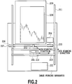
FIG. 2 is a diagram showing a configuration of an image forming apparatus in a first embodiment; -
FIG. 3 is a diagram explaining halftone representation by an area gradation method in the first embodiment; -
FIG. 4A and FIG. 4B are diagrams each explaining an operation to form a three-dimensional image in the first embodiment; -
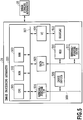
FIG. 5 is a block diagram showing a hardware configuration of an image processing apparatus in the first embodiment; -
FIG. 6 is a block diagram showing a software configuration example of a control unit in the first embodiment; -
FIG. 7A to FIG. 7C are diagrams each explaining a concept of processing that is performed by the image forming apparatus in the first embodiment; -
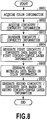
FIG. 8 is a flowchart of processing that is performed by the image processing apparatus in the first embodiment; -
FIG. 9 is a flowchart of concavity / convexity information separation processing in the first embodiment; -
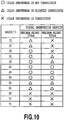
FIG. 10 is a table indicating visual observation results for patterns at a variety of inclination angles in the first embodiment; -
FIG. 11 is a flowchart of concavity / convexity information separation processing in a second embodiment; -
FIG. 12 is a block diagram showing a software configuration example of a control unit in a third embodiment; -
FIG. 13 is a flowchart of processing that is performed by an image processing apparatus in the third embodiment; -
FIG. 14 is a diagram showing the relationship ofFIGs. 14A and14B ; -
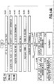
FIGs. 14A and14B are flowcharts of layer information creation processing in the third embodiment; -
FIG. 15 is an example of a lookup table in the third embodiment; -
FIG. 16 is a block diagram showing a software configuration example of a control unit in a fourth embodiment; -
FIG. 17 is a flowchart of processing that is performed by an image processing apparatus in the fourth embodiment; -
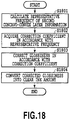
FIG. 18 is a flowchart of gloss data generation processing in the fourth embodiment; and -
FIGs. 19A and 19B are examples of tables in the fourth embodiment. - Hereinafter, embodiments of the present invention are explained with reference to the drawings. However, the following embodiments do not limit the present invention and all of the combinations of the features explained below are not necessarily indispensable for resolving the problems of the present invention. Explanation of the same configuration is given by attaching the same symbol.
- An image processing apparatus in the present embodiment generates data that can be output by an image forming apparatus that forms color material layers and concavo-convex layers on a printing medium, such as a sheet. An object to be reproduced, such as an oil painting, is substantially a two-dimensional image, but on the surface thereof, fine concavities / convexities are formed. Consequently, in the present embodiment, an oil painting is reproduced by forming color material layers and concavo-convex layers based on shape information representing the surface concavities / convexities of the oil painting and color information. In the present specification, an image including color material layers and concavo-convex layers is referred to as a three-dimensional image.
-
FIG. 5 is a configuration diagram of animage processing apparatus 24 in the present embodiment. Theimage processing apparatus 24 is connected with animage forming apparatus 25. In the present embodiment, as theimage processing apparatus 24, a personal computer on which a printer driver for theimage forming apparatus 25 is installed is supposed. Further, as theimage forming apparatus 25, an ink jet printer that forms a three-dimensional image including concavo-convex layers and color material layers by using ink is supposed. First, theimage forming apparatus 25 is explained.FIG. 2 shows an outline configuration of theimage forming apparatus 25. - A
head cartridge 201 includes a print head having a plurality of ejection ports and ink tanks that supply ink to the print head, and is further provided with a connector for receiving a signal or the like that drives each ejection port of the print head. Six types of ink tanks are provided independently of one another, one for a UV curable colorless transparent liquid resin ink for forming concavo-convex layers and the others for each color ink of cyan, magenta, yellow, black, and white for forming color material layers. Thehead cartridge 201 is mounted on acarriage 202 in an exchangeable manner after being positioned and thecarriage 202 is provided with a connector holder for transmitting a drive signal or the like to thehead cartridge 201 via the connector. Further, on thecarriage 202, an ultravioletlight irradiation device 210 is mounted. The ultravioletlight irradiation device 210 is controlled so as to cure and fix an ejected curable ink onto a printing medium. - The
carriage 202 is designed so as to be capable of reciprocating along aguide shaft 203. Specifically, thecarriage 202 is driven via drive mechanisms, such as amotor pulley 205, a drivenpulley 206, and atiming belt 207, by using amain scan motor 204 as a drive source and at the same time, the position and movement of thecarriage 202 are controlled. The movement along theguide shaft 203 of thecarriage 202 is referred to as a "main scan" and the direction of the movement is referred to as a "main scanning direction". Aprinting medium 208 is placed on asupport 209. Thehead cartridge 201 mounted on thecarriage 202 is held so that the ejection port surface protrudes downward from thecarriage 202 and becomes parallel to the printing surface of theprinting medium 208. Acontrol unit 221 includes a CPU, a storage unit, etc., and controls the operation of each component of theimage forming apparatus 25 so as to form a three-dimensional image based on data. In the present embodiment, as described above, explanation is given on the supposition that the image forming apparatus is a UV curable ink jet printer, but the image forming apparatus is not limited to this example provided that the image forming apparatus can eject the colorless transparent liquid resin ink and color ink. For example, it may also be possible to use a solid ink in place of the UV curable ink. Further, it is also possible to apply the present embodiment to an electrophotographic image forming apparatus in place of the ink jet image forming apparatus. - Hereinafter, the three-dimensional image forming operation that is performed by the ink jet printer with the configuration shown in
FIG. 2 is explained. First, in the case where theprinting medium 208 is conveyed to a predetermined printing start position, thecarriage 202 moves in the main scanning direction on theprinting medium 208 along theguide shaft 203. During the movement, inks are ejected from the ejection ports of the print head. The ultravioletlight irradiation device 210 irradiates the ejected inks with ultraviolet light in accordance with the movement of the print head to cure and fix the ejected inks onto the printing medium. Then, in the case where thecarriage 202 moves in the main scanning direction along theguide shaft 203 and reaches one end of theguide shaft 203, thecarriage 202 moves in the direction perpendicular to the main scanning direction along theguide shaft 211 by a predetermined amount. The movement of thecarriage 202 is referred to as a "sub scan" and the direction of the movement is referred to as a "sub scanning direction". After thecarriage 202 moves in the sub scanning direction by a predetermined amount, thecarriage 202 moves again in the main scanning direction along theguide shaft 203. By thecarriage 202 of the print head repeating the main scan and the sub scan in this manner, a three-dimensional image including concavo-convex layers and color material layers is formed on theprinting medium 208. -
FIG. 3 is a diagram explaining representation of an image that is controlled by an area gradation method. In the present embodiment, for simplification of explanation, it is assumed that whether the ink is ejected (on) or not ejected (off) is controlled for each pixel defined by the output resolution of the image forming apparatus and the state where all the pixels within the area are turned on is regarded as the state where the density is 100%. With a so-called binary printer that controls the on/off states of the ink for each pixel, it is possible to represent one of the on state (density is 100%) and the off state (density is 0%) with one pixel, and therefore, a halftone is represented by a set of a plurality of pixels. Explanation is given usingFIG. 3 . Instead of representing a halftone by a density of 25% as shown on the bottom left inFIG. 3 , the representation of a halftone is implemented by ejecting ink to four pixels of 16 pixels as shown on the bottom right inFIG. 3 to represent a density of 25% (= 4/16) in terms of area. It is also possible to represent another tone level similarly. The total number of pixels and the arrangement pattern of the on pixels within the area for representing a halftone are not limited to the example shown inFIG. 3 . In general, the error diffusion method is made use of for the derivation of an arrangement pattern. In the present embodiment, ejection/non-ejection of ink droplet is controlled by two values, but it may also be possible to use the multi-droplet method of controlling the amount of ink droplet by multiple values and forming one dot by causing a plurality of ink droplets to land within one pixel on a printing medium from the same ejection port. -
FIG. 4A and FIG. 4B are diagrams each explaining the operation to form a three-dimensional image by thecarriage 202 scanning on theprinting medium 208. By the main scan by thecarriage 202, an image corresponding to a width L of thecarriage 202 is formed and each time image formation of one line is completed, thecarriage 202 is moved in the sub scanning by a distance L each time. In order to make explanation easy, the maximum ink amount that the image forming apparatus in the present embodiment can eject by one main scan is represented as an ink amount of 100%. - In the case where the layer to be formed requires an ink amount exceeding 100%, it is necessary to perform the scan (main scan) a plurality of times in the same area. For example, in the case where a layer is formed by an ink amount of 500% in a certain area, the same line is scanned five times. Explanation is given using
FIG. 4A and FIG. 4B . In the case where a layer by an ink amount of 500% is formed in an area A and an area B, after scanning five times in the area A (FIG. 4A ), thecarriage 202 is conveyed by L in the sub scanning direction and the area B is scanned five times (FIG. 4B ). It may also be possible to control the ink amount by increasing the number of times of ink ejection to the same position without increasing the number of times of scan. - A hardware configuration example of the
image processing apparatus 24 in the present embodiment is shown inFIG. 5 . Acontrol unit 220 includes aCPU 501, aROM 502, aRAM 503, a general-purpose interface (hereinafter, also referred to as I/F) 504, a serial ATA (hereinafter, also referred to as SATA) I/F 505, and a video card (hereinafter, also referred to as VC) 506. These components constituting thecontrol unit 220 are connected to one another via asystem bus 507 and are capable of transmission and reception of information via thesystem bus 507. - The
CPU 501 executes an operation system (OS) and various programs stored in theROM 502, a hard disk drive (HDD) 510, various storage media mounted on a general-purpose drive 511, etc. , by using theRAM 503 as a wok memory. Due to this, theCPU 501 controls each component via thesystem bus 507. The programs executed by theCPU 501 include programs for performing processing, to be described later, in the present embodiment. The general-purpose I/F 504 is, for example, a serial bus interface, such as USB. Thecontrol unit 220 is connected with aninput device 509, such as a mouse and a keyboard, via aserial bus 508. To the SATA I/F 505, theHDD 510 and the general-purpose drive 511 that performs read and write of various storage media are connected. TheCPU 501 performs read and write of data for theHDD 510 and various storage media mounted on the general-purpose drive 511. TheVC 506 is a video interface and is connected with adisplay 512. TheCPU 501 displays a user interface (hereinafter, also referred to as UI) that is provided by program execution on thedisplay 512. Then, theCPU 501 receives user inputs including instructions of the user that are input by the user through the UI by using theinput device 509. -
FIG. 6 is a block diagram showing a software configuration example of thecontrol unit 220 in the present embodiment. As shown inFIG. 6 , thecontrol unit 220 includes a colorinformation acquisition unit 601, a concavity / convexityinformation acquisition unit 602, a concavity / convexityinformation separation unit 603, and adata generation unit 604. Thedata generation unit 604 includes a first concavity / convexitydata generation unit 605, a color materialdata generation unit 606, and a second concavity / convexitydata generation unit 607. The colorinformation acquisition unit 601 acquires color information and sends the acquired color information to the color materialdata generation unit 606. The color information is bitmap data including color values for each pixel. In the present embodiment, it is assumed that the color information has RGB values for each pixel, which are calculated from CIELAB values by the sRGB conversion formula. The concavity / convexityinformation acquisition unit 602 acquires concavity / convexity information representing concavities / convexities (shape) of a three-dimensional image desired to be output and sends the acquired concavity / convexity information to the concavity / convexityinformation separation unit 603. The concavity / convexity information is data describing a two-dimensional distribution of height. In the case where the three-dimensional image desired to be output is an oil painting, the concavity / convexity information is the height (also referred to as thickness) on a condition that the height of the canvas surface is taken to be 0. In the present embodiment, it is assumed that the concavity / convexity information is data of heights from the reference surface which each pixel holds as the pixel value, and is a gray scale image in which the height of each pixel is represented by an 8-bit pixel value. Hereinafter, this gray scale image is also referred to as a concavo-convex image. - The concavity / convexity
information separation unit 603 receives the concavity / convexity information from the concavity / convexityinformation acquisition unit 602 and separates the received concavity / convexity information into first concavo-convex layer information for forming a first concavo-convex layer beneath a color material layer and second concavo-convex layer information for forming a second concavo-convex layer on the color material layer. Then, the concavity / convexityinformation separation unit 603 sends the first concavo-convex layer information to the first concavity / convexitydata generation unit 605, and sends the second concavo-convex layer information to the second concavity / convexitydata generation unit 607. Like the concavity / convexity information, the first concavo-convex layer information and the second concavo-convex layer information are data of heights from the reference surface which each pixel holds as the pixel value, and is a gray scale image in which the height of each pixel is represented by an 8-bit pixel value. The separation method of concavity / convexity information and details of the first concavo-convex layer information and the second concavo-convex layer information will be described later. - The first concavity / convexity
data generation unit 605 receives the first concavo-convex layer information from the concavity / convexityinformation separation unit 603 and converts the received first concavo-convex layer information into first concavity / convexity data that theimage forming apparatus 25 can output. Here, the first concavity / convexity data is divided into pieces of data corresponding to a plurality of times of scan in accordance with the height (thickness) that theimage forming apparatus 25 can form by a single scan. The color materialdata generation unit 606 receives color information from the colorinformation acquisition unit 601 and converts the received color information into color material data that theimage forming apparatus 25 can output. Here, the image data including RGB values is converted into data of color materials (e.g., cyan, magenta, black, yellow) that theimage forming apparatus 25 outputs. Further, after the color conversion into each color, various kinds of processing, such as halftone processing into the number of tone levels that theimage forming apparatus 25 can output, are performed. The second concavity / convexitydata generation unit 607 receives the second concavo-convex layer information from the concavity / convexityinformation separation unit 603 and converts the received second concavo-convex layer information into second concavity / convexity data that theimage forming apparatus 25 can output. Theimage forming apparatus 25 acquires the first concavity / convexity data, the color material data, and the second concavity / convexity data that are generated in the image processing apparatus. Theimage forming apparatus 25 forms a three-dimensional image on a printing medium based on the acquired data. - Hereinafter, an outline of the processing in the present embodiment, which is performed by the above-described ink jet printer, is explained. The fact has been described previously that the
portion 103 where the color material layer is thin will appear because the entire concavo-convex surface is not coated in the case where colors and concavities / convexities are reproduced by the layer stacking method and on a condition that the inclination angle P of the slope is large as shown inFIG. 1C . On the other hand, in the case where the inclination angle α of the slope is small as shown inFIG. 1B , the entire concavo-convex surface is coated and the thickness of the color material layer will become substantially the same. The image processing apparatus according to the present embodiment generates data for forming a three-dimensional image by taking into consideration this characteristic. -
FIG. 7A to FIG. 7C are conceptual diagrams of the processing in the present embodiment.FIG. 7A is a section diagram showing an example of a concavo-convex shape that is reproduced by concavity / convexity information that the concavity / convexityinformation acquisition unit 602 acquires. The concavity / convexityinformation separation unit 603 separates the concavity / convexity information, for example, into the first concavo-convex layer information for reproducing the concavo-convex shape shown by slashes inFIG. 7B and the second concavo-convex layer information for reproducing the concavo-convex shape shown by slashes inFIG. 7C . Here, the concavo-convex shape that is reproduced by the first concavo-convex layer information is a shape onto which ink can settle because the inclination angle of the slope is small as shown inFIG. 7B . On the other hand, as shown inFIG. 7C , the concavo-convex shape that is reproduced by the second concavo-convex layer information is a shape that is a difference between the concavo-convex shape shown inFIG. 7A and the concavo-convex shape shown inFIG. 7B . In the present embodiment, explanation is given on the assumption that the first concavo-convex layer is formed by using a clear ink, which is the UV curable colorless transparent liquid resin and that the first concavity / convexity data is bitmap data in which the pixel value of each pixel is the clear ink amount in accordance with the height of concavities / convexities. However, the ink used to form the fist concavo-convex layer is not limited to this ink. For example, the clear ink amount may be a color ink amount, such as a white ink amount. The color material layer data is the ink amounts of colors, such as a cyan, magenta, yellow, black, and white. It is desirable that the second concavo-convex layer be formed by the clear ink, which is the UV curable colorless transparent liquid resin, in order not to block observation of the color material layer. - As explained above, in the present embodiment, the first concavo-convex layer having an inclination angle that enables the color material to settle is formed beneath the color material layer. Then, by forming the color material layer and the second concavo-convex layer on the first concavo-convex layer, a three-dimensional image is formed, and thereby, the colors and concavities / convexities are reproduced on a printing medium. From the standpoint of reproducibility of concavities / convexities, it is desirable that the liquid drop size be less than or equal to 50 pl in the case where the height is controlled in the vicinity of 80 µm, and the liquid drop size be less than or equal to 90 pl in the case where the height is controlled in the vicinity of 100 µm. Consequently, in the case where the concavo-convex layer consisting of the first concavo-convex layer and the second concavo-convex layer becomes about several hundred µm to several mm thick, the object to be reproduced will seem unnatural, and therefore, it is desirable that both the fist concavo-convex layer and the second concavo-convex layer be formed with a liquid drop size of 50 pl or less.
- Hereinafter, the processing in the present embodiment that is performed by the above-described
image processing apparatus 24 is explained usingFIG. 8 . Each unit shown inFIG. 6 is implemented by theCPU 501 reading and executing the program corresponding to the flowchart shown inFIG. 8 . At step S801, the colorinformation acquisition unit 601 acquires color information on the reproduction target. The color information acquired at this step is sent to the color materialdata generation unit 606. At step S802, the concavity / convexityinformation acquisition unit 602 acquires concavity / convexity information (concavo-convex image) on the reproduction target. The concavity / convexity information acquired at this step is sent to the concavity / convexityinformation separation unit 603. As described previously, the concavity / convexity information is data of heights from the reference surface which each pixel holds as the pixel value, and is a gray scale image in which the height of each pixel is represented by an 8-bit pixel value. - At step S803, the concavity / convexity
information separation unit 603 calculates the inclination angle of the concavo-convex image for each pixel and separates the concavity / convexity information into the first concavo-convex layer information and the second concavo-convex layer information based on the calculated inclination angle. After the separation, the first concavo-convex layer information is sent to the first concavity / convexitydata generation unit 605 and the second concavo-convex layer information is sent to the second concavity / convexitydata generation unit 607. Details of step S803 will be described later. - At step S804, the first concavity / convexity
data generation unit 605 generates first concavity / convexity data for constructing part of the reproduction-target concavities / convexities based on the first concavo-convex layer information. In the present embodiment, the pixel value of the first concavo-convex layer information represented by an 8-bit gray scale is normalized in the range of 0 to 1 (0% to 100%) and the normalized pixel value is associated with the ink amount. For example, a pixel value of 255 in the first concavo-convex layer information corresponds to an ink amount of 100% and a pixel value of 128 corresponds to an ink amount of 50%. Here, in accordance with the ejected ink amount, a layer that is formed has a certain thickness, i.e., a certain height. Consequently, for example, in the case where a layer formed by an ink amount of 100% has a thickness of 20 µm, it is necessary to stack the layer formed by an ink amount of 100% five times in order to reproduce a height of 100 µm. In other words, in this case, the first concavo-convex layer having a height of 100 µm is formed by performing the main scan five times with an ink amount of 100%. - At step 5805, the color material
data generation unit 606 generates color material data having, as a pixel value, an ink amount for forming a color material layer that is formed by color ink based on the color information. The color material data is generated so as to include an ink amount of a spot color ink for hiding the background in order to suppress the influence of the change in color due to a printing medium. In the present embodiment, it is assumed that the color material data is data of five channels in total storing the ink amount of a white ink as a spot color ink for hiding the background, in addition to the ink amounts of cyan, magenta, yellow, and black described previously. At step S806, the second concavity / convexitydata generation unit 607 generates second concavity / convexity data for constructing the second concavo-convex layer the inclination angle of which is larger than that of the first concavo-convex layer based on the second concavo-convex layer information. In the case where the second concavity/convexity data is generated, as in the case where the first concavo-convex layer is formed, the ink amount is derived from the pixel value in the second concavo-convex layer information (gray scale image) based on the correspondence relationship between the height and the ink amount. After the above processing is completed, theimage processing apparatus 24 outputs the first concavity / convexity data, the color material data, and the second concavity / convexity data to theimage forming apparatus 25. - Hereinafter, separation processing of concavity / convexity information (step S803 in
FIG. 8 ) is explained in detail usingFIG. 9 . At step S901, the concavity / convexityinformation separation unit 603 sets a variable (x, y) representing the pixel position to (0, 0), which is the initial value. At step S902, the concavity / convexityinformation separation unit 603 acquires a pixel value h (x, y) at coordinates (x, y) of the concavity / convexity information. - At step S903, the concavity / convexity
information separation unit 603 acquires a pixel value h1 (x-1, y) at coordinates (x-1, y) of the first concavo-convex layer information. However, in the case where x = 0, the corresponding pixel value does not exist, and therefore, the pixel value h1 (x-1, y) is found by expression (1) below.
- At step S904, the concavity / convexity
information separation unit 603 calculates an inclination angle θ based on h (x, y) acquired at step S902 and h1 (x-1, y) acquired at step S903 by using expression (2) below. In expression (2), R is the resolution (dpi) of the concavity / convexity information (gray scale image). Further, hmax is the height (mm) corresponding to the maximum pixel value that the pixel value can take in the concavity / convexity information (the maximum value is 255 because the concavity / convexity information is a gray scale image represented by an 8-bit pixel value in the present embodiment).
- At step S905, the concavity / convexity
information separation unit 603 determines whether or not the absolute value |θ| of the inclination calculated at step S904 is less than or equal to a predefined threshold angle θ0 by expression (3) below. In the case where the concavity / convexityinformation separation unit 603 determines that the absolute value |θ| of the inclination satisfies expression (3), the processing proceeds to step S906 and in the case where the concavity / convexityinformation separation unit 603 determines that the absolute value |θ| of the inclination does not satisfy expression (3), the processing proceeds to step S907. Here, θ0 is an angle at which the slope of the first concavo-convex layer can be coated with color ink and the color is viewed appropriately in the reproduced object. Particularly, it is desirable that θ0 be the maximum angle of the angles such as the above.
- In the present embodiment, the threshold angle θ0 is determined in advance by outputting triangular waveform patterns having a variety of inclination angles and by observing three-dimensional images formed by ejecting color ink thereon. The reason is that it is possible to estimate the coated state on the slope of the first concavo-convex layer based on the results of the observation such as this. However, the method of determining θ0 is not limited to the method described previously. For example, in the case of a shape the inclination angle of which is controlled, the shape of the first concavo-convex layer does not need to be a triangular waveform. Further, it may also be possible for a use to directly specify θ0.
- In the present embodiment, the threshold angle θ0 is determined by observing three-dimensional images formed by ejecting color ink on 13 kinds of triangular waveform patterns in which the inclination angle is changed by 5° each time the inclination angle is changed in the range from 15° to 75°. Specifically, the 13 kinds of patterns described previously are formed by a colorless transparent liquid resin ink and each pattern of the 13 kinds of patterns that are formed is coated with the color material layer formed by color ink. Then, on the color material layer, a layer is formed by the colorless transparent liquid resin ink so that the maximum height of the three-dimensional image having a three-layer structure becomes 100 µm or 500 µm. The three-dimensional images thus formed are observed visually.
FIG. 10 is a diagram showing the results of the observation. As shown inFIG. 10 , both in the case where the maximum height is 100 µm and in the case where the maximum height is 500 µm, on a condition that the inclination angle is more than or equal to 65°, the results are that color unevenness is conspicuous. The reason is that the thickness of the color material layer on the layer of the triangular waveform pattern is no longer uniform in the case where the inclination angle is more than or equal to 65°, and therefore, the density unevenness of color ink occurs. On the other hand, in the case where the inclination angle is small, the triangular waveform pattern is coated with the color material layer (color ink), but resulting from that the thickness of the uppermost layer that is formed by the colorless transparent liquid resin ink becoming great, the phenomenon in which the color seems cloudy was observed. This phenomenon is particularly noticeable in the case where the maximum height is 500 µm, and the results are that color unevenness is conspicuous in the case where the inclination angle is less than or equal to 25°. From the above results, preferably, θ0 is a value within the range not less than 30° and not more than 60°, and more preferably, θ0 is a value within the range not less than 40°and not more than 50°. In the present embodiment, θ0 is taken to be 45° (θ0 = 45°). - At step S906, the concavity / convexity
information separation unit 603 takes the pixel value h1 (x, y) at the coordinates (x, y) of the first concavo-convex layer information to be the pixel value h (x, y) of the concavity / convexity information as shown in expression (4). At step S905 in the previous stage, it is determined that the absolute value of θ is less than or equal to θ0, i.e., it is determined that the color can be reproduced appropriately in the case where coating by color ink is performed for the concavities / convexities that are reproduced based on the concavity / convexity information. Consequently, at this step, the pixel value h (x, y) of the concavo-convex layer information is used as the pixel value h1 (x, y) of the first concavo-convex layer information as it is.
- At step S907, the concavity / convexity
information separation unit 603 calculates the pixel value h1 (x, y) at the coordinates (x, y) of the first concavo-convex layer information by expression (5) or expression (6). At step S905 in the previous stage, it is determined that the absolute value of θ is greater than θ0, i.e., it is determined that it is difficult to appropriately reproduce the color in the case where coating by color ink is performed for the concavities / convexities that are reproduced based on the concavity / convexity information. Consequently, at this step, the pixel value h1 of the first concavo-convex layer information is generated so that the slope has the angle θ0 at which coating is possible.

- At step S908, the concavity / convexity
information separation unit 603 finds a pixel value h2 (x, y) at the coordinates (x, y) of second concavo-convex layer information by taking a difference between the pixel value h (x, y) of the concavity / convexity information and the pixel value h1 (x, y) of the first concavo-convexity layer information as expressed by expression (7).
- At step S909, the concavity / convexity
information separation unit 603 determines whether or not the processing to find the pixel values h1 and h2 has been completed for all the pixels. In the case where the concavity / convexityinformation separation unit 603 determines that the processing to find the pixel values h1 and h2 has been completed for all the pixels, the processing at S803 is completed. On the other hand, in the case where the concavity / convexityinformation separation unit 603 determines that the processing to find the pixel values h1 and h2 has not been completed for all the pixels, the processing proceeds to step S910. At step S910, the concavity / convexityinformation separation unit 603 updates the variable (x, y) representing the pixel position in order to find the pixel values h1 and h2 for the pixel on which the processing has not been performed yet. Next, the processing returns to step S902. - As above, the separation processing of the concavity / convexity information at step S803 is explained in detail. By performing the above-described processing, it is possible to separate the concavity / convexity information into the first concavo-convex layer information for forming the first concavo-convex layer, on which the color material layer having substantially the uniform thickness can be formed, and the second concavo-convex layer information for forming the second concavo-convex layer, on which it is difficult to form the color material layer having substantially the uniform thickness.
- According to the present embodiment, the concavity / convexity information is separated into the first concavo-convex layer information for forming the first concavo-convex layer beneath the color material layer and the second concavo-convex layer information for forming the second concavo-convex layer on the color material layer. Then, the first concavity / convexity data for forming the first concavo-convex layer beneath the color material layer, the color material data based on the color information, and the second concavity/convexity data for forming the second concavo-convex layer on the color material layer are generated. Due to this, even in the case where there is a steep slope on the surface of the reproduced object, it is made possible to prevent color reproduction accuracy from being reduced. Further, at this time, the shape of the second concavo-convex layer is a shape that is a difference between the shape of the reproduction-target concavities / convexities and the shape of the first concavo-convex layer, and the thickness of the second concavo-convex layer that is stacked on the color material layer is less than that of the first concavo-convex layer. Consequently, the amount of deviation in the position of the light that is reflected from the color material layer becomes smaller, which results from the refraction of the light that occurs in the second concavo-convex layer on the surface, and therefore, it is made possible to favorably reproduce the concavities / convexities and the colors.
- At the pixel position at which the absolute value of θ is determined to be less than or equal to θ0 at step S905, the concavities / convexities that are reproduced based on the concavity / convexity information can be reproduced by the first concavo-convex layer alone that is formed based on the first concavo-convex layer information. Consequently, the three-dimensional image formed by the
image forming apparatus 25 is formed by the two layers, i.e., the first concavo-convex layer and the color material layer, in the area where the absolute value of the inclination angle is less than or equal to the threshold angle (|θ|≤ θ0). On the other hand, in the area where the absolute value of the inclination angle is greater than the threshold angle (|θ| > θ0), the three-dimensional image is formed by the three layers, i.e., the first concavo-convex layer, the color material layer, and the second concavo-convex layer. - Further, in the present embodiment, the color information and the second concavo-convex layer information are handled independently of each other. However, there is a case where the appearance of a color varies depending on the thickness of the second concavo-convex layer that is controlled based on the second concavo-convex layer information. Consequently, it may also be possible to adjust the color information in accordance with the thickness of the second concavo-convex layer. In this case, it is sufficient to perform color conversion based on the relationship between the amount of colorless transparent liquid resin ink to be ejected, which is necessary to form the second concavo-convex layer, and the color ink.
- Further, in the present embodiment, the case is explained where the concavity / convexity information is separated into the two pieces of concavo-convex layer information: the first concavo-convex layer information and the second concavo-convex layer information. However, it may also be possible to separate the concavity / convexity information into three or more pieces of concavo-convex layer information. It is also possible to apply the present embodiment to the case where the concavity / convexity information is separated into three or more pieces of concavo-convex layer information, provided that the lowermost layer and the uppermost layer are concavo-convex layers and the color material layer is formed therebetween.
- In the first embodiment, the inclination angle θ of the slope is calculated for each pixel and the concavity / convexity information is separated into the first concavo-convex layer information and the second concavo-convex layer information. However, the method of separating concavity / convexity information is not limited to the method that uses the inclination angle. For example, in the case where concavity / convexity information is frequency-resolved, there is a tendency for the low-frequency component to include many gradual shapes and for the high-frequency component to include many steep shapes. Consequently, it is also possible to obtain the same effects as those of the first embodiment by separating concavity / convexity information in accordance with the frequency component. Hereinafter, the case is explained where concavity / convexity information is separated into the low-frequency component and the high-frequency component. However, in the following explanation, explanation of the contents in common to those of the first embodiment is simplified or omitted.
- Hereinafter, separation processing of concavity / convexity information (step S803 in
FIG. 8 ) in the second embodiment is explained in detail usingFIG. 11 . At step S1101, the concavity / convexityinformation separation unit 603 calculates a Gaussian filter F (a, b) by expression (8) below as a low-pass filter.
- A variance S of the Gaussian filter in expression (8) is calculated by expression (9) below by using the resolution R of concavity / convexity information (gray scale image).

- In the present embodiment, the concavity / convexity space period more than or equal to 0.1 mm is regarded as a low frequency and a filter for extracting the frequency component less than or equal to the concavity / convexity space frequency corresponding thereto is created, but the frequency component is not limited to this example. For example, it may also be possible for a user to specify the frequency component.
- At step S1102, the concavity / convexity
information separation unit 603 performs a convolution operation of the concavity / convexity information and the low-pass filter created at step S1101 in accordance with expression (10) below.
- In expression (10), M is the number of pixels in the horizontal direction of the concavity / convexity information (gray scale image) and N is the number of pixels in the vertical direction of the concavity / convexity information (gray scale image). At step S1103, the concavity / convexity
information separation unit 603 sets the first concavo-convex layer information to convolution operation results h' that are found at step S1102. - At step S1104, the concavity / convexity
information separation unit 603 calculates a difference between the pixel value h (x, y) of the concavity / convexity information and the pixel value h1 (x, y) of the first concavo-convex layer information that is found at step S1103 and finds the pixel value h2 (x, y) of the second concavo-convex layer information for each pixel. Due to this, the concavity / convexityinformation separation unit 603 creates the second concavo-convex layer information. By the present embodiment, it is made possible to prevent color reproduction accuracy from being reduced even in the case where there is a steep slope on the surface of the reproduced object. Further, in the present embodiment, the concavity / convexity information is separated into the first concavo-convex layer information and the second concavo-convex layer information without using the inclination angle of the slope. Consequently, it is not necessary to perform in advance the process (observation or the like) to determine the threshold angle θ0 as described in the first embodiment. - In the first and second embodiments, the concavity / convexity information is separated into the first concavo-convex layer information and the second concavo-convex layer information and the data for forming the first concavo-convex layer and the second concavo-convex layer is generated by using the colorless transparent liquid resin ink. Further, at this time, concavities / convexities and colors are reproduced by forming the color material layer of color ink between the first concavo-convex layer and the second concavo-convex layer.
- On the other hand, it is also possible to reproduce colors while reproducing concavities / convexities having steep inclination angles by forming the concavo-convex layer by using color ink in place of the colorless transparent liquid resin ink. However, in the case where concavities / convexities are reproduced by color ink, there is a possibility that a desired color cannot be reproduced because of the change in density caused by stacking a plurality of color material layers. For example, in reproducing an object that is a single color and the thickness of which varies, in the case where an attempt is made to reproduce concavities / convexities by color ink alone, there is a possibility that the appearance of a color will be different between the portion where the thickness of the color material layer is small and the portion where the thickness of the color material layer is great.
- In view of the above-described contents, in the present embodiment, both the methods are used: the method of reproducing concavities / convexities and colors by the colorless transparent liquid resin ink and color ink as in the first and second embodiment and the method of reproducing concavities / convexities and colors by color ink alone. Hereinafter, the present embodiment is explained in detail. However, in the following explanation, explanation of the contents in common to those of the first and second embodiments is simplified or omitted.
-
FIG. 12 is a block diagram showing a software configuration example of thecontrol unit 220 in the present embodiment. As shown inFIG. 12 , thecontrol unit 220 includes a colorinformation acquisition unit 1201, a concavity / convexityinformation acquisition unit 1202, a lookup table (hereinafter, also referred to as LUT)holding unit 1203, a layerinformation creation unit 1204, and adata generation unit 1205. Thedata generation unit 1205 includes a first concavity / convexitydata generation unit 1206, a color materialdata generation unit 1207, and a second concavity / convexitydata generation unit 1208. - The color
information acquisition unit 1201 and the concavity / convexityinformation acquisition unit 1202 are the same as the colorinformation acquisition unit 601 and the concavity / convexityinformation acquisition unit 602 of the first embodiment, and therefore, explanation thereof is omitted. TheLUT holding unit 1203 holds an LUT. Details of the LUT held by theLUT holding unit 1203 will be described later. The layerinformation creation unit 1204 receives concavity / convexity information from the concavity / convexityinformation acquisition unit 1202 as well as receiving color information from the colorinformation acquisition unit 1201. Then, the layerinformation creation unit 1204 creates color material layer information, first concavo-convex layer information, and second concavo-convex layer information based on the received color information and concavity / convexity information by using the LUT held by theLUT holding unit 1203. Then, the layerinformation creation unit 1204 sends the first concavo-convex layer information to the first concavity / convexitydata generation unit 1206, the color material layer information to the color materialdata generation unit 1207, and the second concavo-convex layer information to the second concavity / convexitydata generation unit 1208. The color material layer information is data that is used for forming a color material layer and is data that includes the color value and the number of times of stacking, which indicates the number of stacked layers of color ink, for each pixel. The first concavo-convex layer information and the second concavo-convex layer information are the same as those of the first embodiment. - The first concavity / convexity
data generation unit 1206 receives the first concavo-convex layer information from the layerinformation creation unit 1204 and generates first concavity / convexity data based on the received first concavo-convex layer information. The color materialdata generation unit 1207 receives the color material layer information from the layerinformation creation unit 1204 and generates color material data based on the received color material layer information. The second concavity / convexitydata generation unit 1208 receives the second concavo-convex layer information from the layerinformation creation unit 1204 and generates second concavity / convexity data based on the received second concavo-convex layer information. - Hereinafter, processing that is performed by the
image processing apparatus 24 in the present embodiment is explained usingFIG. 13 . Step S1301 and step S1302 are the same as step S801 and step S802 in the first embodiment, and therefore, explanation thereof is omitted. - At step S1303, the layer
information creation unit 1204 creates layer information based on the color information acquired at step S1301 and the concavity / convexity information acquired at step S1302 by using the LUT held by theLUT holding unit 1203. The layer information referred to here includes the color material layer information used for forming a color material layer that is formed by color ink, and the first concavo-convex layer information and the second concavo-convex layer information used for forming the first concavo-convex layer and the second concavo-convex layer that are formed by the colorless transparent liquid resin ink. Details of step S1303 will be described later. - At step S1304, the first concavity / convexity
data generation unit 1206 generates the first concavity / convexity data for constructing part of the reproduction-target concavities / convexities based on the first concavo-convex layer information created at step S1303. At step S1305, the color materialdata generation unit 1207 generates the color material data based on the color material layer information created at step S1303. As described previously, in the present embodiment, the reproduction-target color is reproduced by the color material layer, but as the case may be, the reproduction-target concavities / convexities are also reproduced by the color material layer. At step S1306, the second concavity / convexitydata generation unit 1208 generates the second concavity / convexity data for constructing part of the reproduction-target concavities / convexities based on the second concavo-convex layer information created at step S1303. - Hereinafter, creation processing of the layer information (step S1303 in
FIG. 13 ) is explained usingFIGs. 14A and14B . At step S1401, the layerinformation creation unit 1204 sets the variable (x, y) representing the pixel position to (0, 0), which is the initial value. At step S1402, the layerinformation creation unit 1204 acquires the pixel value h (x, y) at the coordinates (x, y) of the concavity / convexity information. At step S1403, the layerinformation creation unit 1204 acquires a pixel value RGB (x, y) at the coordinates (x, y) of the color information. - At step S1404, the layer
information creation unit 1204 acquires the LUT from theLUT holding unit 1203. Here, an example of the LUT that is held by theLUT holding unit 1203 is shown inFIG. 15 . As shown inFIG. 15 , in the LUT, combinations of colors of RGB each having nine tone levels at equal intervals are held. Here, hRGB represents the height (mm) of one color material layer formed by the color ink of each of RGB values. In the LUT, CIELab values measured by forming color material layers with one to a plurality of layers by the color ink of each of RGB values are also held. In the present embodiment, the number of tone levels of the RGB values is taken to be nine, respectively, but the number of tone levels is not limited to this example. Further, as the height of the color material layer that is formed by the color ink of each of RGB values, the height hRGB of one color material layer is used, but it may also be possible to use the height of a plurality of (e. g. , two) color material layers as the height of the color material layer that is formed by the color ink of each of RGB values. - At step S1405, the layer
information creation unit 1204 calculates a number k of times of stacking of color ink by expression (11), which is necessary to reproduce the height indicated by h (x, y) acquired at step S1402 by the color ink corresponding to RGB (x, y) acquired at step S1403.
- At step S1406, the layer
information creation unit 1204 acquires the Lab values in the case where one layer is stacked and the Lab values in the case where k layers are stacked by referring to the LUT acquired at step S1404 for the ink corresponding to RGB (x, y) acquired at step S1403. Then, the layerinformation creation unit 1204 calculates a color difference ΔE based on the acquired Lab values by using expression (12).
- At step S1407, the layer
information creation unit 1204 determines whether or not the color difference ΔE calculated at step S1406 is less than or equal to a predetermined threshold value ε by expression (13). In the present embodiment, ε is assumed to be 3.2. In the case where the layerinformation creation unit 1204 determines that expression (13) is satisfied, the change in color does not occur even by stacking a plurality of layers of the color ink, and therefore, it is determined that the reproduction-target concavities / convexities can be reproduced by the color ink alone. At this time, the processing proceeds to step S1408. On the other hand, in the case where the layerinformation creation unit 1204 determines that expression (13) is not satisfied, it is determined that the color changes on a condition that a plurality of layers of the color ink is stacked. At this time, the processing proceeds to step S1411. The processing at step S1411 and subsequent steps is the processing to generate the first concavo-convex layer information for forming the first concavo-convex layer beneath the color material layer and the second concavo-convex layer information for forming the second concavo-convex layer on the color material layer based on the concavity / convexity information in order to reproduce the reproduction-target concavities / convexities as in the first embodiment. In the present embodiment, ε is assumed to be 3.2, but it may also be possible to use another value.
- At step S1408, the layer
information creation unit 1204 sets the pixel value h1 (x, y) at the coordinates (x, y) of the first concavo-convex layer information to 0. At step S1409, the layerinformation creation unit 1204 sets the pixel value at the coordinates (x, y) of the color material layer information to (R (x, y), G (x, y), B (x, y), k). At step S1410, the layerinformation creation unit 1204 sets the pixel value h2 (x, y) at the coordinates (x, y) of the second concavo-convex layer information to 0. The processing at step S1411 to step S1419 is substantially the same as that in the first embodiment. - At step S1411, the layer
information creation unit 1204 acquires the pixel value h1 (x-1, y) at the coordinates (x-1, y) of the first concavo-convex layer information. However, in the case where x = 0, the pixel value h1 (x-1, y) is found by expression (1). At step S1412, the layerinformation creation unit 1204 calculates the inclination angle θ by expression (2) based on h (x, y) acquired at step S1402 and h1 (x-1, y) acquired at step S1411. At step 1413, the layerinformation creation unit 1204 determines whether or not the absolute value |θ| of the inclination calculated at step S1412 is less than or equal to the predetermined threshold angle θ0 by expression (3). At step S1414, the layerinformation creation unit 1204 sets the pixel value h1 (x, y) at the coordinates (x, y) of the first concavo-convex layer information to the pixel value h (x, y) of the concavity / convexity information acquired at step S1402. - At step S1415, the layer
information creation unit 1204 calculates the pixel value h1 (x, y) at the coordinates (x, y) of the first concavo-convex layer information by expression (5) or expression (6). At step S1416, the layerinformation creation unit 1204 sets the pixel value at the coordinates (x, y) of the color material layer information to (R (x, y), G (x, y), B (x, y), 1). At step S1417, the layerinformation creation unit 1204 finds the pixel value h2 (x, y) at the coordinates (x, y) of the second concavo-convex layer information by taking a difference between the pixel value h (x, y) of the concavity / convexity information and the pixel value h1 (x, y) of the first concavo-convex layer information. At step S1418, the layerinformation creation unit 1204 determines whether or not the processing to find the pixel values h1 and h2 has been completed for all the pixels. At step S1419, the layerinformation creation unit 1204 updates the variable (x, y) representing the pixel position in order to find the pixel values h1 and h2 for the pixel on which the processing has not been performed yet. - By the present embodiment, even in the case where there is a steep slope on the surface of the reproduction target, it is made possible to prevent color reproduction accuracy from being reduced. Further, in the present embodiment, part of the concavities / convexities are reproduced by the color ink, and therefore, it is possible to reduce the amount of consumed colorless transparent liquid resin ink accordingly.
- In the first and second embodiments, concavities / convexities and colors are reproduced by separating the concavity / convexity information into the first concavo-convex layer information and the second concavo-convex layer information and by forming the color material layer of the color ink between the first concavo-convex layer and the second concavo-convex layer. However, the uppermost layer of a three-dimensional image that is formed does not necessarily need to be the second concavo-convex layer. For example, it may also be possible to form a gloss control layer for controlling gloss on the second concavo-convex layer. In the present embodiment, the case is explained where a gloss control layer is further formed on the second concavo-convex layer. However, in the following explanation, explanation of the contents in common to those of the first to third embodiments is simplified or omitted.
-
FIG. 16 is a block diagram showing a software configuration example of thecontrol unit 220 in the present embodiment. - As shown in
FIG. 16 , the control unit 200 includes a colorinformation acquisition unit 1601, a concavity / convexityinformation acquisition unit 1602, a glossinformation acquisition unit 1603, a concavity / convexityinformation separation unit 1604, atable holding unit 1605, and adata generation unit 1606. Thedata generation unit 1606 includes a first concavity / convexitydata generation unit 1607, a color materialdata generation unit 1608, a second concavity / convexitydata generation unit 1609, and a glossdata generation unit 1610. - The color
information acquisition unit 1601 and the concavity / convexityinformation acquisition unit 1602 are the same as the colorinformation acquisition unit 601 and the concavity / convexityinformation acquisition unit 602 of the first embodiment, and therefore, explanation thereof is omitted. The glossinformation acquisition unit 1603 acquires gloss information representing a distribution of gloss of a three-dimensional image desired to be output and sends the acquired gloss information to the glossdata generation unit 1610. The gloss information is assumed to be a gray scale image in which the specular glossiness obtained by PM1-M is represented by an 8-bit pixel value. The concavity / convexityinformation separation unit 1604 receives concavity / convexity information from the concavity / convexity information acquisition unit and separates the received concavity / convexity information into first concavo-convex layer information and second concavo-convex layer information. Then, the concavity / convexityinformation separation unit 1604 sends the first concavo-convex layer information to the first concavity / convexitydata generation unit 1607 and the second concavo-convex layer information to the second concavity / convexitydata generation unit 1609 and to the glossdata generation unit 1610. Thetable holding unit 1605 holds an LUT for converting gloss information into gloss data. Details of the table held by thetable holding unit 1605 will be described later. The first concavity / convexity data generation unit, the color material data generation unit, and the second concavity / convexity data generation unit are the same as those of the first and second embodiments. The glossdata generation unit 1610 receives the second concavo-convex layer information from the concavity / convexityinformation separation unit 1604 as well as receiving the gloss information from the glossinformation acquisition unit 1603. Then, the glossdata generation unit 1610 generates the gloss data for forming a glossy layer on a printing medium based on the received gloss information and second concavo-convex layer information by using the LUT held by thetable holding unit 1605. - Hereinafter, processing that is performed by the image processing apparatus in the present embodiment is explained using
FIG. 17 . Step S1701 and step S1702 are the same as step S801 and step S802 in the first embodiment, and therefore, explanation thereof is omitted. At step S1703, the glossinformation acquisition unit 1603 acquires the gloss information representing the distribution of gloss of the reproduction-target three-dimensional image. Step S1704 to step S1707 are the same as step S803 to step S806 in the first embodiment, and therefore, explanation thereof is omitted. At step S1708, the glossdata generation unit 1610 generates the gloss data from the gloss information by using the second concavo-convex layer information and the LUT held by thetable holding unit 1605. Specifically, the glossdata generation unit 1610 generates the gloss data for forming a glossy layer on the second concavo-convex layer by converting the glossiness into a clear ink amount. Details of step S1708 will be described later. - Hereinafter, details of gloss data generation processing (step S1708 in
FIG. 17 ) are explained usingFIG. 18 . At step S1801, the glossdata generation unit 1610 calculates a representative frequency that characterizes the second concavo-convex layer information (indicated by h2). In order to calculate the representative frequency, first, the second concavo-convex layer information h2 is resolved into frequency components by using the publicly known Fourier transformation as shown in expression (14). However, the method that is used to resolve into frequency components is not limited to the Fourier transformation. For example, it may also be possible to use the wavelet conversion.
- Next, the representative frequency (indicated by fmax) that characterizes the second concavo-convex layer information is calculated by expression (15) by using a frequency-resolved image A (u, v). In expression (15), argxmax (g (x)) is a function to find a variable x that maximizes a function g (x). In the present embodiment, as shown in expression (15), the maximum amplitude value in the frequency space is taken to be the representative frequency that characterizes the second concavo-convex layer information, but the frequency that characterizes the concavity / convexity information is not limited to this. For example, the representative frequency may be a statistical value, such as the average frequency and the median of the frequency.

- At step S1802, the gloss
data generation unit 1610 acquires a correction coefficient of the gloss corresponding to the representative frequency of the second concavo-convex layer information calculated at step S1801 from the correction table held by thetable holding unit 1605. Here, an example of the correction table held by thetable holding unit 1605 is shown inFIG. 19A . As shown inFIG. 19A , in the correction table, a frequency f of concavities / convexities and a correction coefficient α for correcting gloss are associated with each other. In general, as the frequency of concavities / convexities increases, the specular glossiness decreases. Consequently, the correction coefficient becomes smaller as the frequency of concavities / convexities increases as shown inFIG. 19A . In the case where a value corresponding to the frequency fmax does not exist in the table, the correction coefficient is calculated by the publicly known linear interpolation. - At step S1803, the gloss
data generation unit 1610 corrects the glossiness by expression (16) by using the correction coefficient acquired at step S1802 and calculates corrected glossiness (indicated by Gout). In expression (16), Gin is the glossiness acquired at step S1703 and α is the correction coefficient acquired at step S1802.
- At step S1804, the gloss
data generation unit 1610 converts the glossiness Gout acquired at step S1803 into the amount of ink (clear ink) for gloss control by using the table held by thetable holding unit 1605 and terminates the processing. In the present embodiment, the specular glossiness is controlled by applying a clear ink amount to the uppermost surface of the image under predetermined conditions, such as the dot pattern and the number of paths based on the ink amount and by changing the surface roughness. InFIG. 19B , an example of the conversion table for converting the glossiness into the clear ink amount is shown. As shown inFIG. 19B , the glossiness and the clear ink amount (%) are associated with each other. In the case where a value corresponding to the glossiness Gout does not exist in the table, the clear ink amount is acquired by the publicly known linear interpolation. - By the present embodiment, it is made possible to control gloss by providing a glossy layer on the second concavo-convex layer. At this time, the glossiness is converted into the amount of ink for gloss control in view of the gloss that changes depending on the shape of the second concavo-convex layer, and therefore, it is possible to control gloss more appropriately.
- Embodiment(s) of the present invention can also be realized by a computer of a system or apparatus that reads out and executes computer executable instructions (e.g., one or more programs) recorded on a storage medium (which may also be referred to more fully as a 'non-transitory computer-readable storage medium') to perform the functions of one or more of the above-described embodiment (s) and/or that includes one or more circuits (e.g., application specific integrated circuit (ASIC)) for performing the functions of one or more of the above-described embodiment (s), and by a method performed by the computer of the system or apparatus by, for example, reading out and executing the computer executable instructions from the storage medium to perform the functions of one or more of the above-described embodiment(s) and/or controlling the one or more circuits to perform the functions of one or more of the above-described embodiment(s). The computer may comprise one or more processors (e.g. , central processing unit (CPU), micro processing unit (MPU)) and may include a network of separate computers or separate processors to read out and execute the computer executable instructions. The computer executable instructions may be provided to the computer, for example, from a network or the storage medium. The storage medium may include, for example, one or more of a hard disk, a random-access memory (RAM), a read only memory (ROM), a storage of distributed computing systems, an optical disk (such as a compact disc (CD), digital versatile disc (DVD), or Blu-ray Disc (BD)™), a flash memory device, a memory card, and the like.
- By the present invention, it is possible to improve color reproduction accuracy at the time of printing a three-dimensional image. Further, in the previously described embodiments, the example is described in which the
control unit 220 is implemented by software processing, but it is also possible to implement each unit of thecontrol unit 220 by a dedicated image processing circuit or the like. Further, the case is explained where theimage processing apparatus 24 is the external apparatus of theimage forming apparatus 25, but an aspect may be accepted in which theimage processing apparatus 24 is incorporated in theimage forming apparatus 25. For example, it is also possible to implement each unit shown inFIG. 6 by a circuit and to implement theimage processing apparatus 24 as the image processing circuit incorporated in theimage forming apparatus 25. - While the present invention has been described with reference to exemplary embodiments, it is to be understood that the invention is not limited to the disclosed exemplary embodiments. The scope of the following claims is to be accorded the broadest interpretation so as to encompass all such modifications and equivalent structures and functions.
Claims (9)
- An image processing apparatus that generates information for forming a color material layer and a concavo-convex layer on the surface of a printing medium, the apparatus comprising:a shape information acquisition means (602) configured to acquire shape information representing shapes; anda first generation means (603) configured to generate first concavo-convex layer information indicating heights of concavities / convexities that are formed beneath the color material layer and second concavo-convex layer information indicating heights of concavities / convexities that are formed on the color material layer based on the shape information.
- The image processing apparatus according to claim 1, further comprising:a color information acquisition means configured to acquire color information; anda second generation means configured to generate color material data for forming the color material layer based on the color information.
- The image processing apparatus according to claim 1 or 2, wherein
the shape information is data representing each height from a reference surface for each pixel, and
the first generation means generates the first concavo-convex layer information and the second concavo-convex layer information by finding an inclination angle for each pixel in the shape information and by determining whether or not the inclination angle that is found is less than or equal to a predefined threshold angle. - The image processing apparatus according to claim 1 or 2, wherein
the first generation means generates the first concavo-convex layer information by performing filter processing using a low-pass filter on the shape information. - The image processing apparatus according to any one of claims 1 to 4, wherein
the shape information is data representing each height from a reference surface for each pixel, and
the first generation means generates the second concavo-convex layer information by generating the first concavo-convex layer information from the shape information and by calculating a difference between the pixel value of each pixel in the shape information and the pixel value of each pixel in the first concavo-convex layer information for each pixel. - The image processing apparatus according to claim 1, further comprising a conversion means configured to convert the first concavo-convex layer information and the second concavo-convex layer information into first concavity / convexity data and second concavity / convexity data, respectively, which can be output by an image forming apparatus that forms the concavo-convex layer by using ink.
- The image processing apparatus according to claim 1, further comprising:an image forming means arranged to form the color material layer and the concavo-convex layer; anda color information acquisition means configured to acquire color information including pixel values indicating a color, whereinthe image forming means forms the first concavo-convex layer based on the first concavo-convex layer information, the color material layer based on the color information, and the second concavo-convex layer based on the second concavo-convex layer information in this stacking order on the printing medium.
- An image processing method of generating information for forming a color material layer and a concavo-convex layer on the surface of a printing medium, the method comprising:a step of acquiring shape information representing shapes (602); anda step of generating first concavo-convex layer information (603) indicating heights of concavities / convexities that are formed beneath the color material layer and second concavo-convex layer information indicating heights of concavities / convexities that are formed on the color material layer based on the shape information.
- A program for causing a computer to perform an image processing method of generating information for forming a color material layer and a concavo-convex layer on the surface of a printing medium, the method comprising:a step of acquiring shape information representing shapes (602); anda step of generating first concavo-convex layer information (603) indicating heights of concavities / convexities that are formed beneath the color material layer and second concavo-convex layer information indicating heights of concavities / convexities that are formed on the color material layer based on the shape information.
Applications Claiming Priority (2)
| Application Number | Priority Date | Filing Date | Title |
|---|---|---|---|
| JP2015085109 | 2015-04-17 | ||
| JP2016044656A JP6873601B2 (en) | 2015-04-17 | 2016-03-08 | Image processing equipment, image processing methods, and programs |
Publications (3)
| Publication Number | Publication Date |
|---|---|
| EP3081384A2 true EP3081384A2 (en) | 2016-10-19 |
| EP3081384A3 EP3081384A3 (en) | 2017-04-26 |
| EP3081384B1 EP3081384B1 (en) | 2019-11-13 |
Family
ID=55699287
Family Applications (1)
| Application Number | Title | Priority Date | Filing Date |
|---|---|---|---|
| EP16000708.4A Active EP3081384B1 (en) | 2015-04-17 | 2016-03-24 | Image processing apparatus, image processing method, and program |
Country Status (3)
| Country | Link |
|---|---|
| US (1) | US20160305767A1 (en) |
| EP (1) | EP3081384B1 (en) |
| CN (1) | CN106042663B (en) |
Families Citing this family (7)
| Publication number | Priority date | Publication date | Assignee | Title |
|---|---|---|---|---|
| JP2017007126A (en) * | 2015-06-17 | 2017-01-12 | ローランドディー.ジー.株式会社 | Apparatus for determining support arrangement, three-dimensional molding system, and method for determining the support arrangement |
| JP6736882B2 (en) * | 2015-12-28 | 2020-08-05 | 株式会社リコー | 3D modeling device |
| US10792942B2 (en) * | 2017-01-19 | 2020-10-06 | Hewlett-Packard Development Company, L.P. | Measuring the thickness of a print media |
| JP2019005942A (en) * | 2017-06-21 | 2019-01-17 | キヤノン株式会社 | Image processing device, image processing method, and program |
| US10538105B2 (en) * | 2017-06-27 | 2020-01-21 | Canon Kabushiki Kaisha | Apparatus, method, and storage medium |
| JP7077074B2 (en) * | 2017-06-27 | 2022-05-30 | キヤノン株式会社 | Image processing equipment, image processing methods and programs |
| JP7819490B2 (en) * | 2021-12-27 | 2026-02-25 | 株式会社リコー | Liquid ejection device, liquid ejection method, and program |
Citations (1)
| Publication number | Priority date | Publication date | Assignee | Title |
|---|---|---|---|---|
| JP2004299058A (en) | 2003-03-28 | 2004-10-28 | Fuji Photo Film Co Ltd | Image formation device |
Family Cites Families (20)
| Publication number | Priority date | Publication date | Assignee | Title |
|---|---|---|---|---|
| JPH1067200A (en) * | 1996-06-19 | 1998-03-10 | Ricoh Co Ltd | Transfer image forming method and transfer image forming body |
| JP2001225459A (en) * | 2000-02-16 | 2001-08-21 | Funai Electric Co Ltd | Method for forming stereoscopic image using ink jet printer |
| JP2002144555A (en) * | 2000-08-31 | 2002-05-21 | Riso Kagaku Corp | Ink jet printer and thick film printing method of the printer |
| DE602004000876T2 (en) * | 2003-02-26 | 2007-02-15 | Fuji Photo Film Co., Ltd., Minami-Ashigara | Method and device for forming a three-dimensional image |
| JP2005014387A (en) * | 2003-06-26 | 2005-01-20 | Saishinsha:Kk | Duplicate and manufacturing method therefor |
| JP4912048B2 (en) * | 2005-07-20 | 2012-04-04 | キヤノン株式会社 | Printing apparatus, control method, and program |
| JP5060174B2 (en) * | 2007-05-31 | 2012-10-31 | キヤノン株式会社 | Image forming apparatus |
| CN101157321A (en) * | 2007-10-30 | 2008-04-09 | 绵竹民艺年画有限公司 | Stereo cloth art new year picture and its manufacturing method |
| CN102803895B (en) * | 2010-03-16 | 2015-04-01 | 株式会社尼康 | Height measurement method and height measurement device |
| JP5591017B2 (en) * | 2010-08-09 | 2014-09-17 | キヤノン株式会社 | Image processing apparatus and image processing method |
| JP5729293B2 (en) * | 2011-12-26 | 2015-06-03 | カシオ計算機株式会社 | Stereo image forming method and stereo image forming apparatus |
| JP5733241B2 (en) * | 2012-03-05 | 2015-06-10 | カシオ計算機株式会社 | Printing surface processing method and printing surface processing apparatus |
| US20140255645A1 (en) * | 2013-03-07 | 2014-09-11 | Foxbox Originals Llc | Direct texture print production |
| US10268885B2 (en) * | 2013-04-15 | 2019-04-23 | Microsoft Technology Licensing, Llc | Extracting true color from a color and infrared sensor |
| JP5915673B2 (en) * | 2013-09-06 | 2016-05-11 | カシオ計算機株式会社 | 3D printing apparatus and 3D image forming method |
| FR3033506B1 (en) * | 2015-03-11 | 2020-02-21 | Reydel Automotive B.V. | METHOD AND INSTALLATION FOR COATING A BODY WITH THE FORMATION OF A STRUCTURED SURFACE |
| JP6532249B2 (en) * | 2015-03-13 | 2019-06-19 | キヤノン株式会社 | Apparatus, method, and program for creating image data |
| JP2017081013A (en) * | 2015-10-28 | 2017-05-18 | 富士ゼロックス株式会社 | Image recording body and method of manufacturing image recording body |
| CN108697201A (en) * | 2016-02-05 | 2018-10-23 | 耐克创新有限合伙公司 | Additive color printing using multiple color graphic layers |
| JP2019005942A (en) * | 2017-06-21 | 2019-01-17 | キヤノン株式会社 | Image processing device, image processing method, and program |
-
2016
- 2016-03-24 EP EP16000708.4A patent/EP3081384B1/en active Active
- 2016-04-12 US US15/096,539 patent/US20160305767A1/en not_active Abandoned
- 2016-04-15 CN CN201610236740.4A patent/CN106042663B/en active Active
Patent Citations (1)
| Publication number | Priority date | Publication date | Assignee | Title |
|---|---|---|---|---|
| JP2004299058A (en) | 2003-03-28 | 2004-10-28 | Fuji Photo Film Co Ltd | Image formation device |
Also Published As
| Publication number | Publication date |
|---|---|
| US20160305767A1 (en) | 2016-10-20 |
| CN106042663A (en) | 2016-10-26 |
| CN106042663B (en) | 2018-08-28 |
| EP3081384A3 (en) | 2017-04-26 |
| EP3081384B1 (en) | 2019-11-13 |
Similar Documents
| Publication | Publication Date | Title |
|---|---|---|
| EP3081384B1 (en) | Image processing apparatus, image processing method, and program | |
| EP3093146B1 (en) | Image processing apparatus, image forming apparatus, image processing method, and program | |
| EP2178705B1 (en) | Image processing apparatus, image forming apparatus, and image processing method | |
| US10397427B2 (en) | Image processing apparatus, image processing method, and storage medium | |
| US10538113B2 (en) | Image processing apparatus, image processing method, and storage medium | |
| JP2012051211A (en) | Inkjet recording apparatus and inkjet recording method | |
| US9832349B2 (en) | Image processing apparatus and image processing method | |
| JP2010052225A (en) | Printing method and apparatus | |
| CN108025557A (en) | Printed product, image processing apparatus, image processing method and program | |
| US11496648B2 (en) | Image-processing apparatus, image-forming apparatus, method of processing image, and storage medium | |
| US9967433B2 (en) | Generating print data including data to form a flat and smooth color development layer and data to form a gloss layer | |
| US11825057B2 (en) | Image-processing apparatus, image-forming apparatus, method of processing image, and storage medium | |
| WO2016098301A1 (en) | Image processing apparatus and image processing method | |
| JP6873601B2 (en) | Image processing equipment, image processing methods, and programs | |
| JP6702662B2 (en) | Image processing apparatus, image processing method and program | |
| US20100021053A1 (en) | Method and system for processing digital images | |
| JP2019107839A (en) | Image processing device, image processing method and program | |
| JP2017016648A (en) | Image processing apparatus, image processing method, and program | |
| EP3599076A1 (en) | Method of printing with gloss control | |
| EP3127702A1 (en) | Image processing apparatus, image processing method, and program | |
| JP2017007288A (en) | Image processing apparatus and image processing method, and program | |
| JP2017200133A (en) | Image processing apparatus, image processing method, and program | |
| JP2019067128A (en) | Image processing apparatus, image processing method and program | |
| JP2011116064A (en) | Mask pattern forming apparatus, printer, mask pattern forming method, printing method, and program | |
| JP2015197817A (en) | Image processing apparatus and method, and printed matter |
Legal Events
| Date | Code | Title | Description |
|---|---|---|---|
| PUAI | Public reference made under article 153(3) epc to a published international application that has entered the european phase |
Free format text: ORIGINAL CODE: 0009012 |
|
| AK | Designated contracting states |
Kind code of ref document: A2 Designated state(s): AL AT BE BG CH CY CZ DE DK EE ES FI FR GB GR HR HU IE IS IT LI LT LU LV MC MK MT NL NO PL PT RO RS SE SI SK SM TR |
|
| AX | Request for extension of the european patent |
Extension state: BA ME |
|
| PUAL | Search report despatched |
Free format text: ORIGINAL CODE: 0009013 |
|
| AK | Designated contracting states |
Kind code of ref document: A3 Designated state(s): AL AT BE BG CH CY CZ DE DK EE ES FI FR GB GR HR HU IE IS IT LI LT LU LV MC MK MT NL NO PL PT RO RS SE SI SK SM TR |
|
| AX | Request for extension of the european patent |
Extension state: BA ME |
|
| RIC1 | Information provided on ipc code assigned before grant |
Ipc: B41J 3/407 20060101AFI20170321BHEP |
|
| STAA | Information on the status of an ep patent application or granted ep patent |
Free format text: STATUS: REQUEST FOR EXAMINATION WAS MADE |
|
| 17P | Request for examination filed |
Effective date: 20171026 |
|
| RBV | Designated contracting states (corrected) |
Designated state(s): AL AT BE BG CH CY CZ DE DK EE ES FI FR GB GR HR HU IE IS IT LI LT LU LV MC MK MT NL NO PL PT RO RS SE SI SK SM TR |
|
| STAA | Information on the status of an ep patent application or granted ep patent |
Free format text: STATUS: EXAMINATION IS IN PROGRESS |
|
| 17Q | First examination report despatched |
Effective date: 20180606 |
|
| GRAP | Despatch of communication of intention to grant a patent |
Free format text: ORIGINAL CODE: EPIDOSNIGR1 |
|
| STAA | Information on the status of an ep patent application or granted ep patent |
Free format text: STATUS: GRANT OF PATENT IS INTENDED |
|
| INTG | Intention to grant announced |
Effective date: 20190417 |
|
| GRAJ | Information related to disapproval of communication of intention to grant by the applicant or resumption of examination proceedings by the epo deleted |
Free format text: ORIGINAL CODE: EPIDOSDIGR1 |
|
| STAA | Information on the status of an ep patent application or granted ep patent |
Free format text: STATUS: EXAMINATION IS IN PROGRESS |
|
| GRAP | Despatch of communication of intention to grant a patent |
Free format text: ORIGINAL CODE: EPIDOSNIGR1 |
|
| STAA | Information on the status of an ep patent application or granted ep patent |
Free format text: STATUS: GRANT OF PATENT IS INTENDED |
|
| INTC | Intention to grant announced (deleted) | ||
| GRAS | Grant fee paid |
Free format text: ORIGINAL CODE: EPIDOSNIGR3 |
|
| INTG | Intention to grant announced |
Effective date: 20190910 |
|
| GRAA | (expected) grant |
Free format text: ORIGINAL CODE: 0009210 |
|
| STAA | Information on the status of an ep patent application or granted ep patent |
Free format text: STATUS: THE PATENT HAS BEEN GRANTED |
|
| AK | Designated contracting states |
Kind code of ref document: B1 Designated state(s): AL AT BE BG CH CY CZ DE DK EE ES FI FR GB GR HR HU IE IS IT LI LT LU LV MC MK MT NL NO PL PT RO RS SE SI SK SM TR |
|
| REG | Reference to a national code |
Ref country code: CH Ref legal event code: EP Ref country code: AT Ref legal event code: REF Ref document number: 1201264 Country of ref document: AT Kind code of ref document: T Effective date: 20191115 |
|
| REG | Reference to a national code |
Ref country code: DE Ref legal event code: R096 Ref document number: 602016024109 Country of ref document: DE |
|
| REG | Reference to a national code |
Ref country code: IE Ref legal event code: FG4D |
|
| REG | Reference to a national code |
Ref country code: NL Ref legal event code: MP Effective date: 20191113 |
|
| REG | Reference to a national code |
Ref country code: LT Ref legal event code: MG4D |
|
| PG25 | Lapsed in a contracting state [announced via postgrant information from national office to epo] |
Ref country code: NO Free format text: LAPSE BECAUSE OF FAILURE TO SUBMIT A TRANSLATION OF THE DESCRIPTION OR TO PAY THE FEE WITHIN THE PRESCRIBED TIME-LIMIT Effective date: 20200213 Ref country code: BG Free format text: LAPSE BECAUSE OF FAILURE TO SUBMIT A TRANSLATION OF THE DESCRIPTION OR TO PAY THE FEE WITHIN THE PRESCRIBED TIME-LIMIT Effective date: 20200213 Ref country code: FI Free format text: LAPSE BECAUSE OF FAILURE TO SUBMIT A TRANSLATION OF THE DESCRIPTION OR TO PAY THE FEE WITHIN THE PRESCRIBED TIME-LIMIT Effective date: 20191113 Ref country code: LV Free format text: LAPSE BECAUSE OF FAILURE TO SUBMIT A TRANSLATION OF THE DESCRIPTION OR TO PAY THE FEE WITHIN THE PRESCRIBED TIME-LIMIT Effective date: 20191113 Ref country code: SE Free format text: LAPSE BECAUSE OF FAILURE TO SUBMIT A TRANSLATION OF THE DESCRIPTION OR TO PAY THE FEE WITHIN THE PRESCRIBED TIME-LIMIT Effective date: 20191113 Ref country code: PT Free format text: LAPSE BECAUSE OF FAILURE TO SUBMIT A TRANSLATION OF THE DESCRIPTION OR TO PAY THE FEE WITHIN THE PRESCRIBED TIME-LIMIT Effective date: 20200313 Ref country code: LT Free format text: LAPSE BECAUSE OF FAILURE TO SUBMIT A TRANSLATION OF THE DESCRIPTION OR TO PAY THE FEE WITHIN THE PRESCRIBED TIME-LIMIT Effective date: 20191113 Ref country code: PL Free format text: LAPSE BECAUSE OF FAILURE TO SUBMIT A TRANSLATION OF THE DESCRIPTION OR TO PAY THE FEE WITHIN THE PRESCRIBED TIME-LIMIT Effective date: 20191113 Ref country code: GR Free format text: LAPSE BECAUSE OF FAILURE TO SUBMIT A TRANSLATION OF THE DESCRIPTION OR TO PAY THE FEE WITHIN THE PRESCRIBED TIME-LIMIT Effective date: 20200214 Ref country code: NL Free format text: LAPSE BECAUSE OF FAILURE TO SUBMIT A TRANSLATION OF THE DESCRIPTION OR TO PAY THE FEE WITHIN THE PRESCRIBED TIME-LIMIT Effective date: 20191113 |
|
| PG25 | Lapsed in a contracting state [announced via postgrant information from national office to epo] |
Ref country code: IS Free format text: LAPSE BECAUSE OF FAILURE TO SUBMIT A TRANSLATION OF THE DESCRIPTION OR TO PAY THE FEE WITHIN THE PRESCRIBED TIME-LIMIT Effective date: 20200313 Ref country code: RS Free format text: LAPSE BECAUSE OF FAILURE TO SUBMIT A TRANSLATION OF THE DESCRIPTION OR TO PAY THE FEE WITHIN THE PRESCRIBED TIME-LIMIT Effective date: 20191113 Ref country code: HR Free format text: LAPSE BECAUSE OF FAILURE TO SUBMIT A TRANSLATION OF THE DESCRIPTION OR TO PAY THE FEE WITHIN THE PRESCRIBED TIME-LIMIT Effective date: 20191113 |
|
| PG25 | Lapsed in a contracting state [announced via postgrant information from national office to epo] |
Ref country code: AL Free format text: LAPSE BECAUSE OF FAILURE TO SUBMIT A TRANSLATION OF THE DESCRIPTION OR TO PAY THE FEE WITHIN THE PRESCRIBED TIME-LIMIT Effective date: 20191113 |
|
| PG25 | Lapsed in a contracting state [announced via postgrant information from national office to epo] |
Ref country code: ES Free format text: LAPSE BECAUSE OF FAILURE TO SUBMIT A TRANSLATION OF THE DESCRIPTION OR TO PAY THE FEE WITHIN THE PRESCRIBED TIME-LIMIT Effective date: 20191113 Ref country code: DK Free format text: LAPSE BECAUSE OF FAILURE TO SUBMIT A TRANSLATION OF THE DESCRIPTION OR TO PAY THE FEE WITHIN THE PRESCRIBED TIME-LIMIT Effective date: 20191113 Ref country code: EE Free format text: LAPSE BECAUSE OF FAILURE TO SUBMIT A TRANSLATION OF THE DESCRIPTION OR TO PAY THE FEE WITHIN THE PRESCRIBED TIME-LIMIT Effective date: 20191113 Ref country code: CZ Free format text: LAPSE BECAUSE OF FAILURE TO SUBMIT A TRANSLATION OF THE DESCRIPTION OR TO PAY THE FEE WITHIN THE PRESCRIBED TIME-LIMIT Effective date: 20191113 Ref country code: RO Free format text: LAPSE BECAUSE OF FAILURE TO SUBMIT A TRANSLATION OF THE DESCRIPTION OR TO PAY THE FEE WITHIN THE PRESCRIBED TIME-LIMIT Effective date: 20191113 |
|
| REG | Reference to a national code |
Ref country code: DE Ref legal event code: R097 Ref document number: 602016024109 Country of ref document: DE |
|
| REG | Reference to a national code |
Ref country code: AT Ref legal event code: MK05 Ref document number: 1201264 Country of ref document: AT Kind code of ref document: T Effective date: 20191113 |
|
| PG25 | Lapsed in a contracting state [announced via postgrant information from national office to epo] |
Ref country code: SK Free format text: LAPSE BECAUSE OF FAILURE TO SUBMIT A TRANSLATION OF THE DESCRIPTION OR TO PAY THE FEE WITHIN THE PRESCRIBED TIME-LIMIT Effective date: 20191113 Ref country code: SM Free format text: LAPSE BECAUSE OF FAILURE TO SUBMIT A TRANSLATION OF THE DESCRIPTION OR TO PAY THE FEE WITHIN THE PRESCRIBED TIME-LIMIT Effective date: 20191113 |
|
| PLBE | No opposition filed within time limit |
Free format text: ORIGINAL CODE: 0009261 |
|
| STAA | Information on the status of an ep patent application or granted ep patent |
Free format text: STATUS: NO OPPOSITION FILED WITHIN TIME LIMIT |
|
| 26N | No opposition filed |
Effective date: 20200814 |
|
| PG25 | Lapsed in a contracting state [announced via postgrant information from national office to epo] |
Ref country code: MC Free format text: LAPSE BECAUSE OF FAILURE TO SUBMIT A TRANSLATION OF THE DESCRIPTION OR TO PAY THE FEE WITHIN THE PRESCRIBED TIME-LIMIT Effective date: 20191113 |
|
| REG | Reference to a national code |
Ref country code: CH Ref legal event code: PL |
|
| PG25 | Lapsed in a contracting state [announced via postgrant information from national office to epo] |
Ref country code: AT Free format text: LAPSE BECAUSE OF FAILURE TO SUBMIT A TRANSLATION OF THE DESCRIPTION OR TO PAY THE FEE WITHIN THE PRESCRIBED TIME-LIMIT Effective date: 20191113 Ref country code: SI Free format text: LAPSE BECAUSE OF FAILURE TO SUBMIT A TRANSLATION OF THE DESCRIPTION OR TO PAY THE FEE WITHIN THE PRESCRIBED TIME-LIMIT Effective date: 20191113 |
|
| REG | Reference to a national code |
Ref country code: BE Ref legal event code: MM Effective date: 20200331 |
|
| PG25 | Lapsed in a contracting state [announced via postgrant information from national office to epo] |
Ref country code: LU Free format text: LAPSE BECAUSE OF NON-PAYMENT OF DUE FEES Effective date: 20200324 |
|
| PG25 | Lapsed in a contracting state [announced via postgrant information from national office to epo] |
Ref country code: CH Free format text: LAPSE BECAUSE OF NON-PAYMENT OF DUE FEES Effective date: 20200331 Ref country code: LI Free format text: LAPSE BECAUSE OF NON-PAYMENT OF DUE FEES Effective date: 20200331 Ref country code: IT Free format text: LAPSE BECAUSE OF FAILURE TO SUBMIT A TRANSLATION OF THE DESCRIPTION OR TO PAY THE FEE WITHIN THE PRESCRIBED TIME-LIMIT Effective date: 20191113 Ref country code: FR Free format text: LAPSE BECAUSE OF NON-PAYMENT OF DUE FEES Effective date: 20200331 Ref country code: IE Free format text: LAPSE BECAUSE OF NON-PAYMENT OF DUE FEES Effective date: 20200324 |
|
| PG25 | Lapsed in a contracting state [announced via postgrant information from national office to epo] |
Ref country code: BE Free format text: LAPSE BECAUSE OF NON-PAYMENT OF DUE FEES Effective date: 20200331 |
|
| GBPC | Gb: european patent ceased through non-payment of renewal fee |
Effective date: 20200324 |
|
| PG25 | Lapsed in a contracting state [announced via postgrant information from national office to epo] |
Ref country code: GB Free format text: LAPSE BECAUSE OF NON-PAYMENT OF DUE FEES Effective date: 20200324 |
|
| PG25 | Lapsed in a contracting state [announced via postgrant information from national office to epo] |
Ref country code: TR Free format text: LAPSE BECAUSE OF FAILURE TO SUBMIT A TRANSLATION OF THE DESCRIPTION OR TO PAY THE FEE WITHIN THE PRESCRIBED TIME-LIMIT Effective date: 20191113 Ref country code: MT Free format text: LAPSE BECAUSE OF FAILURE TO SUBMIT A TRANSLATION OF THE DESCRIPTION OR TO PAY THE FEE WITHIN THE PRESCRIBED TIME-LIMIT Effective date: 20191113 Ref country code: CY Free format text: LAPSE BECAUSE OF FAILURE TO SUBMIT A TRANSLATION OF THE DESCRIPTION OR TO PAY THE FEE WITHIN THE PRESCRIBED TIME-LIMIT Effective date: 20191113 |
|
| PG25 | Lapsed in a contracting state [announced via postgrant information from national office to epo] |
Ref country code: MK Free format text: LAPSE BECAUSE OF FAILURE TO SUBMIT A TRANSLATION OF THE DESCRIPTION OR TO PAY THE FEE WITHIN THE PRESCRIBED TIME-LIMIT Effective date: 20191113 |
|
| PGFP | Annual fee paid to national office [announced via postgrant information from national office to epo] |
Ref country code: DE Payment date: 20250218 Year of fee payment: 10 |