EP3080864B1 - System comprising a coaxial cable and a connector for coupling said coaxial cable to a strip line - Google Patents
System comprising a coaxial cable and a connector for coupling said coaxial cable to a strip line Download PDFInfo
- Publication number
- EP3080864B1 EP3080864B1 EP14870409.1A EP14870409A EP3080864B1 EP 3080864 B1 EP3080864 B1 EP 3080864B1 EP 14870409 A EP14870409 A EP 14870409A EP 3080864 B1 EP3080864 B1 EP 3080864B1
- Authority
- EP
- European Patent Office
- Prior art keywords
- coaxial cable
- strip line
- solder
- aperture
- conductor
- Prior art date
- Legal status (The legal status is an assumption and is not a legal conclusion. Google has not performed a legal analysis and makes no representation as to the accuracy of the status listed.)
- Active
Links
Images


Classifications
-
- H—ELECTRICITY
- H01—ELECTRIC ELEMENTS
- H01R—ELECTRICALLY-CONDUCTIVE CONNECTIONS; STRUCTURAL ASSOCIATIONS OF A PLURALITY OF MUTUALLY-INSULATED ELECTRICAL CONNECTING ELEMENTS; COUPLING DEVICES; CURRENT COLLECTORS
- H01R9/00—Structural associations of a plurality of mutually-insulated electrical connecting elements, e.g. terminal strips or terminal blocks; Terminals or binding posts mounted upon a base or in a case; Bases therefor
- H01R9/03—Connectors arranged to contact a plurality of the conductors of a multiconductor cable, e.g. tapping connections
- H01R9/05—Connectors arranged to contact a plurality of the conductors of a multiconductor cable, e.g. tapping connections for coaxial cables
- H01R9/0515—Connection to a rigid planar substrate, e.g. printed circuit board
-
- H—ELECTRICITY
- H01—ELECTRIC ELEMENTS
- H01P—WAVEGUIDES; RESONATORS, LINES, OR OTHER DEVICES OF THE WAVEGUIDE TYPE
- H01P5/00—Coupling devices of the waveguide type
- H01P5/08—Coupling devices of the waveguide type for linking dissimilar lines or devices
- H01P5/085—Coaxial-line/strip-line transitions
-
- H—ELECTRICITY
- H01—ELECTRIC ELEMENTS
- H01R—ELECTRICALLY-CONDUCTIVE CONNECTIONS; STRUCTURAL ASSOCIATIONS OF A PLURALITY OF MUTUALLY-INSULATED ELECTRICAL CONNECTING ELEMENTS; COUPLING DEVICES; CURRENT COLLECTORS
- H01R12/00—Structural associations of a plurality of mutually-insulated electrical connecting elements, specially adapted for printed circuits, e.g. printed circuit boards [PCB], flat or ribbon cables, or like generally planar structures, e.g. terminal strips, terminal blocks; Coupling devices specially adapted for printed circuits, flat or ribbon cables, or like generally planar structures; Terminals specially adapted for contact with, or insertion into, printed circuits, flat or ribbon cables, or like generally planar structures
- H01R12/50—Fixed connections
- H01R12/51—Fixed connections for rigid printed circuits or like structures
- H01R12/53—Fixed connections for rigid printed circuits or like structures connecting to cables except for flat or ribbon cables
-
- H—ELECTRICITY
- H01—ELECTRIC ELEMENTS
- H01R—ELECTRICALLY-CONDUCTIVE CONNECTIONS; STRUCTURAL ASSOCIATIONS OF A PLURALITY OF MUTUALLY-INSULATED ELECTRICAL CONNECTING ELEMENTS; COUPLING DEVICES; CURRENT COLLECTORS
- H01R13/00—Details of coupling devices of the kinds covered by groups H01R12/70 or H01R24/00 - H01R33/00
- H01R13/646—Details of coupling devices of the kinds covered by groups H01R12/70 or H01R24/00 - H01R33/00 specially adapted for high-frequency, e.g. structures providing an impedance match or phase match
- H01R13/6473—Impedance matching
- H01R13/6474—Impedance matching by variation of conductive properties, e.g. by dimension variations
-
- H—ELECTRICITY
- H01—ELECTRIC ELEMENTS
- H01R—ELECTRICALLY-CONDUCTIVE CONNECTIONS; STRUCTURAL ASSOCIATIONS OF A PLURALITY OF MUTUALLY-INSULATED ELECTRICAL CONNECTING ELEMENTS; COUPLING DEVICES; CURRENT COLLECTORS
- H01R24/00—Two-part coupling devices, or either of their cooperating parts, characterised by their overall structure
- H01R24/38—Two-part coupling devices, or either of their cooperating parts, characterised by their overall structure having concentrically or coaxially arranged contacts
- H01R24/40—Two-part coupling devices, or either of their cooperating parts, characterised by their overall structure having concentrically or coaxially arranged contacts specially adapted for high frequency
- H01R24/42—Two-part coupling devices, or either of their cooperating parts, characterised by their overall structure having concentrically or coaxially arranged contacts specially adapted for high frequency comprising impedance matching means or electrical components, e.g. filters or switches
- H01R24/44—Two-part coupling devices, or either of their cooperating parts, characterised by their overall structure having concentrically or coaxially arranged contacts specially adapted for high frequency comprising impedance matching means or electrical components, e.g. filters or switches comprising impedance matching means
-
- H—ELECTRICITY
- H01—ELECTRIC ELEMENTS
- H01R—ELECTRICALLY-CONDUCTIVE CONNECTIONS; STRUCTURAL ASSOCIATIONS OF A PLURALITY OF MUTUALLY-INSULATED ELECTRICAL CONNECTING ELEMENTS; COUPLING DEVICES; CURRENT COLLECTORS
- H01R4/00—Electrically-conductive connections between two or more conductive members in direct contact, i.e. touching one another; Means for effecting or maintaining such contact; Electrically-conductive connections having two or more spaced connecting locations for conductors and using contact members penetrating insulation
- H01R4/02—Soldered or welded connections
- H01R4/023—Soldered or welded connections between cables or wires and terminals
- H01R4/024—Soldered or welded connections between cables or wires and terminals comprising preapplied solder
-
- H—ELECTRICITY
- H01—ELECTRIC ELEMENTS
- H01R—ELECTRICALLY-CONDUCTIVE CONNECTIONS; STRUCTURAL ASSOCIATIONS OF A PLURALITY OF MUTUALLY-INSULATED ELECTRICAL CONNECTING ELEMENTS; COUPLING DEVICES; CURRENT COLLECTORS
- H01R2103/00—Two poles
-
- H—ELECTRICITY
- H01—ELECTRIC ELEMENTS
- H01R—ELECTRICALLY-CONDUCTIVE CONNECTIONS; STRUCTURAL ASSOCIATIONS OF A PLURALITY OF MUTUALLY-INSULATED ELECTRICAL CONNECTING ELEMENTS; COUPLING DEVICES; CURRENT COLLECTORS
- H01R2201/00—Connectors or connections adapted for particular applications
- H01R2201/02—Connectors or connections adapted for particular applications for antennas
-
- H—ELECTRICITY
- H01—ELECTRIC ELEMENTS
- H01R—ELECTRICALLY-CONDUCTIVE CONNECTIONS; STRUCTURAL ASSOCIATIONS OF A PLURALITY OF MUTUALLY-INSULATED ELECTRICAL CONNECTING ELEMENTS; COUPLING DEVICES; CURRENT COLLECTORS
- H01R4/00—Electrically-conductive connections between two or more conductive members in direct contact, i.e. touching one another; Means for effecting or maintaining such contact; Electrically-conductive connections having two or more spaced connecting locations for conductors and using contact members penetrating insulation
- H01R4/02—Soldered or welded connections
- H01R4/023—Soldered or welded connections between cables or wires and terminals
Definitions
- the present invention relates to a system comprising a coaxial cable and a connector according to claim 1.
- Base station antennas are built with arrays of several radiating elements, which are connected to a distribution network (e.g., power dividers, phase shifters, etc.) with transmission lines.
- a distribution network e.g., power dividers, phase shifters, etc.
- the transmission lines are coaxial cables
- the distribution network are made with strip line devices due to high performances of the strip lines (e.g., good insertion losses, reasonable dimensions, good shielding of the lines, etc.).
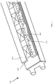
- the radiating elements of base station antennas are connected to the strip lines 112 of the strip line device 110 with coaxial cables 114, wherein the stripe lines 112 are arranged between the cover plate 116 and bottom plate 118 of the strip line device 110.
- the center conductors of the coaxial cable and the strip line are still soldered together, but the coaxial cable braid is also directly soldered to the strip line plates, using special shapes of the plates.
- plates are made from material with good soldering capability (e.g., brass, copper, tin plated steel, etc.).
- EP 1 936 734 A1 discloses a radio frequency circuit module on a multi-layer substrate.
- US 2004/057220 A1 discloses an electronic apparatus provided with a function module such as a sensor and a multilayer circuit board for trunk connecting an output signal wiring of the function module to a coaxial cable.
- US 5 532 659 A discloses a connection of a coaxial cable to a printed circuit.
- JP 2009 290043 A discloses a wiring substrate which can normally operate a mounted electronic component even if highspeed signals are inputted and outputted to the electronic component mounted on the wiring substrate.
- US 2006/255877 A1 discloses signal transmission structure which is at the edge of a circuit board, and the circuit board is connected with a coaxial cable connector through the signal transmission structure.
- the invention provides a system comprising a coaxial cable and a connector for coupling said coaxial cable to a strip line according to claim 1.
- a heat break is created to prevent heat propagation of the solder point of the first solder portion and the braid of the coaxial cable to a huge area and thus the soldering capability between the braid of the coaxial cable and the first plate (e.g., the cover plate of the strip line) could be achieved. Furthermore, as the solder point of the conductor of the strip line and the center conductor of the coaxial cable is exposed, the conductor of the strip line and the center conductor of the coaxial cable could be allowed to be re-soldered without disassembling.
- the degradation of impedance of the coaxial cable to strip line interface occurs, advantageously, a portion, which is under the aperture, of the conductor of the strip line is shaped to compensate impedance degradation caused by the aperture.
- the portion of the conductor of the strip line may be widened to compensate the impedance degradation.
- the aperture is formed over the solder point of the conductor of the strip line and the center conductor of the coaxial cable.
- the first solder portion comprises two solder pads, and the aperture is formed between the two solder pads.
- a second solder portion of a second plate is soldered to the first solder portion of the second plate, the second solder portion having a hole through which the coaxial cable is passed and the braid of the coaxial cable being soldered to the second solder portion.
- the aperture is of rectangle shape.
- the first plate is a cover plate of the strip line, and the first plate is a bottom plate of the strip line.
- the connector for coupling a coaxial cable to a strip line of the invention will be described using the base station antennas as one example of its application scenario; however those skilled in the art could appreciate that the connector can be used in any application scenario where coaxial cables and strip lines are used.
- the exemplary connector 200 of the invention includes a first plate 210 having a first solder portion 212 and an aperture 214 formed adjacent to the first solder portion 212.
- the first plate 210 may be a portion of the cover plate of the strip line, or be the entire cover plate of the strip line, for example.
- the first plate 212 may be a separate part to be mounted on the cover plate of the strip line.
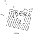
- the first solder portion 212 can be of any suitable configuration, but generally include two solder pads 212a and 212b, and the aperture 214 is typically formed between the two solder pads 212a and 212b, as shown in FIG. 2a .
- the conductor 220 of the strip line is arranged between the first plate 212 (e.g. the cover plate of the strip line) and the second plate 230 (e.g. the bottom plate of the strip line).
- the second solder portion 232 of the second plate 230 is soldered to the first solder portion 212 of the first plate 210 and also has a hole (not shown) formed thereon for the coaxial cable to pass therethrough.
- the coaxial cable 240 passes through the hole of the second solder portion 232 with its braid 242 soldered to the second solder portion 232 and its center conductor 244 soldered to the conductor 220 of the strip line.
- the aperture 214 may be formed over the solder point 252 of the conductor 220 of the strip line and the center conductor 244 of the coaxial cable 240 to expose the solder point 252.
- the conductor 220 of the strip line and the center conductor 244 of the coaxial cable 240 could be allowed to be re-soldered without disassembling.
- the aperture 214 may be of any suitable shape, for example, rectangle, circle, ellipse, trapezium, triangle, etc. Moreover, to consider that the radiation of the aperture 214 could be negligible at the operating frequency, the biggest dimension of the aperture 214 is shaped to be less than 5% of the highest frequency wavelength of the base station antennas.
- the degradation of impedance of the coaxial cable to strip line interface occurs, for example the return loss is degraded to 23dB as shown in FIG. 4 , which is 10 dB degradation compared to the conventional configuration without aperture as shown in FIG. 3 (33 dB, HFSS simulation results).
- a portion 262, which is under the aperture 214, of the conductor 220 of the strip line is shaped to compensate impedance degradation caused by the aperture.
- the portion of the conductor 220 of the strip line may be widened to compensate the impedance degradation. With proper optimization of the shape of the conductor 220 of the strip line, it is possible to obtain good impedance for the coaxial cable to strip line interface with return loss better than 35 dB, as shown in FIG. 5 .
Landscapes
- Coupling Device And Connection With Printed Circuit (AREA)
- Multi-Conductor Connections (AREA)
- Waveguide Aerials (AREA)
Description
- The present invention relates to a system comprising a coaxial cable and a connector according to claim 1.
- Base station antennas are built with arrays of several radiating elements, which are connected to a distribution network (e.g., power dividers, phase shifters, etc.) with transmission lines. Typically, the transmission lines are coaxial cables, and the distribution network are made with strip line devices due to high performances of the strip lines (e.g., good insertion losses, reasonable dimensions, good shielding of the lines, etc.). Specifically, referring to
FIG. 1 , the radiating elements of base station antennas are connected to thestrip lines 112 of thestrip line device 110 withcoaxial cables 114, wherein thestripe lines 112 are arranged between thecover plate 116 andbottom plate 118 of thestrip line device 110. - Several configurations of coaxial cable to strip line interfaces already exist, which mainly comprises two families:
In the first family, the center conductor of the coaxial cable is soldered to the strip line conductor. The braid of the coaxial cable is soldered on an interface part. This interface part is connected to the strip line cover and bottom plates using screws or studs with nuts assemblies. For this family, the potential problems with the interface are: - PIM (Passive Inter Modulation) level variation with screws torque stability;
- If there is a problem in the contact with center conductors of the coaxial cable and strip line, the strip line cover must be removed to be able to repair, for example, to check or re-solder the center conductors.
- In the second family, to remove the PIM potential problems due to screws torque variation, the center conductors of the coaxial cable and the strip line are still soldered together, but the coaxial cable braid is also directly soldered to the strip line plates, using special shapes of the plates. In this case, plates are made from material with good soldering capability (e.g., brass, copper, tin plated steel, etc.). For this family, the problems linked to the configuration are:
- Difficulties to obtain a good solder with the plates due to heat diffusion across huge area around soldering point;
- If there is a problem with the solder of the center conductors, the cover must be removed to repair. As all connection points are soldered, it is even harder to remove the cover than in the first family where it was screwed. Generally, the unsoldered cover has big deformations and must be scrapped and replaced, which is additional cost in labor time and material.
-
EP 1 936 734 A1 discloses a radio frequency circuit module on a multi-layer substrate. -
US 2004/057220 A1 discloses an electronic apparatus provided with a function module such as a sensor and a multilayer circuit board for trunk connecting an output signal wiring of the function module to a coaxial cable. -
US 5 532 659 A discloses a connection of a coaxial cable to a printed circuit. -
JP 2009 290043 A -
US 2006/255877 A1 discloses signal transmission structure which is at the edge of a circuit board, and the circuit board is connected with a coaxial cable connector through the signal transmission structure. - Based on above concerns, it would be advantageous to achieve a connector for coupling a coaxial cable to a strip line, which could improve soldering capability between the braid of the coaxial cable and the cover plate of the strip line and allow the conductor of the strip line and the center conductor of the coaxial cable to be re-soldered without disassembling.
- The invention provides a system comprising a coaxial cable and a connector for coupling said coaxial cable to a strip line according to claim 1.
- With the aperture formed adjacent to the first solder portion, a heat break is created to prevent heat propagation of the solder point of the first solder portion and the braid of the coaxial cable to a huge area and thus the soldering capability between the braid of the coaxial cable and the first plate (e.g., the cover plate of the strip line) could be achieved. Furthermore, as the solder point of the conductor of the strip line and the center conductor of the coaxial cable is exposed, the conductor of the strip line and the center conductor of the coaxial cable could be allowed to be re-soldered without disassembling.
- With the aperture formed on the first plate (e.g., the cover plate of the strip line), the degradation of impedance of the coaxial cable to strip line interface occurs, advantageously, a portion, which is under the aperture, of the conductor of the strip line is shaped to compensate impedance degradation caused by the aperture. For example, the portion of the conductor of the strip line may be widened to compensate the impedance degradation.
- Advantageously, the aperture is formed over the solder point of the conductor of the strip line and the center conductor of the coaxial cable.
- Advantageously, the first solder portion comprises two solder pads, and the aperture is formed between the two solder pads.
- Advantageously, a second solder portion of a second plate is soldered to the first solder portion of the second plate, the second solder portion having a hole through which the coaxial cable is passed and the braid of the coaxial cable being soldered to the second solder portion.
- Advantageously, the aperture is of rectangle shape.
- Advantageously, the first plate is a cover plate of the strip line, and the first plate is a bottom plate of the strip line.
- The above and other objects and features of the present invention will become more apparent from the following detailed description considered in connection with the accompanying drawings, in which:
-
FIG. 1 shows an isometric view of a strip line device with coaxial cable connected to the strip line; -
FIG. 2a shows an isometric view of a first plate according to one embodiment of the invention; -
FIG. 2b shows an isometric view of a first plate with coaxial cable connected to the strip line according to one embodiment of the invention; -
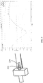
FIG. 3 shows a schematic view of a coaxial cable to strip line interface without aperture and its return loss; -
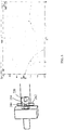
FIG. 4 shows a schematic view of a coaxial cable to strip line interface with aperture and its return loss; and -
FIG. 5 shows a schematic view of a coaxial cable to strip line interface with aperture and compensation and its return loss. - Throughout the above drawings, like reference numerals will be understood to refer to like, similar or corresponding features or functions.
- In the following detailed description of the preferred embodiments, reference is made to the accompanying drawings that form a part hereof. The accompanying drawings show, by way of illustration, specific embodiments in which the disclosure may be practiced. The illustrated embodiments are not intended to be exhaustive of all embodiments according to the disclosure. It is to be understood that other embodiments may be utilized, and structural or logical changes may be made without departing from the scope of the disclosure. The following detailed description, therefore, is not to be taken in a limiting sense, and the scope of the invention is defined by the appended claims.
- In the following Detailed Description, reference is made to the accompanying drawings, which form a part hereof, and in which is shown by way of illustration specific embodiments in which the invention may be practiced. In this regard, directional terminology, such as "left", "right", "top," "bottom," "front," "back," "leading," "forward," "trailing," etc., is used with reference to the orientation of the Figure(s) being described. Because components of embodiments of the present invention can be positioned in a number of different orientations, the directional terminology is used for purposes of illustration and is in no way limiting. It is to be understood that other embodiments may be utilized and structural or logical changes may be made without departing from the scope of the present invention. The following detailed description, therefore, is not to be taken in a limiting sense, and the scope of the present invention is defined by the appended claims.
- Hereinafter, for illustrative purposes only, the connector for coupling a coaxial cable to a strip line of the invention will be described using the base station antennas as one example of its application scenario; however those skilled in the art could appreciate that the connector can be used in any application scenario where coaxial cables and strip lines are used.
- Referring to
FIGs. 2a and2b , theexemplary connector 200 of the invention includes afirst plate 210 having afirst solder portion 212 and anaperture 214 formed adjacent to thefirst solder portion 212. Thefirst plate 210 may be a portion of the cover plate of the strip line, or be the entire cover plate of the strip line, for example. In an alternative example, thefirst plate 212 may be a separate part to be mounted on the cover plate of the strip line. - The
first solder portion 212 can be of any suitable configuration, but generally include twosolder pads aperture 214 is typically formed between the twosolder pads FIG. 2a . - Still referring to
FIG. 2b , theconductor 220 of the strip line is arranged between the first plate 212 (e.g. the cover plate of the strip line) and the second plate 230 (e.g. the bottom plate of the strip line). Thesecond solder portion 232 of thesecond plate 230 is soldered to thefirst solder portion 212 of thefirst plate 210 and also has a hole (not shown) formed thereon for the coaxial cable to pass therethrough. During the assembly, thecoaxial cable 240 passes through the hole of thesecond solder portion 232 with itsbraid 242 soldered to thesecond solder portion 232 and itscenter conductor 244 soldered to theconductor 220 of the strip line. - Since the
aperture 214 is formed adjacent to thefirst solder portion 212, a heat break is created to prevent heat propagation of thesolder point 254 of thefirst solder portion 212 of the cover plate of the strip line and thebraid 242 of the coaxial cable (and thus thesecond solder portion 232 of the bottom plate of the strip line) to a huge area and thus the soldering capability between the braid of the coaxial cable and the cover plate of the strip line could be achieved. - Advantageously, the
aperture 214 may be formed over thesolder point 252 of theconductor 220 of the strip line and thecenter conductor 244 of thecoaxial cable 240 to expose thesolder point 252. As such, theconductor 220 of the strip line and thecenter conductor 244 of thecoaxial cable 240 could be allowed to be re-soldered without disassembling. - To achieve the purpose of preventing heat propagation of the
solder point 254 and exposing thesolder point 252 for re-soldering, theaperture 214 may be of any suitable shape, for example, rectangle, circle, ellipse, trapezium, triangle, etc. Moreover, to consider that the radiation of theaperture 214 could be negligible at the operating frequency, the biggest dimension of theaperture 214 is shaped to be less than 5% of the highest frequency wavelength of the base station antennas. - With the
aperture 214 formed on the cover plate of the strip line, the degradation of impedance of the coaxial cable to strip line interface occurs, for example the return loss is degraded to 23dB as shown inFIG. 4 , which is 10 dB degradation compared to the conventional configuration without aperture as shown inFIG. 3 (33 dB, HFSS simulation results). In this regard, advantageously, aportion 262, which is under theaperture 214, of theconductor 220 of the strip line is shaped to compensate impedance degradation caused by the aperture. For example, the portion of theconductor 220 of the strip line may be widened to compensate the impedance degradation. With proper optimization of the shape of theconductor 220 of the strip line, it is possible to obtain good impedance for the coaxial cable to strip line interface with return loss better than 35 dB, as shown inFIG. 5 . - It should be noted that the above described embodiments are given for describing rather than limiting the invention, and it is to be understood that modifications and variations may be resorted to without departing from the scope of the invention as those skilled in the art readily understand. Such modifications and variations are considered to be within the scope of the invention and the appended claims. The protection scope of the invention is defined by the accompanying claims. In addition, any of the reference numerals in the claims should not be interpreted as a limitation to the claims. Use of the verb "comprise" and its conjugations does not exclude the presence of elements or steps other than those stated in a claim. The indefinite article "a" or "an" preceding an element or step does not exclude the presence of a plurality of such elements or steps.
Claims (9)
- A system comprising a coaxial cable (240) and a connector (200) for coupling said coaxial cable (240) to a strip line, the connector (200) comprising: a first plate (210) to be arranged above a conductor of the strip line to which a center conductor (244) of the coaxial cable (240) is soldered, the first plate (210) including: a first solder portion (212) to which a braid (242) of the coaxial cable is soldered; and an aperture (214) formed adjacent to the first solder portion (212), configured to prevent heat propagation of a solder point of the first solder portion (212) and the braid (242) of the coaxial cable (240) and to expose a solder point of the conductor (220) of the strip line and the center conductor (244) of the coaxial cable (240), wherein the biggest dimension of the aperture (214) is shaped to be less than 5% of the highest frequency wavelength of said coaxial cable (240).
- The system of claim 1, further comprising the conductor (220) of the strip line, wherein a portion (262), which is under the aperture (214), of the conductor (220) of the strip line is shaped to compensate impedance degradation caused by the aperture (214).
- The system of claim 2, wherein the portion (262) of the conductor (220) of the strip line is widened to compensate the impedance degradation.
- The system of claim 1, wherein the aperture (214) is formed over the solder point of the conductor (220) of the strip line and the center conductor (244) of the coaxial cable (240) .
- The system of claim 1, wherein the first solder portion comprises two solder pads (212a, 212b), and the aperture (214) is formed between the two solder pads (212a, 212b).
- The system of claim 1, wherein a second solder portion (232) of a second plate (230) is soldered to the first solder portion (212) of the first plate (210), the second solder portion (232) having a hole through which the coaxial cable (240) is passed and the braid (242) of the coaxial cable (240) being soldered to the second solder portion (232).
- The system of claim 1, wherein the aperture (214) is of rectangle shape.
- The system of claim 1, wherein the first plate (210) is a cover plate of the strip line.
- The system of claim 6, wherein the second plate (230) is a bottom plate of the strip line.
Applications Claiming Priority (2)
| Application Number | Priority Date | Filing Date | Title |
|---|---|---|---|
| CN201310659556.7A CN103647127B (en) | 2013-12-09 | 2013-12-09 | Connector used for coupling coaxial cable to strip line |
| PCT/CN2014/092264 WO2015085865A1 (en) | 2013-12-09 | 2014-11-26 | Connector for coupling coaxial cable to strip line |
Publications (3)
| Publication Number | Publication Date |
|---|---|
| EP3080864A1 EP3080864A1 (en) | 2016-10-19 |
| EP3080864A4 EP3080864A4 (en) | 2017-07-26 |
| EP3080864B1 true EP3080864B1 (en) | 2020-04-08 |
Family
ID=50252316
Family Applications (1)
| Application Number | Title | Priority Date | Filing Date |
|---|---|---|---|
| EP14870409.1A Active EP3080864B1 (en) | 2013-12-09 | 2014-11-26 | System comprising a coaxial cable and a connector for coupling said coaxial cable to a strip line |
Country Status (6)
| Country | Link |
|---|---|
| US (1) | US9871307B2 (en) |
| EP (1) | EP3080864B1 (en) |
| JP (1) | JP6306709B2 (en) |
| KR (1) | KR101861939B1 (en) |
| CN (1) | CN103647127B (en) |
| WO (1) | WO2015085865A1 (en) |
Families Citing this family (4)
| Publication number | Priority date | Publication date | Assignee | Title |
|---|---|---|---|---|
| CN103647127B (en) | 2013-12-09 | 2017-02-01 | 上海贝尔股份有限公司 | Connector used for coupling coaxial cable to strip line |
| DE102016125897B4 (en) * | 2016-02-11 | 2022-06-23 | Few Fahrzeugelektrikwerk Gmbh & Co. Kg | Solderable electrical connection element |
| US12068520B2 (en) * | 2019-07-03 | 2024-08-20 | Kabushiki Kaisha Toshiba | Coaxial microstrip line conversion circuit |
| CN115719892A (en) * | 2021-08-27 | 2023-02-28 | 康普技术有限责任公司 | Connection components for antennas and base station antennas |
Family Cites Families (55)
| Publication number | Priority date | Publication date | Assignee | Title |
|---|---|---|---|---|
| US3553607A (en) * | 1968-02-29 | 1971-01-05 | Tek Wave Inc | Connector for coupling a microwave coaxial circuit to a microstrip printed circuit |
| US3539966A (en) * | 1968-07-23 | 1970-11-10 | Us Army | Microwave connector |
| US3662318A (en) * | 1970-12-23 | 1972-05-09 | Comp Generale Electricite | Transition device between coaxial and microstrip lines |
| US3725829A (en) * | 1971-07-14 | 1973-04-03 | Itek Corp | Electrical connector |
| US4280112A (en) * | 1979-02-21 | 1981-07-21 | Eisenhart Robert L | Electrical coupler |
| DE2949013C2 (en) * | 1979-12-06 | 1985-05-02 | ANT Nachrichtentechnik GmbH, 7150 Backnang | Transition from a coaxial cable to a multi-pin connector |
| US4487999A (en) * | 1983-01-10 | 1984-12-11 | Isotronics, Inc. | Microwave chip carrier |
| US4906957A (en) * | 1986-10-09 | 1990-03-06 | Sanders Associates, Inc. | Electrical circuit interconnect system |
| JPH04116411U (en) * | 1991-03-28 | 1992-10-19 | セントラル硝子株式会社 | Glass antenna connection structure |
| US5402088A (en) | 1992-12-03 | 1995-03-28 | Ail Systems, Inc. | Apparatus for the interconnection of radio frequency (RF) monolithic microwave integrated circuits |
| US5404117A (en) * | 1993-10-01 | 1995-04-04 | Hewlett-Packard Company | Connector for strip-type transmission line to coaxial cable |
| FR2720196B1 (en) * | 1994-05-19 | 1996-06-21 | Thomson Csf | Connection device for ensuring a cable connection on a printed circuit and printed circuit equipped with such a device. |
| JPH08340207A (en) | 1995-04-14 | 1996-12-24 | Sony Corp | Antenna device and portable radio device |
| JPH08293358A (en) * | 1995-04-24 | 1996-11-05 | Dai Ichi Denshi Kogyo Kk | Coaxial cable connector |
| US5613859A (en) * | 1995-11-28 | 1997-03-25 | Watkins-Johnson Company | Connector asembly for detachably connecting a printed wiring board to a coaxial transmission lines connector |
| US5738529A (en) * | 1996-02-29 | 1998-04-14 | Methode Electronics, Inc. | Cable connector system |
| US5823790A (en) * | 1996-07-29 | 1998-10-20 | Lucent Technologies Inc. | Connector for attaching a cable to a printed circuit board |
| TW364685U (en) * | 1997-11-06 | 1999-07-11 | Insert Entpr Co Ltd | Cable connector |
| JP3209183B2 (en) * | 1998-07-08 | 2001-09-17 | 日本電気株式会社 | High frequency signal integrated circuit package and method of manufacturing the same |
| US6126453A (en) | 1998-10-08 | 2000-10-03 | Andrew Corporation | Transmission line terminations and junctions |
| US6356245B2 (en) * | 1999-04-01 | 2002-03-12 | Space Systems/Loral, Inc. | Microwave strip transmission lines, beamforming networks and antennas and methods for preparing the same |
| JP3976473B2 (en) * | 2000-05-09 | 2007-09-19 | 日本電気株式会社 | High frequency circuit and module and communication device using the same |
| CA2438469A1 (en) * | 2001-02-16 | 2002-08-29 | Ems Technologies, Inc. | Method and system for connecting a cable to a circuit board |
| SE520321C2 (en) * | 2001-04-11 | 2003-06-24 | Allgon Ab | PCB plug |
| US6468089B1 (en) * | 2001-04-20 | 2002-10-22 | Molex Incorporated | Solder-less printed circuit board edge connector having a common ground contact for a plurality of transmission lines |
| US6457979B1 (en) * | 2001-10-29 | 2002-10-01 | Agilent Technologies, Inc. | Shielded attachment of coaxial RF connector to thick film integrally shielded transmission line on a substrate |
| DE10158384A1 (en) * | 2001-11-28 | 2003-06-18 | Hirschmann Electronics Gmbh | plug |
| JP3998996B2 (en) * | 2002-03-01 | 2007-10-31 | 凌和電子株式会社 | High frequency transmission line connection system and method |
| US6572407B1 (en) * | 2002-04-05 | 2003-06-03 | Hon Hai Precision Ind. Co., Ltd. | Low profile cable end connector |
| JP4125570B2 (en) * | 2002-09-19 | 2008-07-30 | 日本電気株式会社 | Electronic equipment |
| US6894590B2 (en) | 2003-05-30 | 2005-05-17 | Agilent Technologies, Inc. | Apparatus and method to introduce signals into a shielded RF circuit |
| US7113149B2 (en) * | 2003-09-25 | 2006-09-26 | Radio Frequency Systems, Inc. | Apparatus and method for clamping cables in an antenna |
| JP2005317298A (en) * | 2004-04-28 | 2005-11-10 | Hirose Electric Co Ltd | Coaxial cable terminal and mounting structure and mounting method of the coaxial cable terminal |
| EP1771966A1 (en) | 2004-07-29 | 2007-04-11 | Samsung Electronics Co., Ltd. | Method of transmitting and reproducing content processed by various drm systems |
| KR100636169B1 (en) | 2004-07-29 | 2006-10-18 | 삼성전자주식회사 | Method for transmitting content which is processed by various DRM System, and the method for reproducing the contents |
| TWI290443B (en) | 2005-05-10 | 2007-11-21 | Via Tech Inc | Signal transmission structure, wire board and connector assembly structure |
| US20070054510A1 (en) * | 2005-09-02 | 2007-03-08 | Russell Price | System and method for shielded coaxial cable attachment |
| JP2009021648A (en) * | 2007-07-10 | 2009-01-29 | Kojima Press Co Ltd | Vehicle antenna device and method for connecting antenna element thereof to cable |
| JP4832384B2 (en) * | 2007-08-29 | 2011-12-07 | 矢崎総業株式会社 | Antenna connection structure and antenna connection method |
| US20090059540A1 (en) * | 2007-08-31 | 2009-03-05 | Giboney Kirk S | Shielded high-frequency circuit module |
| AU2009212712A1 (en) * | 2008-02-01 | 2009-08-13 | Raytheon Company | Radio frequency connector |
| JP5370883B2 (en) | 2008-05-30 | 2013-12-18 | 京セラSlcテクノロジー株式会社 | Wiring board |
| US7690922B2 (en) * | 2008-09-04 | 2010-04-06 | Chung-Chuan Huang | Electrical connector |
| US8035466B2 (en) * | 2009-01-12 | 2011-10-11 | Kenneth Ray Payne | High frequency electrical connector |
| FR2942569B1 (en) | 2009-02-25 | 2011-03-25 | Alcatel Lucent | CONNECTING DEVICE FOR A COAXIAL CABLE CARRYING HIGH FREQUENCY SIGNAL. |
| JP5365389B2 (en) | 2009-07-21 | 2013-12-11 | 住友電気工業株式会社 | Coaxial cable harness |
| FR2950200A1 (en) * | 2009-09-11 | 2011-03-18 | Thales Sa | CONNECTING DEVICE FOR HIGH FREQUENCY SIGNALS BETWEEN A CONNECTOR AND A TRANSMISSION LINE |
| CN201629411U (en) * | 2010-01-07 | 2010-11-10 | 摩比天线技术(深圳)有限公司 | Coaxial-cable welding device and printed circuit board |
| CN102208710B (en) * | 2010-03-31 | 2014-11-19 | 安德鲁公司 | RF Coaxial Cable to Air Microstrip Coupling Ground Transition Structure and Corresponding Antenna |
| CN202231185U (en) * | 2011-08-25 | 2012-05-23 | 合肥佰特微波技术有限公司 | Coaxial cable connector with integral outer conductor |
| US8982582B2 (en) * | 2012-11-30 | 2015-03-17 | Apple Inc. | Electronic device with antenna cable bracket |
| CN203225416U (en) | 2013-04-26 | 2013-10-02 | 华为技术有限公司 | Coaxial cable connecting assembly |
| CN103647127B (en) | 2013-12-09 | 2017-02-01 | 上海贝尔股份有限公司 | Connector used for coupling coaxial cable to strip line |
| CN203617413U (en) * | 2013-12-09 | 2014-05-28 | 上海贝尔股份有限公司 | Connector for coupling coaxial cable to strip line |
| US9356366B2 (en) * | 2014-04-24 | 2016-05-31 | Tyco Electronics Corporation | Cable connector assembly for a communication system |
-
2013
- 2013-12-09 CN CN201310659556.7A patent/CN103647127B/en not_active Expired - Fee Related
-
2014
- 2014-11-26 US US15/102,943 patent/US9871307B2/en not_active Expired - Fee Related
- 2014-11-26 WO PCT/CN2014/092264 patent/WO2015085865A1/en not_active Ceased
- 2014-11-26 EP EP14870409.1A patent/EP3080864B1/en active Active
- 2014-11-26 JP JP2016538083A patent/JP6306709B2/en not_active Expired - Fee Related
- 2014-11-26 KR KR1020167017978A patent/KR101861939B1/en not_active Expired - Fee Related
Non-Patent Citations (1)
| Title |
|---|
| None * |
Also Published As
| Publication number | Publication date |
|---|---|
| EP3080864A1 (en) | 2016-10-19 |
| CN103647127B (en) | 2017-02-01 |
| CN103647127A (en) | 2014-03-19 |
| KR20160096139A (en) | 2016-08-12 |
| EP3080864A4 (en) | 2017-07-26 |
| KR101861939B1 (en) | 2018-05-28 |
| JP2017500802A (en) | 2017-01-05 |
| US9871307B2 (en) | 2018-01-16 |
| WO2015085865A1 (en) | 2015-06-18 |
| US20160308291A1 (en) | 2016-10-20 |
| JP6306709B2 (en) | 2018-04-04 |
Similar Documents
| Publication | Publication Date | Title |
|---|---|---|
| KR102479633B1 (en) | Additive Manufacturing Technology (AMT) Faraday Boundaries in Radio Frequency Circuits | |
| CN110167261B (en) | Millimeter wave active antenna unit and PCB board interconnection structure | |
| US8198954B2 (en) | Impedance matched circuit board | |
| US20150351222A1 (en) | Resin multilayer substrate and electronic apparatus | |
| US20170331230A1 (en) | Connector Assembly and Related Methods and Assemblies | |
| US10833461B2 (en) | Connectors for coaxial cables | |
| KR20130054332A (en) | High-frequency signal line and electronic device | |
| US9054404B2 (en) | Multi-layer circuit board with waveguide to microstrip transition structure | |
| US8449305B2 (en) | Mechanical and electric connection device for a coaxial cable conveying a high-frequency signal | |
| CN105914464B (en) | Antenna device | |
| US9871307B2 (en) | Connector for coupling coaxial cable to strip line | |
| US9408306B2 (en) | Antenna array feeding structure having circuit boards connected by at least one solderable pin | |
| KR20180116414A (en) | The flexible printed circuit board structure and the indoor partition wall | |
| CN209329161U (en) | Phase-shifting feeder and base station antenna | |
| EP3249741B1 (en) | Device for the connection between a strip line and a coaxial cable | |
| US10777899B2 (en) | Transmission line coupling system | |
| US11903124B2 (en) | Wide band printed circuit board through connector | |
| KR102459055B1 (en) | improved communication array | |
| CN210579424U (en) | PCB plate structure of Massive MIMO antenna | |
| CN210328147U (en) | Millimeter wave active antenna unit and interconnection structure between PCB boards | |
| US10524354B2 (en) | Electronic device | |
| CN203617413U (en) | Connector for coupling coaxial cable to strip line | |
| JP7245947B1 (en) | Printed wiring boards and wireless communication terminals | |
| EP2988366A1 (en) | Orthogonal modular embedded antenna, with method of manufacture and kits therefor |
Legal Events
| Date | Code | Title | Description |
|---|---|---|---|
| PUAI | Public reference made under article 153(3) epc to a published international application that has entered the european phase |
Free format text: ORIGINAL CODE: 0009012 |
|
| 17P | Request for examination filed |
Effective date: 20160711 |
|
| AK | Designated contracting states |
Kind code of ref document: A1 Designated state(s): AL AT BE BG CH CY CZ DE DK EE ES FI FR GB GR HR HU IE IS IT LI LT LU LV MC MK MT NL NO PL PT RO RS SE SI SK SM TR |
|
| AX | Request for extension of the european patent |
Extension state: BA ME |
|
| DAX | Request for extension of the european patent (deleted) | ||
| A4 | Supplementary search report drawn up and despatched |
Effective date: 20170622 |
|
| RIC1 | Information provided on ipc code assigned before grant |
Ipc: H01R 24/44 20110101ALI20170616BHEP Ipc: H01P 5/08 20060101AFI20170616BHEP Ipc: H01R 4/58 20060101ALI20170616BHEP Ipc: H01R 13/6474 20110101ALI20170616BHEP Ipc: H01R 9/05 20060101ALI20170616BHEP Ipc: H01R 4/02 20060101ALN20170616BHEP Ipc: H01R 12/53 20110101ALN20170616BHEP |
|
| STAA | Information on the status of an ep patent application or granted ep patent |
Free format text: STATUS: EXAMINATION IS IN PROGRESS |
|
| 17Q | First examination report despatched |
Effective date: 20180720 |
|
| GRAP | Despatch of communication of intention to grant a patent |
Free format text: ORIGINAL CODE: EPIDOSNIGR1 |
|
| STAA | Information on the status of an ep patent application or granted ep patent |
Free format text: STATUS: GRANT OF PATENT IS INTENDED |
|
| RIC1 | Information provided on ipc code assigned before grant |
Ipc: H01R 4/58 20060101ALI20190919BHEP Ipc: H01R 24/44 20110101ALI20190919BHEP Ipc: H01R 13/6474 20110101ALI20190919BHEP Ipc: H01R 4/02 20060101ALN20190919BHEP Ipc: H01P 5/08 20060101AFI20190919BHEP Ipc: H01R 9/05 20060101ALI20190919BHEP Ipc: H01R 12/53 20110101ALN20190919BHEP |
|
| RIC1 | Information provided on ipc code assigned before grant |
Ipc: H01R 4/02 20060101ALN20190924BHEP Ipc: H01R 9/05 20060101ALI20190924BHEP Ipc: H01P 5/08 20060101AFI20190924BHEP Ipc: H01R 4/58 20060101ALI20190924BHEP Ipc: H01R 13/6474 20110101ALI20190924BHEP Ipc: H01R 12/53 20110101ALN20190924BHEP Ipc: H01R 24/44 20110101ALI20190924BHEP |
|
| INTG | Intention to grant announced |
Effective date: 20191009 |
|
| RIC1 | Information provided on ipc code assigned before grant |
Ipc: H01R 9/05 20060101ALI20190930BHEP Ipc: H01R 24/44 20110101ALI20190930BHEP Ipc: H01R 4/58 20060101ALI20190930BHEP Ipc: H01R 13/6474 20110101ALI20190930BHEP Ipc: H01P 5/08 20060101AFI20190930BHEP Ipc: H01R 12/53 20110101ALN20190930BHEP Ipc: H01R 4/02 20060101ALN20190930BHEP |
|
| GRAS | Grant fee paid |
Free format text: ORIGINAL CODE: EPIDOSNIGR3 |
|
| GRAA | (expected) grant |
Free format text: ORIGINAL CODE: 0009210 |
|
| STAA | Information on the status of an ep patent application or granted ep patent |
Free format text: STATUS: THE PATENT HAS BEEN GRANTED |
|
| AK | Designated contracting states |
Kind code of ref document: B1 Designated state(s): AL AT BE BG CH CY CZ DE DK EE ES FI FR GB GR HR HU IE IS IT LI LT LU LV MC MK MT NL NO PL PT RO RS SE SI SK SM TR |
|
| RAP1 | Party data changed (applicant data changed or rights of an application transferred) |
Owner name: NOKIA SHANGHAI BELL CO., LTD. |
|
| REG | Reference to a national code |
Ref country code: CH Ref legal event code: EP Ref country code: AT Ref legal event code: REF Ref document number: 1255597 Country of ref document: AT Kind code of ref document: T Effective date: 20200415 |
|
| REG | Reference to a national code |
Ref country code: DE Ref legal event code: R096 Ref document number: 602014063644 Country of ref document: DE |
|
| REG | Reference to a national code |
Ref country code: IE Ref legal event code: FG4D |
|
| REG | Reference to a national code |
Ref country code: NL Ref legal event code: MP Effective date: 20200408 |
|
| REG | Reference to a national code |
Ref country code: LT Ref legal event code: MG4D |
|
| PG25 | Lapsed in a contracting state [announced via postgrant information from national office to epo] |
Ref country code: SE Free format text: LAPSE BECAUSE OF FAILURE TO SUBMIT A TRANSLATION OF THE DESCRIPTION OR TO PAY THE FEE WITHIN THE PRESCRIBED TIME-LIMIT Effective date: 20200408 Ref country code: NL Free format text: LAPSE BECAUSE OF FAILURE TO SUBMIT A TRANSLATION OF THE DESCRIPTION OR TO PAY THE FEE WITHIN THE PRESCRIBED TIME-LIMIT Effective date: 20200408 Ref country code: LT Free format text: LAPSE BECAUSE OF FAILURE TO SUBMIT A TRANSLATION OF THE DESCRIPTION OR TO PAY THE FEE WITHIN THE PRESCRIBED TIME-LIMIT Effective date: 20200408 Ref country code: PT Free format text: LAPSE BECAUSE OF FAILURE TO SUBMIT A TRANSLATION OF THE DESCRIPTION OR TO PAY THE FEE WITHIN THE PRESCRIBED TIME-LIMIT Effective date: 20200817 Ref country code: FI Free format text: LAPSE BECAUSE OF FAILURE TO SUBMIT A TRANSLATION OF THE DESCRIPTION OR TO PAY THE FEE WITHIN THE PRESCRIBED TIME-LIMIT Effective date: 20200408 Ref country code: NO Free format text: LAPSE BECAUSE OF FAILURE TO SUBMIT A TRANSLATION OF THE DESCRIPTION OR TO PAY THE FEE WITHIN THE PRESCRIBED TIME-LIMIT Effective date: 20200708 Ref country code: GR Free format text: LAPSE BECAUSE OF FAILURE TO SUBMIT A TRANSLATION OF THE DESCRIPTION OR TO PAY THE FEE WITHIN THE PRESCRIBED TIME-LIMIT Effective date: 20200709 Ref country code: IS Free format text: LAPSE BECAUSE OF FAILURE TO SUBMIT A TRANSLATION OF THE DESCRIPTION OR TO PAY THE FEE WITHIN THE PRESCRIBED TIME-LIMIT Effective date: 20200808 |
|
| REG | Reference to a national code |
Ref country code: AT Ref legal event code: MK05 Ref document number: 1255597 Country of ref document: AT Kind code of ref document: T Effective date: 20200408 |
|
| PG25 | Lapsed in a contracting state [announced via postgrant information from national office to epo] |
Ref country code: LV Free format text: LAPSE BECAUSE OF FAILURE TO SUBMIT A TRANSLATION OF THE DESCRIPTION OR TO PAY THE FEE WITHIN THE PRESCRIBED TIME-LIMIT Effective date: 20200408 Ref country code: HR Free format text: LAPSE BECAUSE OF FAILURE TO SUBMIT A TRANSLATION OF THE DESCRIPTION OR TO PAY THE FEE WITHIN THE PRESCRIBED TIME-LIMIT Effective date: 20200408 Ref country code: RS Free format text: LAPSE BECAUSE OF FAILURE TO SUBMIT A TRANSLATION OF THE DESCRIPTION OR TO PAY THE FEE WITHIN THE PRESCRIBED TIME-LIMIT Effective date: 20200408 Ref country code: BG Free format text: LAPSE BECAUSE OF FAILURE TO SUBMIT A TRANSLATION OF THE DESCRIPTION OR TO PAY THE FEE WITHIN THE PRESCRIBED TIME-LIMIT Effective date: 20200708 |
|
| PG25 | Lapsed in a contracting state [announced via postgrant information from national office to epo] |
Ref country code: AL Free format text: LAPSE BECAUSE OF FAILURE TO SUBMIT A TRANSLATION OF THE DESCRIPTION OR TO PAY THE FEE WITHIN THE PRESCRIBED TIME-LIMIT Effective date: 20200408 |
|
| REG | Reference to a national code |
Ref country code: DE Ref legal event code: R097 Ref document number: 602014063644 Country of ref document: DE |
|
| PG25 | Lapsed in a contracting state [announced via postgrant information from national office to epo] |
Ref country code: RO Free format text: LAPSE BECAUSE OF FAILURE TO SUBMIT A TRANSLATION OF THE DESCRIPTION OR TO PAY THE FEE WITHIN THE PRESCRIBED TIME-LIMIT Effective date: 20200408 Ref country code: CZ Free format text: LAPSE BECAUSE OF FAILURE TO SUBMIT A TRANSLATION OF THE DESCRIPTION OR TO PAY THE FEE WITHIN THE PRESCRIBED TIME-LIMIT Effective date: 20200408 Ref country code: ES Free format text: LAPSE BECAUSE OF FAILURE TO SUBMIT A TRANSLATION OF THE DESCRIPTION OR TO PAY THE FEE WITHIN THE PRESCRIBED TIME-LIMIT Effective date: 20200408 Ref country code: DK Free format text: LAPSE BECAUSE OF FAILURE TO SUBMIT A TRANSLATION OF THE DESCRIPTION OR TO PAY THE FEE WITHIN THE PRESCRIBED TIME-LIMIT Effective date: 20200408 Ref country code: SM Free format text: LAPSE BECAUSE OF FAILURE TO SUBMIT A TRANSLATION OF THE DESCRIPTION OR TO PAY THE FEE WITHIN THE PRESCRIBED TIME-LIMIT Effective date: 20200408 Ref country code: IT Free format text: LAPSE BECAUSE OF FAILURE TO SUBMIT A TRANSLATION OF THE DESCRIPTION OR TO PAY THE FEE WITHIN THE PRESCRIBED TIME-LIMIT Effective date: 20200408 Ref country code: AT Free format text: LAPSE BECAUSE OF FAILURE TO SUBMIT A TRANSLATION OF THE DESCRIPTION OR TO PAY THE FEE WITHIN THE PRESCRIBED TIME-LIMIT Effective date: 20200408 Ref country code: EE Free format text: LAPSE BECAUSE OF FAILURE TO SUBMIT A TRANSLATION OF THE DESCRIPTION OR TO PAY THE FEE WITHIN THE PRESCRIBED TIME-LIMIT Effective date: 20200408 |
|
| PLBE | No opposition filed within time limit |
Free format text: ORIGINAL CODE: 0009261 |
|
| STAA | Information on the status of an ep patent application or granted ep patent |
Free format text: STATUS: NO OPPOSITION FILED WITHIN TIME LIMIT |
|
| PG25 | Lapsed in a contracting state [announced via postgrant information from national office to epo] |
Ref country code: PL Free format text: LAPSE BECAUSE OF FAILURE TO SUBMIT A TRANSLATION OF THE DESCRIPTION OR TO PAY THE FEE WITHIN THE PRESCRIBED TIME-LIMIT Effective date: 20200408 Ref country code: SK Free format text: LAPSE BECAUSE OF FAILURE TO SUBMIT A TRANSLATION OF THE DESCRIPTION OR TO PAY THE FEE WITHIN THE PRESCRIBED TIME-LIMIT Effective date: 20200408 |
|
| 26N | No opposition filed |
Effective date: 20210112 |
|
| PG25 | Lapsed in a contracting state [announced via postgrant information from national office to epo] |
Ref country code: SI Free format text: LAPSE BECAUSE OF FAILURE TO SUBMIT A TRANSLATION OF THE DESCRIPTION OR TO PAY THE FEE WITHIN THE PRESCRIBED TIME-LIMIT Effective date: 20200408 |
|
| PG25 | Lapsed in a contracting state [announced via postgrant information from national office to epo] |
Ref country code: MC Free format text: LAPSE BECAUSE OF FAILURE TO SUBMIT A TRANSLATION OF THE DESCRIPTION OR TO PAY THE FEE WITHIN THE PRESCRIBED TIME-LIMIT Effective date: 20200408 |
|
| REG | Reference to a national code |
Ref country code: CH Ref legal event code: PL |
|
| PG25 | Lapsed in a contracting state [announced via postgrant information from national office to epo] |
Ref country code: LU Free format text: LAPSE BECAUSE OF NON-PAYMENT OF DUE FEES Effective date: 20201126 |
|
| REG | Reference to a national code |
Ref country code: BE Ref legal event code: MM Effective date: 20201130 |
|
| PG25 | Lapsed in a contracting state [announced via postgrant information from national office to epo] |
Ref country code: CH Free format text: LAPSE BECAUSE OF NON-PAYMENT OF DUE FEES Effective date: 20201130 Ref country code: LI Free format text: LAPSE BECAUSE OF NON-PAYMENT OF DUE FEES Effective date: 20201130 |
|
| PG25 | Lapsed in a contracting state [announced via postgrant information from national office to epo] |
Ref country code: FR Free format text: LAPSE BECAUSE OF NON-PAYMENT OF DUE FEES Effective date: 20201130 Ref country code: IE Free format text: LAPSE BECAUSE OF NON-PAYMENT OF DUE FEES Effective date: 20201126 |
|
| PG25 | Lapsed in a contracting state [announced via postgrant information from national office to epo] |
Ref country code: TR Free format text: LAPSE BECAUSE OF FAILURE TO SUBMIT A TRANSLATION OF THE DESCRIPTION OR TO PAY THE FEE WITHIN THE PRESCRIBED TIME-LIMIT Effective date: 20200408 Ref country code: MT Free format text: LAPSE BECAUSE OF FAILURE TO SUBMIT A TRANSLATION OF THE DESCRIPTION OR TO PAY THE FEE WITHIN THE PRESCRIBED TIME-LIMIT Effective date: 20200408 Ref country code: CY Free format text: LAPSE BECAUSE OF FAILURE TO SUBMIT A TRANSLATION OF THE DESCRIPTION OR TO PAY THE FEE WITHIN THE PRESCRIBED TIME-LIMIT Effective date: 20200408 |
|
| PG25 | Lapsed in a contracting state [announced via postgrant information from national office to epo] |
Ref country code: MK Free format text: LAPSE BECAUSE OF FAILURE TO SUBMIT A TRANSLATION OF THE DESCRIPTION OR TO PAY THE FEE WITHIN THE PRESCRIBED TIME-LIMIT Effective date: 20200408 |
|
| PG25 | Lapsed in a contracting state [announced via postgrant information from national office to epo] |
Ref country code: BE Free format text: LAPSE BECAUSE OF NON-PAYMENT OF DUE FEES Effective date: 20201130 |
|
| PGFP | Annual fee paid to national office [announced via postgrant information from national office to epo] |
Ref country code: GB Payment date: 20231127 Year of fee payment: 10 |
|
| PGFP | Annual fee paid to national office [announced via postgrant information from national office to epo] |
Ref country code: DE Payment date: 20231129 Year of fee payment: 10 |
|
| REG | Reference to a national code |
Ref country code: DE Ref legal event code: R119 Ref document number: 602014063644 Country of ref document: DE |
|
| GBPC | Gb: european patent ceased through non-payment of renewal fee |
Effective date: 20241126 |
|
| PG25 | Lapsed in a contracting state [announced via postgrant information from national office to epo] |
Ref country code: DE Free format text: LAPSE BECAUSE OF NON-PAYMENT OF DUE FEES Effective date: 20250603 |
|
| PG25 | Lapsed in a contracting state [announced via postgrant information from national office to epo] |
Ref country code: GB Free format text: LAPSE BECAUSE OF NON-PAYMENT OF DUE FEES Effective date: 20241126 |