EP3079914B1 - Printing blanket with non-extensible backing mountable in a single reel rod lock-up - Google Patents
Printing blanket with non-extensible backing mountable in a single reel rod lock-up Download PDFInfo
- Publication number
- EP3079914B1 EP3079914B1 EP14758244.9A EP14758244A EP3079914B1 EP 3079914 B1 EP3079914 B1 EP 3079914B1 EP 14758244 A EP14758244 A EP 14758244A EP 3079914 B1 EP3079914 B1 EP 3079914B1
- Authority
- EP
- European Patent Office
- Prior art keywords
- blanket
- printing
- gap
- trail
- cylinder
- Prior art date
- Legal status (The legal status is an assumption and is not a legal conclusion. Google has not performed a legal analysis and makes no representation as to the accuracy of the status listed.)
- Active
Links
Images


Classifications
-
- B—PERFORMING OPERATIONS; TRANSPORTING
- B41—PRINTING; LINING MACHINES; TYPEWRITERS; STAMPS
- B41F—PRINTING MACHINES OR PRESSES
- B41F30/00—Devices for attaching coverings or make-ready devices; Guiding devices for coverings
- B41F30/04—Devices for attaching coverings or make-ready devices; Guiding devices for coverings attaching to transfer cylinders
-
- B—PERFORMING OPERATIONS; TRANSPORTING
- B41—PRINTING; LINING MACHINES; TYPEWRITERS; STAMPS
- B41F—PRINTING MACHINES OR PRESSES
- B41F27/00—Devices for attaching printing elements or formes to supports
- B41F27/12—Devices for attaching printing elements or formes to supports for attaching flexible printing formes
- B41F27/1218—Devices for attaching printing elements or formes to supports for attaching flexible printing formes comprising printing plate tensioning devices
- B41F27/125—Devices for attaching printing elements or formes to supports for attaching flexible printing formes comprising printing plate tensioning devices moving in the printing plate end on a curvilinear path, e.g. by winding on a roll
-
- B—PERFORMING OPERATIONS; TRANSPORTING
- B41—PRINTING; LINING MACHINES; TYPEWRITERS; STAMPS
- B41N—PRINTING PLATES OR FOILS; MATERIALS FOR SURFACES USED IN PRINTING MACHINES FOR PRINTING, INKING, DAMPING, OR THE LIKE; PREPARING SUCH SURFACES FOR USE AND CONSERVING THEM
- B41N10/00—Blankets or like coverings; Coverings for wipers for intaglio printing
- B41N10/02—Blanket structure
- B41N10/06—Blanket structure facilitating fastening to, or location on, supports
-
- B—PERFORMING OPERATIONS; TRANSPORTING
- B41—PRINTING; LINING MACHINES; TYPEWRITERS; STAMPS
- B41F—PRINTING MACHINES OR PRESSES
- B41F27/00—Devices for attaching printing elements or formes to supports
- B41F27/12—Devices for attaching printing elements or formes to supports for attaching flexible printing formes
-
- B—PERFORMING OPERATIONS; TRANSPORTING
- B41—PRINTING; LINING MACHINES; TYPEWRITERS; STAMPS
- B41N—PRINTING PLATES OR FOILS; MATERIALS FOR SURFACES USED IN PRINTING MACHINES FOR PRINTING, INKING, DAMPING, OR THE LIKE; PREPARING SUCH SURFACES FOR USE AND CONSERVING THEM
- B41N10/00—Blankets or like coverings; Coverings for wipers for intaglio printing
- B41N10/02—Blanket structure
-
- B—PERFORMING OPERATIONS; TRANSPORTING
- B41—PRINTING; LINING MACHINES; TYPEWRITERS; STAMPS
- B41N—PRINTING PLATES OR FOILS; MATERIALS FOR SURFACES USED IN PRINTING MACHINES FOR PRINTING, INKING, DAMPING, OR THE LIKE; PREPARING SUCH SURFACES FOR USE AND CONSERVING THEM
- B41N10/00—Blankets or like coverings; Coverings for wipers for intaglio printing
- B41N10/02—Blanket structure
- B41N10/04—Blanket structure multi-layer
-
- B—PERFORMING OPERATIONS; TRANSPORTING
- B41—PRINTING; LINING MACHINES; TYPEWRITERS; STAMPS
- B41N—PRINTING PLATES OR FOILS; MATERIALS FOR SURFACES USED IN PRINTING MACHINES FOR PRINTING, INKING, DAMPING, OR THE LIKE; PREPARING SUCH SURFACES FOR USE AND CONSERVING THEM
- B41N2210/00—Location or type of the layers in multi-layer blankets or like coverings
- B41N2210/06—Backcoats; Back layers; Bottom layers
-
- B—PERFORMING OPERATIONS; TRANSPORTING
- B41—PRINTING; LINING MACHINES; TYPEWRITERS; STAMPS
- B41N—PRINTING PLATES OR FOILS; MATERIALS FOR SURFACES USED IN PRINTING MACHINES FOR PRINTING, INKING, DAMPING, OR THE LIKE; PREPARING SUCH SURFACES FOR USE AND CONSERVING THEM
- B41N2210/00—Location or type of the layers in multi-layer blankets or like coverings
- B41N2210/10—Location or type of the layers in multi-layer blankets or like coverings characterised by inorganic compounds, e.g. pigments
Definitions
- the use of a metal backing is often preferable as it prevents stretching of the blanket when it is mounted on the blanket cylinder.
- the metal backing also provides dimensional stability to the blanket, resulting in high print quality, eliminates the need for frequent re-tensioning of the blanket as would be required with conventional fabric-backed blankets and improves printing to the edge of the blanket cylinder gap.
- the printing blanket includes one or more compressible plies positioned beneath the printing surface layer, and at least one reinforcing ply comprised of fabric, non-wovens, or polymeric materials positioned beneath said printing surface layer.
- the non-extensible backing layer comprises a metal or metal alloy, polymer, or other suitable non-extensible material in the form of a relatively thin sheet.
- Figs. 1 and 2 illustrate a conventional blanket cylinder 10 having a conventional fabric-backed printing blanket 12 to be mounted thereon using a single reel rod lockup mechanism 14.
- Blanket 12 includes at least a print surface layer and a reinforcing fabric backing ply.
- Conventional printing blankets may also include additional plies or layers (not shown) as is well known in the art.
- Lead and trail blanket bars 13 and 15 are secured to opposite ends of the blanket.
- a blanket bar is typically formed from metal and is used to reinforce the ends of a printing blanket and as an aid in inserting and securing the blanket ends in the lock-up mechanism.
- the non-extensible backing layer 38 preferably comprises a flexible, but non-extensible material such as a thin metal or metal alloy sheet or other non-extensible material such as a polymeric material.
- a preferred material for backing layer 38 is stainless steel having a thickness of from between about 0.006 to about 0.010 inches (about 0.15 to about 0.25 mm), which material is readily commercially available. Other materials may be used, so long as they are substantially non-extensible in use under normal operating conditions and so long as they have sufficient flexibility to be mounted onto conventional blanket cylinders.
- Woven fabric ply 36 may be partially or entirely ground to adjust the thickness thereof.
- Fabric plies 33 and 36 have thicknesses, respectively, preferably in a range from about 0.008 to about 0.016 inches (from about 0.20 to about 0.4 mm) and most preferably, a thickness of about 0.011 inches (0.28 mm).
- Reinforcing plies 33 and 36 can comprise fabrics woven from cotton or synthetic yarns or fibers having both warp and weft fibers or yarns.
- One preferred fabric for use in the present invention is a square woven fabric in which the warp yarns are cotton (such as, for example, pima cotton) and the weft yarns are polyester (such as a spun polyester). The fabric is pre-stretched in a single direction along the length of the warp yarns such that the fabric as used in the manufacture of the image transfer blanket has little or no residual stretch in that direction.
- any known compressible or resilient material compatible with the other plies may be used in accordance with embodiments of the invention.
- a preferred compressible layer 34 comprises a blend of nitrile and chloroprene-based rubber having a pore density to provide adequate strength and compressibility.
- Compressible layer 34 may comprise either open or closed-cell foam, with closed cell foams being preferred.
- Suitable compressible layer materials and their methods of fabrication include those materials disclosed in commonly-assigned U.S. Pat. No. 4,548,858 to Meadows .
Landscapes
- Printing Plates And Materials Therefor (AREA)
- Engineering & Computer Science (AREA)
- Mechanical Engineering (AREA)
Description
- This application claims priority to
U.S. Serial No. 14/105,365 filed December 13, 2013 - The subject matter described herein relates to printing blankets having non-extensible backing plies such as, but not limited to metal, and more particularly to such blankets having a construction adapted to be mountable onto blanket cylinders using conventional single reel rod lockup mechanisms.
- One of the most common commercial printing processes is offset lithography. In this printing process, ink is offset from a printing plate to a rubber-surfaced printing blanket mounted on a blanket cylinder before being transferred to a substrate, such as paper. Typically, the blanket cylinder comprises a chrome nickel-plated or stainless steel cylinder having a longitudinal opening or "gap" therein. An encircling rubber printing blanket is releasably mounted onto the cylinder with opposing ends of the blanket being fed into the cylinder gap and secured by a locking mechanism within the gap. The printing blanket is typically reinforced with a number of fabric and/or rubber plies along with either a fabric, metal, or other non-extensible backing. The use of a metal backing is often preferable as it prevents stretching of the blanket when it is mounted on the blanket cylinder. The metal backing also provides dimensional stability to the blanket, resulting in high print quality, eliminates the need for frequent re-tensioning of the blanket as would be required with conventional fabric-backed blankets and improves printing to the edge of the blanket cylinder gap.
- There are currently a number of different types of lockup mechanisms used in the printing industry to secure printing blankets into the cylinder gap. In most conventional presses, blanket bars are typically secured to each end of the blanket and the ends are inserted into the blanket cylinder gap and secured with a lockup device.
- In recent years, manufacturers of offset printing presses have equipped newer presses with a "plate" type lockup mechanism which allows the use of metal-backed or non-tensioned blankets and which achieves a very narrow printing gap. The use of the newer presses in combination with a metal-backed blanket provide faster printing speed, reduced press vibrations, higher quality print, longer blanket life, and reduced non-print length compared to standard tensioned blankets which are used with conventional bar lockup devices.
- However, blankets containing a metal backing are difficult to mount and tension properly on a blanket cylinder which uses more conventional mounting mechanisms such as single or dual reel rods or "t-bar" type lockups. This is due to the metal at the leading and trailing ends of the blanket which is relatively inflexible as compared to conventional fabric-backed blankets and is difficult to feed into the cylinder gap. In addition, the stiffness of the metal-backed blankets makes it difficult to mount the blankets around small diameter printing cylinders, and the bending required to insert the blanket ends into lock up mechanisms may cause rupturing of the metal layer from the other layers in the blanket. Further, the ends of metalback blankets have a tendency to pull out or release from many locking mechanisms during high speed printing operations.
-
Andrew et al., U.S. 6,530,321 describes various embodiments of printing blankets having non-extensible (metal or polymer) backings. The blankets include reinforcing fabric layers in which the weft and warp fibers of the fabric plies are oriented such that the blankets have greater flexibility to enable easier lock-up. The blankets include different end treatments to be able to be mounted in different locking mechanisms. In one embodiment, the blanket ends include blanket bars thereon to enable lock-up in a single reel rod mechanism. However, the relatively inflexible metal base at the leading and trailing ends of the blanket makes it difficult for an operator to feed the ends into the gap in the cylinder for lockup. Additionally, the stiffness of metalback blankets makes them more difficult to mount around smaller diameter blanket cylinders. -
Czerner, US Pub. No. 2007/0101884 , describes embodiments of printing blankets having non-extensible polymer base layers to address the mounting difficulties encountered using relatively inflexible metalback blankets. Relief areas are provided at adjacent and opposite ends of the blankets so that the other blanket layers are not subjected to tensioning forces which may cause a gauge reduction in the blanket at the blanket cylinder gap. - Accordingly, there is still a need in the art for a printing blanket having a non-extensible backing ply such as a metalback, or other non-extensible backed, blanket which has a construction which may be easily and securely mounted into the gap of a blanket cylinder that uses a conventional single reel rod lock-up mechanism.
- Those needs are addressed by embodiments of the present invention which provide a blanket construction that is easily and securely mountable into the gap of a blanket cylinder using a conventional single reel rod lock-up mechanism.
- A printing blanket according to the present invention as defined in claim 1 is provided.
- Further preferred embodiments are defined in the dependent claims.
- In accordance with the invention, a printing blanket is provided and comprises at least a printable surface layer and a non-extensible backing layer. By "non-extensible," it is meant that the dimensions of the backing ply substantially resist stretching when conventional forces are encountered during normal mounting and operation of the blanket, particularly in the circumferential direction around the blanket cylinder. The printable surface layer, along with any other additional optional layers as described below, may also be referred to as the "blanket carcass."
- The printing blanket has opposing lead and trail ends which are adapted to be inserted into a gap of a printing blanket cylinder. The lead end of the blanket includes a first relief area which is positioned inwardly from the lead end and extends substantially across the width of the blanket. The first relief area is defined by a gap in the blanket carcass that overlies the non-extensible backing layer and is bounded on either side by blanket walls. On the opposing end of the blanket, the non-extensible backing layer extends beyond the trail end of the blanket. The trail end includes a second relief area positioned inwardly from the trail end and extends substantially across the width of said blanket. The second relief area is defined by a gap in the at least one layer of said blanket that overlies the non-extensible backing layer and is bounded on either side by blanket walls. The first and second relief areas are positioned such that when the blanket is inserted into the blanket cylinder gap and mounted on the blanket cylinder, the relief areas substantially align with the point at which the lead and trail ends of the blanket are inserted into the gap in the blanket cylinder.
- The blanket may be fabricated so that the non-extensible backing layer extends beyond the blanket carcass at both of the lead and trail ends of the blanket. Separate layers of material may be positioned on the non-extensible layer and adhered or laminated thereto such that they are spaced from the respective ends of the blanket carcass to form the first and second relief areas. These spaced layers function to bring the lead and trail ends of the blanket into frictional engagement in the lock-up mechanism as will be explained in greater detail below. The separate layers of material may comprise rubber, polymer, or other suitable material. For example, one or more layers of an adhesive fluoropolymer tape may be used to build up an appropriate thickness for the blanket construction.
- In some embodiments, the printing blanket includes one or more compressible plies positioned beneath the printing surface layer, and at least one reinforcing ply comprised of fabric, non-wovens, or polymeric materials positioned beneath said printing surface layer. Preferably, the non-extensible backing layer comprises a metal or metal alloy, polymer, or other suitable non-extensible material in the form of a relatively thin sheet.
- The printing blanket is mounted on a blanket cylinder which includes a gap and a single reel rod lock-up mechanism within the gap. The lock-up mechanism includes a lead end shelf formed in the gap and a rotatable rod positioned in the gap opposite the shelf and which has a recess or slot therein. The printing blanket comprises the same construction as described above, including at least a printable surface layer and a non-extensible backing layer, and opposing lead and trail ends adapted to be inserted into the gap of the printing blanket cylinder.
- The lead and trail ends of the blanket include blankets bars attached thereto. The lead end of the blanket is inserted into the gap in the cylinder such that an edge of the blanket bar on the lead end of the blanket engages the shelf in the gap in the cylinder. The blanket bar on the opposing trail end of the blanket is inserted into the recess in the rotatable rod, and the rod is rotated to tighten the blanket against the circumferential surface of the blanket cylinder and to securely lock the trail end of the blanket into the lock-up mechanism.
- The rotation of the rod also causes the surfaces of the lead and trail ends of the blanket to come together in the gap in frictional engagement with one another. This frictional engagement enhances the security of the lock-up and prevents the lead and trail ends of the blanket from pulling out or releasing from the lock-up mechanism.
- Accordingly, it is a feature of the present invention to provide a blanket construction that is easily and securely mountable into a gap of a blanket cylinder using a conventional single reel rod lock-up mechanism. Other features and advantages of the present invention will be apparent from the following detailed description, the accompanying drawings, and the appended claims.
- The following detailed description of specific embodiments of the present invention can be best understood when read in conjunction with the following drawings, where like structure is indicated with like reference numerals and in which:
-
Fig. 1 is a schematic side view of a prior art conventional pliable tensioned blanket that is to be mounted onto a blanket cylinder using a conventional single reel rod lock-up mechanism; -
Fig. 2 is a schematic side view of a prior art conventional pliable tensioned blanket tensioned and mounted onto a blanket cylinder using a conventional single reel rod lock-up mechanism; -
Fig. 3 is a cross-sectional side view of a typical printing blanket including a at least a surface print layer and a non-extensible backing layer in accordance with one embodiment of the invention; -
Fig. 4 is cross-sectional side view of a printing blanket in accordance with one embodiment of the invention illustrating the positioning of blanket bars and relief areas adjacent to the lead and trail ends of the blanket; -
Fig. 5 is a schematic side view of a printing blanket in accordance with one embodiment of the invention that is to be mounted onto a blanket cylinder using a conventional single reel rod lock-up mechanism; and -
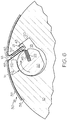
Fig. 6 is a schematic side view of a printing blanket mounted onto a blanket cylinder using a conventional single reel rod lock-up mechanism. -
Figs. 1 and2 illustrate aconventional blanket cylinder 10 having a conventional fabric-backedprinting blanket 12 to be mounted thereon using a single reelrod lockup mechanism 14.Blanket 12 includes at least a print surface layer and a reinforcing fabric backing ply. Conventional printing blankets may also include additional plies or layers (not shown) as is well known in the art. Lead and trail blanket bars 13 and 15 are secured to opposite ends of the blanket. As is conventional, a blanket bar is typically formed from metal and is used to reinforce the ends of a printing blanket and as an aid in inserting and securing the blanket ends in the lock-up mechanism. - The
gap 16 in the cylinder extends radially inwardly from the surface of the cylinder to form arecess 18 in which the cam-operated lockup mechanism is located.Gap 16 andrecess 18 extend substantially the entire width of the blanket cylinder. The single reel lockup includes arotatable cam 20 having a slot orrecess 22 therein.Recess 18 includes a shelf or cut-out 21 against which an edge of the leadend blanket bar 13 is mounted. The trailend blanket bar 15 is inserted intoslot 22, and, as best shown inFig. 2 , rotation ofcam 20 in the direction of the arrow causes the trail end of the blanket to tighten against the surface ofblanket cylinder 10. Further rotation results in tensioning of the blanket as it becomes locked around the outer circumference ofcylinder 10. - A problem with prior conventional fabric-backed blankets is that they tend to stretch when subjected to the rapid rotation of the blanket cylinder during printing operations. This stretching requires an operator to frequently shut down press operation so that the blanket can be re-tensioned and print quality maintained. The use of a non-extensible backing, such as a metal or other non-extensible backing, on a printing blanket addresses this problem, and the metal backing layer prevents stretching of the blanket after mounting on the blanket cylinder and during operation. The metal backing also provides dimensional stability to the blanket, resulting in high print quality, and eliminates the need for frequent re-tensioning of the blanket as would be required with conventional fabric-backed blankets.
-
Fig. 3 shows a cross-sectional view of one embodiment of theprinting blanket construction 30 of the present invention. Printingblanket 30 includes at least an outerprinting surface layer 32 which acts to transfer an inked image from a printing plate to a substrate and anon-extensible backing layer 38. As shown in this embodiment,blanket 30 may also optionally include one or morecompressible plies 34 and one or more reinforcing plies such as fabric plies 33 and 36. As shown, theplies non-extensible backing layer 38 with an adhesive 40. The adhesive used to adhere the plies to the non-extensible backing layer may comprise any of a number of conventional adhesives including hot melt adhesives, pressure sensitive adhesives, and curable polymers including rubber, urethane, epoxies, and the like. Alternatively, the plies may be formed directly onto the non-extensible backing layer. Preferably the blanket has an overall thickness of from about 0.070 to about 0.090 inches (about 1.75 to about 2.30 mm). - The
non-extensible backing layer 38 preferably comprises a flexible, but non-extensible material such as a thin metal or metal alloy sheet or other non-extensible material such as a polymeric material. A preferred material forbacking layer 38 is stainless steel having a thickness of from between about 0.006 to about 0.010 inches (about 0.15 to about 0.25 mm), which material is readily commercially available. Other materials may be used, so long as they are substantially non-extensible in use under normal operating conditions and so long as they have sufficient flexibility to be mounted onto conventional blanket cylinders. - Preferably, the
adhesive material 40 has a thickness of from approximately 0.001 to 0.008 inches (about 0.025 mm to about 0.2 mm) and may comprise any suitable adhesive including, but not limited to a pressure sensitive adhesive or a hot melt film which can be applied and then heated to an elevated temperature to activate its adhesive properties. Suitable adhesive are commercially available from a number of manufacturers. For example, one suitableadhesive material 40 may comprise a modified co-polymer of ethylene and vinyl acetate in the form of a hotmelt film. - Woven fabric ply 36 may be partially or entirely ground to adjust the thickness thereof. Fabric plies 33 and 36 have thicknesses, respectively, preferably in a range from about 0.008 to about 0.016 inches (from about 0.20 to about 0.4 mm) and most preferably, a thickness of about 0.011 inches (0.28 mm). Reinforcing plies 33 and 36 can comprise fabrics woven from cotton or synthetic yarns or fibers having both warp and weft fibers or yarns. One preferred fabric for use in the present invention is a square woven fabric in which the warp yarns are cotton (such as, for example, pima cotton) and the weft yarns are polyester (such as a spun polyester). The fabric is pre-stretched in a single direction along the length of the warp yarns such that the fabric as used in the manufacture of the image transfer blanket has little or no residual stretch in that direction.
- As taught in commonly-assigned
U.S. Pat. No. 6,530,321 to Andrew et al. , either or both of woven fabric plies 33 and 36 may be oriented in the blanket construction so that when the blanket is mounted ontoblanket cylinder 10, the weft fibers extend circumferentially about the cylinder. This orientation is 90° from the orientation of conventional fabric plies in a blanket (as that blanket would be mounted onto a cylinder) and provides additional flexibility for theblanket 12. - With respect to the
compressible layer 34, any known compressible or resilient material compatible with the other plies may be used in accordance with embodiments of the invention. A preferredcompressible layer 34, comprises a blend of nitrile and chloroprene-based rubber having a pore density to provide adequate strength and compressibility.Compressible layer 34 may comprise either open or closed-cell foam, with closed cell foams being preferred. Suitable compressible layer materials and their methods of fabrication include those materials disclosed in commonly-assignedU.S. Pat. No. 4,548,858 to Meadows . - Alternatively, the compressible layer may be formed by mixing a suitable salt such as hydrated magnesium sulfate with a polymeric material such as rubber and then curing and leaching the salt out, forming cavities in the rubber. Such a process is disclosed in commonly assigned
U.S. Pat. No. 3,928,521 to Haren et al. Still another method of forming the cushion layer includes the incorporation of microcapsules in an elastomeric matrix and fixing those microcapsules in a low temperature partial vulcanization step as described inU.S. Pat. No. 4,770,928 to Gaworoski . Preferably,compressible layer 34 will have a thickness in a range from about 0.022 to about 0.026 inches (from about 0.56 mm to about 0.67 mm) and most preferably, a thickness of about 0.245 inches (0.62 mm). - Elastomeric image
transfer surface layer 32 provides the image transfer face for theimage transfer blanket 30. The surface oflayer 32 may be ground to provide the final gauge thickness for the blanket. Suitable materials for use in the fabrication of imagetransfer surface layer 32 include a number of different polymers such as butyl rubber, EPDM rubber, nitrile rubber, natural rubber, neoprene rubber, a blend of nitrile and polyvinyl chloride, polyurethane, and synthetic rubber. - Those skilled in the art will appreciate that the preferred materials and their respective thickness may be varied or substituted. For example, additional adhesive, primer, anchor, and ply up layers may be provided in the blanket construction as needed and as is conventional in this art.
- One method for securing the plies to
non-extensible base layer 38 uses an adhesive film material. The adhesive may comprise a hot melt material, a pressure sensitive adhesive, or both. For example, it is possible to use an adhesive in which one side of a thin film support includes hot melt material while the other side includes a pressure sensitive adhesive. The method includes first removing any oils or other contaminants from the surface ofbase layer 38. Then, a primer is applied to prevent the reoccurrence of surface contamination and increase the ability of theadhesive film material 40 to bond. Theadhesive film material 40, which can be a hot melt film, a pressure sensitive adhesive, or a combination of both as described above, is interleaved between reinforcingply 36 andnon-extensible base layer 38. It should be understood, however, that it is possible to apply an initial layer of the adhesive to a side of the reinforcingply 36 to whichbase layer 38 is adhered so as to provide a "priming" adhesive film layer. Thereafter, the blanket plies andbase layer 38 are heated and then cooled to set theadhesive film material 40, thus adhesively securing the plies tobase layer 38 resulting in a preferred image transfer blanket construction. Other suitable methods of adhering the blanket layers together are known in this art and may also be used. -
Fig. 4 illustrates a sectional side view of one embodiment of the invention showing the location of the relief areas on the blanket. As shown,blanket 30 includes at least aprintable surface layer 32 and anon-extensible backing layer 38, preferably of a metal or metal alloy or other non-extensible material. Theblanket 30 has alead end 42 and atrail end 44 which are both adapted to be inserted into the gap of a printing blanket cylinder (as will be explained in greater detail below). Leadend 42 has ablanket bar 43 attached thereto, andtrail end 44 has ablanket bar 45 attached thereto. As shown,blanket bar 43 is secured around separatedportion 50 of the blanket carcass as well asnon-extensible layer 38.Blanket bar 45 is secured directly to opposing surfaces ofnon-extensible layer 38. - The
lead end 42 of the blanket includes afirst relief area 46 positioned inwardly from the lead end and extends substantially across the width of the blanket. Thefirst relief area 46 is defined by a gap in the surface print layer 32 (as well as in any other optional layers which are not shown) of the blanket, the gap overlies thenon-extensible backing layer 38 and is bounded on either side by blanket walls of the surface print layer. - The
non-extensible backing layer 38 has aportion 47 which extends beyond theblanket carcass 32 on thetrail end 44 of the blanket. Thetrail end 44 includes asecond relief area 48 which is positioned inwardly from the trail end and extends substantially across the width of the blanket. Thesecond relief area 48 is defined by a gap in the surface print layer (as well as in any additional optional layers which are not shown) of the blanket that overlies thenon-extensible backing layer 38.Second relief area 48 is bounded on either side by blanket walls of the surface print layer. - As is known in the art, the total length of the
blanket 30 will be dependent on the circumference of the blanket cylinder to which it is to be mounted. Typically such blankets will have overall lengths of from about 400 to about 1500 mm. Also, in general, the first and second relief areas will form gaps of from about 0.25 to about 10 mm, and preferably about 5 mm. The trail end of the non-extensible backing layer will extend from about 0 to about 25 mm, and preferably about 22 mm, beyond the end of the surface print layer. - First and
second relief areas non-extensible layer 38 extend beyondprinting surface layer 32 of the blanket.Portions portions portions - As shown in
Figs. 5 and6 , the first andsecond relief areas blanket 30 is mounted on the blanket cylinder, the relief areas substantially align with the point at which the lead and trail ends of the blanket are inserted into the gap in the blanket cylinder. Turning first toFig. 5 ,blanket 30 is to be mounted ontoblanket cylinder 10 using single reel rod lock-upmechanism 14.Blanket 30 includes at least asurface print layer 32 and anon-extensible backing layer 38 which is preferably a thin metal sheet or other non-extensible material.Blanket 30 also includeslead 42 andtrail 44 ends, withblanket bars - The
gap 16 inblanket cylinder 10 extends radially inwardly from the surface of the cylinder to form arecess 18 in which the cam operated lock-up mechanism is located.Gap 16 andrecess 18 extend substantially the entire width of the blanket cylinder. The single reel rod lock-up includes arotatable cam 20 having a slot orrecess 22 therein.Recess 18 includes a shelf or cut-out 21 against which an edge of thelead blanket bar 43 is mounted. The trailend blanket bar 45 is inserted intoslot 22. First 46 and second 48 relief areas on opposing lead and trail ends of the blanket permit the blanket ends to be easily bent and inserted intorecess 18. - As best shown in
Fig. 6 , rotation ofcam 20 in the direction of the arrow causes thetrail end 44 of the blanket to tighten against the outer circumference ofblanket cylinder 10. Further rotation results in securing the blanket ends in the lock-up mechanism such thatportions Fig. 6 ,relief areas gap 16 in the cylinder, leaving a narrow gap for printing purposes. As also shown inFig. 6 , therespective portions - Having described the invention in detail and by reference to specific embodiments thereof, it will be apparent that modifications and variations are possible without departing from the scope of the invention defined in the appended claims.
Claims (12)
- A printing blanket (30) comprising at least a printable surface layer (32) and a non-extensible backing layer (38), said printing blanket having opposing lead (42) and trail (44) ends adapted to be inserted into a gap (16) of a printing blanket cylinder (10); said lead end (42) of said blanket including a first relief area (46) positioned inwardly from said lead end and extending substantially across the width of said blanket, said first relief area defined by a gap in the blanket carcass (32) that overlies the non-extensible backing layer and is bounded on either side by blanket walls; and said trail end (44) of said blanket including a second relief area (48) positioned inwardly from said trail end and extending substantially across the width of said blanket, said second relief area defined by a gap in the at least one layer of said blanket overlying said non-extensible backing layer and bounded on either side by blanket walls, said first and second relief areas positioned such that when said blanket is mounted on said blanket cylinder, said relief areas substantially align with the point at which the lead and trail ends of said blanket are inserted into said gap in said blanket cylinder; characterized in that said non-extensible backing layer (38) extends beyond said blanket carcass (32) on said trail end (44) of said blanket.
- The printing blanket of claim 1 wherein the blanket carcass includes a compressible ply (34) positioned beneath said printable surface layer.
- The printing blanket of claim 2 wherein the blanket carcass includes at least one reinforcing ply (33).
- The printing blanket of claim 3 in which said reinforcing ply is selected from the group consisting of woven fabric, non-woven material, and polymers.
- The printing blanket of claim 1 including a blanket bar (43) on said lead end of said blanket.
- The printing blanket of claim 1 including a blanket bar (45) on said trail end of said blanket.
- The printing blanket of claim 1 wherein said non-extensible backing layer comprises metal or other non-extensible material.
- The printing blanket of claim 1 including blanket bars (43, 45) on each of said lead and trail ends of said blanket.
- In combination, a printing blanket (30) mounted on a blanket cylinder (10) which includes a gap (16) and a single reel rod lock-up mechanism (14) within said gap, said lock-up mechanism including a lead end shelf (21) and a rotatable rod (20) having a recess (22) therein opposite said shelf; said printing blanket being as defined in claim 8, wherein respective portions (50, 52) of said blanket carcass (32) which are positioned beyond said first and second relief areas meet in frictional engagement in said gap (16) of said printing blanket cylinder.
- The combination of claim 9 in which an edge of said blanket bar (43) on said lead end of said blanket engages said shelf (21).
- The combination of claim 9 in which said blanket bar (45) on said trail end of said blanket is inserted into the recess (22) in said rotatable rod (20), and said rod is rotated to lock the ends of said blanket into said lock-up mechanism (14).
- The combination of claim 11 in which rotation of said rod causes the surfaces of portions (50, 52) of the lead and trail ends of said blanket to come together in said gap (16) in said blanket cylinder in frictional engagement.
Applications Claiming Priority (2)
| Application Number | Priority Date | Filing Date | Title |
|---|---|---|---|
| US14/105,365 US9821547B2 (en) | 2013-12-13 | 2013-12-13 | Printing blanket with non-extensible backing mountable in a single reel rod lock-up |
| PCT/US2014/051800 WO2015088595A1 (en) | 2013-12-13 | 2014-08-20 | Printing blanket with non-extensible backing mountable in a single reel rod lock-up |
Publications (2)
| Publication Number | Publication Date |
|---|---|
| EP3079914A1 EP3079914A1 (en) | 2016-10-19 |
| EP3079914B1 true EP3079914B1 (en) | 2019-03-06 |
Family
ID=51453887
Family Applications (1)
| Application Number | Title | Priority Date | Filing Date |
|---|---|---|---|
| EP14758244.9A Active EP3079914B1 (en) | 2013-12-13 | 2014-08-20 | Printing blanket with non-extensible backing mountable in a single reel rod lock-up |
Country Status (4)
| Country | Link |
|---|---|
| US (1) | US9821547B2 (en) |
| EP (1) | EP3079914B1 (en) |
| JP (1) | JP6427193B2 (en) |
| WO (1) | WO2015088595A1 (en) |
Families Citing this family (5)
| Publication number | Priority date | Publication date | Assignee | Title |
|---|---|---|---|---|
| CN105216473B (en) * | 2015-08-28 | 2018-10-26 | 南京造币有限公司 | It is a kind of to be used for printing plate and preparation method thereof of the gravure to print technique |
| GB201609363D0 (en) * | 2016-05-26 | 2016-07-13 | Highcon Systems Ltd | System for impressing a relief pattern on a substrate |
| JP6357569B1 (en) * | 2017-06-23 | 2018-07-11 | 株式会社金陽社 | Blanket for printing |
| JP7100986B2 (en) * | 2018-01-26 | 2022-07-14 | 三菱重工機械システム株式会社 | Blanket and blanket body and printing press |
| US11628663B2 (en) | 2021-04-08 | 2023-04-18 | PMD Dies & Stereos Proprietary Limited | Flexographic printing imaging with lead and trail edge strips |
Family Cites Families (7)
| Publication number | Priority date | Publication date | Assignee | Title |
|---|---|---|---|---|
| US4635550A (en) | 1985-03-11 | 1987-01-13 | American Roller Company | Gap filler blanket for printing cylinder |
| US4829896A (en) | 1987-05-18 | 1989-05-16 | W. R. Grace & Co. | Apparatus for attaching a printing blanket to a printing cylinder |
| JPH09300588A (en) * | 1996-05-17 | 1997-11-25 | Mitsubishi Heavy Ind Ltd | Mounting of blanket on rotary press and mounting device |
| US5749298A (en) * | 1997-06-10 | 1998-05-12 | Reeves Brothers, Inc. | Arrangement for securing a printing blanket to a cylinder |
| CN1205054C (en) | 2000-03-21 | 2005-06-08 | 白昼国际有限公司 | Flexible image transfer-like leather cloth with non-extensible liner |
| DE102005017229A1 (en) * | 2005-04-14 | 2006-10-19 | Man Roland Druckmaschinen Ag | Ink transfer device of a printing press |
| US8783178B2 (en) * | 2005-11-09 | 2014-07-22 | Day International, Inc. | Printing blanket including a non-extensible backing layer and a relief area which may be mounted in a variety of lockup mechanisms |
-
2013
- 2013-12-13 US US14/105,365 patent/US9821547B2/en active Active
-
2014
- 2014-08-20 WO PCT/US2014/051800 patent/WO2015088595A1/en not_active Ceased
- 2014-08-20 JP JP2016538702A patent/JP6427193B2/en active Active
- 2014-08-20 EP EP14758244.9A patent/EP3079914B1/en active Active
Non-Patent Citations (1)
| Title |
|---|
| None * |
Also Published As
| Publication number | Publication date |
|---|---|
| US9821547B2 (en) | 2017-11-21 |
| WO2015088595A1 (en) | 2015-06-18 |
| US20140299010A1 (en) | 2014-10-09 |
| JP6427193B2 (en) | 2018-11-21 |
| EP3079914A1 (en) | 2016-10-19 |
| HK1226697A1 (en) | 2017-10-06 |
| JP2017502857A (en) | 2017-01-26 |
Similar Documents
| Publication | Publication Date | Title |
|---|---|---|
| US6530321B2 (en) | Flexible image transfer blanket having non-extensible backing | |
| US9649835B2 (en) | Printing blanket including a non-extensible backing layer and a relief area which may be mounted in a variety of lockup mechanisms | |
| US9821547B2 (en) | Printing blanket with non-extensible backing mountable in a single reel rod lock-up | |
| US4537129A (en) | Offset printing blanket | |
| CA2651816C (en) | Fixture for anti-marking coverings for printing presses | |
| US4452143A (en) | Offset printing blanket | |
| US7011021B2 (en) | Printing blanket sleeve with replaceable printing surface | |
| HK1226697B (en) | Printing blanket with non-extensible backing mountable in a single reel rod lock-up | |
| HK1165375B (en) | Printing blanket including a relief area and a combination thereof | |
| HK1124287B (en) | Printing blanket including a relief area, and combination of such a printing blanket | |
| HK1125338B (en) | Fixture for anti-marking coverings for printing presses |
Legal Events
| Date | Code | Title | Description |
|---|---|---|---|
| PUAI | Public reference made under article 153(3) epc to a published international application that has entered the european phase |
Free format text: ORIGINAL CODE: 0009012 |
|
| 17P | Request for examination filed |
Effective date: 20160705 |
|
| AK | Designated contracting states |
Kind code of ref document: A1 Designated state(s): AL AT BE BG CH CY CZ DE DK EE ES FI FR GB GR HR HU IE IS IT LI LT LU LV MC MK MT NL NO PL PT RO RS SE SI SK SM TR |
|
| AX | Request for extension of the european patent |
Extension state: BA ME |
|
| RIN1 | Information on inventor provided before grant (corrected) |
Inventor name: JAMES, BRIAN Inventor name: MESSER, JAMES Inventor name: SMATLAK, THOMAS |
|
| DAX | Request for extension of the european patent (deleted) | ||
| REG | Reference to a national code |
Ref country code: HK Ref legal event code: DE Ref document number: 1226697 Country of ref document: HK |
|
| GRAP | Despatch of communication of intention to grant a patent |
Free format text: ORIGINAL CODE: EPIDOSNIGR1 |
|
| STAA | Information on the status of an ep patent application or granted ep patent |
Free format text: STATUS: GRANT OF PATENT IS INTENDED |
|
| INTG | Intention to grant announced |
Effective date: 20180913 |
|
| GRAS | Grant fee paid |
Free format text: ORIGINAL CODE: EPIDOSNIGR3 |
|
| GRAA | (expected) grant |
Free format text: ORIGINAL CODE: 0009210 |
|
| STAA | Information on the status of an ep patent application or granted ep patent |
Free format text: STATUS: THE PATENT HAS BEEN GRANTED |
|
| AK | Designated contracting states |
Kind code of ref document: B1 Designated state(s): AL AT BE BG CH CY CZ DE DK EE ES FI FR GB GR HR HU IE IS IT LI LT LU LV MC MK MT NL NO PL PT RO RS SE SI SK SM TR |
|
| REG | Reference to a national code |
Ref country code: GB Ref legal event code: FG4D |
|
| REG | Reference to a national code |
Ref country code: AT Ref legal event code: REF Ref document number: 1104021 Country of ref document: AT Kind code of ref document: T Effective date: 20190315 Ref country code: CH Ref legal event code: EP |
|
| REG | Reference to a national code |
Ref country code: DE Ref legal event code: R096 Ref document number: 602014042365 Country of ref document: DE |
|
| REG | Reference to a national code |
Ref country code: IE Ref legal event code: FG4D |
|
| REG | Reference to a national code |
Ref country code: CH Ref legal event code: NV Representative=s name: TR-IP CONSULTING LLC, CH |
|
| REG | Reference to a national code |
Ref country code: NL Ref legal event code: FP |
|
| REG | Reference to a national code |
Ref country code: LT Ref legal event code: MG4D |
|
| PG25 | Lapsed in a contracting state [announced via postgrant information from national office to epo] |
Ref country code: LT Free format text: LAPSE BECAUSE OF FAILURE TO SUBMIT A TRANSLATION OF THE DESCRIPTION OR TO PAY THE FEE WITHIN THE PRESCRIBED TIME-LIMIT Effective date: 20190306 Ref country code: SE Free format text: LAPSE BECAUSE OF FAILURE TO SUBMIT A TRANSLATION OF THE DESCRIPTION OR TO PAY THE FEE WITHIN THE PRESCRIBED TIME-LIMIT Effective date: 20190306 Ref country code: FI Free format text: LAPSE BECAUSE OF FAILURE TO SUBMIT A TRANSLATION OF THE DESCRIPTION OR TO PAY THE FEE WITHIN THE PRESCRIBED TIME-LIMIT Effective date: 20190306 Ref country code: NO Free format text: LAPSE BECAUSE OF FAILURE TO SUBMIT A TRANSLATION OF THE DESCRIPTION OR TO PAY THE FEE WITHIN THE PRESCRIBED TIME-LIMIT Effective date: 20190606 |
|
| PG25 | Lapsed in a contracting state [announced via postgrant information from national office to epo] |
Ref country code: BG Free format text: LAPSE BECAUSE OF FAILURE TO SUBMIT A TRANSLATION OF THE DESCRIPTION OR TO PAY THE FEE WITHIN THE PRESCRIBED TIME-LIMIT Effective date: 20190606 Ref country code: GR Free format text: LAPSE BECAUSE OF FAILURE TO SUBMIT A TRANSLATION OF THE DESCRIPTION OR TO PAY THE FEE WITHIN THE PRESCRIBED TIME-LIMIT Effective date: 20190607 Ref country code: LV Free format text: LAPSE BECAUSE OF FAILURE TO SUBMIT A TRANSLATION OF THE DESCRIPTION OR TO PAY THE FEE WITHIN THE PRESCRIBED TIME-LIMIT Effective date: 20190306 Ref country code: HR Free format text: LAPSE BECAUSE OF FAILURE TO SUBMIT A TRANSLATION OF THE DESCRIPTION OR TO PAY THE FEE WITHIN THE PRESCRIBED TIME-LIMIT Effective date: 20190306 Ref country code: RS Free format text: LAPSE BECAUSE OF FAILURE TO SUBMIT A TRANSLATION OF THE DESCRIPTION OR TO PAY THE FEE WITHIN THE PRESCRIBED TIME-LIMIT Effective date: 20190306 |
|
| REG | Reference to a national code |
Ref country code: AT Ref legal event code: MK05 Ref document number: 1104021 Country of ref document: AT Kind code of ref document: T Effective date: 20190306 |
|
| PG25 | Lapsed in a contracting state [announced via postgrant information from national office to epo] |
Ref country code: AL Free format text: LAPSE BECAUSE OF FAILURE TO SUBMIT A TRANSLATION OF THE DESCRIPTION OR TO PAY THE FEE WITHIN THE PRESCRIBED TIME-LIMIT Effective date: 20190306 Ref country code: SK Free format text: LAPSE BECAUSE OF FAILURE TO SUBMIT A TRANSLATION OF THE DESCRIPTION OR TO PAY THE FEE WITHIN THE PRESCRIBED TIME-LIMIT Effective date: 20190306 Ref country code: PT Free format text: LAPSE BECAUSE OF FAILURE TO SUBMIT A TRANSLATION OF THE DESCRIPTION OR TO PAY THE FEE WITHIN THE PRESCRIBED TIME-LIMIT Effective date: 20190706 Ref country code: RO Free format text: LAPSE BECAUSE OF FAILURE TO SUBMIT A TRANSLATION OF THE DESCRIPTION OR TO PAY THE FEE WITHIN THE PRESCRIBED TIME-LIMIT Effective date: 20190306 Ref country code: CZ Free format text: LAPSE BECAUSE OF FAILURE TO SUBMIT A TRANSLATION OF THE DESCRIPTION OR TO PAY THE FEE WITHIN THE PRESCRIBED TIME-LIMIT Effective date: 20190306 Ref country code: ES Free format text: LAPSE BECAUSE OF FAILURE TO SUBMIT A TRANSLATION OF THE DESCRIPTION OR TO PAY THE FEE WITHIN THE PRESCRIBED TIME-LIMIT Effective date: 20190306 Ref country code: EE Free format text: LAPSE BECAUSE OF FAILURE TO SUBMIT A TRANSLATION OF THE DESCRIPTION OR TO PAY THE FEE WITHIN THE PRESCRIBED TIME-LIMIT Effective date: 20190306 |
|
| PG25 | Lapsed in a contracting state [announced via postgrant information from national office to epo] |
Ref country code: SM Free format text: LAPSE BECAUSE OF FAILURE TO SUBMIT A TRANSLATION OF THE DESCRIPTION OR TO PAY THE FEE WITHIN THE PRESCRIBED TIME-LIMIT Effective date: 20190306 Ref country code: PL Free format text: LAPSE BECAUSE OF FAILURE TO SUBMIT A TRANSLATION OF THE DESCRIPTION OR TO PAY THE FEE WITHIN THE PRESCRIBED TIME-LIMIT Effective date: 20190306 |
|
| REG | Reference to a national code |
Ref country code: DE Ref legal event code: R097 Ref document number: 602014042365 Country of ref document: DE |
|
| PG25 | Lapsed in a contracting state [announced via postgrant information from national office to epo] |
Ref country code: IS Free format text: LAPSE BECAUSE OF FAILURE TO SUBMIT A TRANSLATION OF THE DESCRIPTION OR TO PAY THE FEE WITHIN THE PRESCRIBED TIME-LIMIT Effective date: 20190706 Ref country code: AT Free format text: LAPSE BECAUSE OF FAILURE TO SUBMIT A TRANSLATION OF THE DESCRIPTION OR TO PAY THE FEE WITHIN THE PRESCRIBED TIME-LIMIT Effective date: 20190306 |
|
| PLBE | No opposition filed within time limit |
Free format text: ORIGINAL CODE: 0009261 |
|
| STAA | Information on the status of an ep patent application or granted ep patent |
Free format text: STATUS: NO OPPOSITION FILED WITHIN TIME LIMIT |
|
| PG25 | Lapsed in a contracting state [announced via postgrant information from national office to epo] |
Ref country code: DK Free format text: LAPSE BECAUSE OF FAILURE TO SUBMIT A TRANSLATION OF THE DESCRIPTION OR TO PAY THE FEE WITHIN THE PRESCRIBED TIME-LIMIT Effective date: 20190306 |
|
| 26N | No opposition filed |
Effective date: 20191209 |
|
| REG | Reference to a national code |
Ref country code: CH Ref legal event code: PCAR Free format text: NEW ADDRESS: ROUTE DU COUTSET 18, 1485 NUVILLY (CH) |
|
| PG25 | Lapsed in a contracting state [announced via postgrant information from national office to epo] |
Ref country code: SI Free format text: LAPSE BECAUSE OF FAILURE TO SUBMIT A TRANSLATION OF THE DESCRIPTION OR TO PAY THE FEE WITHIN THE PRESCRIBED TIME-LIMIT Effective date: 20190306 |
|
| PG25 | Lapsed in a contracting state [announced via postgrant information from national office to epo] |
Ref country code: TR Free format text: LAPSE BECAUSE OF FAILURE TO SUBMIT A TRANSLATION OF THE DESCRIPTION OR TO PAY THE FEE WITHIN THE PRESCRIBED TIME-LIMIT Effective date: 20190306 |
|
| PG25 | Lapsed in a contracting state [announced via postgrant information from national office to epo] |
Ref country code: LU Free format text: LAPSE BECAUSE OF NON-PAYMENT OF DUE FEES Effective date: 20190820 Ref country code: MC Free format text: LAPSE BECAUSE OF FAILURE TO SUBMIT A TRANSLATION OF THE DESCRIPTION OR TO PAY THE FEE WITHIN THE PRESCRIBED TIME-LIMIT Effective date: 20190306 |
|
| REG | Reference to a national code |
Ref country code: BE Ref legal event code: MM Effective date: 20190831 |
|
| PG25 | Lapsed in a contracting state [announced via postgrant information from national office to epo] |
Ref country code: IE Free format text: LAPSE BECAUSE OF NON-PAYMENT OF DUE FEES Effective date: 20190820 |
|
| PG25 | Lapsed in a contracting state [announced via postgrant information from national office to epo] |
Ref country code: BE Free format text: LAPSE BECAUSE OF NON-PAYMENT OF DUE FEES Effective date: 20190831 |
|
| PG25 | Lapsed in a contracting state [announced via postgrant information from national office to epo] |
Ref country code: CY Free format text: LAPSE BECAUSE OF FAILURE TO SUBMIT A TRANSLATION OF THE DESCRIPTION OR TO PAY THE FEE WITHIN THE PRESCRIBED TIME-LIMIT Effective date: 20190306 |
|
| PG25 | Lapsed in a contracting state [announced via postgrant information from national office to epo] |
Ref country code: MT Free format text: LAPSE BECAUSE OF FAILURE TO SUBMIT A TRANSLATION OF THE DESCRIPTION OR TO PAY THE FEE WITHIN THE PRESCRIBED TIME-LIMIT Effective date: 20190306 Ref country code: HU Free format text: LAPSE BECAUSE OF FAILURE TO SUBMIT A TRANSLATION OF THE DESCRIPTION OR TO PAY THE FEE WITHIN THE PRESCRIBED TIME-LIMIT; INVALID AB INITIO Effective date: 20140820 |
|
| PG25 | Lapsed in a contracting state [announced via postgrant information from national office to epo] |
Ref country code: MK Free format text: LAPSE BECAUSE OF FAILURE TO SUBMIT A TRANSLATION OF THE DESCRIPTION OR TO PAY THE FEE WITHIN THE PRESCRIBED TIME-LIMIT Effective date: 20190306 |
|
| PGFP | Annual fee paid to national office [announced via postgrant information from national office to epo] |
Ref country code: NL Payment date: 20230821 Year of fee payment: 10 |
|
| PGFP | Annual fee paid to national office [announced via postgrant information from national office to epo] |
Ref country code: GB Payment date: 20230822 Year of fee payment: 10 Ref country code: CH Payment date: 20230902 Year of fee payment: 10 |
|
| PGFP | Annual fee paid to national office [announced via postgrant information from national office to epo] |
Ref country code: FR Payment date: 20230825 Year of fee payment: 10 |
|
| REG | Reference to a national code |
Ref country code: CH Ref legal event code: PL |
|
| REG | Reference to a national code |
Ref country code: NL Ref legal event code: MM Effective date: 20240901 |
|
| GBPC | Gb: european patent ceased through non-payment of renewal fee |
Effective date: 20240820 |
|
| PG25 | Lapsed in a contracting state [announced via postgrant information from national office to epo] |
Ref country code: CH Free format text: LAPSE BECAUSE OF NON-PAYMENT OF DUE FEES Effective date: 20240831 |
|
| PG25 | Lapsed in a contracting state [announced via postgrant information from national office to epo] |
Ref country code: NL Free format text: LAPSE BECAUSE OF NON-PAYMENT OF DUE FEES Effective date: 20240901 |
|
| PG25 | Lapsed in a contracting state [announced via postgrant information from national office to epo] |
Ref country code: GB Free format text: LAPSE BECAUSE OF NON-PAYMENT OF DUE FEES Effective date: 20240820 |
|
| PG25 | Lapsed in a contracting state [announced via postgrant information from national office to epo] |
Ref country code: FR Free format text: LAPSE BECAUSE OF NON-PAYMENT OF DUE FEES Effective date: 20240831 |
|
| PGFP | Annual fee paid to national office [announced via postgrant information from national office to epo] |
Ref country code: DE Payment date: 20250820 Year of fee payment: 12 |
|
| PGFP | Annual fee paid to national office [announced via postgrant information from national office to epo] |
Ref country code: IT Payment date: 20250825 Year of fee payment: 12 |