EP3079369A1 - Data processing device and data processing method - Google Patents
Data processing device and data processing method Download PDFInfo
- Publication number
- EP3079369A1 EP3079369A1 EP14867046.6A EP14867046A EP3079369A1 EP 3079369 A1 EP3079369 A1 EP 3079369A1 EP 14867046 A EP14867046 A EP 14867046A EP 3079369 A1 EP3079369 A1 EP 3079369A1
- Authority
- EP
- European Patent Office
- Prior art keywords
- stream
- eliminated
- channel
- unit
- nps
- Prior art date
- Legal status (The legal status is an assumption and is not a legal conclusion. Google has not performed a legal analysis and makes no representation as to the accuracy of the status listed.)
- Granted
Links
Images






Classifications
-
- H—ELECTRICITY
- H04—ELECTRIC COMMUNICATION TECHNIQUE
- H04N—PICTORIAL COMMUNICATION, e.g. TELEVISION
- H04N21/00—Selective content distribution, e.g. interactive television or video on demand [VOD]
- H04N21/60—Network structure or processes for video distribution between server and client or between remote clients; Control signalling between clients, server and network components; Transmission of management data between server and client, e.g. sending from server to client commands for recording incoming content stream; Communication details between server and client
- H04N21/61—Network physical structure; Signal processing
- H04N21/6106—Network physical structure; Signal processing specially adapted to the downstream path of the transmission network
- H04N21/6143—Network physical structure; Signal processing specially adapted to the downstream path of the transmission network involving transmission via a satellite
-
- H—ELECTRICITY
- H04—ELECTRIC COMMUNICATION TECHNIQUE
- H04L—TRANSMISSION OF DIGITAL INFORMATION, e.g. TELEGRAPHIC COMMUNICATION
- H04L12/00—Data switching networks
- H04L12/64—Hybrid switching systems
- H04L12/6418—Hybrid transport
-
- H—ELECTRICITY
- H04—ELECTRIC COMMUNICATION TECHNIQUE
- H04L—TRANSMISSION OF DIGITAL INFORMATION, e.g. TELEGRAPHIC COMMUNICATION
- H04L65/00—Network arrangements, protocols or services for supporting real-time applications in data packet communication
- H04L65/60—Network streaming of media packets
- H04L65/61—Network streaming of media packets for supporting one-way streaming services, e.g. Internet radio
- H04L65/611—Network streaming of media packets for supporting one-way streaming services, e.g. Internet radio for multicast or broadcast
-
- H—ELECTRICITY
- H04—ELECTRIC COMMUNICATION TECHNIQUE
- H04N—PICTORIAL COMMUNICATION, e.g. TELEVISION
- H04N21/00—Selective content distribution, e.g. interactive television or video on demand [VOD]
- H04N21/20—Servers specifically adapted for the distribution of content, e.g. VOD servers; Operations thereof
- H04N21/23—Processing of content or additional data; Elementary server operations; Server middleware
- H04N21/236—Assembling of a multiplex stream, e.g. transport stream, by combining a video stream with other content or additional data, e.g. inserting a URL [Uniform Resource Locator] into a video stream, multiplexing software data into a video stream; Remultiplexing of multiplex streams; Insertion of stuffing bits into the multiplex stream, e.g. to obtain a constant bit-rate; Assembling of a packetised elementary stream
-
- H—ELECTRICITY
- H04—ELECTRIC COMMUNICATION TECHNIQUE
- H04N—PICTORIAL COMMUNICATION, e.g. TELEVISION
- H04N21/00—Selective content distribution, e.g. interactive television or video on demand [VOD]
- H04N21/20—Servers specifically adapted for the distribution of content, e.g. VOD servers; Operations thereof
- H04N21/23—Processing of content or additional data; Elementary server operations; Server middleware
- H04N21/236—Assembling of a multiplex stream, e.g. transport stream, by combining a video stream with other content or additional data, e.g. inserting a URL [Uniform Resource Locator] into a video stream, multiplexing software data into a video stream; Remultiplexing of multiplex streams; Insertion of stuffing bits into the multiplex stream, e.g. to obtain a constant bit-rate; Assembling of a packetised elementary stream
- H04N21/23608—Remultiplexing multiplex streams, e.g. involving modifying time stamps or remapping the packet identifiers
-
- H—ELECTRICITY
- H04—ELECTRIC COMMUNICATION TECHNIQUE
- H04N—PICTORIAL COMMUNICATION, e.g. TELEVISION
- H04N21/00—Selective content distribution, e.g. interactive television or video on demand [VOD]
- H04N21/20—Servers specifically adapted for the distribution of content, e.g. VOD servers; Operations thereof
- H04N21/23—Processing of content or additional data; Elementary server operations; Server middleware
- H04N21/236—Assembling of a multiplex stream, e.g. transport stream, by combining a video stream with other content or additional data, e.g. inserting a URL [Uniform Resource Locator] into a video stream, multiplexing software data into a video stream; Remultiplexing of multiplex streams; Insertion of stuffing bits into the multiplex stream, e.g. to obtain a constant bit-rate; Assembling of a packetised elementary stream
- H04N21/23611—Insertion of stuffing data into a multiplex stream, e.g. to obtain a constant bitrate
-
- H—ELECTRICITY
- H04—ELECTRIC COMMUNICATION TECHNIQUE
- H04N—PICTORIAL COMMUNICATION, e.g. TELEVISION
- H04N21/00—Selective content distribution, e.g. interactive television or video on demand [VOD]
- H04N21/20—Servers specifically adapted for the distribution of content, e.g. VOD servers; Operations thereof
- H04N21/23—Processing of content or additional data; Elementary server operations; Server middleware
- H04N21/236—Assembling of a multiplex stream, e.g. transport stream, by combining a video stream with other content or additional data, e.g. inserting a URL [Uniform Resource Locator] into a video stream, multiplexing software data into a video stream; Remultiplexing of multiplex streams; Insertion of stuffing bits into the multiplex stream, e.g. to obtain a constant bit-rate; Assembling of a packetised elementary stream
- H04N21/23614—Multiplexing of additional data and video streams
-
- H—ELECTRICITY
- H04—ELECTRIC COMMUNICATION TECHNIQUE
- H04N—PICTORIAL COMMUNICATION, e.g. TELEVISION
- H04N21/00—Selective content distribution, e.g. interactive television or video on demand [VOD]
- H04N21/20—Servers specifically adapted for the distribution of content, e.g. VOD servers; Operations thereof
- H04N21/23—Processing of content or additional data; Elementary server operations; Server middleware
- H04N21/238—Interfacing the downstream path of the transmission network, e.g. adapting the transmission rate of a video stream to network bandwidth; Processing of multiplex streams
- H04N21/2383—Channel coding or modulation of digital bit-stream, e.g. QPSK modulation
Definitions
- the present technology relates to a data processing device and a data processing method, and more particularly, to a data processing device and a data processing method, for example, capable of appropriately processing a stream.
- Non-Patent Document 1 As a broadcasting system of digital broadcasting, for example, there are a digital video broadcasting (DVB)-S2 employed in Europe and the like (Non-Patent Document 1).
- Non-Patent Document 1 DVB-S.2: ETSI EN 302 307 V1.2.1 (2009-08)
- CB channel bonding
- DVB-S2x (or DVB-S. 2 evo) is in the middle of formulation as a standard revising DVB-S2, in DVB-S2x, the employment of the CB technology has been reviewed.
- the present technology is devised in view of such situations and enables an appropriate process of a stream.
- a first data processing device of the present technology includes: an elimination unit that eliminates null packets (NP) included in a division stream of a predetermined channel acquired by dividing an input stream configured by a plurality of packets into division streams of a plurality of channels and generates a NP-eliminated stream including deleted null packets (DNP) representing the number of eliminated NPs; and a generation unit that generates a stream including the NP-eliminated stream and signaling as a size identifier representing a size of the DNP.
- NP null packets
- DNP deleted null packets
- a first data processing method of the present technology includes: eliminating null packets (NP) included in a division stream of a predetermined channel acquired by dividing an input stream configured by a plurality of packets into division streams of a plurality of channels and generating a NP-eliminated stream including deleted null packets (DNP) representing the number of eliminated NPs; and generating a stream including the NP-eliminated stream and signaling as a size identifier representing a size of the DNP.
- NP null packets
- null packets (NP) included in a division stream of a predetermined channel acquired by dividing an input stream configured by a plurality of packets into division streams of a plurality of channels are eliminated, and a NP-eliminated stream including deleted null packets (DNP) representing the number of eliminated NPs is generated.
- DNP deleted null packets
- a second data processing device of the present technology includes: aprocessingunit thatprocesses a streamtransmitted from a data processing device including an elimination unit that eliminates null packets (NP) included in a division stream of a predetermined channel acquired by dividing an input stream configured by a plurality of packets into division streams of a plurality of channels and generates a NP-eliminated stream including deleted null packets (DNP) representing the number of eliminated NPs and a generation unit that generates a stream including the NP-eliminated stream and signaling as a size identifier representing a size of the DNP.
- aprocessingunit thatprocesses a streamtransmitted from a data processing device including an elimination unit that eliminates null packets (NP) included in a division stream of a predetermined channel acquired by dividing an input stream configured by a plurality of packets into division streams of a plurality of channels and generates a NP-eliminated stream including deleted null packets (DNP) representing the number
- a second data processing method of the present technology includes: processing a stream transmitted from a data processing device including an elimination unit that eliminates null packets (NP) included in a division stream of a predetermined channel acquired by dividing an input stream configured by a plurality of packets into division streams of a plurality of channels and generates a NP-eliminated stream including deleted null packets (DNP) representing the number of eliminated NPs and a generation unit that generates a stream including the NP-eliminated stream and signaling as a size identifier representing a size of the DNP.
- NP null packets
- DNP deleted null packets
- a stream transmitted from a data processing device including: an elimination unit that eliminates null packets (NP) included in a division stream of a predetermined channel acquired by dividing an input stream configured by a plurality of packets into division streams of a plurality of channels and generates a NP-eliminated stream including deleted null packets (DNP) representing the number of eliminatedNPs; and a generation unit that generates a stream including the NP-eliminated stream and signaling as a size identifier representing a size of the DNP is processed.
- NP null packets
- DNP deleted null packets
- a third data processing device of the present technology includes: an elimination unit that eliminates null packets (NP) included in a division stream of a predetermined channel acquired by dividing an input stream configured by a plurality of packets into division streams of a plurality of channels and generates a NP-eliminated stream including deleted null packets (DNP) representing the number of eliminated NPs; and a generation unit that generates a stream including the NP-eliminated stream and a buffer capacity of a buffer storing the NP-eliminated stream and signaling as read start time from the buffer so as to generate a NP-inserted stream acquired by inserting NPs corresponding to a number represented by the DNP into the NP-eliminated stream.
- NP null packets
- a third data processing method of the present technology includes: eliminating null packets (NP) included in a division stream of a predetermined channel acquired by dividing an input stream configured by a plurality of packets into division streams of a plurality of channels and generating a NP-eliminated stream including deleted null packets (DNP) representing the number of eliminated NPs; and generating a stream including the NP-eliminated stream and a buffer capacity of a buffer storing the NP-eliminated stream and signaling as read start time from the buffer so as to generate aNP-inserted stream acquired by inserting NPs corresponding to a number represented by the DNP into the NP-eliminated stream.
- NP null packets
- null packets (NP) included in a division stream of a predetermined channel acquired by dividing an input stream configured by a plurality of packets into division streams of a plurality of channels are eliminated, and a NP-eliminated stream including deleted null packets (DNP) representing the number of eliminated NPs is generated.
- a stream including the NP-eliminated stream and a buffer capacity of a buffer storing the NP-eliminated stream and signaling as read start time from the buffer so as to generate a NP-inserted stream acquired by inserting NPs corresponding to a number represented by the DNP into the NP-eliminated stream is generated.
- a fourth data processing device of the present technology includes: aprocessingunit thatprocesses a streamtransmitted from a data processing device including an elimination unit that eliminates null packets (NP) included in a division stream of a predetermined channel acquired by dividing an input stream configured by a plurality of packets into division streams of a plurality of channels and generates a NP-eliminated stream including deleted null packets (DNP) representing the number of eliminated NPs and a generation unit that generates a stream including the NP-eliminated stream and a buffer capacity of a buffer storing the NP-eliminated stream and signaling as read start time from the buffer so as to generate a NP-inserted stream acquired by inserting NPs corresponding to a number represented by the DNP into the NP-eliminated stream.
- NP null packets
- DNP deleted null packets
- a fourth data processing method of the present technology includes: processing a stream transmitted from a data processing device including an elimination unit that eliminates null packets (NP) included in a division stream of a predetermined channel acquired by dividing an input stream configured by a plurality of packets into division streams of a plurality of channels and generates a NP-eliminated stream including deleted null packets (DNP) representing the number of eliminated NPs and a generation unit that generates a stream including the NP-eliminated stream and a buffer capacity of a buffer storing the NP-eliminated stream and signaling as read start time from the buffer so as to generate a NP-inserted stream acquired by inserting NPs corresponding to a number represented by the DNP into the NP-eliminated stream.
- NP null packets
- DNP deleted null packets
- a stream transmitted from a data processing device including: an elimination unit that eliminates null packets (NP) included in a division stream of a predetermined channel acquired by dividing an input stream configured by a plurality of packets into division streams of a plurality of channels and generates a NP-eliminated stream including deleted null packets (DNP) representing the number of eliminated NPs; and a generation unit that generates a stream including the NP-eliminated stream and a buffer capacity of a buffer storing the NP-eliminated stream and signaling as read start time from the buffer so as to generate a NP-inserted stream acquired by inserting NPs corresponding to a number represented by the DNP into the NP-eliminated stream is processed.
- NP null packets
- the data processing device may be an independent device or an internal block configuring one device.
- a stream can be appropriately processed.
- Fig. 1 is a block diagram that illustrates an example of the configuration of a transmission system (here, a system represents a logical aggregation of a plurality of devices regardless whether or not the devices of configurations are disposed inside a same casing) according to an embodiment of the present technology.
- the transmission system is configured by a transmission device 11 and a reception device 12.
- the transmission device 11 performs transmission (digital broadcasting) (data transmission) of a program of television broadcasting or the like.
- the transmission device 11 for example, divides a stream of target data that is a transmission target such as image data and audio data as a program into streams of a plurality of channels by using a CB technology and transmits (transfers) the divided streams through a transmission line 13 such as a satellite link, a terrestrial wave, or a cable (wire circuit).
- the reception device 12 receives streams of a plurality of channels transmitted from the transmission device 11 through the transmission line 13, restores the original stream, and outputs the restored original stream.
- Fig. 2 is a block diagram that illustrates an example of the configuration of the transmission device 11 illustrated in Fig. 1 .
- the transmission device 11 includes: a splitter 21; N buffers 22 1 to 22 N ; N channel processing units 23 1 to 23 N ; a symbol clock generating unit 26; and a time-related information generating unit 27.
- a transport stream (TS) having a high data rate of 100 Mega bit per second (Mbps) or the like, for example, configured by a plurality of TS packets #0, #1, ⁇ that is a stream of target data is supplied to the transmission device 11 as an input stream, and the transmission device 11 divides the input stream into division streams of N (or less) channels as a plurality of channels by using the CB technology and transmits the division streams.
- An input stream is supplied to the splitter 21, and the splitter 21 receives the input stream supplied thereto and divides the input stream into N (or less) division streams of channels ch#1 to ch#N.
- the splitter 21 repeats distributing the TS packet of the input stream to one channel among N channels ch#1 to ch#N and distributing a null packet (NP) to all the other channels for each TS packet of the input stream, thereby dividing the input stream into division streams of N channels ch#1 to ch#N.
- NP null packet
- the splitter 21 in response to a request (packet request) from a channel processing unit 23 n , supplies a division stream (packets thereof) of the channel ch#n (n-th channel) to the buffer 22 n .
- the buffer 22 n for example, is first in first out (FIFO) and sequentially stores division streams (packets thereof) of the channel ch#n supplied from the splitter 21 and sequentially supplies the stored division streams of the channel ch#n to the channel processing unit 23 n .
- FIFO first in first out
- the channel processing unit 23 n processes the division streams of the channel ch#n supplied from the buffer 22 n and transmits a channel stream s#1 of the channel ch#n acquired as a result thereof.
- the channel processing unit 23 n includes: a synchronization unit 31 n ; a null packet (NP) eliminating unit 32 n ; a forward error correction (FEC) unit 33 n ; and a MOD (Modulation) unit 34 n .
- division streams of the channel ch#n are supplied from the buffer 22 n , and an input stream time reference (ISCR) representing the transmission time of a packet that is one of input stream synchronizer's (ISSY), for example, defined in DVB-S2 and the like as time-related information relating to the transmission time of the packet and the like are supplied from the time-related information generating unit 27.
- ISCR input stream time reference
- ISSY input stream synchronizer's
- the synchronization unit 31 n adds the ISCR supplied from the time-related information generating unit 27 to the end of each packet of the division stream of the channel ch#n supplied from the buffer 22 n , when the packet is supplied to the synchronization unit 31 n , and supplies a stream acquired as a result thereof to the NP eliminating unit 32 n , as a stream of the channel ch#n after synchronization.
- the NP eliminating unit 32 n eliminates a NP from the stream of the channel ch#n after synchronization (a division stream in which an ISCR is added to each packet) supplied from the synchronization unit 31 n and supplies a stream acquired as a result thereof to the FEC unit 33 n as a NP-eliminated stream of the channel ch#n.
- the NP-eliminated stream of one channel can be transmitted using a transmission band that is narrower than that of a case where the input stream is transmitted.
- the FEC unit 33 n for example, adds a base band (BB) header to one or more packets of the NP-eliminated stream of the channel ch#n supplied from the NP eliminating unit 32 n , and adds in-band signaling defined in DVB-T2 and the like as is necessary, thereby functioning as a generation unit that generates a stream of a BB frame defined in DVB-S2 and the like.
- BB base band
- the FEC unit 33 n performs error correction coding such as BCH coding or LDPC coding of a BB frame and supplies a stream of a BB frame acquired as a result thereof to the MOD unit 34 n as a transmission post-FEC stream of the channel ch#n.
- error correction coding such as BCH coding or LDPC coding
- the MOD unit 34 n symbolizes the transmission post-FEC stream of the channel ch#n supplied from the FEC unit 33 n into a symbol for each predetermined number of bits and performs quadrature modulation of the symbol. Then, the MOD unit 34 n transmits a modulated signal acquired as a result of the quadrature modulation as a channel stream s#n of the channel ch#n.
- the symbol clock generating unit 26 generates a symbol clock that is a clock of the rate of the symbol and supplies the generated symbol clock to the time-related information generating unit 27.
- the time-related information generating unit 27 generates an ISSY such as an ISCR as time-related information in synchronization with a symbol clock supplied from the symbol clock generating unit 26 and supplies the generated ISSY to the channel processing units 23 1 to 23 N (the synchronization units 31 1 to 31 N thereof).
- an ISSY such as a same ISCR is supplied to all the channel processing units 23 1 to 23 N .
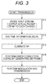
- Fig. 3 is a flowchart that illustrates the process (transmission process) of the transmission device 11 illustrated in Fig. 2 .
- step S11 the splitter 21 distributes each TS packet of an input stream supplied thereto to one channel among N channels ch#1 to ch#N and distributes a NP to all the other channels. Accordingly, the splitter 21 divides the input stream into division streams of N channels ch#1 to ch#N in which the TS packet of the input stream and a NP are present together and supplies the division stream of the channel ch#n to the buffer 22 n .
- the buffer 22 n sequentially stores the division stream of the channel ch#n supplied from the splitter 21 and sequentially supplies the storeddivision streamof the channel ch#n to the channel processing unit 23 n , and the process proceeds to steps S11 to step S12.
- step S12 in the channel processing unit 23 n the synchronization unit 31 n , adds an ISCR supplied form the time-related information generating unit 27 to the end of each packet of the division stream of the channel ch#n supplied from the buffer 22 n and supplies a stream acquired as a result thereof to the NP eliminating unit 32 n , as a stream of the channel ch#n after synchronization, and the process proceeds to step S13.
- step S13 the NP eliminating unit 32 n , eliminates a NP from the stream of the channel ch#n after synchronization (a division stream in which an ISCR is added to each packet) supplied from the synchronization unit 31 n , and supplies a stream acquired as a result thereof to the FEC unit 33 n as a NP-eliminated stream of the channel ch#n, and the process proceeds to step S14.
- step S14 the FEC unit 33 n adds a BB header to one or more packets of the NP-eliminated stream of the channel ch#n supplied from the NP eliminating unit 32 n , and adds in-band signaling as is necessary, thereby generating a stream of a BB frame.
- the FEC unit 33 n performs error correction coding of a BB frame and supplies a stream of a BB frame acquired as a result thereof to the MOD unit 34 n as a post FEC stream of the channel ch#n, and the process proceeds from step S14 to step S15.
- step S15 the MOD unit 34 n performs quadrature modulation of the transmission post-FEC stream of the channel ch#n supplied from the FEC unit 33 n and transmits a modulated signal acquired as a result of the quadrature modulation as a channel stream s#n of the channel ch#n, and the process ends.
- Steps S11 to S15 of the transmission process illustrated in Fig. 3 are performed in a pipeline manner.
- the transmission device 11 forms a NP-eliminated stream by dividing the input stream into division streams of a plurality of N channels ch#1 to ch#N in which the TS packet of the input stream and a NP are present together and eliminating a NP included in the division stream of each channel ch#n and then, transmits the NP-eliminated stream.
- the data rate of the NP-eliminated stream of each channel ch#n is decreased from the data rate of the input stream by an amount corresponding to the eliminated NP, and thus, the input stream of a high data rate can be transmitted by using a plurality of transmission lines each having a transmission band that is not relatively broad.
- the FEC unit 33 n performing the error correction coding of the NP-eliminated stream (a BB frame generated therefrom) of the channel ch#n, a circuit of which the processing speed is not relatively high can be employed.
- Fig. 4 is a block diagram that illustrates an example of the configuration of the reception device 12 illustrated in Fig. 1 .
- the reception device 12 includes: N channel processing units 51 1 to 51 N ; and a merging unit 52.
- the channel processing unit 51 n receives and processes a channel stream s#n of the channel ch#n transmitted from the transmission device 11.
- the channel processing unit 51 n includes: a de-modulation (DMD) unit 61 n ; an FEC unit 62 n ; a NP inserting unit 63 n , and a buffer 64 n .
- DMD de-modulation
- the DMD unit 61 n receives a channel stream s#n of a channel ch#n transmitted from the transmission device 11 and performs demodulation, which corresponds to the modulation performed by the MOD unit 34 n illustrated in Fig. 2 , of the channel stream s#n of the channel ch#n. Then, the DMD unit 61 n supplies a demodulated signal of the channel ch#n acquired as a result of the demodulation to the FEC unit 62 n .
- the FEC unit 62 n restores a NP-eliminated stream that is in the form of a BB frame acquired by the FEC unit 33 n illustrated in Fig. 2 by performing decoding of an error correction code as an error correction corresponding to the error correction coding performed by the FEC unit 33 n illustrated in Fig. 2 for the demodulated signal of the channel ch#n supplied from the DMD unit 61 n and supplies the restored NP-eliminated stream to the NP inserting unit 63 n as a reception post-FEC stream of the channel ch#n.
- the NP inserting unit 63 n supplies the reception post-FEC stream of the channel ch#n supplied from the FEC unit 62 n to the buffer 64 n so as to be stored therein.
- the NP inserting unit 63 n outputs a packet of the reception post-FEC stream stored in the buffer 64 n or a NP as is necessary, thereby appropriately inserting a NP into the reception post-FEC stream, in other words, the NP-eliminated stream (in the form of a BB frame).
- the NP inserting unit 63 n restores a stream of the channel ch#n after synchronization supplied from the synchronization unit 31 n , illustrated in Fig. 2 to the NP eliminating unit 32 and supplies the restored stream after synchronization to the merging unit 52 as a NP-inserted stream of the channel ch#n.
- the NP-inserted stream of the channel ch#n is a stream acquired by restoring the stream of the channel ch#n after synchronization supplied from the synchronization unit 31 n , to the NP eliminating unit 32, an ISCR is added to the end of the packet of the NP-inserted stream of the channel ch#n.
- the buffer 64 n under the control of the NP inserting unit 63 n , temporarily stores packets of the reception post-FEC stream of the channel ch#n supplied from the NP inserting unit 63 n , and reads the stored packets.
- the merging unit 52 based on the ISCRs added to the ends of packets of the NP-inserted streams of the channels ch#1 to ch#N supplied from the NP inserting units 63 1 to 63 N of the channel processing units 51 1 to 51 N , reconfigures an input stream configured by a plurality of TS packets ⁇ , #0, #1, ⁇ by aligning packets other than the NPs inserted by the NP inserting units 63 1 to 63 N among packets of the NP-inserted streams of the channels ch#1 to ch#N in order of the transmission time represented by the ISCRs and outputs the reconfigured input stream.
- Fig. 5 is a flowchart that illustrates an example of the process (reception process) of the reception device 12 illustrated in Fig. 4 .
- step S21 the DMD unit 61 n of the channel processing unit 51 n receives and demodulates a channel stream s#n of a channel ch#n transmitted from the transmission device 11 and supplies a demodulated signal of the channel ch#n acquired as a result of the demodulation to the FEC unit 62 n , and the process proceeds to step 22.
- step S22 the FEC unit 62 n restores a NP-eliminated stream that is in the form of a BB frame by performing an error correction of the demodulated signal of the channel ch#n supplied from the DMD unit 61 n and supplies the restored NP-eliminated stream to the NP inserting unit 63 n as a reception post-FEC stream of the channel ch#n, and the process proceeds to step S23.
- the NP inserting unit 63 n supplies the reception post-FEC stream of the channel ch#n supplied from the FEC unit 62 n to the buffer 64 n so as to be stored therein.
- the NP inserting unit 63 n restores a stream of the channel ch#n after synchronization that is in a form acquired by appropriately inserting a NP into the reception post-FEC stream (a NP-eliminated stream (in the form of a BB frame)) by outputting a packet of the reception post-FEC stream stored in the buffer 64 n or a NP and supplies the restored stream after synchronization to the merging unit 52 as a NP-inserted stream of the channel ch#n.
- step S23 the process proceeds from step S23 to step S24, and the merging unit 52, based on ISCRs added to the ends of packets of the NP-inserted streams of the channels ch#1 to ch#N supplied from the NP inserting units 63 1 to 63 N , reconfigures and outputs an input stream configured by a plurality of TS packets ⁇ , #0, #1, ⁇ and the process ends.
- steps S21 to S24 illustrated in Fig. 5 is performed in a pipeline manner.
- Fig. 6 is a diagram that illustrates an example of a stream handled by the transmission system illustrated in Fig. 1 .
- a of Fig. 6 illustrates an example of an input stream supplied to the splitter 21 of the transmission device 11 ( Fig. 2 ).
- the input stream is configured by a plurality of TS packets ⁇ , #0, #1, ⁇ .
- FIG. B of Fig. 6 illustrates an example of division streams supplied from the splitter 21 of the transmission device 11 ( Fig. 2 ) to the synchronization unit 31 n , through the buffer 22 n .
- the splitter 21 distributes each TS packet of the input stream illustrated in A of Fig. 6 to one of two channels ch#1 and ch#2 and distributes NPs to the other channel, thereby dividing the input stream into division streams of the two channels ch#1 and ch#2.
- the splitter 21 continuously distributes TS packets #0 to #4 of the input stream illustrated in A of Fig. 6 to the channel ch#1 and continuously distributes five NPs to the channel ch#2, thereafter, continuously distributes TS packets #5 to #9 of the input stream to the channel ch#2 and continuously distributes five NPs to the channel ch#1, and thereafter, similarly, distributes a TS packet of the input stream to one of the two channels ch#1 and ch#2 and distributes a NP to the other channel, whereby the input stream is divided into division streams of the two channels ch#1 and ch#2.
- FIG. 6 illustrates an example of a NP-eliminated stream supplied from the NP eliminating unit 32 n , of the transmission device 11 ( Fig. 2 ) to the FEC unit 33 n .
- the division stream of the channel ch#n acquired by the splitter 21 is regarded by the synchronization unit 31 n , as a stream of the channel ch#n after synchronization by adding an ISCR to the end of each packet of the division stream of the channel ch#n.
- the stream of the channel ch#n after synchronization is regarded as a NP-eliminated stream of the channel ch#n by eliminating NPs using the NP eliminating unit 32 n .
- the NP eliminating unit 32 n adds a deleted null packets (DNP), for example, of one byte representing the number of NPs eliminated from between the packet and the next packet.
- DNP deleted null packets
- C of Fig. 6 illustrates NP-eliminated streams of the channels ch#1 and ch#2 that are acquired from the division streams of the channels ch#1 and ch#2 illustrated in B of Fig. 6 .
- the NP-eliminated stream of each of the channels ch#1 and ch#2 is a stream acquired by adding an ISCR to the end of each packet of the division stream of each of the channels ch#1 and ch#2 illustrated in B of Fig. 6 , then eliminating each NP together with an ISCR added to the NP, and adding a DNP to the start of each packet (each packet remaining after the elimination of NPs).
- a DNP disposed at the start of the packet #0 is set to zero.
- a DNP disposed at the start of the packet #4 is set to five.
- D of Fig. 6 illustrates an example of a transmission post-FEC stream of the channel ch#2 acquired from the NP-eliminated stream of the channel ch#2 illustrated in C of Fig. 6 by the FEC unit 33 2 of the transmission device 11 ( Fig. 2 ).
- the transmission post-FEC stream of the channel ch#2 is a stream of a BB frame to which a BB header is added in a data field by using one or more packets (including an ISCR and a DNP added to each of the packets) of the NP-eliminated stream of the channel ch#2 illustrated in C of Fig. 6 as the data field (payload).
- packets #5 to #9 are arranged in a data field of a BB frame of one frame.
- in-band signaling (or padding) is added as is necessary, in Fig. 6 , the in-band signaling is not illustrated.
- E of Fig. 6 illustrates an example of the reception post-FEC stream of the channel ch#2 supplied from the FEC unit 62 2 of the reception device 12 ( Fig. 4 ) to the NP inserting unit 63 2 .
- the FEC unit 62 2 restores a NP-eliminated stream that is in the form of a BB frame acquired by the FEC unit 33 2 illustrated in Fig. 2 and supplies the restored NP-eliminated stream to the NP inserting unit 63 2 as a reception post-FEC stream of the channel ch#2.
- the reception post-FEC stream of the channel ch#2 is a stream similar to the NP-eliminated stream of the channel ch#2 that is in the form of a BB frame, in other words, the transmission post-FEC stream of the channel ch#2 illustrated in D of Fig. 6 .
- F of Fig. 6 illustrates an example of the NP-inserted stream of the channel ch#2 supplied from the NP inserting unit 63 2 of the reception device 12 ( Fig. 4 ) to the merging unit 52.
- the NP-inserted stream of the channel ch#2 illustrated in F of Fig. 6 is a stream acquired by insertingNPs corresponding to the number represented by the DNP included in the reception post-FEC stream of the channel ch#2 into packets (row) included in the BB frame of the reception post-FEC stream of the channel ch#2 illustrated in E of Fig. 6 .
- the NP-inserted stream of the channel ch#2 illustrated in F of Fig. 6 five NPs are inserted before the first packet #5 of the BB frame of the reception post-FEC stream of the channel ch#2 illustrated in E of Fig. 6 .
- the DNP representing the insertion of five NPs is added to the start of the last packet of a BB frame, which is not illustrated in the drawing, just prior to the BB frame of the reception post-FEC stream of the channel ch#2 illustrated in E of Fig. 6 .
- the DNP included in the reception post-FEC stream of the channel ch#2 illustrated in E of Fig. 6 is eliminated when the reception post-FEC stream of the channel ch#2 illustrated in E of Fig. 6 is formed as the NP-inserted stream of the channel ch#2 illustrated in F of Fig. 6 by the NP inserting unit 63 2 .
- the NP-inserted stream of the channel ch#2 illustrated in F of Fig. 6 is a stream acquired by restoring the stream of the channel ch#2 after synchronization supplied from the synchronization unit 31 n illustrated in Fig. 2 to the NP eliminating unit 32.
- an ISCR is added to the end of the packet of the NP-inserted stream of the channel ch#2 illustrated in F of Fig. 6
- the ISCR is not illustrated in F of Fig. 6 .
- an ISCR added to a NP inserted by the NP inserting unit 63 n is restored by being predicted through interpolation or the like based on ISCRs added to packets before and after the insertion of the NPs that is performed by the NP inserting unit 63 n .
- ISCRs added to the NPs can be configured to remain as they are without being eliminated.
- the NP inserting unit 63 n of the reception device 12 can accurately restore the stream of the channel ch#n after synchronization acquired by the synchronization unit 31 n illustrated in Fig. 2 , in other words, a stream in which an ISCR added by the synchronization unit 31 n illustrated in Fig. 2 is added to each packet of the division stream of the channel ch#n as a NP-inserted stream of the channel ch#n.
- Fig. 7 is a diagram that illustrates an example of a stream, which is handled by the transmission system illustrated in Fig. 1 , of a case where an ISCR added to a NP is configured to remain as it is without being eliminated in a case where the NP is eliminated from a stream of the channel ch#n after synchronization by the NP eliminating unit 32 n of the transmission device 11.
- a of Fig. 7 , B of Fig. 7 , and D of Fig. 7 to F of Fig. 7 are diagrams that are respectively similar to A of Fig. 6 , B of Fig. 6 , and D of Fig. 6 to F of Fig. 6 , description thereof will not be presented here.
- C of Fig. 7 illustrates NP-eliminated streams of the channels ch#1 and ch#2 acquired from the division streams of the channels ch#1 and ch#2 illustrated in B of Fig. 7 .
- the NP-eliminated stream of the channel ch#1 is a stream in which, after an ISCR is added to the end of each packet of the division stream of the channel ch#1 illustrated in B of Fig. 7 , each NP is eliminated in a form allowing the ISCR added to the NP to remain, and a DNP is added to the start of each packet.
- an ISCR added to each NP is present in a form not being added to the end of a packet.
- Fig. 8 is a diagram that illustrates the restoration of a stream of a channel ch#n after synchronization, which is performed by the NP inserting unit 63 n of the reception device 12 ( Fig. 4 ), as a NP-inserted stream of the channel ch#n.
- the NP inserting unit 63 n supplies a reception post-FEC stream of the channel ch#n supplied from the FEC unit 62 n to the buffer 64 n so as to be stored therein and outputs packets of the reception post-FEC stream stored in the buffer 64 n or NPs, thereby appropriately inserting the NPs into the reception post-FEC stream (a NP-eliminated stream (in the form of a BB frame)). In this way, the NP inserting unit 63 n restores the stream of the channel ch#n after synchronization as a NP-inserted stream of the channel ch#n.
- the NP inserting unit 63 n sets, among packets of the reception post-FEC stream of the channel ch#n supplied from the FEC unit 62 n , which have been written (stored) into the buffer 64 n , an oldest packet that has not been read from the buffer 64 n as a focus packet to be focused on.
- the NP inserting unit 63 n inserts NPs into the reception post-FEC stream of the channel ch#n supplied from the FEC unit 62 n by outputting the NPs corresponding to the number represented by a DNP added to the focus packet and thereafter outputting the focus packet, thereby restoring the stream of the channel ch#n after synchronization as a NP-inserted stream of the channel ch#n.
- each packet of the reception post-FEC stream of the channel ch#n written into the buffer 64 n needs to be stored in the buffer 64 n until the packet becomes the focus packet and then the output of NPs corresponding to the number represented by a DNP added to the focus packet ends.
- buffer input data data that is input (supplied) and written to the buffer 64 n
- buffer output data data that is read and output from the buffer 64 n
- Fig. 8 illustrates an example of changes in a total amount of the buffer input data and a total amount of the buffer output data with respect to time.
- the buffer input data is the reception post-FEC stream of the channel ch#n.
- the data rate of the buffer input data is constant.
- the total amount of the buffer input data increases at a constant inclination.
- the total amount of the buffer output data is changed, as illustrated by a dotted line in Fig. 8 , in accordance with NPs inserted into the reception post-FEC stream of the channel ch#n when the stream of the channel ch#n after synchronization is restored as a NP-inserted stream of the channel ch#n.
- the NP inserting unit 63 n outputs a packet of the reception post-FEC stream as the buffer input data stored in the buffer 64 n or a NP
- the packet of the reception post-FEC stream is read from the buffer 64 n , and accordingly, the total amount of the buffer output data increases.
- the NP inserting unit 63 n outputs a NP
- a packet of the reception post-FEC stream is not read from the buffer 64 n , and accordingly, the total amount of the buffer output data does not change (does not increase).
- the NP inserting unit 63 n continuously outputs the NPs, and a packet of the reception post-FEC stream is not read from the buffer 64 n , and accordingly, the total amount of the buffer output data does not change.
- a difference (hereinafter, referred to as a total amount difference) between the total amount of the buffer input data and the total amount of the buffer output data increases.
- a maximum total amount difference is a buffer amount that is required for the buffer 64 n .
- the total amount of the buffer output data does not change, and accordingly, the total amount difference increases.
- a NP insertion method for example, the ratio of NPs inserted into each channel, whether a NP is inserted into each channel in that order, or the like
- a buffer having a large buffer amount is required as the buffer 64 n of the reception device 12, and the cost of the reception device 12 increases in some cases.
- the buffer amount of the buffer 64 n of the reception device 12 is less than the total amount difference, there is a concern that the buffer 64 n is overflown, and the reception post-FEC stream of the channel ch#n supplied from the FEC unit 62 n cannot be appropriately processed (the streamof the channel ch#n after synchronization cannot be restored as a NP-inserted stream of the channel ch#n) by the NP inserting unit 63 n .
- the NP insertion method is defined such that an input stream is divided by the splitter 21 into division streams of the channels ch#1 to ch#N in which packets of the input stream are included at a predetermined constant density.
- NPs are inserted so as to be balanced, in other words, so as to be smoothed.
- the data rate of the NP-eliminated stream of the channel ch#n supplied to the FEC unit 33 n of the transmission device 11 is required to be a predetermined data rate of the processing speed (FEC rate) of the FEC unit 33 n or less.
- FEC rate processing speed
- the data rate of the NP-eliminated stream of the channel ch#n supplied to the FEC unit 33 n of the transmission device 11 is throughput of the data field of the BB frame (data acquired by excluding the BB header of the BB frame) generated by the FEC unit 33 n and is determined based on the rate of symbols, the modulation system of the quadrature modulation performed by the MOD unit 34 n , the error correction code employed by the FEC unit 33 n , on/off of a pilot signal in the modulated signal acquired by the MOD unit 34 n , and the like.
- the NP insertion method may be defined such that the ratio of NPs inserted to the channels ch#1 to ch#N is the same as the ratio of reciprocals of the data rates, which are determined in advance, of the NP-eliminated streams of the channels ch#1 to ch#N in the splitter 21.
- the number of NPs inserted to any other channel ch#n decreases.
- the data rate of the NP-eliminated stream of the channel ch#n is higher than the processing speed of the FEC unit 33 n of the channel ch#n, and it can be prevented that the FEC unit 33 n cannot appropriately process the NP-eliminated stream of the channel ch#n.
- the data rates of the NP-eliminated streams of the channels ch#1 to ch#N are predetermined data rates of the processing speeds of the FEC unit 33 n , which are determined in advance for the channels ch#1 to ch#N, or less. Accordingly, the FEC unit 33 n can appropriately process the NP-eliminated stream of the channel ch#n.
- Fig. 9 is a diagram that illustrates an example of a stream handled by the transmission system illustrated in Fig. 1 in a case where the NP insertion method as described above is employed.
- a of Fig. 9 illustrates an example of an input stream supplied to the splitter 21 of the transmission device 11 ( Fig. 2 ).
- the input stream illustrated in A of Fig. 9 is configured similarly to A of Fig. 6 .
- FIG. 9 illustrates an example of division streams supplied from the splitter 21 of the transmission device 11 ( Fig. 2 ) to the synchronization unit 31 n through the buffer 22 n .
- the splitter 21 distributes each TS packet of the input stream illustrated in A of Fig. 9 to one of two channels ch#1 and ch#2 and distributes NPs to the other channel in accordance with a NP insertion method, thereby dividing the input stream into division streams of the two channels ch#1 and ch#2 such that packets of the input stream are included at a predetermined constant density.
- the ratio of reciprocals of data rates, which are determined in advance, of NP-eliminated streams of the channels ch#1 and ch#2, for example, is set as 1 : 1.
- the input stream is divided by the splitter 21 into division streams of the channels ch#1 and ch#2 in which NPs are inserted such that the ratio of NPs inserted into the channels ch#1 and ch#2 is 1 : 1.
- the input stream is divided into division streams of the channels ch#1 and ch#2 by the splitter 21 by distributing a TS packet #0 of the input stream to the channel ch#1 and distributing one NP to the channel ch#2, thereafter, distributing a TS packet #2 of the input stream to the channel ch#2 and distributing one NP to the channel ch#1, and thereafter, alternately distributing TS packets of the input stream to the channels ch#1 and ch#2 and alternately distributing NPs to the channels ch#2 and ch#1.
- packets of the input stream are included at a constant density (in the example illustrated in B of Fig. 9 , the packets of the input stream are at a density of 0.5 packets per one packet of the division stream).
- FIG. 9 illustrates an example of a NP-eliminated stream supplied from the NP eliminating unit 32 n of the transmission device 11 ( Fig. 2 ) to the FEC unit 33 n .
- the division stream of the channel ch#n acquired by the splitter 21 is regarded by the synchronization unit 31 n as a stream of the channel ch#n after synchronization.
- the stream of the channel ch#n after synchronization is regarded as a NP-eliminated stream of the channel ch#n by eliminating NPs and inserting DNPs using the NP eliminating unit 32 n .
- C of Fig. 9 illustrates NP-eliminated streams of the channels ch#1 and ch#2 that are acquired from the division streams of the channels ch#1 and ch#2 illustrated in B of Fig. 9 .
- FIG. 9 illustrates an example of a transmission post-FEC stream of the channel ch#2 acquired from the NP-eliminated stream of the channel ch#2 illustrated in C of Fig. 9 by the FEC unit 33 2 of the transmission device 11 ( Fig. 2 ).
- the transmission post-FEC stream of the channel ch#2 is a stream of a BB frame in which a BB header is added to one or more packets of the NP-eliminated stream of the channel ch#2 illustrated in C of Fig. 9 .
- E of Fig. 9 illustrates an example of the reception post-FEC stream of the channel ch#2 supplied from the FEC unit 62 2 of the reception device 12 ( Fig. 4 ) to the NP inserting unit 63 2 .
- the FEC unit 62 2 restores a NP-eliminated stream that is in the form of a BB frame acquired by the FEC unit 33 2 illustrated in Fig. 2 and supplies the restored NP-eliminated stream to the NP inserting unit 63 2 as a reception post-FEC stream of the channel ch#2.
- the reception post-FEC stream of the channel ch#2 is a stream similar to the NP-eliminated stream of the channel ch#2 that is in the form of a BB frame, in other words, the transmission post-FEC stream of the channel ch#2 illustrated in D of Fig. 9 .
- FIG. 9 illustrates an example of the NP-inserted stream of the channel ch#2 supplied from the NP inserting unit 63 2 of the reception device 12 ( Fig. 4 ) to the merging unit 52.
- the NP-inserted stream of the channel ch#2 illustrated inFofFig. 9 is a stream acquired by inserting NPs corresponding to the number represented by the DNP included in the reception post-FEC stream of the channel ch#2 into packets (row) included in the BB frame of the reception post-FEC stream of the channel ch#2 illustrated in E of Fig. 9 and eliminating the DNP.
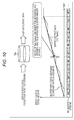
- Fig. 10 is a diagram that illustrates an example of changes of a total amount of the buffer input data and a total amount of the buffer output data with respect to time in a case where the NP insertion method described above is employed in the splitter 21.
- the data rate of the buffer input data that is the reception post-FEC stream of the channel ch#n is assumed to be constant.
- the total amount of the buffer input data increases at a constant inclination.
- the input stream is divided into division streams of channels ch#1 to ch#N in which packets of the input stream are included at a predetermined constant density.
- the NP inserting unit 63 n restores the stream of the channel ch#n after synchronization as a NP-inserted stream of the channel ch#n, it can be prevented that a total amount difference between the total amount of the buffer input data and the total amount of the buffer output data is large according to continuous output of NPs and reading of no packet from the buffer 64 n , and the buffer 64 n having a large buffer capacity is required.
- Fig. 10 illustrates the total amount of the buffer output data of a case where, as illustrated in B of Fig. 9 , the input stream is divided by the splitter 21 into division streams of channels ch#1 and ch#2 alternately including one of a NP and a packet of the input stream,.
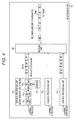
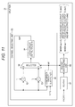
- Fig. 11 is a block diagram that illustrates a first configuration example of a splitter 21 dividing an input stream into division streams in accordance with the NP insertion method described above.
- FIG. 11 illustrates an example of the configuration of the splitter 21 of a case where an input stream is divided into division streams of two channels ch#1 and ch#2.
- the splitter 21 includes: a buffer 81; a packet distributing unit 82; and a channel selecting unit 83.
- Packets of the input stream are supplied to the buffer 81.
- the buffer 81 sequentially stores the packets of the input stream supplied thereto.
- a selection signal sel used for selecting a channel to which a packet is distributed is supplied to the packet distributing unit 82 from the channel selecting unit 83.
- the packet distributing unit 82 reads an oldest packet among packets stored in the buffer 81 as a focus packet to be focused on. In addition, the packet distributing unit 82 selects a channel to which the focus packet is distributed as a distribution channel in accordance with a selection signal sel supplied from the channel selecting unit 83 and distributes (outputs) the focus packet to the distribution channel.
- the packet distributing unit 82 selects one of two channels ch#1 and ch#2 as a distribution channel and distributes the focus packet to the distribution channel.
- the packet distributing unit 82 distributes (outputs) NPs to the channel selected as the distribution channel.
- the channel selecting unit 83 includes: a latch circuit 91; computing units 92 and 93; a selector 94; and a comparison circuit 95.
- the data rates of the channels ch#1 and ch#2 will be denoted as r 1 and r 2 .
- the latch circuit 91 latches a value "sum", which is supplied from the selector 94, having an initial value of "0" at timing synchronized with the packet of the input stream and supplies the latched value to the computing units 92 and 93 and the comparison circuit 95.
- the addition values are supplied from the computing units 92 and 93, and the selection signal sel is supplied from the comparison circuit 95.
- the selection signal sel takes a value of "0" or "1".
- the selection signal sel having a value of "0” represents that the channel ch#2 is selected as the distribution channel
- the selection signal sel having a value of "1" represents that the channel ch#1 is selected as the distribution channel.
- the selector 94 selects the addition value supplied from the computing unit 92 or the addition value supplied from the computing unit 93 in accordance with the selection signal sel supplied from the comparison circuit 95 and supplies the selected addition value to the latch circuit 91.
- the comparison circuit 95 compares the value "sum” supplied from the latch circuit 91 with an addition value "r 1 + r 2 " of the data rates of the channels ch#1 and ch#2. Then, the comparison circuit 95 outputs the selection signal sel having the value of "1” in a case where the value "sum” is the addition value "r 1 + r 2 " or more and outputs the selection signal sel having the value of "0” in a case where the value "sum” is less than the addition value "r 1 + r 2 ".
- the selection signal sel output by the comparison circuit 95 is supplied to the packet distributing unit 82 and the selector 94.
- the selection signal sel used for selecting the channel (distribution channel) to which the focus packet is distributed is generated by the channel selecting unit 83 based on the data rates r 1 and r 2 of the channels ch#1 and ch#2 such that the ratio of NPs inserted into the channels ch#1 and ch#2 is the same as the ratio of the reciprocals of the data rates r 1 and r 2 of the channels ch#1 and ch#2 and is supplied to the packet distributing unit 82.
- the selection signal sel is generated by the channel selecting unit 83 such that the channel ch#1 is selected as the distribution channel every (r 1 + r 2 )/r 1 packets, and the channel ch#2 is selected as the distribution channel every (r 1 + r 2 )/r 2 packets.
- the packet distributing unit 82 selects one of the channels ch#1 and ch#2 as the distribution channel in accordance with the selection signal sel supplied from the channel selecting unit 83 and distributes (outputs) the focus packet stored in the buffer 81 to the distribution channel and distributes (outputs) a NP to the other channel.
- Fig. 12 is a diagram illustrating the operation of the splitter 21 illustrated in Fig. 11 that is performed in a case where the data rates r 1 and r 2 are respectively "1" and "2".
- the selection signal sel becomes "0", and the channel ch#2 is selected as the distribution channel.
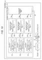
- Fig. 13 is a block diagram that illustrates a second configuration example of the splitter 21 dividing an input stream into division streams in accordance with the NP insertion method described above.
- Fig. 13 illustrates an example of the configuration of the splitter 21 of a case where an input stream is divided into division streams of three channels ch#1 to ch#3.
- the splitter 21 illustrated in Fig. 13 includes a buffer 81 and a packet distributing unit 82, which is common to the case illustrated in Fig. 11 .
- the splitter 21 illustrated in Fig. 13 includes a channel selecting unit 111 instead of the channel selecting unit 83, which is different from that case illustrated in Fig. 11 .
- the channel selecting unit 111 similarly to the channel selecting unit 83 illustrated in Fig. 11 , generates a selection signal sel used for selecting a channel to which a focus packet is distributed based on the data rates of the channels ch#1 to ch#3 and supplies the generated selection signal to the packet distributing unit 82.
- the selection flag flagr takes a value of "0" or "1".
- the selection flag flag n having the value of "1" represents that the channel ch#n is selected (can be selected) as the distribution channel, and the selection flag flagr, having the value of "0" represents that the channel ch#n is not selected as the distribution channel.
- the packet distributing unit 82 illustrated in Fig. 13 to which the selection flag flag n as described above is supplied as the selection signal sel in a case where the selection flag flag n supplied as the selection signal sel is "1", selects a channel ch#n among the channels ch#1 to ch#3 as the distribution channel and distributes the focus packet to the channel ch#n that is the distribution channel.
- the packet distributing unit 82 distributes NPs to all the channels that have not been selected as the distribution channel among the channels ch#1 to ch#3.
- the channel selecting unit 83 includes: counters 121 1 to 121 3 and selection flag output units 122 1 to 122 3 , which are respectively used for the channels ch#1 to ch#3 and a selection control unit 123.
- the data rates of the channels ch#1, ch#2, and ch#3 will be denoted as r 1 , r 2 , and r 3 .
- the counter 121 1 counts a count value sum 1 at timing synchronized with the packet of the input stream and supplies the count value sum 1 to the selection flag output unit 122 1 .
- the counter 121 2 counts a count value sum 2 at timing synchronized with the packet of the input stream and supplies the count value sum 2 to the selection flag output unit 122 2 .
- the counter 121 3 counts a count value sum 3 at timing synchronized with the packet of the input stream and supplies the count value sum 3 to the selection flag output unit 122 3 .
- the selection flag output unit 122 n outputs the selection flag flagr, having the value of "0" to the selection control unit 123 as a default value.
- the selection flag output unit 122 n outputs the selection flag flag n having the value of "1" to the selection control unit 123.
- the selection control unit 123 selects one of selection flags flagr, of which the value is "1" among the selection flags flag 1 to flag 3 supplied from the selection flag output units 122 1 to 122 3 as the selection signal sel and supplies the selected selection flag to the packet distributing unit 82.
- the selection control unit 123 performs control of the selection flag output unit 122 n such that the value of the selection flag flagr, selected as the selection signal sel is reset to "0".
- the selection control unit 123 for example, is assumed to select the selection flags flag 1 , flag 2 , and flag 3 as the selection signal sel in the described order with priority, in a case where the selection flag flag 1 is "1", the selection flag flag 1 is selected as the selection signal sel.
- the selection flag flag 2 is selected as the selection signal sel.
- the selection flag flag 3 is selected as the selection signal sel.
- the selection signal sel used for selecting the distribution channel is generated by the channel selecting unit 111 based on the data rates r 1 to r 3 of the channels ch#1 to ch#3 such that the ratio of NPs inserted into the channels ch#1 to ch#3 is the same as the ratio of the reciprocals of the data rates r 1 to r 3 of the channels ch#1 to ch#3 and is supplied to the packet distributing unit 82.
- the selection signal sel is generated by the channel selecting unit 111 such that the channel ch#1 is selected as the distribution channel every (r 1 + r 2 + r 3 ) /r 1 packets, the channel ch#2 is selected as the distribution channel every (r 1 + r 2 + r 3 )/r 2 packets, and the channel ch#3 is selected as the distribution channel every (r 1 + r 2 + r 3 ) /r 3 packets.
- the packet distributing unit 82 selects one channel ch#n of the channels ch#1 to ch#3 as the distribution channel in accordance with the selection signal sel supplied from the channel selecting unit 111 and distributes (outputs) the focus packet stored in the buffer 81 to the distribution channel and distributes (outputs) NPs to the other two channels.
- the configuration illustrated in Fig. 13 can be also applied to a splitter 21 of a case where the input stream is divided into division streams of two channels or a case where the input stream is divided into division streams of four or more channels.
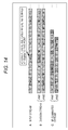
- Fig. 14 is a diagram that illustrates an example of the process of the transmission device 11 for an input stream including NPs.
- Fig. 14 illustrates an example of an input stream, division streams, and NP-eliminated streams.
- a of Fig. 14 illustrates an example of the input stream including NPs.
- NP included in the input stream.
- FIG. 14 illustrates an example of division streams of two channels ch#1 and ch#2 generated by the splitter 21 for the input stream illustrated in A of Fig. 14 .
- NPs inserted by the splitter 21 and NP's included in the input stream are present together.
- FIG. 14 illustrates an example of NP-eliminated streams of the channels ch#1 and ch#2 acquired by the NP eliminating unit 32 n for the division streams of the channels ch#1 and ch#2 illustrated in B of Fig. 14 .
- the NP eliminating unit 32 n as described above, generates the NP-eliminated streams by eliminating NPs included in the division streams (streams after synchronization generated by the synchronization unit 31 n therefrom).
- NPs and NP's are present together in the division stream, when NP's are configured to be eliminated in addition to NPs by the NP eliminating unit 32 n , it is necessary to insert NP's in addition to the NPs in a case where a NP-inserted stream is generated by the NP inserting unit 63 n of the reception device 12.
- NPs inserted in a case where division streams are generated by the splitter 21 are eliminated by the NP eliminating unit 32 n , and NP's that are originally included in the input stream may be caused to remain without being eliminated.
- NP-eliminated streams illustrated in C of Fig. 14 only NPs, which have been inserted by the splitter 21, included in the division streams illustrated in B of Fig. 14 are eliminated, and NP' s that are included in the input stream from the beginning are not eliminated but remain as they are.
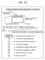
- Fig. 15 is a diagram that illustrates an example of a method for discriminating NPs inserted by the splitter 21 and NP's originally included in an input stream from each other.
- the NP eliminating unit 32 n of the transmission device 11 In order for the NP eliminating unit 32 n of the transmission device 11 to eliminate only NPs inserted by the splitter 21 from the division streams (streams after synchronization acquired therefrom) and to cause NP' s included in the input stream from the beginning not to be eliminated but to remain as they are, it is necessary to discriminate NPs inserted by the splitter 21 and NP' s included in the input stream form the beginning from each other.
- Fig. 15 illustrates the format of the TS packet.
- a program PID is included, and it can be recognized whether the TS packet is a NP (NP') based on the program PID.
- NULL identification information for example, it can be employed to set the most significant bit of a fixed synchronization word 0x47 (here, 0x represents that a value following it is a hexadecimal number) included in the TS header to "1" and to set the synchronization word to 0xC7.
- the NULL identification information may be employed to set a part or the whole of the payload of the TS packet (that is a NP or a NP') to a specific value representing a NP or a NP'.
- a specific value for example, a bit string in which only the most significant bit is "1", and the other bits are "0"s may be employed.
- NULL identification information a configuration in which NULL identification information representing a NP is included only in the NP, a configuration in which NULL identification information representing a NP' is included only in the NP', or a configuration in which NULL identification information representingaNP is included in the NP, and NULL identification information representing a NP' is included in the NP' may be employed.
- the NULL identification information representing a NP' is included in the NP', for a process performed after the process of the NP eliminating unit 32 n , it is necessary to return the NP' to a state before the inclusion of the NULL identification information.
- the NULL identification information it is preferable to include the NULL identification information representing a NP only in the NP.
- a NP including the NULL identification information representing a NP is eliminated by the NP eliminating unit 32 n , there is no influence on a process performed after the process of the NP eliminating unit 32 n (it is not necessary to return a NP including the NULL identification information representing a NP to a state before the inclusion of the NULL identification information).
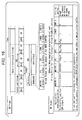
- Fig. 16 is a diagram that illustrates a size identifier representing the size of a DNP.
- the NP eliminating unit 32 n eliminates NPs from a stream after synchronization and sets the stream after synchronization as a NP-eliminated stream, to the start of each packet of the NP-eliminated stream, a DNP of one byte representing the number of NPs eliminated from between the packet and the next packet is added.
- the splitter21 in a case where the number N of channels for dividing an input stream into division streams is large, the number of continuous NPs in the division stream tends to be large.
- the NP eliminating unit 32 n can eliminate only 255 NPs that are continuous.
- the size of the DNP for example, two bytes larger than one byte may be employed.
- the NP eliminating unit 32 n can eliminate continuous NPs corresponding to a large number of 65535.
- the DNP is added to the start of each packet of the NP-eliminated stream, in a case where the size of the DNP is two bytes, the overhead of the NP-eliminated stream is twice of that of a case where the size of the DNP is one byte.
- the number of continuous NPs in the division stream tends to be small.
- the NP eliminating unit 32 n NPs corresponding to a number exceeding a number that can be represented by the DNP of one byte are not eliminated).
- the FEC unit 33 n can generate a stream including signaling as a size identifier representing the size of the DNP and a NP-eliminated stream.
- the FEC unit 33 n as described above, generates a stream of a BB frame by adding a BB header and necessary in-band signaling to one or more packets of the NP-eliminated stream of the channel ch#n supplied from the NP eliminating unit 32 n .
- the size identifier may be included in the BB header of a BB frame.
- Fig. 16 illustrates the format of the BB frame.
- a field in which a fixed value is set may be employed.
- the BB header as examples of a field in which a fixed value is set, there are UPL of two bytes and SYNC of one byte.
- UPL of two bytes
- SYNC of one byte.
- One or more bits of UPL or SYNC having such fixed values may be employed as the size identifier.
- one bit of UPL or SYNC having a fixed value is employed as the size identifier.
- the size identifier may be configured such that, in a case where the size of the DNP is one byte, one bit of UPL or SYNC having a fixed value as the size identifier is caused to have the original value, and, in a case where the size of the DNP is one byte, one bit of UPL or SYNC having a fixed value as the size identifier has a value acquired by inverting the original value.
- the size of the DNP not only one byte or two bytes, a size of three bytes or more may be employed.
- the NP inserting unit 63 n of the reception device 12 recognizes the size of the DNP included in the reception post-FEC stream, in other words, the NP-eliminated stream that is in the form of a BB frame based on the size identifier and inserts NPs corresponding to the number represented by the DNP of the size.
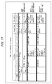
- Fig. 17 is a diagram that illustrates the format of an ISSY.
- the ISCR as described above, is time information representing the transmission time of a packet and is information of two or three bytes.
- the BUFS is information of (substantially) two bytes representing a buffer capacity (required buffer amount) that is required for the buffer 64 n in which a reception post-FEC stream is stored when the NP inserting unit 63 n restores the stream after synchronization as a NP-inserted stream by inserting NPs to the reception post-FEC stream.
- BUFS_UNIT two bits that are the fifth and sixth bits from the start of the bit string as the BUFS of two bytes (First Byte and Second Byte) are called BUFS_UNIT and represent the unit of the buffer capacity represented by the BUFS.
- 10 bits from the seventh bit to the last 16th bit represent the value of the buffer capacity.
- the NP inserting unit 63 n secures a storage area as the buffer 64 n of a buffer capacity represented by the BUFS and restores the stream after synchronization into a NP-inserted stream while writing the reception post-FEC stream into the buffer 64 n .
- the BUFSTAT is information of (substantial) two bytes representing read start time at which the NP inserting unit 63 n reads a packet from the buffer 64 n at the time of restoring the stream after synchronization as a NP-inserted stream by reading the packet stored in the buffer 64 n (the reception post-FEC stream).
- BUFSTAT_UNIT two bits that are fifth and sixth bits from the start of the bit string as the BUFSTAT of two bytes (First Byte and Second Byte) are called BUFSTAT_UNIT and represent the unit of the read start time represented by the BUFSTAT.
- 10 bits from the seventh to the last 16th bits represent the value of the read start time.
- the 10 bits of the BUFSTAT represent the read start time using a data remaining amount of the buffer 64 n at the time of reading a packet from the buffer 64 n .
- the reception device 12 for example, when a stream after synchronization is restored as a NP-inserted stream by the NP inserting unit 63 n reading of a packet from the buffer 64 n is started at timing (time) represented by the BUFSTAT.
- the ISCR is added by the synchronization unit 31 n of the transmission device 11 to each packet of the division stream so as to reconfigure an input stream by using the merging unit 52 of the reception device 12.
- the ISCR is added to each packet, but the BUFS and the BUFSTAT cannot be added to the packet.
- the transmission device 11 needs to transmit signaling as the BUFS and the BUFSTAT using a method different from that of the ISCR.
- the BUFS and the BUFSTAT may be included in the BB header of the BB frame of which the stream is generated by the FEC unit 33 n .
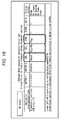
- Fig. 18 is a diagram that illustrates the format of the BB header.
- the BUFS and the BUFSTAT similarly to the size identifier, for example, UPL or SYNC that is a field of the BB header in which a fixed value is set may be employed.
- the BUFS and the BUFSTAT may be included in the UPL, and the size identifier may be included in the SYNC.
- the size identifier of one bit may be included in the SYNC of one byte of the BB header of each BB frame.
- All the BUFS and the BUFSTAT are two bytes and thus, may be included in the UPL of two bytes of the BB header of each BB frame, for example, in a periodical (regular) manner such as an alternating manner.
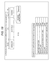
- Fig. 19 is a diagram that illustrates another method for transmitting the size identifier, the BUFS, and the BUFSTAT.
- Fig. 19 is a diagram that illustrates the format of the BB frame.
- in-band signaling may be added to the BB frame.
- new in-band signaling (hereinafter, referred to as new in-band signaling) may be employed instead of such in-band signaling.
- the new in-band signaling includes: a size identifier of one bit, BUFSTAT_UNIT of two bits, BUFSTAT (a value of the transmission start time as the BUFSTAT) of 10 bits, BUFS_UNIT of two bits, and BUFS (a value of the buffer capacity as the BUFS) of 10 bits.
- the new in-band signaling is added to the BB frame.
- a stream configured by a plurality of packets other than the TS may be employed as the input stream.
- a series of the processes described above can be performed either by hardware or by software.
- a program configuring the software is installed to a general-purpose computer or the like.
- Fig. 20 is a diagram that illustrates an example of the configuration of a computer according to an embodiment to which the program executing the series of processes described above is installed.
- the program may be recorded in a hard disk 205 or a ROM 203 as a recording medium built in the computer in advance.
- the program may be stored (recorded) on a removable recording medium 111.
- a removable recording medium 111 maybe provided as so-called package software.
- the removable recording medium 111 there are a flexible disk, a compact disc read only memory (CD-ROM), a magneto optical (MO) disk, a digital versatile disc (DVD), a magnetic disk, a semiconductor memory, and the like.
- the program may be downloaded to a computer through a communication network or a broadcasting network and be installed to a built-in hard disk 205.
- the program for example, may be transmitted from a download site to the computer in a wireless manner through satellites for digital satellite broadcasting or may be transmitted to the computer in a wired manner through a network such as a local area network (LAN) or the Internet.
- LAN local area network
- the computer includes a central processing unit (CPU) 202 therein, and an input/output interface 110 is connected to the CPU 202 through a bus 201
- the CPU 202 executes a program that is stored in the read only memory (ROM) 203 in accordance with the instruction.
- the CPU 202 loads a program stored in the hard disk 205 into a random access memory (RAM) 204 and executes the program.
- the CPU 202 performs a process according to the above-described flowchart or a process performed based on the above-described configuration of the block diagrams. Then, as is necessary, the CPU 202 outputs the processing result, for example, from an output unit 206 through the input/output interface 110, transmits the processing result from the communication unit 208, and records the processing result in a hard disk 205.
- the input unit 207 is configured by a keyboard, a mouse, amicrophone, or the like
- the output unit 206 is configured by a liquid crystal display (LCD), a speaker, or the like.
- LCD liquid crystal display
- the process executed by the computer in accordance with the program does not need to be performed necessarily in a time series in accordance with the sequence described in the flowchart.
- the process executed by the computer in accordance with the program includes a process (for example, a parallel process or a process using an object) that is performed in a parallel manner or in an individual manner.
- the program may be processed by one computer or may be processed by a plurality of computers in a distributed manner.
- the program may be transmitted to a remote computer and be executed.
- a system represents an aggregation of a plurality of constituent elements (devices, modules (components), and the like) regardless whether all the constituent elements are arranged in a same casing.
- a plurality of devices that are housed in separate casings and are connected through a network and one device having a plurality of modules housed inside one casing are systems.
- embodiments of the present technology are not limited to the embodiments described above, but various changes can be made therein in a range not departing from the concept of the present technology.
- the present technology may take the configuration of cloud computing in which one function is shared and processed together by a plurality of devices through a network.
- Each step described in each flowchart described above may be either executed by one device or executed by a plurality of devices in a shared manner.
- the plurality of processes included in the one step may be either executed by one device or executed by a plurality of devices in a shared manner.
Landscapes
- Engineering & Computer Science (AREA)
- Multimedia (AREA)
- Signal Processing (AREA)
- Computer Networks & Wireless Communication (AREA)
- Physics & Mathematics (AREA)
- Astronomy & Astrophysics (AREA)
- General Physics & Mathematics (AREA)
- Data Exchanges In Wide-Area Networks (AREA)
- Two-Way Televisions, Distribution Of Moving Picture Or The Like (AREA)
- Time-Division Multiplex Systems (AREA)
Abstract
Description
- The present technology relates to a data processing device and a data processing method, and more particularly, to a data processing device and a data processing method, for example, capable of appropriately processing a stream.
- As a broadcasting system of digital broadcasting, for example, there are a digital video broadcasting (DVB)-S2 employed in Europe and the like (Non-Patent Document 1).
- Non-Patent Document 1: DVB-S.2: ETSI EN 302 307 V1.2.1 (2009-08)
- In digital broadcasting, as one of technologies for transmitting a stream of a high data rate, there is a channel bonding (CB) technology for transmitting a stream of a high data rate in a state where the stream is divided into streams of a plurality of channels on a transmission side and reconfiguring the streams of the plurality of channels into the original stream of the high data rate on a reception side.
- At present, while a standard called DVB-S2x (or DVB-S. 2 evo) is in the middle of formulation as a standard revising DVB-S2, in DVB-S2x, the employment of the CB technology has been reviewed.
- However, currently, since details of the CB technology have not been defined, in digital broadcasting of DVB-S2x and the like, there is a concern that a stream cannot be appropriately processed even when the CB technology is employed.
- The present technology is devised in view of such situations and enables an appropriate process of a stream.
- A first data processing device of the present technology includes: an elimination unit that eliminates null packets (NP) included in a division stream of a predetermined channel acquired by dividing an input stream configured by a plurality of packets into division streams of a plurality of channels and generates a NP-eliminated stream including deleted null packets (DNP) representing the number of eliminated NPs; and a generation unit that generates a stream including the NP-eliminated stream and signaling as a size identifier representing a size of the DNP.
- A first data processing method of the present technology includes: eliminating null packets (NP) included in a division stream of a predetermined channel acquired by dividing an input stream configured by a plurality of packets into division streams of a plurality of channels and generating a NP-eliminated stream including deleted null packets (DNP) representing the number of eliminated NPs; and generating a stream including the NP-eliminated stream and signaling as a size identifier representing a size of the DNP.
- According to the first data processing device and the first data processing method as described above, null packets (NP) included in a division stream of a predetermined channel acquired by dividing an input stream configured by a plurality of packets into division streams of a plurality of channels are eliminated, and a NP-eliminated stream including deleted null packets (DNP) representing the number of eliminated NPs is generated. Then, a stream including the NP-eliminated stream and signaling as a size identifier representing a size of the DNP is generated.
- A second data processing device of the present technology includes: aprocessingunit thatprocesses a streamtransmitted from a data processing device including an elimination unit that eliminates null packets (NP) included in a division stream of a predetermined channel acquired by dividing an input stream configured by a plurality of packets into division streams of a plurality of channels and generates a NP-eliminated stream including deleted null packets (DNP) representing the number of eliminated NPs and a generation unit that generates a stream including the NP-eliminated stream and signaling as a size identifier representing a size of the DNP.
- A second data processing method of the present technology includes: processing a stream transmitted from a data processing device including an elimination unit that eliminates null packets (NP) included in a division stream of a predetermined channel acquired by dividing an input stream configured by a plurality of packets into division streams of a plurality of channels and generates a NP-eliminated stream including deleted null packets (DNP) representing the number of eliminated NPs and a generation unit that generates a stream including the NP-eliminated stream and signaling as a size identifier representing a size of the DNP.
- According to the second data processing device and the second data processing method according to the present technology as described above, a stream transmitted from a data processing device including: an elimination unit that eliminates null packets (NP) included in a division stream of a predetermined channel acquired by dividing an input stream configured by a plurality of packets into division streams of a plurality of channels and generates a NP-eliminated stream including deleted null packets (DNP) representing the number of eliminatedNPs; and a generation unit that generates a stream including the NP-eliminated stream and signaling as a size identifier representing a size of the DNP is processed.
- A third data processing device of the present technology includes: an elimination unit that eliminates null packets (NP) included in a division stream of a predetermined channel acquired by dividing an input stream configured by a plurality of packets into division streams of a plurality of channels and generates a NP-eliminated stream including deleted null packets (DNP) representing the number of eliminated NPs; and a generation unit that generates a stream including the NP-eliminated stream and a buffer capacity of a buffer storing the NP-eliminated stream and signaling as read start time from the buffer so as to generate a NP-inserted stream acquired by inserting NPs corresponding to a number represented by the DNP into the NP-eliminated stream.
- A third data processing method of the present technology includes: eliminating null packets (NP) included in a division stream of a predetermined channel acquired by dividing an input stream configured by a plurality of packets into division streams of a plurality of channels and generating a NP-eliminated stream including deleted null packets (DNP) representing the number of eliminated NPs; and generating a stream including the NP-eliminated stream and a buffer capacity of a buffer storing the NP-eliminated stream and signaling as read start time from the buffer so as to generate aNP-inserted stream acquired by inserting NPs corresponding to a number represented by the DNP into the NP-eliminated stream.
- According to the third data processing device and the third data processing method as described above, null packets (NP) included in a division stream of a predetermined channel acquired by dividing an input stream configured by a plurality of packets into division streams of a plurality of channels are eliminated, and a NP-eliminated stream including deleted null packets (DNP) representing the number of eliminated NPs is generated. Then, a stream including the NP-eliminated stream and a buffer capacity of a buffer storing the NP-eliminated stream and signaling as read start time from the buffer so as to generate a NP-inserted stream acquired by inserting NPs corresponding to a number represented by the DNP into the NP-eliminated stream is generated.
- A fourth data processing device of the present technology includes: aprocessingunit thatprocesses a streamtransmitted from a data processing device including an elimination unit that eliminates null packets (NP) included in a division stream of a predetermined channel acquired by dividing an input stream configured by a plurality of packets into division streams of a plurality of channels and generates a NP-eliminated stream including deleted null packets (DNP) representing the number of eliminated NPs and a generation unit that generates a stream including the NP-eliminated stream and a buffer capacity of a buffer storing the NP-eliminated stream and signaling as read start time from the buffer so as to generate a NP-inserted stream acquired by inserting NPs corresponding to a number represented by the DNP into the NP-eliminated stream.
- A fourth data processing method of the present technology includes: processing a stream transmitted from a data processing device including an elimination unit that eliminates null packets (NP) included in a division stream of a predetermined channel acquired by dividing an input stream configured by a plurality of packets into division streams of a plurality of channels and generates a NP-eliminated stream including deleted null packets (DNP) representing the number of eliminated NPs and a generation unit that generates a stream including the NP-eliminated stream and a buffer capacity of a buffer storing the NP-eliminated stream and signaling as read start time from the buffer so as to generate a NP-inserted stream acquired by inserting NPs corresponding to a number represented by the DNP into the NP-eliminated stream.
- According to the fourth data processing device and the fourth data processing method as described above, a stream transmitted from a data processing device including: an elimination unit that eliminates null packets (NP) included in a division stream of a predetermined channel acquired by dividing an input stream configured by a plurality of packets into division streams of a plurality of channels and generates a NP-eliminated stream including deleted null packets (DNP) representing the number of eliminated NPs; and a generation unit that generates a stream including the NP-eliminated stream and a buffer capacity of a buffer storing the NP-eliminated stream and signaling as read start time from the buffer so as to generate a NP-inserted stream acquired by inserting NPs corresponding to a number represented by the DNP into the NP-eliminated stream is processed.
- Here, the data processing device may be an independent device or an internal block configuring one device.
- According to the present technology, a stream can be appropriately processed.
- Effects described here do not need to be comprehended in a limited manner, but there may any one of the effects described in the present disclosure.
-
-
Fig. 1 is a block diagram that illustrates an example of the configuration of a transmission system according to an embodiment of the present technology. -
Fig. 2 is a block diagram that illustrates an example of the configuration of atransmission device 11. -
Fig. 3 is a flowchart that illustrates the process (transmission process) of thetransmission device 11. -
Fig. 4 is a block diagram that illustrates an example of the configuration of areception device 12. -
Fig. 5 is a flowchart that illustrates an example of the process (reception process) of thereception device 12. -
Fig. 6 is a diagram that illustrates an example of a stream handled by a transmission system. -
Fig. 7 is a diagram that illustrates an example of a stream handled by a transmission system. -
Fig. 8 is a diagram that illustrates the restoration of a stream of a channel ch#n after synchronization, which is performed by a NP inserting unit 63n, of thereception device 12, as a NP-inserted stream of the channel ch#n. -
Fig. 9 is a diagram that illustrates an example of a stream handled by a transmission system in a case where a NP insertion method is employed. -
Fig. 10 is a diagram that illustrates an example of changes of a total amount of buffer input data and a total amount of a buffer output data with respect to time in a case where a NP insertion method is employed. -
Fig. 11 is a block diagram that illustrates a first configuration example of asplitter 21. -
Fig. 12 is a diagram that illustrates the operation of thesplitter 21. -
Fig. 13 is a block diagram that illustrates a second configuration example of thesplitter 21. -
Fig. 14 is a diagram that illustrates an example of the process of thetransmission device 11 for an input stream including NPs. -
Fig. 15 is a diagram that illustrates an example of a method for discriminating NPs inserted by thesplitter 21 and NP's originally included in an input stream from each other. -
Fig. 16 is a diagram that illustrates a size identifier representing the size of a DNP. -
Fig. 17 is a diagram that illustrates the format of an ISSY. -
Fig. 18 is a diagram that illustrates the format of a BB header. -
Fig. 19 is a diagram that illustrates a method of transmitting a size identifier, a BUFS, and a BUFSTAT. -
Fig. 20 is a block diagram that illustrates an example of the configuration of a computer according to an embodiment of the present technology. -
Fig. 1 is a block diagram that illustrates an example of the configuration of a transmission system (here, a system represents a logical aggregation of a plurality of devices regardless whether or not the devices of configurations are disposed inside a same casing) according to an embodiment of the present technology. - As illustrated in
Fig. 1 , the transmission system is configured by atransmission device 11 and areception device 12. - The
transmission device 11, for example, performs transmission (digital broadcasting) (data transmission) of a program of television broadcasting or the like. In other words, thetransmission device 11, for example, divides a stream of target data that is a transmission target such as image data and audio data as a program into streams of a plurality of channels by using a CB technology and transmits (transfers) the divided streams through atransmission line 13 such as a satellite link, a terrestrial wave, or a cable (wire circuit). - The
reception device 12 receives streams of a plurality of channels transmitted from thetransmission device 11 through thetransmission line 13, restores the original stream, and outputs the restored original stream. -
Fig. 2 is a block diagram that illustrates an example of the configuration of thetransmission device 11 illustrated inFig. 1 . - As illustrated in
Fig. 2 , thetransmission device 11 includes: asplitter 21;N buffers 221 to 22N; N channel processing units 231 to 23N; a symbolclock generating unit 26; and a time-relatedinformation generating unit 27. - A transport stream (TS) having a high data rate of 100 Mega bit per second (Mbps) or the like, for example, configured by a plurality of
TS packets # 0, #1, ··· that is a stream of target data is supplied to thetransmission device 11 as an input stream, and thetransmission device 11 divides the input stream into division streams of N (or less) channels as a plurality of channels by using the CB technology and transmits the division streams. - An input stream is supplied to the
splitter 21, and thesplitter 21 receives the input stream supplied thereto and divides the input stream into N (or less) division streams ofchannels ch# 1 to ch#N. - In other words, the
splitter 21 repeats distributing the TS packet of the input stream to one channel among Nchannels ch# 1 to ch#N and distributing a null packet (NP) to all the other channels for each TS packet of the input stream, thereby dividing the input stream into division streams of Nchannels ch# 1 to ch#N. - Then, the
splitter 21, in response to a request (packet request) from a channel processing unit 23n, supplies a division stream (packets thereof) of the channel ch#n (n-th channel) to thebuffer 22n. - The
buffer 22n, for example, is first in first out (FIFO) and sequentially stores division streams (packets thereof) of the channel ch#n supplied from thesplitter 21 and sequentially supplies the stored division streams of the channel ch#n to the channel processing unit 23n. - The channel processing unit 23n processes the division streams of the channel ch#n supplied from the
buffer 22n and transmits a channel stream s#1 of the channel ch#n acquired as a result thereof. - The channel processing unit 23n includes: a synchronization unit 31n; a null packet (NP) eliminating unit 32n; a forward error correction (FEC) unit 33n; and a MOD (Modulation) unit 34n.
- To the synchronization unit 31n, division streams of the channel ch#n are supplied from the
buffer 22n, and an input stream time reference (ISCR) representing the transmission time of a packet that is one of input stream synchronizer's (ISSY), for example, defined in DVB-S2 and the like as time-related information relating to the transmission time of the packet and the like are supplied from the time-relatedinformation generating unit 27. - The synchronization unit 31n, adds the ISCR supplied from the time-related
information generating unit 27 to the end of each packet of the division stream of the channel ch#n supplied from thebuffer 22n, when the packet is supplied to the synchronization unit 31n, and supplies a stream acquired as a result thereof to the NP eliminating unit 32n, as a stream of the channel ch#n after synchronization. - The NP eliminating unit 32n, eliminates a NP from the stream of the channel ch#n after synchronization (a division stream in which an ISCR is added to each packet) supplied from the synchronization unit 31n and supplies a stream acquired as a result thereof to the FEC unit 33n as a NP-eliminated stream of the channel ch#n.
- Here, as described above, as the NP is eliminated from the stream after synchronization by the NP eliminating unit 32n, the data rate of the NP-eliminated stream acquired as a result thereof decreases from the data rate of the input stream by an amount corresponding to the eliminated NP. Accordingly, the NP-eliminated stream of one channel can be transmitted using a transmission band that is narrower than that of a case where the input stream is transmitted.
- The FEC unit 33n, for example, adds a base band (BB) header to one or more packets of the NP-eliminated stream of the channel ch#n supplied from the NP eliminating unit 32n, and adds in-band signaling defined in DVB-T2 and the like as is necessary, thereby functioning as a generation unit that generates a stream of a BB frame defined in DVB-S2 and the like.
- In addition, the FEC unit 33n performs error correction coding such as BCH coding or LDPC coding of a BB frame and supplies a stream of a BB frame acquired as a result thereof to the MOD unit 34n as a transmission post-FEC stream of the channel ch#n.
- The MOD unit 34n, for example, symbolizes the transmission post-FEC stream of the channel ch#n supplied from the FEC unit 33n into a symbol for each predetermined number of bits and performs quadrature modulation of the symbol. Then, the MOD unit 34n transmits a modulated signal acquired as a result of the quadrature modulation as a channel stream s#n of the channel ch#n.
- The symbol
clock generating unit 26 generates a symbol clock that is a clock of the rate of the symbol and supplies the generated symbol clock to the time-relatedinformation generating unit 27. - The time-related
information generating unit 27 generates an ISSY such as an ISCR as time-related information in synchronization with a symbol clock supplied from the symbolclock generating unit 26 and supplies the generated ISSY to the channel processing units 231 to 23N (the synchronization units 311 to 31N thereof). Thus, at each time, an ISSY such as a same ISCR is supplied to all the channel processing units 231 to 23N. -
Fig. 3 is a flowchart that illustrates the process (transmission process) of thetransmission device 11 illustrated inFig. 2 . - In step S11, the
splitter 21 distributes each TS packet of an input stream supplied thereto to one channel among Nchannels ch# 1 to ch#N and distributes a NP to all the other channels. Accordingly, thesplitter 21 divides the input stream into division streams of Nchannels ch# 1 to ch#N in which the TS packet of the input stream and a NP are present together and supplies the division stream of the channel ch#n to thebuffer 22n. - The
buffer 22n sequentially stores the division stream of the channel ch#n supplied from thesplitter 21 and sequentially supplies the storeddivision streamof the channel ch#n to the channel processing unit 23n, and the process proceeds to steps S11 to step S12. - In step S12, in the channel processing unit 23n the synchronization unit 31n, adds an ISCR supplied form the time-related
information generating unit 27 to the end of each packet of the division stream of the channel ch#n supplied from thebuffer 22n and supplies a stream acquired as a result thereof to the NP eliminating unit 32n, as a stream of the channel ch#n after synchronization, and the process proceeds to step S13. - In step S13, the NP eliminating unit 32n, eliminates a NP from the stream of the channel ch#n after synchronization (a division stream in which an ISCR is added to each packet) supplied from the synchronization unit 31n, and supplies a stream acquired as a result thereof to the FEC unit 33n as a NP-eliminated stream of the channel ch#n, and the process proceeds to step S14.
- In step S14, the FEC unit 33n adds a BB header to one or more packets of the NP-eliminated stream of the channel ch#n supplied from the NP eliminating unit 32n, and adds in-band signaling as is necessary, thereby generating a stream of a BB frame.
- In addition, the FEC unit 33n performs error correction coding of a BB frame and supplies a stream of a BB frame acquired as a result thereof to the MOD unit 34n as a post FEC stream of the channel ch#n, and the process proceeds from step S14 to step S15.
- In step S15, the MOD unit 34n performs quadrature modulation of the transmission post-FEC stream of the channel ch#n supplied from the FEC unit 33n and transmits a modulated signal acquired as a result of the quadrature modulation as a channel stream s#n of the channel ch#n, and the process ends.
- Steps S11 to S15 of the transmission process illustrated in
Fig. 3 are performed in a pipeline manner. - As above, the
transmission device 11 forms a NP-eliminated stream by dividing the input stream into division streams of a plurality of Nchannels ch# 1 to ch#N in which the TS packet of the input stream and a NP are present together and eliminating a NP included in the division stream of each channel ch#n and then, transmits the NP-eliminated stream. - Accordingly, the data rate of the NP-eliminated stream of each channel ch#n is decreased from the data rate of the input stream by an amount corresponding to the eliminated NP, and thus, the input stream of a high data rate can be transmitted by using a plurality of transmission lines each having a transmission band that is not relatively broad.
- In addition, as the FEC unit 33n performing the error correction coding of the NP-eliminated stream (a BB frame generated therefrom) of the channel ch#n, a circuit of which the processing speed is not relatively high can be employed.
-
Fig. 4 is a block diagram that illustrates an example of the configuration of thereception device 12 illustrated inFig. 1 . - As illustrated in
Fig. 4 , thereception device 12 includes: N channel processing units 511 to 51N; and a mergingunit 52. - The channel processing unit 51n receives and processes a channel stream s#n of the channel ch#n transmitted from the
transmission device 11. - In other words, the channel processing unit 51n includes: a de-modulation (DMD) unit 61n; an FEC unit 62n; a NP inserting unit 63n, and a buffer 64n.
- The DMD unit 61n receives a channel stream s#n of a channel ch#n transmitted from the
transmission device 11 and performs demodulation, which corresponds to the modulation performed by the MOD unit 34n illustrated inFig. 2 , of the channel stream s#n of the channel ch#n. Then, the DMD unit 61n supplies a demodulated signal of the channel ch#n acquired as a result of the demodulation to the FEC unit 62n. - The FEC unit 62n restores a NP-eliminated stream that is in the form of a BB frame acquired by the FEC unit 33n illustrated in
Fig. 2 by performing decoding of an error correction code as an error correction corresponding to the error correction coding performed by the FEC unit 33n illustrated inFig. 2 for the demodulated signal of the channel ch#n supplied from the DMD unit 61n and supplies the restored NP-eliminated stream to the NP inserting unit 63n as a reception post-FEC stream of the channel ch#n. - The NP inserting unit 63n, supplies the reception post-FEC stream of the channel ch#n supplied from the FEC unit 62n to the buffer 64n so as to be stored therein.
- Then, the NP inserting unit 63n, outputs a packet of the reception post-FEC stream stored in the buffer 64n or a NP as is necessary, thereby appropriately inserting a NP into the reception post-FEC stream, in other words, the NP-eliminated stream (in the form of a BB frame).
- Accordingly, the NP inserting unit 63n, restores a stream of the channel ch#n after synchronization supplied from the synchronization unit 31n, illustrated in
Fig. 2 to the NP eliminating unit 32 and supplies the restored stream after synchronization to the mergingunit 52 as a NP-inserted stream of the channel ch#n. - Here, since the NP-inserted stream of the channel ch#n is a stream acquired by restoring the stream of the channel ch#n after synchronization supplied from the synchronization unit 31n, to the NP eliminating unit 32, an ISCR is added to the end of the packet of the NP-inserted stream of the channel ch#n.
- The buffer 64n, under the control of the NP inserting unit 63n, temporarily stores packets of the reception post-FEC stream of the channel ch#n supplied from the NP inserting unit 63n, and reads the stored packets.
- The merging
unit 52, based on the ISCRs added to the ends of packets of the NP-inserted streams of thechannels ch# 1 to ch#N supplied from the NP inserting units 631 to 63N of the channel processing units 511 to 51N, reconfigures an input stream configured by a plurality of TS packets ···, #0, #1, ··· by aligning packets other than the NPs inserted by the NP inserting units 631 to 63N among packets of the NP-inserted streams of thechannels ch# 1 to ch#N in order of the transmission time represented by the ISCRs and outputs the reconfigured input stream. -
Fig. 5 is a flowchart that illustrates an example of the process (reception process) of thereception device 12 illustrated inFig. 4 . - In step S21, the DMD unit 61n of the channel processing unit 51n receives and demodulates a channel stream s#n of a channel ch#n transmitted from the
transmission device 11 and supplies a demodulated signal of the channel ch#n acquired as a result of the demodulation to the FEC unit 62n, and the process proceeds to step 22. - In step S22, the FEC unit 62n restores a NP-eliminated stream that is in the form of a BB frame by performing an error correction of the demodulated signal of the channel ch#n supplied from the DMD unit 61n and supplies the restored NP-eliminated stream to the NP inserting unit 63n as a reception post-FEC stream of the channel ch#n, and the process proceeds to step S23.
- In step S23, the NP inserting unit 63n, supplies the reception post-FEC stream of the channel ch#n supplied from the FEC unit 62n to the buffer 64n so as to be stored therein. In addition, the NP inserting unit 63n, restores a stream of the channel ch#n after synchronization that is in a form acquired by appropriately inserting a NP into the reception post-FEC stream (a NP-eliminated stream (in the form of a BB frame)) by outputting a packet of the reception post-FEC stream stored in the buffer 64n or a NP and supplies the restored stream after synchronization to the merging
unit 52 as a NP-inserted stream of the channel ch#n. - Then, the process proceeds from step S23 to step S24, and the merging
unit 52, based on ISCRs added to the ends of packets of the NP-inserted streams of thechannels ch# 1 to ch#N supplied from the NP inserting units 631 to 63N, reconfigures and outputs an input stream configured by a plurality of TS packets ···, #0, #1, ··· and the process ends. - The process of steps S21 to S24 illustrated in
Fig. 5 is performed in a pipeline manner. -
Fig. 6 is a diagram that illustrates an example of a stream handled by the transmission system illustrated inFig. 1 . - In the example illustrated in
Fig. 6 , two is employed as the number N of channels. - A of
Fig. 6 illustrates an example of an input stream supplied to thesplitter 21 of the transmission device 11 (Fig. 2 ). - The input stream is configured by a plurality of TS packets ···, #0, #1, ···.
- B of
Fig. 6 illustrates an example of division streams supplied from thesplitter 21 of the transmission device 11 (Fig. 2 ) to the synchronization unit 31n, through thebuffer 22n. - The
splitter 21 distributes each TS packet of the input stream illustrated in A ofFig. 6 to one of twochannels ch# 1 andch# 2 and distributes NPs to the other channel, thereby dividing the input stream into division streams of the twochannels ch# 1 andch# 2. - In B of
Fig. 6 , thesplitter 21, for example, continuously distributesTS packets # 0 to #4 of the input stream illustrated in A ofFig. 6 to thechannel ch# 1 and continuously distributes five NPs to thechannel ch# 2, thereafter, continuously distributesTS packets # 5 to #9 of the input stream to thechannel ch# 2 and continuously distributes five NPs to thechannel ch# 1, and thereafter, similarly, distributes a TS packet of the input stream to one of the twochannels ch# 1 andch# 2 and distributes a NP to the other channel, whereby the input stream is divided into division streams of the twochannels ch# 1 andch# 2. - C of
Fig. 6 illustrates an example of a NP-eliminated stream supplied from the NP eliminating unit 32n, of the transmission device 11 (Fig. 2 ) to the FEC unit 33n. - The division stream of the channel ch#n acquired by the
splitter 21 is regarded by the synchronization unit 31n, as a stream of the channel ch#n after synchronization by adding an ISCR to the end of each packet of the division stream of the channel ch#n. - Then, the stream of the channel ch#n after synchronization is regarded as a NP-eliminated stream of the channel ch#n by eliminating NPs using the NP eliminating unit 32n.
- Here, in a case where a NP-eliminated stream of the channel ch#n is formed by eliminating a NP from the stream of the channel ch#n after synchronization, to the start of each packet of the NP-eliminated stream of the channel ch#n, the NP eliminating unit 32n, adds a deleted null packets (DNP), for example, of one byte representing the number of NPs eliminated from between the packet and the next packet.
- C of
Fig. 6 illustrates NP-eliminated streams of thechannels ch# 1 andch# 2 that are acquired from the division streams of thechannels ch# 1 andch# 2 illustrated in B ofFig. 6 . - The NP-eliminated stream of each of the
channels ch# 1 andch# 2 is a stream acquired by adding an ISCR to the end of each packet of the division stream of each of thechannels ch# 1 andch# 2 illustrated in B ofFig. 6 , then eliminating each NP together with an ISCR added to the NP, and adding a DNP to the start of each packet (each packet remaining after the elimination of NPs). - Here, for example, between
packets # 0 and #1 of the division stream of thechannel ch# 1, since there is no NP eliminated by the NP eliminating unit 32n, (the number of eliminated NPs is zero), a DNP disposed at the start of thepacket # 0 is set to zero. - In addition, for example, between
packets # 4 and #10 of the division stream of thechannel ch# 1, since there are five NPs eliminated by the NP eliminating unit 32n, a DNP disposed at the start of thepacket # 4 is set to five. - D of
Fig. 6 illustrates an example of a transmission post-FEC stream of thechannel ch# 2 acquired from the NP-eliminated stream of thechannel ch# 2 illustrated in C ofFig. 6 by the FEC unit 332 of the transmission device 11 (Fig. 2 ). - The transmission post-FEC stream of the
channel ch# 2 is a stream of a BB frame to which a BB header is added in a data field by using one or more packets (including an ISCR and a DNP added to each of the packets) of the NP-eliminated stream of thechannel ch# 2 illustrated in C ofFig. 6 as the data field (payload). In D ofFig. 6 ,packets # 5 to #9 are arranged in a data field of a BB frame of one frame. - In addition, at the end of the BB frame, while in-band signaling (or padding) is added as is necessary, in
Fig. 6 , the in-band signaling is not illustrated. - E of
Fig. 6 illustrates an example of the reception post-FEC stream of thechannel ch# 2 supplied from the FEC unit 622 of the reception device 12 (Fig. 4 ) to the NP inserting unit 632. - As illustrated in
Fig. 4 , the FEC unit 622 restores a NP-eliminated stream that is in the form of a BB frame acquired by the FEC unit 332 illustrated inFig. 2 and supplies the restored NP-eliminated stream to the NP inserting unit 632 as a reception post-FEC stream of thechannel ch# 2. - Accordingly, the reception post-FEC stream of the
channel ch# 2 is a stream similar to the NP-eliminated stream of thechannel ch# 2 that is in the form of a BB frame, in other words, the transmission post-FEC stream of thechannel ch# 2 illustrated in D ofFig. 6 . - F of
Fig. 6 illustrates an example of the NP-inserted stream of thechannel ch# 2 supplied from the NP inserting unit 632 of the reception device 12 (Fig. 4 ) to the mergingunit 52. - The NP-inserted stream of the
channel ch# 2 illustrated in F ofFig. 6 is a stream acquired by insertingNPs corresponding to the number represented by the DNP included in the reception post-FEC stream of thechannel ch# 2 into packets (row) included in the BB frame of the reception post-FEC stream of thechannel ch# 2 illustrated in E ofFig. 6 . - Here, in the NP-inserted stream of the
channel ch# 2 illustrated in F ofFig. 6 , five NPs are inserted before thefirst packet # 5 of the BB frame of the reception post-FEC stream of thechannel ch# 2 illustrated in E ofFig. 6 . The DNP representing the insertion of five NPs is added to the start of the last packet of a BB frame, which is not illustrated in the drawing, just prior to the BB frame of the reception post-FEC stream of thechannel ch# 2 illustrated in E ofFig. 6 . - The DNP included in the reception post-FEC stream of the
channel ch# 2 illustrated in E ofFig. 6 is eliminated when the reception post-FEC stream of thechannel ch# 2 illustrated in E ofFig. 6 is formed as the NP-inserted stream of thechannel ch# 2 illustrated in F ofFig. 6 by the NP inserting unit 632. - In addition, the NP-inserted stream of the
channel ch# 2 illustrated in F ofFig. 6 , as described with reference toFig. 4 , is a stream acquired by restoring the stream of thechannel ch# 2 after synchronization supplied from the synchronization unit 31n illustrated inFig. 2 to the NP eliminating unit 32. Thus, while an ISCR is added to the end of the packet of the NP-inserted stream of thechannel ch# 2 illustrated in F ofFig. 6 , the ISCR is not illustrated in F ofFig. 6 . - Meanwhile, the NP-eliminated stream of the channel ch#n (n = 1, 2 in
Fig. 6 ) illustrated in C ofFig. 6 is a stream in which, after an ISCR is added to the end of each packet of the division stream of the channel ch#n illustrated in B ofFig. 6 , each NP is eliminated together with the ISCR added to the NP, and a DNP is added to the start of each packet. - In a case where NPs are eliminated from the stream of the channel ch#n after synchronization by the NP eliminating unit 32n of the
transmission device 11, as described above, when the ISCR added to each of the NPs is eliminated, it is difficult for the NP inserting unit 63n of thereception device 12 to restore the stream of the channel ch#n after synchronization acquired by the synchronization unit 31n illustrated inFig. 2 as a NP-inserted stream of the channel ch#n. - In other words, while an ISCR is added to the end of each packet in the stream of the channel ch#n after synchronization acquired by the synchronization unit 31n of the
transmission device 11, in a case where, together with each NP, an ISCR added to the NP is eliminated from the stream of the channel ch#n after synchronization by the NP eliminating unit 32n, by insertingNPs based on the DNP using the NP inserting unit 63n of thereception device 12, NPs eliminated by the NP eliminating unit 32n can be restored, but it is difficult to restore the ISCR eliminated together with each NP by using the NP eliminating unit 32n. - As a method of restoring an ISCR eliminated by the NP eliminating unit 32n together with a NP, for example, there is a method in which an ISCR added to a NP inserted by the NP inserting unit 63n is restored by being predicted through interpolation or the like based on ISCRs added to packets before and after the insertion of the NPs that is performed by the NP inserting unit 63n.
- However, also in such a case, it cannot be determined that ISCRs eliminated by the NP eliminating unit 32n together with NPs are correctly restored.
- Thus, in a case where NPs are eliminated from the stream of the channel ch#n after synchronization by the NP eliminating unit 32n of the
transmission device 11, ISCRs added to the NPs can be configured to remain as they are without being eliminated. - In this way, the NP inserting unit 63n of the
reception device 12 can accurately restore the stream of the channel ch#n after synchronization acquired by the synchronization unit 31n illustrated inFig. 2 , in other words, a stream in which an ISCR added by the synchronization unit 31n illustrated inFig. 2 is added to each packet of the division stream of the channel ch#n as a NP-inserted stream of the channel ch#n. -
Fig. 7 is a diagram that illustrates an example of a stream, which is handled by the transmission system illustrated inFig. 1 , of a case where an ISCR added to a NP is configured to remain as it is without being eliminated in a case where the NP is eliminated from a stream of the channel ch#n after synchronization by the NP eliminating unit 32n of thetransmission device 11. - In the example illustrated in
Fig. 7 , similarly to the example illustrated inFig. 6 , two is employed as the number N of channels. - Since A of
Fig. 7 , B ofFig. 7 , and D ofFig. 7 to F ofFig. 7 are diagrams that are respectively similar to A ofFig. 6 , B ofFig. 6 , and D ofFig. 6 to F ofFig. 6 , description thereof will not be presented here. - C of
Fig. 7 illustrates NP-eliminated streams of thechannels ch# 1 andch# 2 acquired from the division streams of thechannels ch# 1 andch# 2 illustrated in B ofFig. 7 . - As illustrated in C of
Fig. 7 , the NP-eliminated stream of thechannel ch# 1 is a stream in which, after an ISCR is added to the end of each packet of the division stream of thechannel ch# 1 illustrated in B ofFig. 7 , each NP is eliminated in a form allowing the ISCR added to the NP to remain, and a DNP is added to the start of each packet. - As described above, by eliminating each NP in the form allowing an ISCR added to the NP to remain, in the NP-eliminated stream of the
channel ch# 1 illustrated in C ofFig. 7 , an ISCR added to each NP is present in a form not being added to the end of a packet. -
Fig. 8 is a diagram that illustrates the restoration of a stream of a channel ch#n after synchronization, which is performed by the NP inserting unit 63n of the reception device 12 (Fig. 4 ), as a NP-inserted stream of the channel ch#n. - As described with reference to
Fig. 4 , the NP inserting unit 63n supplies a reception post-FEC stream of the channel ch#n supplied from the FEC unit 62n to the buffer 64n so as to be stored therein and outputs packets of the reception post-FEC stream stored in the buffer 64n or NPs, thereby appropriately inserting the NPs into the reception post-FEC stream (a NP-eliminated stream (in the form of a BB frame)). In this way, the NP inserting unit 63n restores the stream of the channel ch#n after synchronization as a NP-inserted stream of the channel ch#n. - In other words, here, the NP inserting unit 63n sets, among packets of the reception post-FEC stream of the channel ch#n supplied from the FEC unit 62n, which have been written (stored) into the buffer 64n, an oldest packet that has not been read from the buffer 64n as a focus packet to be focused on.
- The NP inserting unit 63n inserts NPs into the reception post-FEC stream of the channel ch#n supplied from the FEC unit 62n by outputting the NPs corresponding to the number represented by a DNP added to the focus packet and thereafter outputting the focus packet, thereby restoring the stream of the channel ch#n after synchronization as a NP-inserted stream of the channel ch#n.
- Accordingly, each packet of the reception post-FEC stream of the channel ch#n written into the buffer 64n needs to be stored in the buffer 64n until the packet becomes the focus packet and then the output of NPs corresponding to the number represented by a DNP added to the focus packet ends.
- Here, data that is input (supplied) and written to the buffer 64n will be referred to also as buffer input data, and data that is read and output from the buffer 64n will be also referred to as buffer output data.
-
Fig. 8 illustrates an example of changes in a total amount of the buffer input data and a total amount of the buffer output data with respect to time. - The buffer input data is the reception post-FEC stream of the channel ch#n. Here, for simplification of description, it is assumed that the data rate of the buffer input data is constant.
- In such a case, the total amount of the buffer input data, as illustrated by a solid line in
Fig. 8 , increases at a constant inclination. - On the other hand, the total amount of the buffer output data is changed, as illustrated by a dotted line in
Fig. 8 , in accordance with NPs inserted into the reception post-FEC stream of the channel ch#n when the stream of the channel ch#n after synchronization is restored as a NP-inserted stream of the channel ch#n. - In other words, as described above, while the NP inserting unit 63n outputs a packet of the reception post-FEC stream as the buffer input data stored in the buffer 64n or a NP, in a case where a packet of the reception post-FEC stream stored in the buffer 64n is output, the packet of the reception post-FEC stream is read from the buffer 64n, and accordingly, the total amount of the buffer output data increases.
- However, in a case where the NP inserting unit 63n outputs a NP, a packet of the reception post-FEC stream is not read from the buffer 64n, and accordingly, the total amount of the buffer output data does not change (does not increase).
- Thus, in a case where many NPs are continuously inserted by the NP inserting unit 63n in the stream of the channel ch#n after synchronization restored as a NP-inserted stream of the channel ch#n, and furthermore, the division stream of the channel ch#n acquired by the
splitter 21 of the transmission device 11 (Fig. 2 ), during a period in which the many NPs are continuous, the NP inserting unit 63n continuously outputs the NPs, and a packet of the reception post-FEC stream is not read from the buffer 64n, and accordingly, the total amount of the buffer output data does not change. - Since the total amount of the buffer input data increases at a constant inclination as described above, in a case where the total amount of the buffer output data does not change, a difference (hereinafter, referred to as a total amount difference) between the total amount of the buffer input data and the total amount of the buffer output data increases.
- Since the total amount difference is a data amount of data stored in the buffer 64n, a maximum total amount difference is a buffer amount that is required for the buffer 64n.
- As described above, during the period in which NPs are continuous in the division stream of the channel ch#n acquired by the
splitter 21, the total amount of the buffer output data does not change, and accordingly, the total amount difference increases. - Accordingly, in the
splitter 21, in a case where a NP insertion method (for example, the ratio of NPs inserted into each channel, whether a NP is inserted into each channel in that order, or the like) for inserting NPs into the division stream of the channel ch#n is not regulated (defined), and free insertion of NPs is permitted, a buffer having a large buffer amount is required as the buffer 64n of thereception device 12, and the cost of thereception device 12 increases in some cases. - In addition, in a case where the buffer amount of the buffer 64n of the
reception device 12 is less than the total amount difference, there is a concern that the buffer 64n is overflown, and the reception post-FEC stream of the channel ch#n supplied from the FEC unit 62n cannot be appropriately processed (the streamof the channel ch#n after synchronization cannot be restored as a NP-inserted stream of the channel ch#n) by the NP inserting unit 63n. - Thus, for the transmission system illustrated in
Fig. 1 , the NP insertion method is defined such that an input stream is divided by thesplitter 21 into division streams of thechannels ch# 1 to ch#N in which packets of the input stream are included at a predetermined constant density. - According to such a NP insertion method, among the division streams of the
channels ch# 1 to ch#N, NPs are inserted so as to be balanced, in other words, so as to be smoothed. - As a result, as many NPs are continuously inserted into the division stream of the channel ch#n, as described above, it can be prevented that a buffer having a large buffer amount is necessary as the buffer 64n of the
reception device 12. - In addition, the data rate of the NP-eliminated stream of the channel ch#n supplied to the FEC unit 33n of the
transmission device 11 is required to be a predetermined data rate of the processing speed (FEC rate) of the FEC unit 33n or less. In a case where the data rate of the NP-eliminated stream of the channel ch#n exceeds the processing speed of the FEC unit 33n, it is difficult for the FEC unit 33n to appropriately process the NP-eliminated stream of the channel ch#n. - Here, the data rate of the NP-eliminated stream of the channel ch#n supplied to the FEC unit 33n of the
transmission device 11 is throughput of the data field of the BB frame (data acquired by excluding the BB header of the BB frame) generated by the FEC unit 33n and is determined based on the rate of symbols, the modulation system of the quadrature modulation performed by the MOD unit 34n, the error correction code employed by the FEC unit 33n, on/off of a pilot signal in the modulated signal acquired by the MOD unit 34n, and the like. - Here, in a case where the data rate of the NP-eliminated stream of the channel ch#n supplied to the FEC unit 33n of the
transmission device 11 is assumed to be determined as a predetermined data rate of the processing speed of the FEC unit 33n or less in advance, the NP insertion method may be defined such that the ratio of NPs inserted to thechannels ch# 1 to ch#N is the same as the ratio of reciprocals of the data rates, which are determined in advance, of the NP-eliminated streams of thechannels ch# 1 to ch#N in thesplitter 21. - According to such a NP insertion method, as many NPs are inserted to a certain channel ch#n', the number of NPs inserted to any other channel ch#n decreases. As a result, the data rate of the NP-eliminated stream of the channel ch#n is higher than the processing speed of the FEC unit 33n of the channel ch#n, and it can be prevented that the FEC unit 33n cannot appropriately process the NP-eliminated stream of the channel ch#n.
- In other words, in the
splitter 21, by defining the NP insertion method such that the ratio of NPs inserted to thechannels ch# 1 to ch#N is the same as the ratio of reciprocals of the data rates, which are determined in advance, of the NP-eliminated streams of thechannels ch# 1 to ch#N, the data rates of the NP-eliminated streams of thechannels ch# 1 to ch#N are predetermined data rates of the processing speeds of the FEC unit 33n, which are determined in advance for thechannels ch# 1 to ch#N, or less. Accordingly, the FEC unit 33n can appropriately process the NP-eliminated stream of the channel ch#n. -
Fig. 9 is a diagram that illustrates an example of a stream handled by the transmission system illustrated inFig. 1 in a case where the NP insertion method as described above is employed. - In the example illustrated in
Fig. 9 , similarly toFig. 6 , two is employed as the number N of channels. - In
Fig. 9 , ISCRs are not illustrated. - A of
Fig. 9 illustrates an example of an input stream supplied to thesplitter 21 of the transmission device 11 (Fig. 2 ). - The input stream illustrated in A of
Fig. 9 is configured similarly to A ofFig. 6 . - B of
Fig. 9 illustrates an example of division streams supplied from thesplitter 21 of the transmission device 11 (Fig. 2 ) to the synchronization unit 31n through thebuffer 22n. - The
splitter 21 distributes each TS packet of the input stream illustrated in A ofFig. 9 to one of twochannels ch# 1 andch# 2 and distributes NPs to the other channel in accordance with a NP insertion method, thereby dividing the input stream into division streams of the twochannels ch# 1 andch# 2 such that packets of the input stream are included at a predetermined constant density. - In the example illustrated in B of
Fig. 9 , the ratio of reciprocals of data rates, which are determined in advance, of NP-eliminated streams of thechannels ch# 1 andch# 2, for example, is set as 1 : 1. - For this reason, the input stream is divided by the
splitter 21 into division streams of thechannels ch# 1 andch# 2 in which NPs are inserted such that the ratio of NPs inserted into thechannels ch# 1 andch# 2 is 1 : 1. - In other words, in the example illustrated in B of
Fig. 9 , the input stream is divided into division streams of thechannels ch# 1 andch# 2 by thesplitter 21 by distributing aTS packet # 0 of the input stream to thechannel ch# 1 and distributing one NP to thechannel ch# 2, thereafter, distributing aTS packet # 2 of the input stream to thechannel ch# 2 and distributing one NP to thechannel ch# 1, and thereafter, alternately distributing TS packets of the input stream to thechannels ch# 1 andch# 2 and alternately distributing NPs to thechannels ch# 2 andch# 1. - As a result, in any one of the division streams of the
channels ch# 1 andch# 2, packets of the input stream are included at a constant density (in the example illustrated in B ofFig. 9 , the packets of the input stream are at a density of 0.5 packets per one packet of the division stream). - C of
Fig. 9 illustrates an example of a NP-eliminated stream supplied from the NP eliminating unit 32n of the transmission device 11 (Fig. 2 ) to the FEC unit 33n. - The division stream of the channel ch#n acquired by the
splitter 21 is regarded by the synchronization unit 31n as a stream of the channel ch#n after synchronization. - Then, the stream of the channel ch#n after synchronization is regarded as a NP-eliminated stream of the channel ch#n by eliminating NPs and inserting DNPs using the NP eliminating unit 32n.
- C of
Fig. 9 illustrates NP-eliminated streams of thechannels ch# 1 andch# 2 that are acquired from the division streams of thechannels ch# 1 andch# 2 illustrated in B ofFig. 9 . - D of
Fig. 9 illustrates an example of a transmission post-FEC stream of thechannel ch# 2 acquired from the NP-eliminated stream of thechannel ch# 2 illustrated in C ofFig. 9 by the FEC unit 332 of the transmission device 11 (Fig. 2 ). - The transmission post-FEC stream of the
channel ch# 2 is a stream of a BB frame in which a BB header is added to one or more packets of the NP-eliminated stream of thechannel ch# 2 illustrated in C ofFig. 9 . - E of
Fig. 9 illustrates an example of the reception post-FEC stream of thechannel ch# 2 supplied from the FEC unit 622 of the reception device 12 (Fig. 4 ) to the NP inserting unit 632. - As illustrated in
Fig. 4 , the FEC unit 622 restores a NP-eliminated stream that is in the form of a BB frame acquired by the FEC unit 332 illustrated inFig. 2 and supplies the restored NP-eliminated stream to the NP inserting unit 632 as a reception post-FEC stream of thechannel ch# 2. - Accordingly, the reception post-FEC stream of the
channel ch# 2 is a stream similar to the NP-eliminated stream of thechannel ch# 2 that is in the form of a BB frame, in other words, the transmission post-FEC stream of thechannel ch# 2 illustrated in D ofFig. 9 . - F of
Fig. 9 illustrates an example of the NP-inserted stream of thechannel ch# 2 supplied from the NP inserting unit 632 of the reception device 12 (Fig. 4 ) to the mergingunit 52. - The NP-inserted stream of the
channel ch# 2 illustrated inFofFig. 9 is a stream acquired by inserting NPs corresponding to the number represented by the DNP included in the reception post-FEC stream of thechannel ch# 2 into packets (row) included in the BB frame of the reception post-FEC stream of thechannel ch# 2 illustrated in E ofFig. 9 and eliminating the DNP. -
Fig. 10 is a diagram that illustrates an example of changes of a total amount of the buffer input data and a total amount of the buffer output data with respect to time in a case where the NP insertion method described above is employed in thesplitter 21. - Also in the example illustrated in
Fig. 10 , similarly to the case illustrated inFig. 8 , the data rate of the buffer input data that is the reception post-FEC stream of the channel ch#n is assumed to be constant. In such a case, the total amount of the buffer input data, as illustrated by a solid line inFig. 10 , increases at a constant inclination. - Meanwhile, according to the NP insertion method, the input stream is divided into division streams of
channels ch# 1 to ch#N in which packets of the input stream are included at a predetermined constant density. - Accordingly, in the NP inserting unit 63n of the
reception device 12, in a streamof the channel ch#n after synchronization that is restored as a NP-inserted stream of the channel ch#n for the division stream of the channel ch#n, packets of the input stream are present at a constant density. - For this reason, in order for the NP inserting unit 63n to restore the stream of the channel ch#n after synchronization as a NP-inserted stream of the channel ch#n, packets stored in the buffer 64n are read at so-to-speak an average interval, and accordingly the total amount of the buffer output data, as illustrated by a dotted line in
Fig. 10 , increases at the average interval. - Accordingly, when the NP inserting unit 63n restores the stream of the channel ch#n after synchronization as a NP-inserted stream of the channel ch#n, it can be prevented that a total amount difference between the total amount of the buffer input data and the total amount of the buffer output data is large according to continuous output of NPs and reading of no packet from the buffer 64n, and the buffer 64n having a large buffer capacity is required.
-
Fig. 10 illustrates the total amount of the buffer output data of a case where, as illustrated in B ofFig. 9 , the input stream is divided by thesplitter 21 into division streams ofchannels ch# 1 andch# 2 alternately including one of a NP and a packet of the input stream,. -
Fig. 11 is a block diagram that illustrates a first configuration example of asplitter 21 dividing an input stream into division streams in accordance with the NP insertion method described above. - In other words,
Fig. 11 illustrates an example of the configuration of thesplitter 21 of a case where an input stream is divided into division streams of twochannels ch# 1 andch# 2. - In the example illustrated in
Fig. 11 , thesplitter 21 includes: abuffer 81; apacket distributing unit 82; and achannel selecting unit 83. - Packets of the input stream are supplied to the
buffer 81. Thebuffer 81 sequentially stores the packets of the input stream supplied thereto. - A selection signal sel used for selecting a channel to which a packet is distributed is supplied to the
packet distributing unit 82 from thechannel selecting unit 83. - The
packet distributing unit 82 reads an oldest packet among packets stored in thebuffer 81 as a focus packet to be focused on. In addition, thepacket distributing unit 82 selects a channel to which the focus packet is distributed as a distribution channel in accordance with a selection signal sel supplied from thechannel selecting unit 83 and distributes (outputs) the focus packet to the distribution channel. - In the example illustrated in
Fig. 11 , thepacket distributing unit 82 selects one of twochannels ch# 1 andch# 2 as a distribution channel and distributes the focus packet to the distribution channel. - In addition, the
packet distributing unit 82 distributes (outputs) NPs to the channel selected as the distribution channel. - The
channel selecting unit 83 includes: alatch circuit 91; computingunits selector 94; and acomparison circuit 95. - The
channel selecting unit 83 generates a selection signal sel used for selecting a channel (distribution channel) to which the focus packet is distributed based on the data rate (hereinafter, simply referred to as the data rate of the channel ch#n) of the NP-eliminated stream of the channel ch#n that is determined in advance and supplies the generated selection signal to thepacket distributing unit 82. - Here, the data rates of the
channels ch# 1 andch# 2 will be denoted as r1 and r2. - In the
channel selecting unit 83, thelatch circuit 91 latches a value "sum", which is supplied from theselector 94, having an initial value of "0" at timing synchronized with the packet of the input stream and supplies the latched value to thecomputing units comparison circuit 95. - The
computing unit 92 adds the value "sum" supplied from thelatch circuit 91 and the data rate r1 of thechannel ch# 1 together and supplies an addition value acquired as a result of the addition to theselector 94 as a new candidate of the value "sum" = sum + r1. - The
computing unit 93 adds the value "sum" supplied from thelatch circuit 91 and the data rate r2 of thechannel ch# 2 together and supplies an addition value acquired as a result of the addition to theselector 94 as a new candidate of the value "sum" = sum + r2. - As described above, to the
selector 94, the addition values are supplied from thecomputing units comparison circuit 95. - Here, the selection signal sel takes a value of "0" or "1". The selection signal sel having a value of "0" represents that the
channel ch# 2 is selected as the distribution channel, and the selection signal sel having a value of "1" represents that thechannel ch# 1 is selected as the distribution channel. - The
selector 94 selects the addition value supplied from thecomputing unit 92 or the addition value supplied from thecomputing unit 93 in accordance with the selection signal sel supplied from thecomparison circuit 95 and supplies the selected addition value to thelatch circuit 91. - The
comparison circuit 95 compares the value "sum" supplied from thelatch circuit 91 with an addition value "r1 + r2" of the data rates of thechannels ch# 1 andch# 2. Then, thecomparison circuit 95 outputs the selection signal sel having the value of "1" in a case where the value "sum" is the addition value "r1 + r2" or more and outputs the selection signal sel having the value of "0" in a case where the value "sum" is less than the addition value "r1 + r2". - The selection signal sel output by the
comparison circuit 95 is supplied to thepacket distributing unit 82 and theselector 94. - In the
splitter 21 configured as above, the selection signal sel used for selecting the channel (distribution channel) to which the focus packet is distributed is generated by thechannel selecting unit 83 based on the data rates r1 and r2 of thechannels ch# 1 andch# 2 such that the ratio of NPs inserted into thechannels ch# 1 andch# 2 is the same as the ratio of the reciprocals of the data rates r1 and r2 of thechannels ch# 1 andch# 2 and is supplied to thepacket distributing unit 82. - In other words, the selection signal sel is generated by the
channel selecting unit 83 such that thechannel ch# 1 is selected as the distribution channel every (r1 + r2)/r1 packets, and thechannel ch# 2 is selected as the distribution channel every (r1 + r2)/r2 packets. - The
packet distributing unit 82 selects one of thechannels ch# 1 andch# 2 as the distribution channel in accordance with the selection signal sel supplied from thechannel selecting unit 83 and distributes (outputs) the focus packet stored in thebuffer 81 to the distribution channel and distributes (outputs) a NP to the other channel. -
Fig. 12 is a diagram illustrating the operation of thesplitter 21 illustrated inFig. 11 that is performed in a case where the data rates r1 and r2 are respectively "1" and "2". - In a case where the data rates r1 and r2 are respectively "1" and "2", the value "sum" changes as illustrated in
Fig. 12 , and, in a case where the value sum is r1 + r2 = 3 or more, the selection signal sel becomes "1", and thechannel ch# 1 is selected as the distribution channel. - On the other hand, in a case where the value sum is r1 + r2 = 3 or more, the selection signal sel becomes "0", and the
channel ch# 2 is selected as the distribution channel. - In the example illustrated in
Fig. 12 , the ratio (the ratio at which thechannels ch# 1 andch# 2 are not selected as the distribution channel) of NPs inserted into thechannels ch# 1 andch# 2 is the same as theratio 1/r1 : 1/r2 = 1 : 1/2 = 2 : 1 of the reciprocals of the data rates r1 and r2 of thechannels ch# 1 andch# 2. - In addition, in the example illustrated in
Fig. 12 , the selection signal sel is generated such that thechannel ch# 1 is selected as the distribution channel every (r1 + r2) /r1 = 3 packets (one packet with respect to three packets), and thechannel ch# 2 is selected as the distribution channel every (r1 + r2) /r2 = 1. 5, in other words, every other packet or every two packets. -
Fig. 13 is a block diagram that illustrates a second configuration example of thesplitter 21 dividing an input stream into division streams in accordance with the NP insertion method described above. - In other words,
Fig. 13 illustrates an example of the configuration of thesplitter 21 of a case where an input stream is divided into division streams of threechannels ch# 1 toch# 3. - In the drawing, the same reference sign is assigned to a portion corresponding to that of the case illustrated in
Fig. 11 , and hereinafter, the description thereof will not be presented as is appropriate. - The
splitter 21 illustrated inFig. 13 includes abuffer 81 and apacket distributing unit 82, which is common to the case illustrated inFig. 11 . - However, the
splitter 21 illustrated inFig. 13 includes achannel selecting unit 111 instead of thechannel selecting unit 83, which is different from that case illustrated inFig. 11 . - The
channel selecting unit 111, similarly to thechannel selecting unit 83 illustrated inFig. 11 , generates a selection signal sel used for selecting a channel to which a focus packet is distributed based on the data rates of thechannels ch# 1 toch# 3 and supplies the generated selection signal to thepacket distributing unit 82. - However, the
channel selecting unit 111 supplies a selection flag flagn representing whether or not the channel ch#n (n = 1, 2, 3 inFig. 13 ) is selected as the distribution channel to thepacket distributing unit 82 as the selection signal sel. - The selection flag flagr, takes a value of "0" or "1". The selection flag flagn having the value of "1" represents that the channel ch#n is selected (can be selected) as the distribution channel, and the selection flag flagr, having the value of "0" represents that the channel ch#n is not selected as the distribution channel.
- Here, the
packet distributing unit 82 illustrated inFig. 13 to which the selection flag flagn as described above is supplied as the selection signal sel, in a case where the selection flag flagn supplied as the selection signal sel is "1", selects a channel ch#n among thechannels ch# 1 toch# 3 as the distribution channel and distributes the focus packet to the channel ch#n that is the distribution channel. - In addition, the
packet distributing unit 82 distributes NPs to all the channels that have not been selected as the distribution channel among thechannels ch# 1 toch# 3. - The
channel selecting unit 83 includes: counters 1211 to 1213 and selection flag output units 1221 to 1223, which are respectively used for thechannels ch# 1 toch# 3 and aselection control unit 123. - Here, the data rates of the
channels ch# 1,ch# 2, andch# 3 will be denoted as r1, r2, and r3. - The counter 1211 counts a count value sum1 at timing synchronized with the packet of the input stream and supplies the count value sum1 to the selection flag output unit 1221.
- In other words, in a case where the count value sum1 is a value of "r1 + r2 + r3" or more, the counter 1211 updates the count value sum1 based on an equation "sum1 = sum1 - r2 - r3" and supplies the updated count value to the selection flag output unit 1221.
- In addition, in a case where the count value sum1 is less than the value of "r1 + r2 + r3", the counter 1211 updates the count value sum1 based on an equation " sum1 = sum1 + r1" and supplies the updated count value to the selection flag output unit 1221.
- The counter 1212 counts a count value sum2 at timing synchronized with the packet of the input stream and supplies the count value sum2 to the selection flag output unit 1222.
- In other words, in a case where the count value sum2 is a value of "r1 + r2 + r3" or more, the counter 1212 updates the count value sum2 based on an equation "sum2 = sum2 - r1 - r3" and supplies the updated count value to the selection flag output unit 1222.
- In addition, in a case where the count value sum2 is less than the value of "r1 + r2 + r3", the counter 1212 updates the count value sum2 based on an equation "sum2 = sum2 + r2" and supplies the updated count value to the selection flag output unit 1222.
- The counter 1213 counts a count value sum3 at timing synchronized with the packet of the input stream and supplies the count value sum3 to the selection flag output unit 1223.
- In other words, in a case where the count value sum3 is a value of "r1 + r2 + r3" or more, the counter 1213 updates the count value sum3 based on an equation "sum3 = sum3 - r1 - r2" and supplies the updated count value to the selection flag output unit 1223.
- In addition, in a case where the count value sum3 is less than the value of "r1 + r2 + r3", the counter 1213 updates the count value sum3 based on an equation "sum3 = sum3 + r3" and supplies the updated count value to the selection flag output unit 1223.
- The selection flag output unit 122n outputs the selection flag flagr, having the value of "0" to the
selection control unit 123 as a default value. - Then, in a case where the count value sumn supplied from a counter 121n is the value of "r1 + r2 + r3" or more, the selection flag output unit 122n outputs the selection flag flagn having the value of "1" to the
selection control unit 123. - The
selection control unit 123 selects one of selection flags flagr, of which the value is "1" among the selection flags flag1 to flag3 supplied from the selection flag output units 1221 to 1223 as the selection signal sel and supplies the selected selection flag to thepacket distributing unit 82. - In addition, the
selection control unit 123 performs control of the selection flag output unit 122n such that the value of the selection flag flagr, selected as the selection signal sel is reset to "0". - Here, when the
selection control unit 123, for example, is assumed to select the selection flags flag1, flag2, and flag3 as the selection signal sel in the described order with priority, in a case where the selection flag flag1 is "1", the selection flag flag1 is selected as the selection signal sel. - In addition, in a case where the selection flag flag1 is "0", and the selection flag flag2 is "1", the selection flag flag2 is selected as the selection signal sel.
- Furthermore, in a case where both the selection flags flag1 and flag2 are "0", and the selection flag flag3 is "1", the selection flag flag3 is selected as the selection signal sel.
- In the
splitter 21 configured as above, the selection signal sel used for selecting the distribution channel is generated by thechannel selecting unit 111 based on the data rates r1 to r3 of thechannels ch# 1 toch# 3 such that the ratio of NPs inserted into thechannels ch# 1 toch# 3 is the same as the ratio of the reciprocals of the data rates r1 to r3 of thechannels ch# 1 toch# 3 and is supplied to thepacket distributing unit 82. - In other words, the selection signal sel is generated by the
channel selecting unit 111 such that thechannel ch# 1 is selected as the distribution channel every (r1 + r2 + r3) /r1 packets, thechannel ch# 2 is selected as the distribution channel every (r1 + r2 + r3)/r2 packets, and thechannel ch# 3 is selected as the distribution channel every (r1 + r2 + r3) /r3 packets. - The
packet distributing unit 82 selects one channel ch#n of thechannels ch# 1 toch# 3 as the distribution channel in accordance with the selection signal sel supplied from thechannel selecting unit 111 and distributes (outputs) the focus packet stored in thebuffer 81 to the distribution channel and distributes (outputs) NPs to the other two channels. - The configuration illustrated in
Fig. 13 can be also applied to asplitter 21 of a case where the input stream is divided into division streams of two channels or a case where the input stream is divided into division streams of four or more channels. -
Fig. 14 is a diagram that illustrates an example of the process of thetransmission device 11 for an input stream including NPs. - In other words,
Fig. 14 illustrates an example of an input stream, division streams, and NP-eliminated streams. - In the example illustrated in
Fig. 14 , two is employed as the number N of channels, and ISCRs are not illustrated. - A of
Fig. 14 illustrates an example of the input stream including NPs. - In
Fig. 14 , in order to discriminate a NP included in the input stream from a NP inserted into the division stream of thesplitter 21, the NP included in the input stream is denoted as NP'. - B of
Fig. 14 illustrates an example of division streams of twochannels ch# 1 andch# 2 generated by thesplitter 21 for the input stream illustrated in A ofFig. 14 . - In each of the division streams, NPs inserted by the
splitter 21 and NP's included in the input stream (from the beginning) are present together. - C of
Fig. 14 illustrates an example of NP-eliminated streams of thechannels ch# 1 andch# 2 acquired by the NP eliminating unit 32n for the division streams of thechannels ch# 1 andch# 2 illustrated in B ofFig. 14 . - The NP eliminating unit 32n, as described above, generates the NP-eliminated streams by eliminating NPs included in the division streams (streams after synchronization generated by the synchronization unit 31n therefrom).
- Here, as illustrated in B of
Fig. 14 , there are cases where NPs inserted in a case where a division stream is generated by thesplitter 21 and NP' s originally included in the input stream are present together in the division stream. - In a case where NPs and NP's are present together in the division stream, when NP's are configured to be eliminated in addition to NPs by the NP eliminating unit 32n, it is necessary to insert NP's in addition to the NPs in a case where a NP-inserted stream is generated by the NP inserting unit 63n of the
reception device 12. - In a case where NPs (NP's) are insertedby the NP inserting unit 63n as described with reference
Fig. 8 , packets cannot be read from the buffer 64n, and accordingly, in a case where many NPs (NP's) are continuously inserted, a buffer 64n having a large buffer amount is required. - Thus, in the
transmission device 11, only NPs inserted in a case where division streams are generated by thesplitter 21 are eliminated by the NP eliminating unit 32n, and NP's that are originally included in the input stream may be caused to remain without being eliminated. - As above, by causing NP's that are originally included in the input stream not to be eliminated but to remain as they are, it can be prevented that a buffer 64n having a large buffer amount is required for the
reception device 12. - In the NP-eliminated streams illustrated in C of
Fig. 14 , only NPs, which have been inserted by thesplitter 21, included in the division streams illustrated in B ofFig. 14 are eliminated, and NP' s that are included in the input stream from the beginning are not eliminated but remain as they are. -
Fig. 15 is a diagram that illustrates an example of a method for discriminating NPs inserted by thesplitter 21 and NP's originally included in an input stream from each other. - In order for the NP eliminating unit 32n of the
transmission device 11 to eliminate only NPs inserted by thesplitter 21 from the division streams (streams after synchronization acquired therefrom) and to cause NP' s included in the input stream from the beginning not to be eliminated but to remain as they are, it is necessary to discriminate NPs inserted by thesplitter 21 and NP' s included in the input stream form the beginning from each other. - As a method for discriminating a NP inserted by the
splitter 21 and a NP' included in the input stream from the beginning from each other, there is a method in which NULL identification information representing a NP inserted by thesplitter 21 or a NP' included in the input stream from the beginning is included in a TS packet as the NP or the NP'. -
Fig. 15 illustrates the format of the TS packet. - In a TS header of the TS packet, a program PID is included, and it can be recognized whether the TS packet is a NP (NP') based on the program PID.
- As the NULL identification information, for example, it can be employed to set the most significant bit of a fixed synchronization word 0x47 (here, 0x represents that a value following it is a hexadecimal number) included in the TS header to "1" and to set the synchronization word to 0xC7.
- In addition, as the NULL identification information, for example, it may be employed to set a part or the whole of the payload of the TS packet (that is a NP or a NP') to a specific value representing a NP or a NP'. As the specific value, for example, a bit string in which only the most significant bit is "1", and the other bits are "0"s may be employed.
- In addition, regarding the NULL identification information, a configuration in which NULL identification information representing a NP is included only in the NP, a configuration in which NULL identification information representing a NP' is included only in the NP', or a configuration in which NULL identification information representingaNP is included in the NP, and NULL identification information representing a NP' is included in the NP' may be employed.
- However, in a case where the NULL identification information representing a NP' is included in the NP', for a process performed after the process of the NP eliminating unit 32n, it is necessary to return the NP' to a state before the inclusion of the NULL identification information.
- Accordingly, regarding the NULL identification information, it is preferable to include the NULL identification information representing a NP only in the NP.
- Since a NP including the NULL identification information representing a NP is eliminated by the NP eliminating unit 32n, there is no influence on a process performed after the process of the NP eliminating unit 32n (it is not necessary to return a NP including the NULL identification information representing a NP to a state before the inclusion of the NULL identification information).
-
Fig. 16 is a diagram that illustrates a size identifier representing the size of a DNP. - As described above, in a case where the NP eliminating unit 32n eliminates NPs from a stream after synchronization and sets the stream after synchronization as a NP-eliminated stream, to the start of each packet of the NP-eliminated stream, a DNP of one byte representing the number of NPs eliminated from between the packet and the next packet is added.
- According to the DNP of one byte, as the number of NPs eliminated from between a certain packet and the next packet, 0 to 255 can be represented.
- In the splitter21, in a case where the number N of channels for dividing an input stream into division streams is large, the number of continuous NPs in the division stream tends to be large.
- However, in a case where the DNP is one byte, only up to 255 can be represented by the DNP of one byte. Thus, even in a case where continuous NPs corresponding to a number exceeding 255 are included in a stream after synchronization, the NP eliminating unit 32n can eliminate only 255 NPs that are continuous.
- Thus, as the size of the DNP, for example, two bytes larger than one byte may be employed.
- According to the DNP of two bytes, 65535 (from 0) can be represented. Thus, the NP eliminating unit 32n, to the maximum, can eliminate continuous NPs corresponding to a large number of 65535.
- However, since the DNP is added to the start of each packet of the NP-eliminated stream, in a case where the size of the DNP is two bytes, the overhead of the NP-eliminated stream is twice of that of a case where the size of the DNP is one byte.
- In addition, in the
splitter 21, in a case where the number N of channels for dividing an input stream into division streams is small, the number of continuous NPs in the division stream tends to be small. Thus, even in a case where the DNP of two bytes is employed, only NPs corresponding to a number that can be represented by the DNP of one byte are eliminated by the NP eliminating unit 32n (NPs corresponding to a number exceeding a number that can be represented by the DNP of one byte are not eliminated). - Thus, in the transmission system illustrated in
Fig. 1 , as the size of the DNP, one byte or two bytes can be selected, and the FEC unit 33n can generate a stream including signaling as a size identifier representing the size of the DNP and a NP-eliminated stream. - The FEC unit 33n, as described above, generates a stream of a BB frame by adding a BB header and necessary in-band signaling to one or more packets of the NP-eliminated stream of the channel ch#n supplied from the NP eliminating unit 32n.
- The size identifier, for example, may be included in the BB header of a BB frame.
-
Fig. 16 illustrates the format of the BB frame. - As the size identifier, in the BB header of the BB frame, for example, a field in which a fixed value is set may be employed.
- In other words, in the BB header, as examples of a field in which a fixed value is set, there are UPL of two bytes and SYNC of one byte. One or more bits of UPL or SYNC having such fixed values may be employed as the size identifier.
- As described above, in a case where one byte or two bytes are selectively employed as the size of the DNP, one bit of UPL or SYNC having a fixed value is employed as the size identifier. For example, it may be configured such that, in a case where the size of the DNP is one byte, one bit of UPL or SYNC having a fixed value as the size identifier is caused to have the original value, and, in a case where the size of the DNP is one byte, one bit of UPL or SYNC having a fixed value as the size identifier has a value acquired by inverting the original value.
- As the size of the DNP, not only one byte or two bytes, a size of three bytes or more may be employed.
- As above, in a case where a stream of a BB frame including a size identifier is generated by the FEC unit 33n of the
transmission device 11, the NP inserting unit 63n of thereception device 12 recognizes the size of the DNP included in the reception post-FEC stream, in other words, the NP-eliminated stream that is in the form of a BB frame based on the size identifier and inserts NPs corresponding to the number represented by the DNP of the size. -
Fig. 17 is a diagram that illustrates the format of an ISSY. - In the ISSY, there are an ISCR, a BUFS, and a BUFSTAT.
- The ISCR, as described above, is time information representing the transmission time of a packet and is information of two or three bytes.
- The BUFS is information of (substantially) two bytes representing a buffer capacity (required buffer amount) that is required for the buffer 64n in which a reception post-FEC stream is stored when the NP inserting unit 63n restores the stream after synchronization as a NP-inserted stream by inserting NPs to the reception post-FEC stream.
- In addition, two bits that are the fifth and sixth bits from the start of the bit string as the BUFS of two bytes (First Byte and Second Byte) are called BUFS_UNIT and represent the unit of the buffer capacity represented by the BUFS. On the other hand, 10 bits from the seventh bit to the last 16th bit represent the value of the buffer capacity.
- In the
reception device 12, for example, the NP inserting unit 63n secures a storage area as the buffer 64n of a buffer capacity represented by the BUFS and restores the stream after synchronization into a NP-inserted stream while writing the reception post-FEC stream into the buffer 64n. - The BUFSTAT is information of (substantial) two bytes representing read start time at which the NP inserting unit 63n reads a packet from the buffer 64n at the time of restoring the stream after synchronization as a NP-inserted stream by reading the packet stored in the buffer 64n (the reception post-FEC stream).
- In addition, two bits that are fifth and sixth bits from the start of the bit string as the BUFSTAT of two bytes (First Byte and Second Byte) are called BUFSTAT_UNIT and represent the unit of the read start time represented by the BUFSTAT. In addition, 10 bits from the seventh to the last 16th bits represent the value of the read start time. The 10 bits of the BUFSTAT represent the read start time using a data remaining amount of the buffer 64n at the time of reading a packet from the buffer 64n.
- In the
reception device 12, for example, when a stream after synchronization is restored as a NP-inserted stream by the NP inserting unit 63n reading of a packet from the buffer 64n is started at timing (time) represented by the BUFSTAT. - In the ISSY as above, the ISCR is added by the synchronization unit 31n of the
transmission device 11 to each packet of the division stream so as to reconfigure an input stream by using the mergingunit 52 of thereception device 12. - Thus, in a case where one ISSY can be added to each packet of the division stream, the ISCR is added to each packet, but the BUFS and the BUFSTAT cannot be added to the packet.
- For this reason, the
transmission device 11 needs to transmit signaling as the BUFS and the BUFSTAT using a method different from that of the ISCR. - The BUFS and the BUFSTAT, for example, similarly to the size identifier described above, may be included in the BB header of the BB frame of which the stream is generated by the FEC unit 33n.
-
Fig. 18 is a diagram that illustrates the format of the BB header. - As the BUFS and the BUFSTAT, similarly to the size identifier, for example, UPL or SYNC that is a field of the BB header in which a fixed value is set may be employed.
- Here, in a case where all the size identifier, the BUFS, and the BUFSTAT are included in the BB header, for example, the BUFS and the BUFSTAT may be included in the UPL, and the size identifier may be included in the SYNC.
- In addition, for example, the size identifier of one bit may be included in the SYNC of one byte of the BB header of each BB frame.
- All the BUFS and the BUFSTAT are two bytes and thus, may be included in the UPL of two bytes of the BB header of each BB frame, for example, in a periodical (regular) manner such as an alternating manner.
-
Fig. 19 is a diagram that illustrates another method for transmitting the size identifier, the BUFS, and the BUFSTAT. - In other words,
Fig. 19 is a diagram that illustrates the format of the BB frame. - As described above, in-band signaling may be added to the BB frame.
- In DVB-T2, while there are two types of in-band signaling including IN-BAND type A Signaling and IN-BAND type B Signaling, in the transmission system illustrated in
Fig. 1 , new in-band signaling (hereinafter, referred to as new in-band signaling) may be employed instead of such in-band signaling. - The new in-band signaling, as illustrated in
Fig. 19 , includes: a size identifier of one bit, BUFSTAT_UNIT of two bits, BUFSTAT (a value of the transmission start time as the BUFSTAT) of 10 bits, BUFS_UNIT of two bits, and BUFS (a value of the buffer capacity as the BUFS) of 10 bits. - In a case where a BB frame is generated by the FEC unit 33n of the
transmission device 11, the new in-band signaling is added to the BB frame. - In this embodiment, while the TS is employed as an input stream, a stream configured by a plurality of packets other than the TS may be employed as the input stream.
- A series of the processes described above can be performed either by hardware or by software. In a case where the series of the processes is performed by software, a program configuring the software is installed to a general-purpose computer or the like.
-
Fig. 20 is a diagram that illustrates an example of the configuration of a computer according to an embodiment to which the program executing the series of processes described above is installed. - The program may be recorded in a
hard disk 205 or aROM 203 as a recording medium built in the computer in advance. - Alternatively, the program may be stored (recorded) on a
removable recording medium 111. Such aremovable recording medium 111 maybe provided as so-called package software. Here, as examples of theremovable recording medium 111, there are a flexible disk, a compact disc read only memory (CD-ROM), a magneto optical (MO) disk, a digital versatile disc (DVD), a magnetic disk, a semiconductor memory, and the like. - In addition, instead of installing the program to the computer from the
removable recording medium 111 as described above, the program may be downloaded to a computer through a communication network or a broadcasting network and be installed to a built-inhard disk 205. In other words, the program, for example, may be transmitted from a download site to the computer in a wireless manner through satellites for digital satellite broadcasting or may be transmitted to the computer in a wired manner through a network such as a local area network (LAN) or the Internet. - The computer includes a central processing unit (CPU) 202 therein, and an input/output interface 110 is connected to the
CPU 202 through abus 201 - When an instruction is input from a user through the input/output interface 110 by operating an
input unit 207, theCPU 202 executes a program that is stored in the read only memory (ROM) 203 in accordance with the instruction. Alternatively, theCPU 202 loads a program stored in thehard disk 205 into a random access memory (RAM) 204 and executes the program. - In this way, the
CPU 202 performs a process according to the above-described flowchart or a process performed based on the above-described configuration of the block diagrams. Then, as is necessary, theCPU 202 outputs the processing result, for example, from anoutput unit 206 through the input/output interface 110, transmits the processing result from thecommunication unit 208, and records the processing result in ahard disk 205. - The
input unit 207 is configured by a keyboard, a mouse, amicrophone, or the like, and theoutput unit 206 is configured by a liquid crystal display (LCD), a speaker, or the like. - Here, in this specification, the process executed by the computer in accordance with the program does not need to be performed necessarily in a time series in accordance with the sequence described in the flowchart. In other words, the process executed by the computer in accordance with the program includes a process (for example, a parallel process or a process using an object) that is performed in a parallel manner or in an individual manner.
- In addition, the program may be processed by one computer or may be processed by a plurality of computers in a distributed manner. Furthermore, the program may be transmitted to a remote computer and be executed.
- Furthermore, in this specification, a system represents an aggregation of a plurality of constituent elements (devices, modules (components), and the like) regardless whether all the constituent elements are arranged in a same casing. Thus, a plurality of devices that are housed in separate casings and are connected through a network and one device having a plurality of modules housed inside one casing are systems.
- In addition, embodiments of the present technology are not limited to the embodiments described above, but various changes can be made therein in a range not departing from the concept of the present technology.
- For example, the present technology may take the configuration of cloud computing in which one function is shared and processed together by a plurality of devices through a network.
- Each step described in each flowchart described above may be either executed by one device or executed by a plurality of devices in a shared manner.
- Furthermore, in a case where a plurality of processes are included in one step, the plurality of processes included in the one step may be either executed by one device or executed by a plurality of devices in a shared manner.
- The effects described in this specification are merely examples but are not for the purposes of limitation, and any additional effect may be present.
-
- 11
- Transmission device
- 12
- Reception device
- 13
- Transmission line
- 21
- Splitter
- 221 to 22N
- Buffer
- 231 to 23N
- Channel processing unit
- 26
- Symbol clock generating unit
- 27
- Time-related information generating unit
- 311 to 31N
- Synchronization unit
- 321 to 32N
- NP eliminating unit
- 331 to 33N
- FEC unit
- 341 to 34N
- MOD unit
- 511 to 51N
- Channel processing unit
- 52
- Merging unit
- 611 to 61N
- DMD unit
- 621 to 62N
- FEC unit
- 631 to 63N
- NP inserting unit
- 641 to 64N
- 81
- Buffer
- 82
- Packet distributing unit
- 83
- Channel selecting unit
- 91
- Latch circuit
- 92, 93
- Computing circuit
- 94
- Selector
- 94
- Comparison circuit
- 111
- Channel selecting unit
- 1211 to 1213
- Counter
- 1221
- to selection flag output unit
- 123
- Selection control unit
- 201
- Bus
- 202
- CPU
- 203
- ROM
- 204
- RAM
- 205
- Hard disk
- 206
- Output unit
- 207
- Input unit
- 208
- Communication unit
- 209
- Drive
- 110
- Input/output interface
- 111
- Removable recording medium
Claims (12)
- A data processing device comprising:an elimination unit that eliminates null packets (NP) included in a division stream of a predetermined channel acquired by dividing an input stream configured by a plurality of packets into division streams of a plurality of channels and generates a NP-eliminated stream including deleted null packets (DNP) representing the number of eliminated NPs; anda generation unit that generates a stream including the NP-eliminated stream and signaling as a size identifier representing a size of the DNP.
- The data processing device according to claim 1,
wherein the generation unit generates a stream configured by a base band (BB) frame of DVB-S2, and
wherein the size identifier is included in a BB header or in-band signaling of the BB frame. - A data processing method comprising:eliminating null packets (NP) included in a division stream of a predetermined channel acquired by dividing an input stream configured by a plurality of packets into division streams of a plurality of channels and generating a NP-eliminated stream including deleted null packets (DNP) representing the number of eliminated NPs; andgenerating a stream including the NP-eliminated stream and signaling as a size identifier representing a size of the DNP.
- A data processing device comprising:a processing unit that processes a stream transmitted from a data processing device includingan elimination unit that eliminates null packets (NP) included in a division stream of a predetermined channel acquired by dividing an input stream configured by a plurality of packets into division streams of a plurality of channels and generates a NP-eliminated stream including deleted null packets (DNP) representing the number of eliminated NPs anda generation unit that generates a stream including the NP-eliminated stream and signaling as a size identifier representing a size of the DNP.
- The data processing device according to claim 4,
wherein the generation unit generates a stream configured by a base band (BB) frame of DVB-S2, and
wherein the size identifier is included in a BB header or in-band signaling of the BB frame. - A data processing method comprising:processing a stream transmitted from a data processing device includingan elimination unit that eliminates null packets (NP) included in a division stream of a predetermined channel acquired by dividing an input stream configured by a plurality of packets into division streams of a plurality of channels and generates a NP-eliminated stream including deleted null packets (DNP) representing the number of eliminated NPs anda generation unit that generates a stream including the NP-eliminated stream and signaling as a size identifier representing a size of the DNP.
- A data processing device comprising:an elimination unit that eliminates null packets (NP) included in a division stream of a predetermined channel acquired by dividing an input stream configured by a plurality of packets into division streams of a plurality of channels and generates a NP-eliminated stream including deleted null packets (DNP) representing the number of eliminated NPs; anda generation unit that generates a stream including the NP-eliminated stream and a buffer capacity of a buffer storing the NP-eliminated stream and signaling as read start time from the buffer so as to generate a NP-inserted stream acquired by inserting NPs corresponding to a number represented by the DNP into the NP-eliminated stream.
- The data processing device according to claim 7,
wherein the generation unit generates a stream configured by a base band (BB) frame of DVB-S2, and
wherein the buffer capacity and the read start time are included in a BB header or in-band signaling of the BB frame. - A data processing method comprising:eliminating null packets (NP) included in a division stream of a predetermined channel acquired by dividing an input stream configured by a plurality of packets into division streams of a plurality of channels and generating a NP-eliminated stream including deleted null packets (DNP) representing the number of eliminated NPs; andgenerating a stream including the NP-eliminated stream and a buffer capacity of a buffer storing the NP-eliminated stream and signaling as read start time from the buffer so as to generate a NP-inserted stream acquired by inserting NPs corresponding to a number represented by the DNP into the NP-eliminated stream.
- A data processing device comprising:a processing unit that processes a stream transmitted from a data processing device includingan elimination unit that eliminates null packets (NP) included in a division stream of a predetermined channel acquired by dividing an input stream configured by a plurality of packets into division streams of a plurality of channels and generates a NP-eliminated stream including deleted null packets (DNP) representing the number of eliminated NPs anda generation unit that generates a stream including the NP-eliminated stream and a buffer capacity of a buffer storing the NP-eliminated stream and signaling as read start time from the buffer so as to generate a NP-inserted stream acquired by inserting NPs corresponding to a number represented by the DNP into the NP-eliminated stream.
- The data processing device according to claim 10,
wherein the generation unit generates a stream configured by a base band (BB) frame of DVB-S2, and
wherein the buffer capacity and the read start time are included in a BB header or in-band signaling of the BB frame. - A data processing method comprising:processing a stream transmitted from a data processing device includingan elimination unit that eliminates null packets (NP) included in a division stream of a predetermined channel acquired by dividing an input stream configured by a plurality of packets into division streams of a plurality of channels and generates a NP-eliminated stream including deleted null packets (DNP) representing the number of eliminated NPs anda generation unit that generates a stream including the NP-eliminated stream and a buffer capacity of a buffer storing the NP-eliminated stream and signaling as read start time from the buffer so as to generate a NP-inserted stream acquired by inserting NPs corresponding to a number represented by the DNP into the NP-eliminated stream.
Applications Claiming Priority (2)
| Application Number | Priority Date | Filing Date | Title |
|---|---|---|---|
| JP2013249745 | 2013-12-03 | ||
| PCT/JP2014/080578 WO2015083542A1 (en) | 2013-12-03 | 2014-11-19 | Data processing device and data processing method |
Publications (3)
| Publication Number | Publication Date |
|---|---|
| EP3079369A1 true EP3079369A1 (en) | 2016-10-12 |
| EP3079369A4 EP3079369A4 (en) | 2017-04-19 |
| EP3079369B1 EP3079369B1 (en) | 2021-01-06 |
Family
ID=53273309
Family Applications (1)
| Application Number | Title | Priority Date | Filing Date |
|---|---|---|---|
| EP14867046.6A Not-in-force EP3079369B1 (en) | 2013-12-03 | 2014-11-19 | Data processing device and data processing method |
Country Status (6)
| Country | Link |
|---|---|
| US (1) | US10582272B2 (en) |
| EP (1) | EP3079369B1 (en) |
| JP (2) | JPWO2015083542A1 (en) |
| CN (1) | CN105993179B (en) |
| RU (1) | RU2660837C2 (en) |
| WO (1) | WO2015083542A1 (en) |
Families Citing this family (3)
| Publication number | Priority date | Publication date | Assignee | Title |
|---|---|---|---|---|
| KR102218923B1 (en) | 2013-05-15 | 2021-02-23 | 엘지전자 주식회사 | Apparatus for transmitting broadcast signals, apparatus for receiving broadcast signals, method for transmitting broadcast signals and mehtod for receiving broadcast signals |
| CN107276620B (en) * | 2017-05-26 | 2020-08-04 | 深圳市冠旭电子股份有限公司 | Earphone data transmission method, terminal equipment and computer readable storage medium |
| CN109922015A (en) * | 2019-01-23 | 2019-06-21 | 珠海亿智电子科技有限公司 | A kind of multiplex data stream sharing synthesis process method and system |
Family Cites Families (16)
| Publication number | Priority date | Publication date | Assignee | Title |
|---|---|---|---|---|
| ITTO20020858A1 (en) * | 2002-10-04 | 2004-04-05 | Rai Radiotelevisione Italiana | DVB / MPEG DIGITAL SIGNAL TRANSMISSION SYSTEM, ESPECIALLY FOR SATELLITE COMMUNICATIONS |
| JP2008091965A (en) * | 2006-09-29 | 2008-04-17 | Leader Electronics Corp | Bit rate conversion apparatus and method for DVB-H signal |
| US9167211B2 (en) * | 2009-04-20 | 2015-10-20 | Lg Electronics Inc. | Method for transmitting an IPTV streaming service by P2P transmission, and method for receiving an IPTV streaming service by P2P transmission |
| TWI471016B (en) * | 2009-05-11 | 2015-01-21 | 晨星半導體股份有限公司 | Method and device for reconstructing digital video data stream |
| WO2010143861A2 (en) * | 2009-06-09 | 2010-12-16 | Lg Electronics Inc. | Transmitting and receiving digital broadcasting signals |
| RU2431234C2 (en) * | 2009-12-07 | 2011-10-10 | Валов Сергей Геннадьевич | Method of transmitting data units with dynamic boundary |
| JP5483081B2 (en) * | 2010-01-06 | 2014-05-07 | ソニー株式会社 | Receiving apparatus and method, program, and receiving system |
| WO2011091850A1 (en) * | 2010-01-28 | 2011-08-04 | Nokia Corporation | Error correction based on replacing padding bits by additional parity check bits |
| EP2362650A1 (en) | 2010-02-26 | 2011-08-31 | Panasonic Corporation | Efficient physical layer signalling for a digital broadcast system |
| EP2362654A1 (en) * | 2010-02-26 | 2011-08-31 | Panasonic Corporation | Short baseband frame headers |
| EP2362653A1 (en) * | 2010-02-26 | 2011-08-31 | Panasonic Corporation | Transport stream packet header compression |
| WO2012177062A2 (en) * | 2011-06-21 | 2012-12-27 | 가온미디어 주식회사 | Method for processing memory sharing-based dvb-t2/s2/c2 piping format broadcasting signal and computer-readable recording medium recording piping format broadcasting signal for same |
| KR102218923B1 (en) * | 2013-05-15 | 2021-02-23 | 엘지전자 주식회사 | Apparatus for transmitting broadcast signals, apparatus for receiving broadcast signals, method for transmitting broadcast signals and mehtod for receiving broadcast signals |
| CN104584510B (en) * | 2013-07-05 | 2019-04-19 | 索尼公司 | Sending device, sending method, receiving device and receiving method |
| KR102284042B1 (en) * | 2013-09-04 | 2021-07-30 | 삼성전자주식회사 | Transmitting apparatus and receiving apparatus and signal processing method thereof |
| ITTO20130729A1 (en) * | 2013-09-09 | 2015-03-10 | Rai Radiotelevisione Italiana | METHOD AND SYSTEM FOR SATELLITE SIGNAL TRANSMISSION AND ITS RECEIVER |
-
2014
- 2014-11-19 EP EP14867046.6A patent/EP3079369B1/en not_active Not-in-force
- 2014-11-19 WO PCT/JP2014/080578 patent/WO2015083542A1/en not_active Ceased
- 2014-11-19 RU RU2016121017A patent/RU2660837C2/en active IP Right Revival
- 2014-11-19 CN CN201480065169.3A patent/CN105993179B/en not_active Expired - Fee Related
- 2014-11-19 JP JP2015551452A patent/JPWO2015083542A1/en active Pending
- 2014-11-19 US US14/917,465 patent/US10582272B2/en active Active
-
2019
- 2019-04-08 JP JP2019073234A patent/JP2019149812A/en active Pending
Also Published As
| Publication number | Publication date |
|---|---|
| RU2016121017A (en) | 2017-11-30 |
| EP3079369B1 (en) | 2021-01-06 |
| CN105993179A (en) | 2016-10-05 |
| JP2019149812A (en) | 2019-09-05 |
| WO2015083542A1 (en) | 2015-06-11 |
| US20160227292A1 (en) | 2016-08-04 |
| US10582272B2 (en) | 2020-03-03 |
| RU2660837C2 (en) | 2018-07-10 |
| EP3079369A4 (en) | 2017-04-19 |
| CN105993179B (en) | 2019-09-17 |
| JPWO2015083542A1 (en) | 2017-03-16 |
Similar Documents
| Publication | Publication Date | Title |
|---|---|---|
| JP6504406B2 (en) | Data processing apparatus and data processing method | |
| JP6743936B2 (en) | Data processing device, data processing method, transmission/reception system, and transmission/reception method | |
| US11722713B2 (en) | Data processing device and data processing method | |
| US20180062821A1 (en) | Transmission Bandwidth Improvements for DVB-S2X Channel Bonding | |
| JP6825561B2 (en) | Signal processing equipment, signal processing methods, and programs | |
| US10582272B2 (en) | Data processing device and data processing method for processing a stream | |
| EP2696580A1 (en) | Data retrieval device, data retrieval method, and program | |
| US9843826B2 (en) | Data processor and data processing method | |
| WO2020004050A1 (en) | Reception device and reception method | |
| KR20180081722A (en) | Information processing apparatus, information processing method, and program | |
| US20180220182A1 (en) | Recording apparatus, recording method, and program | |
| CN210927604U (en) | Data serial-parallel conversion device, delayer and signal conversion processor | |
| AU2017279612B2 (en) | Data processing device and data processing method | |
| US10178040B2 (en) | Data processing device, receiving device, data processing method, and program |
Legal Events
| Date | Code | Title | Description |
|---|---|---|---|
| PUAI | Public reference made under article 153(3) epc to a published international application that has entered the european phase |
Free format text: ORIGINAL CODE: 0009012 |
|
| 17P | Request for examination filed |
Effective date: 20160527 |
|
| AK | Designated contracting states |
Kind code of ref document: A1 Designated state(s): AL AT BE BG CH CY CZ DE DK EE ES FI FR GB GR HR HU IE IS IT LI LT LU LV MC MK MT NL NO PL PT RO RS SE SI SK SM TR |
|
| AX | Request for extension of the european patent |
Extension state: BA ME |
|
| DAX | Request for extension of the european patent (deleted) | ||
| A4 | Supplementary search report drawn up and despatched |
Effective date: 20170316 |
|
| RIC1 | Information provided on ipc code assigned before grant |
Ipc: H04H 20/33 20080101ALI20170311BHEP Ipc: H04L 29/00 20060101ALI20170311BHEP Ipc: H04N 21/61 20110101ALI20170311BHEP Ipc: H04N 21/236 20110101AFI20170311BHEP Ipc: H04H 20/42 20080101ALI20170311BHEP Ipc: H04N 21/2383 20110101ALI20170311BHEP |
|
| STAA | Information on the status of an ep patent application or granted ep patent |
Free format text: STATUS: EXAMINATION IS IN PROGRESS |
|
| 17Q | First examination report despatched |
Effective date: 20190228 |
|
| GRAP | Despatch of communication of intention to grant a patent |
Free format text: ORIGINAL CODE: EPIDOSNIGR1 |
|
| STAA | Information on the status of an ep patent application or granted ep patent |
Free format text: STATUS: GRANT OF PATENT IS INTENDED |
|
| INTG | Intention to grant announced |
Effective date: 20200304 |
|
| RIN1 | Information on inventor provided before grant (corrected) |
Inventor name: YOSHIMOCHI, NAOKI Inventor name: OKADA, SATOSHI Inventor name: YAMAMOTO, MAKIKO Inventor name: YOKOKAWA, TAKASHI |
|
| GRAJ | Information related to disapproval of communication of intention to grant by the applicant or resumption of examination proceedings by the epo deleted |
Free format text: ORIGINAL CODE: EPIDOSDIGR1 |
|
| STAA | Information on the status of an ep patent application or granted ep patent |
Free format text: STATUS: EXAMINATION IS IN PROGRESS |
|
| GRAP | Despatch of communication of intention to grant a patent |
Free format text: ORIGINAL CODE: EPIDOSNIGR1 |
|
| STAA | Information on the status of an ep patent application or granted ep patent |
Free format text: STATUS: GRANT OF PATENT IS INTENDED |
|
| INTC | Intention to grant announced (deleted) | ||
| INTG | Intention to grant announced |
Effective date: 20200804 |
|
| GRAS | Grant fee paid |
Free format text: ORIGINAL CODE: EPIDOSNIGR3 |
|
| GRAA | (expected) grant |
Free format text: ORIGINAL CODE: 0009210 |
|
| STAA | Information on the status of an ep patent application or granted ep patent |
Free format text: STATUS: THE PATENT HAS BEEN GRANTED |
|
| AK | Designated contracting states |
Kind code of ref document: B1 Designated state(s): AL AT BE BG CH CY CZ DE DK EE ES FI FR GB GR HR HU IE IS IT LI LT LU LV MC MK MT NL NO PL PT RO RS SE SI SK SM TR |
|
| REG | Reference to a national code |
Ref country code: GB Ref legal event code: FG4D |
|
| REG | Reference to a national code |
Ref country code: AT Ref legal event code: REF Ref document number: 1353641 Country of ref document: AT Kind code of ref document: T Effective date: 20210115 Ref country code: CH Ref legal event code: EP |
|
| REG | Reference to a national code |
Ref country code: DE Ref legal event code: R096 Ref document number: 602014074109 Country of ref document: DE |
|
| REG | Reference to a national code |
Ref country code: IE Ref legal event code: FG4D |
|
| REG | Reference to a national code |
Ref country code: NL Ref legal event code: MP Effective date: 20210106 |
|
| REG | Reference to a national code |
Ref country code: AT Ref legal event code: MK05 Ref document number: 1353641 Country of ref document: AT Kind code of ref document: T Effective date: 20210106 |
|
| REG | Reference to a national code |
Ref country code: LT Ref legal event code: MG9D |
|
| RAP4 | Party data changed (patent owner data changed or rights of a patent transferred) |
Owner name: SONY GROUP CORPORATION |
|
| PG25 | Lapsed in a contracting state [announced via postgrant information from national office to epo] |
Ref country code: PT Free format text: LAPSE BECAUSE OF FAILURE TO SUBMIT A TRANSLATION OF THE DESCRIPTION OR TO PAY THE FEE WITHIN THE PRESCRIBED TIME-LIMIT Effective date: 20210506 Ref country code: LT Free format text: LAPSE BECAUSE OF FAILURE TO SUBMIT A TRANSLATION OF THE DESCRIPTION OR TO PAY THE FEE WITHIN THE PRESCRIBED TIME-LIMIT Effective date: 20210106 Ref country code: FI Free format text: LAPSE BECAUSE OF FAILURE TO SUBMIT A TRANSLATION OF THE DESCRIPTION OR TO PAY THE FEE WITHIN THE PRESCRIBED TIME-LIMIT Effective date: 20210106 Ref country code: GR Free format text: LAPSE BECAUSE OF FAILURE TO SUBMIT A TRANSLATION OF THE DESCRIPTION OR TO PAY THE FEE WITHIN THE PRESCRIBED TIME-LIMIT Effective date: 20210407 Ref country code: HR Free format text: LAPSE BECAUSE OF FAILURE TO SUBMIT A TRANSLATION OF THE DESCRIPTION OR TO PAY THE FEE WITHIN THE PRESCRIBED TIME-LIMIT Effective date: 20210106 Ref country code: BG Free format text: LAPSE BECAUSE OF FAILURE TO SUBMIT A TRANSLATION OF THE DESCRIPTION OR TO PAY THE FEE WITHIN THE PRESCRIBED TIME-LIMIT Effective date: 20210406 Ref country code: NL Free format text: LAPSE BECAUSE OF FAILURE TO SUBMIT A TRANSLATION OF THE DESCRIPTION OR TO PAY THE FEE WITHIN THE PRESCRIBED TIME-LIMIT Effective date: 20210106 Ref country code: NO Free format text: LAPSE BECAUSE OF FAILURE TO SUBMIT A TRANSLATION OF THE DESCRIPTION OR TO PAY THE FEE WITHIN THE PRESCRIBED TIME-LIMIT Effective date: 20210406 |
|
| PG25 | Lapsed in a contracting state [announced via postgrant information from national office to epo] |
Ref country code: AT Free format text: LAPSE BECAUSE OF FAILURE TO SUBMIT A TRANSLATION OF THE DESCRIPTION OR TO PAY THE FEE WITHIN THE PRESCRIBED TIME-LIMIT Effective date: 20210106 Ref country code: PL Free format text: LAPSE BECAUSE OF FAILURE TO SUBMIT A TRANSLATION OF THE DESCRIPTION OR TO PAY THE FEE WITHIN THE PRESCRIBED TIME-LIMIT Effective date: 20210106 Ref country code: RS Free format text: LAPSE BECAUSE OF FAILURE TO SUBMIT A TRANSLATION OF THE DESCRIPTION OR TO PAY THE FEE WITHIN THE PRESCRIBED TIME-LIMIT Effective date: 20210106 Ref country code: LV Free format text: LAPSE BECAUSE OF FAILURE TO SUBMIT A TRANSLATION OF THE DESCRIPTION OR TO PAY THE FEE WITHIN THE PRESCRIBED TIME-LIMIT Effective date: 20210106 Ref country code: SE Free format text: LAPSE BECAUSE OF FAILURE TO SUBMIT A TRANSLATION OF THE DESCRIPTION OR TO PAY THE FEE WITHIN THE PRESCRIBED TIME-LIMIT Effective date: 20210106 |
|
| PG25 | Lapsed in a contracting state [announced via postgrant information from national office to epo] |
Ref country code: IS Free format text: LAPSE BECAUSE OF FAILURE TO SUBMIT A TRANSLATION OF THE DESCRIPTION OR TO PAY THE FEE WITHIN THE PRESCRIBED TIME-LIMIT Effective date: 20210506 |
|
| REG | Reference to a national code |
Ref country code: DE Ref legal event code: R097 Ref document number: 602014074109 Country of ref document: DE |
|
| PG25 | Lapsed in a contracting state [announced via postgrant information from national office to epo] |
Ref country code: SM Free format text: LAPSE BECAUSE OF FAILURE TO SUBMIT A TRANSLATION OF THE DESCRIPTION OR TO PAY THE FEE WITHIN THE PRESCRIBED TIME-LIMIT Effective date: 20210106 Ref country code: CZ Free format text: LAPSE BECAUSE OF FAILURE TO SUBMIT A TRANSLATION OF THE DESCRIPTION OR TO PAY THE FEE WITHIN THE PRESCRIBED TIME-LIMIT Effective date: 20210106 Ref country code: EE Free format text: LAPSE BECAUSE OF FAILURE TO SUBMIT A TRANSLATION OF THE DESCRIPTION OR TO PAY THE FEE WITHIN THE PRESCRIBED TIME-LIMIT Effective date: 20210106 |
|
| PLBE | No opposition filed within time limit |
Free format text: ORIGINAL CODE: 0009261 |
|
| STAA | Information on the status of an ep patent application or granted ep patent |
Free format text: STATUS: NO OPPOSITION FILED WITHIN TIME LIMIT |
|
| PG25 | Lapsed in a contracting state [announced via postgrant information from national office to epo] |
Ref country code: RO Free format text: LAPSE BECAUSE OF FAILURE TO SUBMIT A TRANSLATION OF THE DESCRIPTION OR TO PAY THE FEE WITHIN THE PRESCRIBED TIME-LIMIT Effective date: 20210106 Ref country code: SK Free format text: LAPSE BECAUSE OF FAILURE TO SUBMIT A TRANSLATION OF THE DESCRIPTION OR TO PAY THE FEE WITHIN THE PRESCRIBED TIME-LIMIT Effective date: 20210106 Ref country code: DK Free format text: LAPSE BECAUSE OF FAILURE TO SUBMIT A TRANSLATION OF THE DESCRIPTION OR TO PAY THE FEE WITHIN THE PRESCRIBED TIME-LIMIT Effective date: 20210106 Ref country code: ES Free format text: LAPSE BECAUSE OF FAILURE TO SUBMIT A TRANSLATION OF THE DESCRIPTION OR TO PAY THE FEE WITHIN THE PRESCRIBED TIME-LIMIT Effective date: 20210106 |
|
| 26N | No opposition filed |
Effective date: 20211007 |
|
| PG25 | Lapsed in a contracting state [announced via postgrant information from national office to epo] |
Ref country code: AL Free format text: LAPSE BECAUSE OF FAILURE TO SUBMIT A TRANSLATION OF THE DESCRIPTION OR TO PAY THE FEE WITHIN THE PRESCRIBED TIME-LIMIT Effective date: 20210106 |
|
| PG25 | Lapsed in a contracting state [announced via postgrant information from national office to epo] |
Ref country code: SI Free format text: LAPSE BECAUSE OF FAILURE TO SUBMIT A TRANSLATION OF THE DESCRIPTION OR TO PAY THE FEE WITHIN THE PRESCRIBED TIME-LIMIT Effective date: 20210106 |
|
| PG25 | Lapsed in a contracting state [announced via postgrant information from national office to epo] |
Ref country code: IT Free format text: LAPSE BECAUSE OF FAILURE TO SUBMIT A TRANSLATION OF THE DESCRIPTION OR TO PAY THE FEE WITHIN THE PRESCRIBED TIME-LIMIT Effective date: 20210106 |
|
| PG25 | Lapsed in a contracting state [announced via postgrant information from national office to epo] |
Ref country code: IS Free format text: LAPSE BECAUSE OF FAILURE TO SUBMIT A TRANSLATION OF THE DESCRIPTION OR TO PAY THE FEE WITHIN THE PRESCRIBED TIME-LIMIT Effective date: 20210506 |
|
| PG25 | Lapsed in a contracting state [announced via postgrant information from national office to epo] |
Ref country code: MC Free format text: LAPSE BECAUSE OF FAILURE TO SUBMIT A TRANSLATION OF THE DESCRIPTION OR TO PAY THE FEE WITHIN THE PRESCRIBED TIME-LIMIT Effective date: 20210106 |
|
| REG | Reference to a national code |
Ref country code: CH Ref legal event code: PL |
|
| PG25 | Lapsed in a contracting state [announced via postgrant information from national office to epo] |
Ref country code: LU Free format text: LAPSE BECAUSE OF NON-PAYMENT OF DUE FEES Effective date: 20211119 Ref country code: BE Free format text: LAPSE BECAUSE OF NON-PAYMENT OF DUE FEES Effective date: 20211130 |
|
| REG | Reference to a national code |
Ref country code: BE Ref legal event code: MM Effective date: 20211130 |
|
| PG25 | Lapsed in a contracting state [announced via postgrant information from national office to epo] |
Ref country code: LI Free format text: LAPSE BECAUSE OF NON-PAYMENT OF DUE FEES Effective date: 20211130 Ref country code: CH Free format text: LAPSE BECAUSE OF NON-PAYMENT OF DUE FEES Effective date: 20211130 |
|
| PG25 | Lapsed in a contracting state [announced via postgrant information from national office to epo] |
Ref country code: IE Free format text: LAPSE BECAUSE OF NON-PAYMENT OF DUE FEES Effective date: 20211119 |
|
| PGFP | Annual fee paid to national office [announced via postgrant information from national office to epo] |
Ref country code: GB Payment date: 20221122 Year of fee payment: 9 Ref country code: FR Payment date: 20221122 Year of fee payment: 9 Ref country code: DE Payment date: 20220527 Year of fee payment: 9 |
|
| PG25 | Lapsed in a contracting state [announced via postgrant information from national office to epo] |
Ref country code: HU Free format text: LAPSE BECAUSE OF FAILURE TO SUBMIT A TRANSLATION OF THE DESCRIPTION OR TO PAY THE FEE WITHIN THE PRESCRIBED TIME-LIMIT; INVALID AB INITIO Effective date: 20141119 |
|
| P01 | Opt-out of the competence of the unified patent court (upc) registered |
Effective date: 20230514 |
|
| PG25 | Lapsed in a contracting state [announced via postgrant information from national office to epo] |
Ref country code: CY Free format text: LAPSE BECAUSE OF FAILURE TO SUBMIT A TRANSLATION OF THE DESCRIPTION OR TO PAY THE FEE WITHIN THE PRESCRIBED TIME-LIMIT Effective date: 20210106 |
|
| PG25 | Lapsed in a contracting state [announced via postgrant information from national office to epo] |
Ref country code: MK Free format text: LAPSE BECAUSE OF FAILURE TO SUBMIT A TRANSLATION OF THE DESCRIPTION OR TO PAY THE FEE WITHIN THE PRESCRIBED TIME-LIMIT Effective date: 20210106 |
|
| REG | Reference to a national code |
Ref country code: DE Ref legal event code: R119 Ref document number: 602014074109 Country of ref document: DE |
|
| PG25 | Lapsed in a contracting state [announced via postgrant information from national office to epo] |
Ref country code: TR Free format text: LAPSE BECAUSE OF FAILURE TO SUBMIT A TRANSLATION OF THE DESCRIPTION OR TO PAY THE FEE WITHIN THE PRESCRIBED TIME-LIMIT Effective date: 20210106 |
|
| GBPC | Gb: european patent ceased through non-payment of renewal fee |
Effective date: 20231119 |
|
| PG25 | Lapsed in a contracting state [announced via postgrant information from national office to epo] |
Ref country code: MT Free format text: LAPSE BECAUSE OF FAILURE TO SUBMIT A TRANSLATION OF THE DESCRIPTION OR TO PAY THE FEE WITHIN THE PRESCRIBED TIME-LIMIT Effective date: 20210106 |
|
| PG25 | Lapsed in a contracting state [announced via postgrant information from national office to epo] |
Ref country code: DE Free format text: LAPSE BECAUSE OF NON-PAYMENT OF DUE FEES Effective date: 20240601 |
|
| PG25 | Lapsed in a contracting state [announced via postgrant information from national office to epo] |
Ref country code: GB Free format text: LAPSE BECAUSE OF NON-PAYMENT OF DUE FEES Effective date: 20231119 |
|
| PG25 | Lapsed in a contracting state [announced via postgrant information from national office to epo] |
Ref country code: FR Free format text: LAPSE BECAUSE OF NON-PAYMENT OF DUE FEES Effective date: 20231130 |
|
| PG25 | Lapsed in a contracting state [announced via postgrant information from national office to epo] |
Ref country code: GB Free format text: LAPSE BECAUSE OF NON-PAYMENT OF DUE FEES Effective date: 20231119 Ref country code: FR Free format text: LAPSE BECAUSE OF NON-PAYMENT OF DUE FEES Effective date: 20231130 Ref country code: DE Free format text: LAPSE BECAUSE OF NON-PAYMENT OF DUE FEES Effective date: 20240601 |