EP3079206A1 - Clamping element - Google Patents
Clamping element Download PDFInfo
- Publication number
- EP3079206A1 EP3079206A1 EP13898543.7A EP13898543A EP3079206A1 EP 3079206 A1 EP3079206 A1 EP 3079206A1 EP 13898543 A EP13898543 A EP 13898543A EP 3079206 A1 EP3079206 A1 EP 3079206A1
- Authority
- EP
- European Patent Office
- Prior art keywords
- clamping element
- mouth
- tightening
- connector
- torque
- Prior art date
- Legal status (The legal status is an assumption and is not a legal conclusion. Google has not performed a legal analysis and makes no representation as to the accuracy of the status listed.)
- Granted
Links
Images




Classifications
-
- H—ELECTRICITY
- H01—ELECTRIC ELEMENTS
- H01R—ELECTRICALLY-CONDUCTIVE CONNECTIONS; STRUCTURAL ASSOCIATIONS OF A PLURALITY OF MUTUALLY-INSULATED ELECTRICAL CONNECTING ELEMENTS; COUPLING DEVICES; CURRENT COLLECTORS
- H01R4/00—Electrically-conductive connections between two or more conductive members in direct contact, i.e. touching one another; Means for effecting or maintaining such contact; Electrically-conductive connections having two or more spaced connecting locations for conductors and using contact members penetrating insulation
- H01R4/28—Clamped connections, spring connections
- H01R4/30—Clamped connections, spring connections utilising a screw or nut clamping member
- H01R4/36—Conductive members located under tip of screw
- H01R4/363—Conductive members located under tip of screw with intermediate part between tip and conductive member
- H01R4/366—Conductive members located under tip of screw with intermediate part between tip and conductive member intermediate part attached to the tip of the screw
-
- H—ELECTRICITY
- H01—ELECTRIC ELEMENTS
- H01R—ELECTRICALLY-CONDUCTIVE CONNECTIONS; STRUCTURAL ASSOCIATIONS OF A PLURALITY OF MUTUALLY-INSULATED ELECTRICAL CONNECTING ELEMENTS; COUPLING DEVICES; CURRENT COLLECTORS
- H01R13/00—Details of coupling devices of the kinds covered by groups H01R12/70 or H01R24/00 - H01R33/00
- H01R13/46—Bases; Cases
- H01R13/52—Dustproof, splashproof, drip-proof, waterproof, or flameproof cases
- H01R13/5202—Sealing means between parts of housing or between housing part and a wall, e.g. sealing rings
Definitions
- the invention refers to a pre-mounted clamping elements of the kind that are placed inside a mouth or hole placed crosswise in a connector, said connector consisting of a connecting element especially designed for clamping element one or more electrical wires that are entered lengthwise into it by way of one or more tightening elements.
- Connectors that allow splices, shunts, or terminations, preferably of metal, with a body that is tubular, generally cylindrical, are well-known. Usually they have one or more holes or bores that cross through the wall of said body in order to hold one or more electrical wires of the same or different diameters running lengthwise inside the connector still in the interior of the connector by way of their respective tightening elements.
- the clamping elements are intended to maintain a certain torque on the exterior part of the electrical wire in order to make an electrical connection with said wire.
- the clamping elements are designed so that when the foreseen torque is surpassed, they end up breaking, as there is a choking area, which is preferably ring-shaped, inside them that determines the torque force to be applied to the wire in the interior of the connector, where part of the element breaks.
- clamping elements configured with the additional function of ensuring a degree of waterproofing that is suitable for keeping fluids, such as water, from getting into the connector.
- This double function of the clamping elements currently presents technical difficulties, as known clamping elements are made up of a waterproof tightening screw held into the element like an O-ring, so that when the tightening screw is screwed into the mouth of a connector to make an electrical contact with the electrical wire, the waterproofing rubs against the inner walls of the mouth and this rubbing force means that when one tries to maximise the waterproofing, the axial pressure on the electrical wiring decreases, so that the electrical contact with said wire is made under conditions of less-than-normal torque transmission.
- the main aim of the present invention is to design a clamping element adapted to be mounted inside a mouth or hole placed crosswise in a connector, within which one or more electrical wires are placed, which on one hand makes optimal electrical contact between the clamping element and the electrical wire, and on the other hand, allows optimal waterproof tightening of the clamping element in the connector.
- Another aim of the present invention is to design a clamping element that can easily be mass produced with low manufacturing costs, so that later the system can be pre-mounted in a connector.
- Another aim of the present invention is to design a pre-mounted clamping element that can easily be assembled by a factory worker inside the mouth of a connector.
- the present invention consists of a pre-mounted clamping element of the kind placed inside of a mouth placed crosswise in a connector, inside of which one or more electrical wire(s) are placed, this mouth having a threaded part at the bottom for the threading to hold the clamping elements still.
- the pre-mounted clamping element of the invention is made up of a set that comprises:
- This particular configuration of the tightening element means that once it is pre-mounted, it can be placed in the mouth of a connector by way of two simple, consecutive actions, so that two different functions are fulfilled at the same time: on one hand there is an optimal electrical contact with the electrical wire, and on the other hand, there is optimal waterproof closing of the clamping elements in the mouth.
- the transmission of the radial torque of the set is made by way of a waterproof joint.
- the pre-mounted tightening set comprises:
- the axial pressure, "p1" of the tightening screw against the electrical wire is achieved by applying a "P1" torque on the head of the tightening screw in a first screwing operation.
- the "p2" radial pressure of the waterproofing joint against the inner walls of the mouth is achieved by applying a "P2" torque on the head of the tightening nut in a second screwing operation that is transmitted to the waterproofing joint, the lower part of which rests on the connector, so that said torque contracts the waterproof joint axially and thus generates a radial force "P2" against the inner walls of the mouth, making a waterproof seal.
- the means of holding the tightening nut on the tightening screw can be a threaded part foreseen on the exterior surface of the tightening screw and the corresponding coaxial threaded part of the interior surface of the nut.
- Both the tightening screw and the tightening nut include a means of weakening between their respective bodies and heads, so that when the aforementioned heads are screwed all the way in, they break by way of said weakening mechanism.
- the pre-mounted set can include two tightening washers placed above and below the waterproofing joint, made to press on the joint above and below said joint, respectively.
- the lower part of the pre-mounted set may optionally include a toe attached to the tightening screw and adapted to make an electrical contact with the wire, this piece being adapted to the material and/or type of each conductor so as to make an optimal electrical contact of metal against metal, due to the great variety of materials (for example, aluminium or copper) and types of wires (solid, flexible, etc.).
- the pre-mounted set may optionally include an O-ring in the tightening nut, in order to improve the waterproofing of the tightening set.
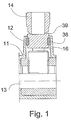
- Figure no. 1 shows a known clamping element with an O-ring (38) mounted on the outer surface, so that when the clamping element is screwed into the mouth (12) of a connector (11) to make an electrical contact with one or more electrical wires (13), this O-ring (38) rubs against the inner walls (16) of said mouth (12), thus making the electrical contact with said wire (13) faulty.
- the clamping element (10) is made up of a pre-mounted set comprising a tightening screw (17) mounted inside a tightening nut (19), a waterproofing joint (21) mounted in the lower part of the tightening nut (19), and two washers (22) mounted above and below the aforementioned waterproofing joint (21).
- the tightening screw (17) has a head (18) for the screwing of the same inside the mouth by the threaded part (15) until its lower base (35) butts up against an electrical wire(13), having a narrowing (39) between the body and the head (18) as a weakening surface (see figures no. 3 and 8), so that when this head (18) is screwed all the way in, it breaks at this point, as can be seen in figure no. 14.
- the tightening screw (17) has a screwing part (25) on the outer surface of its body intended to be screwed into the corresponding threaded part (26) of the inside surface of the tightening nut (19), thus joining the tightening nut (19) to the tightening screw (17).
- the tightening nut (19) has a head (20) to screw it against the waterproofing joint (21) placed under the lower base of the nut (19).
- the torque "P2" applied to the head (20) deforms the waterproofing joint (21) (making its height decrease from “e1” to “e2”) when it butts against said surface (36), and it necessarily contracts axially and consequently generates a radial force "p2" against the inner walls of the mouth, thus achieving a waterproof seal against the outside surface of the body of the tightening screw (17), see figure no. 15.
- the toe (23) can optionally have a toe (23) attached below to the tightening screw (17) by way of a threaded portion (27) on the lower part of the tightening screw (17) that screws into a corresponding interior threaded portion of the toe (23), the toe (23) having the function of making an electrical contact with the wire (13), see figures no. 2 to 9.
- the toe (23) has outside threading (29) for screwing in (15).
- the tightening nut (19), the waterproofing joint (21), the washers (22) and the toe (23) have their respective through-holes (30, 31, 32, 33) in an axial direction, (30, 31, 32), except hole (33), which is blind, see figure no. 9.
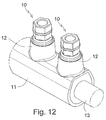
- Figures no. 10 to 12 show a possible version of a connector (11) with two mouths (12) in which the respective clamping elements (10) are starting to be mounted.
- Figure no. 13 shows the position of the introduction of the clamping element (10) into a mouth (12) of a connector (11) in the first assembly operation
- figure no. 14 shows the maximum screwing-in position of the clamping element (10) inside the mouth (12) of the connector (11) at the end of the first assembly operation in which an optimal axial force is applied downwards, "p1” causing the breaking of the head (18) of the tightening screw
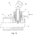
- figure no. 15 shows the maximum screwing-in position of the tightening nut (19) on the waterproofing joint (21) in the second assembly operation, causing the breaking of the head (20) of the tightening nut (19) and the generation of an optimal radial force, "p2" in the two directions that makes the closure totally waterproof.
Landscapes
- Connector Housings Or Holding Contact Members (AREA)
- Details Of Connecting Devices For Male And Female Coupling (AREA)
Abstract
Description
- More specifically, the invention refers to a pre-mounted clamping elements of the kind that are placed inside a mouth or hole placed crosswise in a connector, said connector consisting of a connecting element especially designed for clamping element one or more electrical wires that are entered lengthwise into it by way of one or more tightening elements.
- Connectors that allow splices, shunts, or terminations, preferably of metal, with a body that is tubular, generally cylindrical, are well-known. Usually they have one or more holes or bores that cross through the wall of said body in order to hold one or more electrical wires of the same or different diameters running lengthwise inside the connector still in the interior of the connector by way of their respective tightening elements.
- On the market there are a wide variety of mechanical screwing connectors that have a wide variety of types of screws to clamping element onto the wiring, entered into one or both ends of the electrical connector, among these, for example, Spanish patents
200502821 200600568 200600954 200602698 - In general, the clamping elements are intended to maintain a certain torque on the exterior part of the electrical wire in order to make an electrical connection with said wire. In order to achieve the function of electrically connecting the clamping elements with the wire, the clamping elements are designed so that when the foreseen torque is surpassed, they end up breaking, as there is a choking area, which is preferably ring-shaped, inside them that determines the torque force to be applied to the wire in the interior of the connector, where part of the element breaks.
- There are also some clamping elements configured with the additional function of ensuring a degree of waterproofing that is suitable for keeping fluids, such as water, from getting into the connector. This double function of the clamping elements currently presents technical difficulties, as known clamping elements are made up of a waterproof tightening screw held into the element like an O-ring, so that when the tightening screw is screwed into the mouth of a connector to make an electrical contact with the electrical wire, the waterproofing rubs against the inner walls of the mouth and this rubbing force means that when one tries to maximise the waterproofing, the axial pressure on the electrical wiring decreases, so that the electrical contact with said wire is made under conditions of less-than-normal torque transmission.
- Therefore, the aforementioned double function of the clamping elements can't be achieved under optimal conditions with the clamping elements known to date.
- The main aim of the present invention is to design a clamping element adapted to be mounted inside a mouth or hole placed crosswise in a connector, within which one or more electrical wires are placed, which on one hand makes optimal electrical contact between the clamping element and the electrical wire, and on the other hand, allows optimal waterproof tightening of the clamping element in the connector.
- Another aim of the present invention is to design a clamping element that can easily be mass produced with low manufacturing costs, so that later the system can be pre-mounted in a connector.
- Another aim of the present invention is to design a pre-mounted clamping element that can easily be assembled by a factory worker inside the mouth of a connector.
- The present invention consists of a pre-mounted clamping element of the kind placed inside of a mouth placed crosswise in a connector, inside of which one or more electrical wire(s) are placed, this mouth having a threaded part at the bottom for the threading to hold the clamping elements still.
- The pre-mounted clamping element of the invention is made up of a set that comprises:
- A means of tightening that is set up in such a way that when you act on it, it exercises a torque that is transmitted axially, and when this set comes up against the electrical wiring at its lower end, the torque applied, "P1," achieves an optimal electrical contact with said electrical wire; and
- Other tightening means that are arranged in such a way that, once this optimal electrical contact is made, when they are acted upon, a torque is transmitted in a radial direction against the lower walls of the mouth, and said "P2" torque is suitable for achieving optimal waterproofing of the clamping elements in said mouth of the connector.
- This particular configuration of the tightening element means that once it is pre-mounted, it can be placed in the mouth of a connector by way of two simple, consecutive actions, so that two different functions are fulfilled at the same time: on one hand there is an optimal electrical contact with the electrical wire, and on the other hand, there is optimal waterproof closing of the clamping elements in the mouth.
- Preferably the transmission of the radial torque of the set is made by way of a waterproof joint.
- According to a preferred practical version of the present invention, the pre-mounted tightening set comprises:
- a clamping element made up of a tightening screw with a head adapted to be screwed into the interior of the mouth until its lower end goes all the way against the electrical wire that runs through the interior of the connector and manages to exercise a certain axial torque, "P1," to make optimal electrical contact with the wire, and said tightening screw has a tightening nut; and
- other means of tightening made up of a tightening nut with a head adapted to be screwed onto a waterproof joint until this waterproof joint generates a radial pressure, "p2" that is suitable for making a waterproof closure against the inside walls of the upper part of the mouth.
- The axial pressure, "p1" of the tightening screw against the electrical wire is achieved by applying a "P1" torque on the head of the tightening screw in a first screwing operation.
- The "p2" radial pressure of the waterproofing joint against the inner walls of the mouth is achieved by applying a "P2" torque on the head of the tightening nut in a second screwing operation that is transmitted to the waterproofing joint, the lower part of which rests on the connector, so that said torque contracts the waterproof joint axially and thus generates a radial force "P2" against the inner walls of the mouth, making a waterproof seal.
- The means of holding the tightening nut on the tightening screw can be a threaded part foreseen on the exterior surface of the tightening screw and the corresponding coaxial threaded part of the interior surface of the nut.
- Both the tightening screw and the tightening nut include a means of weakening between their respective bodies and heads, so that when the aforementioned heads are screwed all the way in, they break by way of said weakening mechanism.
- Optionally, the pre-mounted set can include two tightening washers placed above and below the waterproofing joint, made to press on the joint above and below said joint, respectively.
- The lower part of the pre-mounted set may optionally include a toe attached to the tightening screw and adapted to make an electrical contact with the wire, this piece being adapted to the material and/or type of each conductor so as to make an optimal electrical contact of metal against metal, due to the great variety of materials (for example, aluminium or copper) and types of wires (solid, flexible, etc.).
- The pre-mounted set may optionally include an O-ring in the tightening nut, in order to improve the waterproofing of the tightening set.
- Other details and features will be shown in the course of the description provided, referring to the drawings that accompany this report, which show the invention, although it is not limited to them, keeping in mind that the versions of the invention can be made in any material, in reference to the composition, as well as the non-critical outside configuration.
- Below is a list of the different parts of the invention which are found on the diagrams and which can be located using the following numbers; (10, 10', 10") clamping element, (11) connector, (12) mouth of the connector, (13) electrical wire, (14) known clamping element, (15) threaded part of the mouth, (16) inner walls of the mouth, (17) tightening screw, (18) head of the tightening screw, (19) tightening nut, (20) head of the tightening nut, (21) waterproofing joint, (22) tightening washers, (23) toe, (24) O-ring, (25) upper, outer threaded part of the tightening screw, (26) inner threaded part of the nut, (27) lower, outer threaded part of the tightening screw, (28) inner threaded part of the toe, (29) outer threaded part of the toe, (30) through-hole of the tightening nut, (31) through-hole of the washer, (32) through-hole of the waterproofing joint, (33) blind hole of the toe, (35) lower base of the toe, (36) butting surface of the mouth, (37) lower base of the lower washer, (38) O-ring, (39) inner walls of the mouth, (39) narrowing in the tightening screw, (40) narrowing in the tightening nut.
- In the figures:
- Figure no. 1 shows a frontal view of a conventional clamping element mounted crosswise in a connector, specifically screwed into one of its mouths to make an electrical contact with an electrical wire.
- Figure no. 2 shows a side view of the tightening element (10) of the invention.
- Figure no. 3 shows a sectioned side view of A-A' of the clamping elements (10) of the invention.
- Figure no. 4 shows a view of the clamping element (10) of the invention as seen from above.
- Figure no. 5 shows a view of the tightening element (10) of the invention from below.
- Figure no. 6 shows a frontal view of the clamping element (10) of the invention.
- Figure no. 7 shows the same side view of the clamping element (10) of the invention as figure no. 2, but with the parts separated.
- Figure no. 8 shows the same sectioned side view of the clamping element (10) of the invention as figure no. 3, but with the parts separated.
- Figure no. 9 shows the same frontal view of the clamping element (10) of the invention as figure no. 6, but with the parts separated.
- Figure no. 10 shows a side view of the two clamping elements (10) which are starting to be mounted crosswise in the respective mouths (12) of a connector (11).
- Figure no. 11 shows a sectioned frontal view of C-C' of the two clamping elements (10) of figure no. 10.
- Figure no. 12 shows a frontal view of the two clamping elements (10) of figure no. 10.
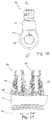
- Figures no. 13 to 15 show sectioned raised frontal views of the various consecutive positions of the assembly of a clamping element (10, 10', 10") in the mouth (12) of a connector (11).
- Figure no. 1 shows a known clamping element with an O-ring (38) mounted on the outer surface, so that when the clamping element is screwed into the mouth (12) of a connector (11) to make an electrical contact with one or more electrical wires (13), this O-ring (38) rubs against the inner walls (16) of said mouth (12), thus making the electrical contact with said wire (13) faulty.
- In one of the preferred versions of the invention, and as can be seen in the attached figures no. 2 to 9, the clamping element (10) is made up of a pre-mounted set comprising a tightening screw (17) mounted inside a tightening nut (19), a waterproofing joint (21) mounted in the lower part of the tightening nut (19), and two washers (22) mounted above and below the aforementioned waterproofing joint (21).
- The tightening screw (17) has a head (18) for the screwing of the same inside the mouth by the threaded part (15) until its lower base (35) butts up against an electrical wire(13), having a narrowing (39) between the body and the head (18) as a weakening surface (see figures no. 3 and 8), so that when this head (18) is screwed all the way in, it breaks at this point, as can be seen in figure no. 14. On the other hand, the tightening screw (17) has a screwing part (25) on the outer surface of its body intended to be screwed into the corresponding threaded part (26) of the inside surface of the tightening nut (19), thus joining the tightening nut (19) to the tightening screw (17).
- On its part, the tightening nut (19) has a head (20) to screw it against the waterproofing joint (21) placed under the lower base of the nut (19). The waterproofing joint (21), along with both washers (22), mounted above and underneath said waterproofing joint (21), all have an upper diameter that is greater than the diameter of the lower part of the tightening screw (17), so that in the second operation of tightening of the head (20) of the tightening nut (19), the lower washer (20) has its lower base (37) resting on a butting surface (36) of the mouth (12) of the connector (11). Therefore, the torque "P2" applied to the head (20) deforms the waterproofing joint (21) (making its height decrease from "e1" to "e2") when it butts against said surface (36), and it necessarily contracts axially and consequently generates a radial force "p2" against the inner walls of the mouth, thus achieving a waterproof seal against the outside surface of the body of the tightening screw (17), see figure no. 15.
- It can optionally have a toe (23) attached below to the tightening screw (17) by way of a threaded portion (27) on the lower part of the tightening screw (17) that screws into a corresponding interior threaded portion of the toe (23), the toe (23) having the function of making an electrical contact with the wire (13), see figures no. 2 to 9. The toe (23) has outside threading (29) for screwing in (15).
- There can also be an O-ring (24) in the tightening nut (19) to improve the waterproofing of the clamping element (10), see figures no. 2 to 9.
- In order to allow the body of the tightening screw (17) to pass through, the tightening nut (19), the waterproofing joint (21), the washers (22) and the toe (23) have their respective through-holes (30, 31, 32, 33) in an axial direction, (30, 31, 32), except hole (33), which is blind, see figure no. 9.
- Figures no. 10 to 12 show a possible version of a connector (11) with two mouths (12) in which the respective clamping elements (10) are starting to be mounted.
- Figure no. 13 shows the position of the introduction of the clamping element (10) into a mouth (12) of a connector (11) in the first assembly operation, figure no. 14 shows the maximum screwing-in position of the clamping element (10) inside the mouth (12) of the connector (11) at the end of the first assembly operation in which an optimal axial force is applied downwards, "p1" causing the breaking of the head (18) of the tightening screw, and, lastly, figure no. 15 shows the maximum screwing-in position of the tightening nut (19) on the waterproofing joint (21) in the second assembly operation, causing the breaking of the head (20) of the tightening nut (19) and the generation of an optimal radial force, "p2" in the two directions that makes the closure totally waterproof.
- Having described the present invention in correspondence to the attached figures, it is easy to understand that any changes can be made in the details that are considered convenient, as long as they don't change the essence of the invention, which is summarised in the following claims.
Claims (7)
- "Clamping element" of the kind that are mounted inside of a mouth placed crosswise in a connector inside of which there is at least one electrical wire, the mouth having a threaded inside part for screwing in the clamping element, characterised in that it is made up of a set that comprises:A clamping element that is configured such that when acted upon, a torque is exercised that transmits axially and when the bottom end of the set goes all the way in against the electrical wire, the applied torque, "P1" achieves optimal electrical contact with said electrical wire; andAnother clamping element that is configured so that once said optimal electrical contact is made, when it is acted upon, a torque is exercised that is transmitted in a radial direction against the inner walls of the mouth, and said torque, "P2," is suitable for achieving an optimal waterproof closing of the clamping element in said mouth of the connector.
- "Clamping element" according to the first claim, characterised in that the transmission of the radial torque of the set is achieved through a waterproofing joint.
- "Clamping element" according to the first and second claims, characterised in that the set comprises:A means of tightening made up of a tightening screw with a head adapted to be screwed inside the mouth until the lower end butts up against the electrical wire that runs through the inside of the connector and it manages to exercise a certain axial torque, "P1" to make an optimal electrical contact with aforementioned wire, and this tightening screw has a way to hold a tightening nut; andAnother clamping elements made up of the tightening nut with a head adapted to be screwed onto a waterproofing joint until it generates a radial pressure, "P2" that is suitable for making a waterproof seal against the inner walls of the upper part of the mouth.
- "Clamping element" according to any of the previous claims, characterised in that it has a toe in the lower part held to the tightening screw and adapted to make an electrical contact with the electrical wire.
- "Clamping element" according to the third claim, characterised in that the means that the tightening screw has of holding the nut is a threaded part on the outer surface of the tightening screw and the corresponding threaded part on the inside surface of the nut.
- "Clamping element" according to any of the previous claims, characterised in that the tightening screw has a means of weakening between its body and its head, so that when the aforementioned head is screwed all the way in, it breaks due to this weakening system.
- "Clamping element" according to any of the previous claims, characterised in that the tightening nut comprises a means of weakening between its body and its head, so that when the aforementioned head is screwed all the way in, it breaks due to this weakening system.
Applications Claiming Priority (1)
| Application Number | Priority Date | Filing Date | Title |
|---|---|---|---|
| PCT/ES2013/070843 WO2015082729A1 (en) | 2013-12-04 | 2013-12-04 | Clamping element |
Publications (3)
| Publication Number | Publication Date |
|---|---|
| EP3079206A1 true EP3079206A1 (en) | 2016-10-12 |
| EP3079206A4 EP3079206A4 (en) | 2017-06-07 |
| EP3079206B1 EP3079206B1 (en) | 2020-04-01 |
Family
ID=53272933
Family Applications (1)
| Application Number | Title | Priority Date | Filing Date |
|---|---|---|---|
| EP13898543.7A Active EP3079206B1 (en) | 2013-12-04 | 2013-12-04 | Clamping element |
Country Status (3)
| Country | Link |
|---|---|
| EP (1) | EP3079206B1 (en) |
| ES (1) | ES2798188T3 (en) |
| WO (1) | WO2015082729A1 (en) |
Family Cites Families (16)
| Publication number | Priority date | Publication date | Assignee | Title |
|---|---|---|---|---|
| US4170163A (en) * | 1977-07-27 | 1979-10-09 | Modulus Corporation | Visual indicator |
| US4734061A (en) * | 1986-12-31 | 1988-03-29 | Bell Communications Research, Inc. | Telecommunications terminal block |
| EP1099892A1 (en) * | 1999-11-09 | 2001-05-16 | Witzenmann GmbH Metallschlauch-Fabrik Pforzheim | Sealing between components having co - axial, axial-symetrically cross - section to one another |
| ES2300169B1 (en) | 2005-11-17 | 2009-03-01 | Ridelin, S.L. | INSULATION SYSTEM FOR THE EXTREME OF ELECTRICAL CABLES. |
| CA2532289C (en) * | 2006-01-06 | 2009-10-27 | Thomas & Betts International, Inc. | Insulated water-tight connector assembly including a set screw driver and plug |
| ES2283219B1 (en) | 2006-04-12 | 2008-09-16 | Ridelin S.L. | SCREW FOR ELECTRICAL CONNECTORS. |
| ES2281291B1 (en) | 2006-03-08 | 2008-06-01 | Ridelin S.L. | PERFECTED SCREW FOR ELECTRICAL CONNECTORS. |
| BRPI0703433B1 (en) * | 2006-03-08 | 2018-05-08 | Ridelin Sl | screws for electrical connectors |
| GB2443001A (en) * | 2006-10-21 | 2008-04-23 | Tyco Electronics Ltd Uk | Bolt having extending contact tip |
| ES2318998B1 (en) | 2006-10-24 | 2009-12-17 | Ridelin S.L. | MECHANICAL CONNECTOR WITH INCORPORATED CABLE CENTER. |
| FR2907859B1 (en) * | 2006-10-30 | 2008-12-19 | Tyco Electronics Simel Soc Par | SCREW ASSEMBLY WITH PROGRAM BREAK |
| AU2009200994B2 (en) * | 2008-04-29 | 2014-11-06 | Tyco Electronics Energy Pty Ltd | Installation Monitoring for Connectors |
| FR2958459B1 (en) * | 2010-04-06 | 2012-10-12 | Soreca | TIGHTENING DEVICE WITH A HEADABLE HEAD FOR AN ELECTRICAL COUPLING SLEEVE |
| EP2381535B1 (en) * | 2010-04-26 | 2015-03-04 | Nexans | Assembly for fixing an electric conductor in a clamp |
| CN102163777A (en) * | 2010-11-22 | 2011-08-24 | 苏州华旃航天电器有限公司 | Lock bolt of O-shaped seal ring of connector |
| PL2498338T3 (en) * | 2011-03-11 | 2014-05-30 | Nexans | Assembly with a terminal executed as tubular piece of metal and at least one clamping screw |
-
2013
- 2013-12-04 EP EP13898543.7A patent/EP3079206B1/en active Active
- 2013-12-04 WO PCT/ES2013/070843 patent/WO2015082729A1/en not_active Ceased
- 2013-12-04 ES ES13898543T patent/ES2798188T3/en active Active
Also Published As
| Publication number | Publication date |
|---|---|
| EP3079206A4 (en) | 2017-06-07 |
| WO2015082729A1 (en) | 2015-06-11 |
| ES2798188T3 (en) | 2020-12-09 |
| EP3079206B1 (en) | 2020-04-01 |
Similar Documents
| Publication | Publication Date | Title |
|---|---|---|
| EP1833117B1 (en) | A screw for electric connectors | |
| CN103522255B (en) | A kind of Automatic tightener of stud | |
| AU2013283890A1 (en) | Shearable screw, associated system and device for screw-connecting electrical conductors with such a shearable screw | |
| US20160322715A1 (en) | Torque limited screw for electrical connector | |
| WO2008042763A3 (en) | Coaxial cable connector with threaded post | |
| WO2008047119A8 (en) | A bolt for use in an electrical connector | |
| WO2007089427A3 (en) | Threaded pipe connection | |
| US10135157B2 (en) | Binding screw for a wire connection assembly and wire connection assembly | |
| CA2618334A1 (en) | Electrical wiring | |
| KR100881353B1 (en) | Cable clamping device for power transmission | |
| US1597169A (en) | Ground-pipe fitting | |
| EP3079206B1 (en) | Clamping element | |
| DE102019205887A1 (en) | Connection socket for a control unit | |
| KR100611574B1 (en) | Outlet plug and plug with waterproof structure | |
| AU2014253570A1 (en) | Conductor Contact Tip | |
| DE102016218179A1 (en) | Capacitive proximity sensor | |
| DE102011106736A1 (en) | Housing connector for use with housing socket for connecting e.g. antenna to housing of radio, has plug body comprising engagement recesses that axially extend to circulating bar such that recesses are arranged at outer-side of bar | |
| KR200384747Y1 (en) | Pressure switch | |
| KR20170066804A (en) | Nipple for connecting hose | |
| EP2407676A1 (en) | Structure of a build-in screw in a bushing and corresponding sensor housing | |
| US982563A (en) | Terminal or lug for electrical conductors. | |
| CN212968281U (en) | Cable waterproof joint | |
| KR200384746Y1 (en) | Pressure switch | |
| DE102012222803B4 (en) | Cover for a light module and light module | |
| KR200431684Y1 (en) | Pipe connecting joint for a play apparatus |
Legal Events
| Date | Code | Title | Description |
|---|---|---|---|
| PUAI | Public reference made under article 153(3) epc to a published international application that has entered the european phase |
Free format text: ORIGINAL CODE: 0009012 |
|
| 17P | Request for examination filed |
Effective date: 20160331 |
|
| AK | Designated contracting states |
Kind code of ref document: A1 Designated state(s): AL AT BE BG CH CY CZ DE DK EE ES FI FR GB GR HR HU IE IS IT LI LT LU LV MC MK MT NL NO PL PT RO RS SE SI SK SM TR |
|
| AX | Request for extension of the european patent |
Extension state: BA ME |
|
| DAX | Request for extension of the european patent (deleted) | ||
| A4 | Supplementary search report drawn up and despatched |
Effective date: 20170509 |
|
| RIC1 | Information provided on ipc code assigned before grant |
Ipc: H01R 4/36 20060101AFI20170502BHEP Ipc: F16B 31/02 20060101ALI20170502BHEP Ipc: F16J 15/24 20060101ALI20170502BHEP Ipc: H01R 13/52 20060101ALI20170502BHEP Ipc: F16L 21/04 20060101ALI20170502BHEP |
|
| STAA | Information on the status of an ep patent application or granted ep patent |
Free format text: STATUS: EXAMINATION IS IN PROGRESS |
|
| 17Q | First examination report despatched |
Effective date: 20180604 |
|
| GRAP | Despatch of communication of intention to grant a patent |
Free format text: ORIGINAL CODE: EPIDOSNIGR1 |
|
| STAA | Information on the status of an ep patent application or granted ep patent |
Free format text: STATUS: GRANT OF PATENT IS INTENDED |
|
| INTG | Intention to grant announced |
Effective date: 20191111 |
|
| GRAS | Grant fee paid |
Free format text: ORIGINAL CODE: EPIDOSNIGR3 |
|
| GRAA | (expected) grant |
Free format text: ORIGINAL CODE: 0009210 |
|
| STAA | Information on the status of an ep patent application or granted ep patent |
Free format text: STATUS: THE PATENT HAS BEEN GRANTED |
|
| AK | Designated contracting states |
Kind code of ref document: B1 Designated state(s): AL AT BE BG CH CY CZ DE DK EE ES FI FR GB GR HR HU IE IS IT LI LT LU LV MC MK MT NL NO PL PT RO RS SE SI SK SM TR |
|
| REG | Reference to a national code |
Ref country code: GB Ref legal event code: FG4D |
|
| REG | Reference to a national code |
Ref country code: AT Ref legal event code: REF Ref document number: 1252579 Country of ref document: AT Kind code of ref document: T Effective date: 20200415 Ref country code: CH Ref legal event code: EP |
|
| REG | Reference to a national code |
Ref country code: DE Ref legal event code: R096 Ref document number: 602013067562 Country of ref document: DE |
|
| REG | Reference to a national code |
Ref country code: IE Ref legal event code: FG4D |
|
| PG25 | Lapsed in a contracting state [announced via postgrant information from national office to epo] |
Ref country code: BG Free format text: LAPSE BECAUSE OF FAILURE TO SUBMIT A TRANSLATION OF THE DESCRIPTION OR TO PAY THE FEE WITHIN THE PRESCRIBED TIME-LIMIT Effective date: 20200701 |
|
| REG | Reference to a national code |
Ref country code: NL Ref legal event code: MP Effective date: 20200401 |
|
| REG | Reference to a national code |
Ref country code: LT Ref legal event code: MG4D |
|
| PG25 | Lapsed in a contracting state [announced via postgrant information from national office to epo] |
Ref country code: SE Free format text: LAPSE BECAUSE OF FAILURE TO SUBMIT A TRANSLATION OF THE DESCRIPTION OR TO PAY THE FEE WITHIN THE PRESCRIBED TIME-LIMIT Effective date: 20200401 Ref country code: LT Free format text: LAPSE BECAUSE OF FAILURE TO SUBMIT A TRANSLATION OF THE DESCRIPTION OR TO PAY THE FEE WITHIN THE PRESCRIBED TIME-LIMIT Effective date: 20200401 Ref country code: NL Free format text: LAPSE BECAUSE OF FAILURE TO SUBMIT A TRANSLATION OF THE DESCRIPTION OR TO PAY THE FEE WITHIN THE PRESCRIBED TIME-LIMIT Effective date: 20200401 Ref country code: CZ Free format text: LAPSE BECAUSE OF FAILURE TO SUBMIT A TRANSLATION OF THE DESCRIPTION OR TO PAY THE FEE WITHIN THE PRESCRIBED TIME-LIMIT Effective date: 20200401 Ref country code: IS Free format text: LAPSE BECAUSE OF FAILURE TO SUBMIT A TRANSLATION OF THE DESCRIPTION OR TO PAY THE FEE WITHIN THE PRESCRIBED TIME-LIMIT Effective date: 20200801 Ref country code: PT Free format text: LAPSE BECAUSE OF FAILURE TO SUBMIT A TRANSLATION OF THE DESCRIPTION OR TO PAY THE FEE WITHIN THE PRESCRIBED TIME-LIMIT Effective date: 20200817 Ref country code: FI Free format text: LAPSE BECAUSE OF FAILURE TO SUBMIT A TRANSLATION OF THE DESCRIPTION OR TO PAY THE FEE WITHIN THE PRESCRIBED TIME-LIMIT Effective date: 20200401 Ref country code: NO Free format text: LAPSE BECAUSE OF FAILURE TO SUBMIT A TRANSLATION OF THE DESCRIPTION OR TO PAY THE FEE WITHIN THE PRESCRIBED TIME-LIMIT Effective date: 20200701 Ref country code: GR Free format text: LAPSE BECAUSE OF FAILURE TO SUBMIT A TRANSLATION OF THE DESCRIPTION OR TO PAY THE FEE WITHIN THE PRESCRIBED TIME-LIMIT Effective date: 20200702 |
|
| REG | Reference to a national code |
Ref country code: AT Ref legal event code: MK05 Ref document number: 1252579 Country of ref document: AT Kind code of ref document: T Effective date: 20200401 |
|
| PG25 | Lapsed in a contracting state [announced via postgrant information from national office to epo] |
Ref country code: RS Free format text: LAPSE BECAUSE OF FAILURE TO SUBMIT A TRANSLATION OF THE DESCRIPTION OR TO PAY THE FEE WITHIN THE PRESCRIBED TIME-LIMIT Effective date: 20200401 Ref country code: HR Free format text: LAPSE BECAUSE OF FAILURE TO SUBMIT A TRANSLATION OF THE DESCRIPTION OR TO PAY THE FEE WITHIN THE PRESCRIBED TIME-LIMIT Effective date: 20200401 Ref country code: LV Free format text: LAPSE BECAUSE OF FAILURE TO SUBMIT A TRANSLATION OF THE DESCRIPTION OR TO PAY THE FEE WITHIN THE PRESCRIBED TIME-LIMIT Effective date: 20200401 |
|
| REG | Reference to a national code |
Ref country code: ES Ref legal event code: FG2A Ref document number: 2798188 Country of ref document: ES Kind code of ref document: T3 Effective date: 20201209 |
|
| PG25 | Lapsed in a contracting state [announced via postgrant information from national office to epo] |
Ref country code: AL Free format text: LAPSE BECAUSE OF FAILURE TO SUBMIT A TRANSLATION OF THE DESCRIPTION OR TO PAY THE FEE WITHIN THE PRESCRIBED TIME-LIMIT Effective date: 20200401 |
|
| REG | Reference to a national code |
Ref country code: DE Ref legal event code: R097 Ref document number: 602013067562 Country of ref document: DE |
|
| PG25 | Lapsed in a contracting state [announced via postgrant information from national office to epo] |
Ref country code: SM Free format text: LAPSE BECAUSE OF FAILURE TO SUBMIT A TRANSLATION OF THE DESCRIPTION OR TO PAY THE FEE WITHIN THE PRESCRIBED TIME-LIMIT Effective date: 20200401 Ref country code: AT Free format text: LAPSE BECAUSE OF FAILURE TO SUBMIT A TRANSLATION OF THE DESCRIPTION OR TO PAY THE FEE WITHIN THE PRESCRIBED TIME-LIMIT Effective date: 20200401 Ref country code: EE Free format text: LAPSE BECAUSE OF FAILURE TO SUBMIT A TRANSLATION OF THE DESCRIPTION OR TO PAY THE FEE WITHIN THE PRESCRIBED TIME-LIMIT Effective date: 20200401 Ref country code: IT Free format text: LAPSE BECAUSE OF FAILURE TO SUBMIT A TRANSLATION OF THE DESCRIPTION OR TO PAY THE FEE WITHIN THE PRESCRIBED TIME-LIMIT Effective date: 20200401 Ref country code: DK Free format text: LAPSE BECAUSE OF FAILURE TO SUBMIT A TRANSLATION OF THE DESCRIPTION OR TO PAY THE FEE WITHIN THE PRESCRIBED TIME-LIMIT Effective date: 20200401 Ref country code: RO Free format text: LAPSE BECAUSE OF FAILURE TO SUBMIT A TRANSLATION OF THE DESCRIPTION OR TO PAY THE FEE WITHIN THE PRESCRIBED TIME-LIMIT Effective date: 20200401 |
|
| PLBE | No opposition filed within time limit |
Free format text: ORIGINAL CODE: 0009261 |
|
| STAA | Information on the status of an ep patent application or granted ep patent |
Free format text: STATUS: NO OPPOSITION FILED WITHIN TIME LIMIT |
|
| PG25 | Lapsed in a contracting state [announced via postgrant information from national office to epo] |
Ref country code: SK Free format text: LAPSE BECAUSE OF FAILURE TO SUBMIT A TRANSLATION OF THE DESCRIPTION OR TO PAY THE FEE WITHIN THE PRESCRIBED TIME-LIMIT Effective date: 20200401 Ref country code: PL Free format text: LAPSE BECAUSE OF FAILURE TO SUBMIT A TRANSLATION OF THE DESCRIPTION OR TO PAY THE FEE WITHIN THE PRESCRIBED TIME-LIMIT Effective date: 20200401 |
|
| 26N | No opposition filed |
Effective date: 20210112 |
|
| PG25 | Lapsed in a contracting state [announced via postgrant information from national office to epo] |
Ref country code: SI Free format text: LAPSE BECAUSE OF FAILURE TO SUBMIT A TRANSLATION OF THE DESCRIPTION OR TO PAY THE FEE WITHIN THE PRESCRIBED TIME-LIMIT Effective date: 20200401 |
|
| REG | Reference to a national code |
Ref country code: DE Ref legal event code: R119 Ref document number: 602013067562 Country of ref document: DE |
|
| REG | Reference to a national code |
Ref country code: CH Ref legal event code: PL |
|
| GBPC | Gb: european patent ceased through non-payment of renewal fee |
Effective date: 20201204 |
|
| PG25 | Lapsed in a contracting state [announced via postgrant information from national office to epo] |
Ref country code: MC Free format text: LAPSE BECAUSE OF FAILURE TO SUBMIT A TRANSLATION OF THE DESCRIPTION OR TO PAY THE FEE WITHIN THE PRESCRIBED TIME-LIMIT Effective date: 20200401 |
|
| REG | Reference to a national code |
Ref country code: BE Ref legal event code: MM Effective date: 20201231 |
|
| PG25 | Lapsed in a contracting state [announced via postgrant information from national office to epo] |
Ref country code: IE Free format text: LAPSE BECAUSE OF NON-PAYMENT OF DUE FEES Effective date: 20201204 Ref country code: FR Free format text: LAPSE BECAUSE OF NON-PAYMENT OF DUE FEES Effective date: 20201231 Ref country code: LU Free format text: LAPSE BECAUSE OF NON-PAYMENT OF DUE FEES Effective date: 20201204 |
|
| PG25 | Lapsed in a contracting state [announced via postgrant information from national office to epo] |
Ref country code: GB Free format text: LAPSE BECAUSE OF NON-PAYMENT OF DUE FEES Effective date: 20201204 Ref country code: DE Free format text: LAPSE BECAUSE OF NON-PAYMENT OF DUE FEES Effective date: 20210701 Ref country code: CH Free format text: LAPSE BECAUSE OF NON-PAYMENT OF DUE FEES Effective date: 20201231 Ref country code: LI Free format text: LAPSE BECAUSE OF NON-PAYMENT OF DUE FEES Effective date: 20201231 |
|
| PG25 | Lapsed in a contracting state [announced via postgrant information from national office to epo] |
Ref country code: TR Free format text: LAPSE BECAUSE OF FAILURE TO SUBMIT A TRANSLATION OF THE DESCRIPTION OR TO PAY THE FEE WITHIN THE PRESCRIBED TIME-LIMIT Effective date: 20200401 Ref country code: MT Free format text: LAPSE BECAUSE OF FAILURE TO SUBMIT A TRANSLATION OF THE DESCRIPTION OR TO PAY THE FEE WITHIN THE PRESCRIBED TIME-LIMIT Effective date: 20200401 Ref country code: CY Free format text: LAPSE BECAUSE OF FAILURE TO SUBMIT A TRANSLATION OF THE DESCRIPTION OR TO PAY THE FEE WITHIN THE PRESCRIBED TIME-LIMIT Effective date: 20200401 |
|
| PG25 | Lapsed in a contracting state [announced via postgrant information from national office to epo] |
Ref country code: MK Free format text: LAPSE BECAUSE OF FAILURE TO SUBMIT A TRANSLATION OF THE DESCRIPTION OR TO PAY THE FEE WITHIN THE PRESCRIBED TIME-LIMIT Effective date: 20200401 |
|
| PG25 | Lapsed in a contracting state [announced via postgrant information from national office to epo] |
Ref country code: BE Free format text: LAPSE BECAUSE OF NON-PAYMENT OF DUE FEES Effective date: 20201231 |
|
| PG25 | Lapsed in a contracting state [announced via postgrant information from national office to epo] |
Ref country code: IS Free format text: LAPSE BECAUSE OF NON-PAYMENT OF DUE FEES Effective date: 20200801 |
|
| PGFP | Annual fee paid to national office [announced via postgrant information from national office to epo] |
Ref country code: ES Payment date: 20260203 Year of fee payment: 13 |