EP3079054B1 - Method and apparatus for data access - Google Patents
Method and apparatus for data access Download PDFInfo
- Publication number
- EP3079054B1 EP3079054B1 EP14878327.7A EP14878327A EP3079054B1 EP 3079054 B1 EP3079054 B1 EP 3079054B1 EP 14878327 A EP14878327 A EP 14878327A EP 3079054 B1 EP3079054 B1 EP 3079054B1
- Authority
- EP
- European Patent Office
- Prior art keywords
- state
- stripe
- read
- data
- disk
- Prior art date
- Legal status (The legal status is an assumption and is not a legal conclusion. Google has not performed a legal analysis and makes no representation as to the accuracy of the status listed.)
- Active
Links
Images


Classifications
-
- G—PHYSICS
- G06—COMPUTING OR CALCULATING; COUNTING
- G06F—ELECTRIC DIGITAL DATA PROCESSING
- G06F3/00—Input arrangements for transferring data to be processed into a form capable of being handled by the computer; Output arrangements for transferring data from processing unit to output unit, e.g. interface arrangements
- G06F3/06—Digital input from, or digital output to, record carriers, e.g. RAID, emulated record carriers or networked record carriers
- G06F3/0601—Interfaces specially adapted for storage systems
- G06F3/0602—Interfaces specially adapted for storage systems specifically adapted to achieve a particular effect
- G06F3/0614—Improving the reliability of storage systems
- G06F3/0619—Improving the reliability of storage systems in relation to data integrity, e.g. data losses, bit errors
-
- G—PHYSICS
- G06—COMPUTING OR CALCULATING; COUNTING
- G06F—ELECTRIC DIGITAL DATA PROCESSING
- G06F3/00—Input arrangements for transferring data to be processed into a form capable of being handled by the computer; Output arrangements for transferring data from processing unit to output unit, e.g. interface arrangements
- G06F3/06—Digital input from, or digital output to, record carriers, e.g. RAID, emulated record carriers or networked record carriers
- G06F3/0601—Interfaces specially adapted for storage systems
- G06F3/0628—Interfaces specially adapted for storage systems making use of a particular technique
- G06F3/0653—Monitoring storage devices or systems
-
- G—PHYSICS
- G06—COMPUTING OR CALCULATING; COUNTING
- G06F—ELECTRIC DIGITAL DATA PROCESSING
- G06F11/00—Error detection; Error correction; Monitoring
- G06F11/07—Responding to the occurrence of a fault, e.g. fault tolerance
- G06F11/08—Error detection or correction by redundancy in data representation, e.g. by using checking codes
- G06F11/10—Adding special bits or symbols to the coded information, e.g. parity check, casting out 9's or 11's
-
- G—PHYSICS
- G06—COMPUTING OR CALCULATING; COUNTING
- G06F—ELECTRIC DIGITAL DATA PROCESSING
- G06F11/00—Error detection; Error correction; Monitoring
- G06F11/07—Responding to the occurrence of a fault, e.g. fault tolerance
- G06F11/08—Error detection or correction by redundancy in data representation, e.g. by using checking codes
- G06F11/10—Adding special bits or symbols to the coded information, e.g. parity check, casting out 9's or 11's
- G06F11/1076—Parity data used in redundant arrays of independent storages, e.g. in RAID systems
-
- G—PHYSICS
- G06—COMPUTING OR CALCULATING; COUNTING
- G06F—ELECTRIC DIGITAL DATA PROCESSING
- G06F12/00—Accessing, addressing or allocating within memory systems or architectures
- G06F12/16—Protection against loss of memory contents
-
- G—PHYSICS
- G06—COMPUTING OR CALCULATING; COUNTING
- G06F—ELECTRIC DIGITAL DATA PROCESSING
- G06F3/00—Input arrangements for transferring data to be processed into a form capable of being handled by the computer; Output arrangements for transferring data from processing unit to output unit, e.g. interface arrangements
- G06F3/06—Digital input from, or digital output to, record carriers, e.g. RAID, emulated record carriers or networked record carriers
-
- G—PHYSICS
- G06—COMPUTING OR CALCULATING; COUNTING
- G06F—ELECTRIC DIGITAL DATA PROCESSING
- G06F3/00—Input arrangements for transferring data to be processed into a form capable of being handled by the computer; Output arrangements for transferring data from processing unit to output unit, e.g. interface arrangements
- G06F3/06—Digital input from, or digital output to, record carriers, e.g. RAID, emulated record carriers or networked record carriers
- G06F3/0601—Interfaces specially adapted for storage systems
- G06F3/0602—Interfaces specially adapted for storage systems specifically adapted to achieve a particular effect
- G06F3/0604—Improving or facilitating administration, e.g. storage management
-
- G—PHYSICS
- G06—COMPUTING OR CALCULATING; COUNTING
- G06F—ELECTRIC DIGITAL DATA PROCESSING
- G06F3/00—Input arrangements for transferring data to be processed into a form capable of being handled by the computer; Output arrangements for transferring data from processing unit to output unit, e.g. interface arrangements
- G06F3/06—Digital input from, or digital output to, record carriers, e.g. RAID, emulated record carriers or networked record carriers
- G06F3/0601—Interfaces specially adapted for storage systems
- G06F3/0602—Interfaces specially adapted for storage systems specifically adapted to achieve a particular effect
- G06F3/061—Improving I/O performance
-
- G—PHYSICS
- G06—COMPUTING OR CALCULATING; COUNTING
- G06F—ELECTRIC DIGITAL DATA PROCESSING
- G06F3/00—Input arrangements for transferring data to be processed into a form capable of being handled by the computer; Output arrangements for transferring data from processing unit to output unit, e.g. interface arrangements
- G06F3/06—Digital input from, or digital output to, record carriers, e.g. RAID, emulated record carriers or networked record carriers
- G06F3/0601—Interfaces specially adapted for storage systems
- G06F3/0628—Interfaces specially adapted for storage systems making use of a particular technique
- G06F3/0629—Configuration or reconfiguration of storage systems
- G06F3/0634—Configuration or reconfiguration of storage systems by changing the state or mode of one or more devices
-
- G—PHYSICS
- G06—COMPUTING OR CALCULATING; COUNTING
- G06F—ELECTRIC DIGITAL DATA PROCESSING
- G06F3/00—Input arrangements for transferring data to be processed into a form capable of being handled by the computer; Output arrangements for transferring data from processing unit to output unit, e.g. interface arrangements
- G06F3/06—Digital input from, or digital output to, record carriers, e.g. RAID, emulated record carriers or networked record carriers
- G06F3/0601—Interfaces specially adapted for storage systems
- G06F3/0628—Interfaces specially adapted for storage systems making use of a particular technique
- G06F3/0638—Organizing or formatting or addressing of data
- G06F3/064—Management of blocks
-
- G—PHYSICS
- G06—COMPUTING OR CALCULATING; COUNTING
- G06F—ELECTRIC DIGITAL DATA PROCESSING
- G06F3/00—Input arrangements for transferring data to be processed into a form capable of being handled by the computer; Output arrangements for transferring data from processing unit to output unit, e.g. interface arrangements
- G06F3/06—Digital input from, or digital output to, record carriers, e.g. RAID, emulated record carriers or networked record carriers
- G06F3/0601—Interfaces specially adapted for storage systems
- G06F3/0628—Interfaces specially adapted for storage systems making use of a particular technique
- G06F3/0655—Vertical data movement, i.e. input-output transfer; data movement between one or more hosts and one or more storage devices
- G06F3/0659—Command handling arrangements, e.g. command buffers, queues, command scheduling
-
- G—PHYSICS
- G06—COMPUTING OR CALCULATING; COUNTING
- G06F—ELECTRIC DIGITAL DATA PROCESSING
- G06F3/00—Input arrangements for transferring data to be processed into a form capable of being handled by the computer; Output arrangements for transferring data from processing unit to output unit, e.g. interface arrangements
- G06F3/06—Digital input from, or digital output to, record carriers, e.g. RAID, emulated record carriers or networked record carriers
- G06F3/0601—Interfaces specially adapted for storage systems
- G06F3/0668—Interfaces specially adapted for storage systems adopting a particular infrastructure
- G06F3/0671—In-line storage system
- G06F3/0683—Plurality of storage devices
- G06F3/0689—Disk arrays, e.g. RAID, JBOD
-
- G—PHYSICS
- G06—COMPUTING OR CALCULATING; COUNTING
- G06F—ELECTRIC DIGITAL DATA PROCESSING
- G06F2211/00—Indexing scheme relating to details of data-processing equipment not covered by groups G06F3/00 - G06F13/00
- G06F2211/10—Indexing scheme relating to G06F11/10
- G06F2211/1002—Indexing scheme relating to G06F11/1076
- G06F2211/103—Hybrid, i.e. RAID systems with parity comprising a mix of RAID types
-
- G—PHYSICS
- G06—COMPUTING OR CALCULATING; COUNTING
- G06F—ELECTRIC DIGITAL DATA PROCESSING
- G06F2211/00—Indexing scheme relating to details of data-processing equipment not covered by groups G06F3/00 - G06F13/00
- G06F2211/10—Indexing scheme relating to G06F11/10
- G06F2211/1002—Indexing scheme relating to G06F11/1076
- G06F2211/1059—Parity-single bit-RAID5, i.e. RAID 5 implementations
-
- G—PHYSICS
- G06—COMPUTING OR CALCULATING; COUNTING
- G06F—ELECTRIC DIGITAL DATA PROCESSING
- G06F3/00—Input arrangements for transferring data to be processed into a form capable of being handled by the computer; Output arrangements for transferring data from processing unit to output unit, e.g. interface arrangements
- G06F3/06—Digital input from, or digital output to, record carriers, e.g. RAID, emulated record carriers or networked record carriers
- G06F3/0601—Interfaces specially adapted for storage systems
- G06F3/0628—Interfaces specially adapted for storage systems making use of a particular technique
- G06F3/0638—Organizing or formatting or addressing of data
-
- G—PHYSICS
- G06—COMPUTING OR CALCULATING; COUNTING
- G06F—ELECTRIC DIGITAL DATA PROCESSING
- G06F3/00—Input arrangements for transferring data to be processed into a form capable of being handled by the computer; Output arrangements for transferring data from processing unit to output unit, e.g. interface arrangements
- G06F3/06—Digital input from, or digital output to, record carriers, e.g. RAID, emulated record carriers or networked record carriers
- G06F3/0601—Interfaces specially adapted for storage systems
- G06F3/0628—Interfaces specially adapted for storage systems making use of a particular technique
- G06F3/0646—Horizontal data movement in storage systems, i.e. moving data in between storage devices or systems
- G06F3/0647—Migration mechanisms
Definitions
- the present invention relates to the field of information technologies, and in particular, to a data access method and apparatus.
- RAID Redundant Array of Independent Disks, redundant array of independent disks
- RAID5 is used as an example.
- RAID5 includes a disk group and the disk group includes n+1 disks, where n disks are used to store data for access and one disk is used to store redundancy data.
- US 8417987 B1 provide novel, reliable and efficient technique for tracking, tolerating and correcting unrecoverable errors (i.e., errors that cannot be recovered by the existing RAID protection schemes) in a RAID array by reducing the need to perform drastic recovery actions, such as a file system consistency check, which typically disrupts client access to the storage system.
- unrecoverable errors i.e., errors that cannot be recovered by the existing RAID protection schemes
- drastic recovery actions such as a file system consistency check
- embodiments of the present invention provide a data access method and apparatus.
- a data reading result for a first stripe whose data is not successfully read is set to preset padding data, data reading proceeds to a next first stripe until data is read from all first stripes, and a data reading result for each first stripe is returned, which reduces data loss and shortens access interruption time when data is not successfully read.
- a device for storing the data needs to be determined.
- performance, reliability, and costs of the storage device need to be considered.
- a redundant array of independent disks achieves a better balance among performance, reliability, and costs. Therefore, for most civil storage devices, a technology of redundant array of independent disks is used to build storage environments.
- a data access method provided in embodiments of the present invention may be applied to not only scenarios of streaming media data storage, but also scenarios in which data reliability is not strictly required, such as scenarios of text storage and Internet caching.
- An embodiment of the present invention provides a data access method, which is applied to a redundant array of independent disks.
- the redundant array of independent disks includes at least a first disk group, the first disk group includes at least one disk, and each disk is divided in advance into at least one stripe.
- a method process provided in this embodiment includes:
- the redundant array of independent disks further includes a second disk group, and the method further includes:
- the method further includes:
- the method further includes:
- the method further includes:
- the method further includes:
- the method further includes:
- data is sequentially read within a first-stripe location range of a first disk group, where the first-stripe location range is determined according to a read address that is carried in an acquired data read request for the first disk group, a data reading result for a first stripe whose data is not successfully read is set to preset padding data, data reading proceeds to a next first stripe until data is read from all first stripes, and a data reading result for each first stripe is returned, which reduces data loss and shortens access interruption time when data is not successfully read, and ensures data confidentiality because no third party is involved.
- An embodiment of the present invention provides a data access method, which is applied to a redundant array of independent disks.
- the redundant array of independent disks includes at least a first disk group, the first disk group includes at least one disk, and each disk is divided in advance into at least one stripe.
- a manner of acquiring the data read request is not specifically limited in this embodiment.
- a manner of receiving a message may be used to acquire the data read request.
- another manner may also be used.
- the data read request carries the read address, according to which the read range is determined.
- the data read request may further carry other information, which is not specifically limited in this embodiment.
- the data read request carries a read sequence.
- the determining a first-stripe location range of the first disk group according to the read address includes but is not limited to: computing, according to the read address, first disks in the first disk group that are corresponding to the read address, and computing a first-stripe location range of each first disk, where the first-stripe location range of the first disk group is a collection of the first-stripe location ranges of the first disks.
- another manner may be used to determine the first-stripe location range of the first disk group according to the read address, which is not specifically limited in this embodiment.
- At least one first stripe is included within the first-stripe location range, and data may be sequentially read from the at least one first stripe within the first-stripe location range in a subsequent step.
- the first disk group includes disks D1 to D8.
- a read address is stripe 1 on D1 to stripe 1 on D4, where stripe 1 on D1 is stripe 1 on the disk D1 and stripe 1 of D4 is stripe 1 on the disk D4.
- first disks in the first disk group that are corresponding to the read address are D1 to D4. It is computed that a first-stripe location range of the disk D1 is stripe 1, that a first-stripe location range of the disk D2 is stripe 1, that a first-stripe location range of the disk D3 is stripe 1, and that a first-stripe location range of the disk D4 is stripe 1.
- the first-stripe location range of the first disk group includes stripe 1 on the disk D1, stripe 1 on the disk D2, stripe 1 on the disk D3, and stripe 1 on the disk D4. That is, four first stripes are included within the first-stripe location range.
- the first-stripe location range of the first disk group has been determined according to the read address, and therefore, data may be sequentially read from the at least one first stripe within the first-stripe location range directly.
- a manner of reading data from a stripe is not specifically limited in this embodiment. For example, if data to be accessed is consecutive data, data that is not requested may be read in advance, and the read data is stored in a memory. After a data read request is acquired, the data is directly read from the memory, thereby increasing a speed of data reading. For another example, if data to be accessed is random data, the data is directly read from a corresponding storage area after a data read request is acquired.
- the method provided in this embodiment further includes: checking whether a state of each disk in the first disk group has changed, where the state of the disk is one of a new-disk state, a normal state, and a faulty state; if a first disk in the first disk group changes from the faulty state to the new-disk state, formatting the first disk, dividing the formatted first disk into stripes, and setting a state of each stripe that is obtained by division to a not-written state.
- a manner of triggering a check on the state of each disk in the first disk group is not specifically limited in this embodiment.
- a check on a state of a disk may be triggered regularly.
- another manner may also be used to trigger a check on the state of the disk.
- the state of the disk is one of the new-disk state, the normal state, and the faulty state.
- a disk in the new-disk state is a disk that is newly inserted into a disk group
- a disk in the normal state is a disk from which data can be read and into which data can be written in the disk group
- a disk in the faulty state is a disk that is faulty or is removed from the disk group.
- the first disk in the first group changes from the faulty state to the new-disk state
- the first disk may have been manually replaced with a new disk.
- the new first disk is formatted, the formatted first disk is divided into stripes, and a state of each stripe that is obtained by division is set to the not-written state.
- States of a stripe are not specifically limited in this embodiment, and the states of a stripe include but are not limited to a written state and the not-written state. It should be noted that, after the first disk is formatted, and the formatted first disk is divided into stripes, data may be normally read from and written into the first disk, and the first disk changes from the new-disk state to the normal state.
- a first disk shown in FIG. 3 is used as an example for description.
- the first disk is divided into two areas for storing data, which are respectively a data area and a metadata area.
- the data area is divided into stripe 1 to stripe 5, and states of stripe 1 to stripe 5 are all set to the not-written state because the first disk has changed from the faulty state to the new-disk state.
- the metadata area is further divided into a global metadata area and a local disk metadata area. In the global metadata area, metadata of a first disk group is stored in a form of a B+ tree.
- an identifier of a stripe in the not-written state on the first disk is stored in an "idle stripe linked list", and an identifier of a stripe in the written state on the first disk is stored in a "used stripe linked list”.
- the metadata of the first disk group is stored in a global metadata area of each first disk in the first disk group in a mirroring manner, that is, the same metadata of the first disk group is recorded in the global metadata area of each first disk in the first disk group.
- a size of a divided stripe is not specifically limited in this embodiment.
- different division may be performed according to different data.
- streaming media data especially for a high-definition video, when data in one or two stripes is lost, only several picture frames may be damaged. With a playback rate of 25 frames per second, the several picture frames that are damaged do not have a significant visual impact. A great majority of decoders and players can tolerate such an error. As data in damaged stripes increases, the playback of the video may become intermittent. In a scenario of video surveillance, such video data is generally of great importance.
- the first row is the stripes obtained by division, a stripe size is 1 MB, data a, b, c, e, f, h, i, j, k, m, n, p, q, r, s, u, v, and x in the stripes is not lost, and data in stripes marked with 0 is lost.
- the second row is video data types, where I represents a key frame (I-frame), P represents a forward-predicted frame (P-frame), and I-frames and P-frames corresponding to 0-data stripes are damaged frames.
- stripes obtained by division and shown in FIG. 4(2) are used as an example for description.
- the first row is the stripes obtained by division, and a stripe size is 256 KB.
- the second row is video data types, where a bit rate is the same as that in FIG. 4(1) .
- a proper stripe size is related to a bit rate of media data.
- a larger stripe size can reduce a probability that I-frames are continuously damaged, but a quantity of frames included in one stripe also increases, and more frames are skipped when the media data is played.
- a smaller stripe size increases the probability that I-frames are continuously damaged, which results in poor effect of media data playback.
- a stripe size of 1 MB is a better choice.
- a stripe size may be discretionarily reduced according to the foregoing proportion of a bit rate to a stripe size.
- a data reading result for the stripe in the not-written state is set to preset padding data. Because no data is stored in the stripe in the not-written state, during data reading from the stripe in the not-written state, data is not actually read, but the data reading result for the stripe in the not-written state is set to the preset padding data.
- a numeric value of the preset padding data is not specifically limited in this embodiment. In specific implementation, the numeric value of the preset padding data may be zero. Certainly, in addition to the foregoing numeric value, another value may be preset.
- a data reading result for the current first stripe is set to the preset padding data, and data reading proceeds to a next first stripe.
- preset padding data reference may be made to the content of the foregoing step 204, and details are not described herein again.
- the first disk group includes nine disks, D1 to D9.
- Data abcdefghijklmnopqrstuvwx is segmented into data blocks a, b, c, d, e, f, g, h, i, j, k, l, m, n, o, p, q, r, s, t, u, v, w, and x, which are respectively stored in stripes of the disks D1 to D9.
- Data a, i, and q are respectively stored in three stripes of the disk D1; data b, j, and r are respectively stored in three stripes of the disk D2; data c, k, and s are respectively stored in three stripes of the disk D3; data d, 1, and t are respectively stored in three stripes of the disk D4; data e, m, and u are respectively stored in three stripes of the disk D5; data f, n, and v are respectively stored in three stripes of the disk D6; data g, o, and w are respectively stored in three stripes of the disk D7; and data h, p, and x are respectively stored in three stripes of the disk D8.
- Redundancy data xor1, xor2, and xor3 are respectively stored in three stripes of the disk D9.
- xor1 a ⁇ b ⁇ c ⁇ d ⁇ e ⁇ f ⁇ g ⁇ h
- xor2 i ⁇ j ⁇ k ⁇ 1 ⁇ m ⁇ n ⁇ o ⁇ p
- xor3 q ⁇ r ⁇ s ⁇ t ⁇ u ⁇ v ⁇ w ⁇ x, where ⁇ represents exclusive OR.
- the disks D4 and D7 are in the faulty state. As shown in FIG. 6 , data on the disks D4 and D7 cannot be obtained by means of redundancy calculation, and therefore, the data cannot be successfully read from the disks D4 and D7.
- the preset padding data is set to 0, and data reading results for the disks D4 and D7 are both 0s. If the first-stripe location range of the first disk group that is determined according to the read address is all stripes of D1 to D8, a returned data reading result is abc0ef0hijk0mn0pqrs0uv0x.
- the data access method provided in this embodiment of the present invention may be implemented by means of software, or be implemented by means of hardware.
- a structure of software for data access shown in FIG. 7 is used as an example for description.
- Software RAID is located between a VFS (Virtual File System, virtual file system) and an XFS (X-File System, X-file system), and a WebUI (User Interface, user interface) and a CLI (Command Line Interface, command line interface) are provided for controlling the software RAID, where a RAID user can control the software RAID by using the VFS.
- a structure of the software RAID may be shown in FIG. 8(1) , or may be shown in FIG. 8(2) . Compared with the software RAID in FIG.
- the software RAID in FIG. 8(2) is not provided with a RAID file system and a read/write cache, and a virtual block device is directly connected to a standard file system.
- lost data may be key data in a standard file, which results in damage to the standard file system; therefore, the software RAID is generally not applied to a file system.
- a RAID card can be used to implement the data access method provided in this embodiment of the present invention.
- the RAID card is located between an operating system and a disk.
- data is sequentially read within a first-stripe location range of a first disk group, where the first-stripe location range is determined according to an acquired read address that is carried in a data read request for the first disk group, a data reading result for a first stripe whose data is not successfully read is set to preset padding data, data reading proceeds to a next first stripe until data is read from all first stripes, and a data reading result for each first stripe is returned, which reduces data loss and shortens access interruption time when data is not successfully read, and ensures data confidentiality because no third party is involved.
- An embodiment of the present invention provides a data access method, which is applied to a redundant array of independent disks.
- the redundant array of independent disks includes a first disk group and a second disk group, both the first disk group and the second disk group include at least one disk, and each disk is divided in advance into at least one stripe.
- a method process includes:
- the data write request for the first disk group is acquired for accessing data in the disk group.
- a manner of acquiring the data write request is not specifically limited in this embodiment. In specific implementation, a manner of receiving a message may be used to acquire the data write request. Certainly, in addition to the foregoing manner, another manner may also be used.
- the data write request carries the write address, according to which the write range is determined.
- the data write request may further carry other information, which is not specifically limited in this embodiment.
- the data write request carries a write sequence.
- the determining a second-stripe location range of the first disk group according to the write address includes but is not limited to: computing, according to the write address, first disks in the first disk group that are corresponding to the write address, and computing a second-stripe location range of each first disk, where the second-stripe location range of the first disk group is a collection of the second-stripe location ranges of the first disks.
- another manner may be used to determine the second-stripe location range of the first disk group according to the write address, which is not specifically limited in this embodiment.
- At least one first stripe is included within the first-stripe location range, and data may be sequentially written into the at least one second stripe within the second-stripe location range in a subsequent step.
- the first disk group includes disks D1 to D8.
- a write address is stripe 1 on D1 to stripe 1 on D4, where stripe 1 on D1 is stripe 1 on the disk D1 and stripe 1 of D4 is stripe 1 on the disk D4.
- first disks in the first disk group that are corresponding to the write address are D1 to D4. It is computed that a second-stripe location range of the disk D1 is stripe 1, that a second-stripe location range of the disk D2 is stripe 1, that a second-stripe location range of the disk D3 is stripe 1, and that a second-stripe location range of the disk D4 is stripe 1.
- the second-stripe location range of the first disk group includes stripe 1 on the disk D1, stripe 1 on the disk D2, stripe 1 on the disk D3, and stripe 1 on the disk D4, that is, four second stripes are included within the second-stripe location range.
- the second-stripe location range of the first disk group has been determined according to the write address, and therefore, data may be sequentially written into the at least one second stripe within the second-stripe location range directly.
- a manner of writing data into a stripe is not specifically limited in this embodiment.
- to-be-written data may be segmented into multiple data blocks, and the data is written in parallel into the at least one second stripe within the second-stripe location range, thereby increasing a speed of data writing.
- another manner may also be used.
- scanning is performed to learn the state of the first disk group when the data is not successfully written into the current second stripe.
- the state of the first disk group is one of the read-only state, the normal read/write state, and the degraded state. In the read-only state, only a data read operation is allowed and a data write operation is not allowed for all first disks in the first disk group. In the normal read/write state, both the data read operation and the data write operation are allowed for all the first disks in the first disk group.
- both the data read operation and the data write operation are allowed for all the first disks in the first disk group, and at least one first disk is in a faulty state.
- the degraded state is between the read-only state and the normal read/write state.
- states of the first disk group are corresponding to different states of first disks.
- RAID5 is used as an example for description. If more than one first disk in the first disk group is in the faulty state, the state, learned by scanning, of the first disk group is the read-only state. If no first disk in the first disk group is in the faulty state, the state, learned by scanning, of the first disk group is the normal read/write state. If one first disk in the first disk group is in the faulty state, the state, learned by scanning, of the first disk group is the degraded state.
- first disk group If the first disk group is in the read-only state, data can only be read from the first disk group, but cannot be written into a stripe of the first disk group. To be able to continue writing data into the redundant array of independent disks, data writing proceeds to the corresponding stripe in the second disk group until all data is written.
- the method provided in this embodiment further includes but is not limited to: displaying a first disk that is in the faulty state in the first disk group.
- a manner of displaying the first disk is not specifically limited in this embodiment.
- a display interface shown in FIG. 11 is used as an example for description. Identifiers corresponding to all the first disks in the first disk group are displayed according to slot locations actually corresponding to the first disks and are D1 to D8 respectively. Locations of the disk D4 and the disk D7 are marked, which indicates that the disk D4 and the disk D7 are in the faulty state.
- a location of a first disk that is in the faulty state has been marked, which facilitates manual replacement of the first disk.
- the method provided in this embodiment includes but is not limited to: checking whether a state of each disk in the first disk group has changed, where the state of the disk is one of a new-disk state, a normal state, and a faulty state; and if a first disk in the first disk group changes from the faulty state to the new-disk state, formatting the first disk, dividing the formatted first disk into stripes, and setting a state of each stripe that is obtained by division to a not-written state.
- the method provided in this embodiment further includes but is not limited to:
- an alarm is sent in response.
- the state of the first disk group is the degraded state, it indicates that one first disk in the first disk group is in the faulty state.
- the alarm sent in response can be a reminder of manual disk replacement.
- a manner of sending an alarm in response is not specifically limited in this embodiment.
- a manner of sending alarm information may be used to send an alarm in response.
- location information of a disk may further be carried in the alarm information to facilitate disk replacement.
- an embodiment of the present invention provides a data access apparatus.
- the apparatus is applied to a redundant array of independent disks, where the redundant array of independent disks includes at least a first disk group, the first disk group includes at least one disk, and each disk is divided in advance into at least one stripe.
- the apparatus includes:
- the redundant array of independent disks further includes a second disk group
- the apparatus further includes:
- the apparatus further includes:
- the apparatus further includes:
- the first setting module 1204 is further configured to: during data reading from a stripe in the not-written state, set a data reading result for the stripe in the not-written state to preset padding data.
- the apparatus further includes:
- the apparatus further includes:
- data is sequentially read within a first-stripe location range of a first disk group, where the first-stripe location range is determined according to an acquired read address that is carried in a data read request for the first disk group, a data reading result for a first stripe whose data is not successfully read is set to preset padding data, data reading proceeds to a next first stripe until data is read from all first stripes, and a data reading result for each first stripe is returned, which reduces data loss and shortens access interruption time when data is not successfully read, and ensures data confidentiality because no third party is involved.
- An embodiment of the present invention provides a data access terminal.
- the terminal is applied to a redundant array of independent disks, where the redundant array of independent disks includes at least a first disk group, the first disk group includes at least one disk, and each disk is divided in advance into at least one stripe.
- the terminal includes a processor, a transmitter, and a receiver.
- the receiver is configured to acquire a data read request for the first disk group, where the data read request carries a read address.
- the processor is configured to determine a first-stripe location range of the first disk group according to the read address, where at least one first stripe is included within the first-stripe location range.
- the processor is further configured to sequentially read data from the at least one first stripe within the first-stripe location range.
- the processor is further configured to: when data is not successfully read from a current first stripe, set a data reading result for the current first stripe to preset padding data, and continue to read data from a next first stripe until data is read from all the at least one first stripe.
- the transmitter is configured to return a data reading result for each first stripe.
- the processor is further configured to check whether a state of each disk in the first disk group has changed, where the state of the disk is one of a new-disk state, a normal state, and a faulty state.
- the processor is further configured to: when a first disk in the first disk group changes from the faulty state to the new-disk state, format the first disk, divide the formatted first disk into stripes, and set a state of each stripe that is obtained by division to a not-written state.
- the processor is further configured to: during data reading from a stripe in the not-written state, set a data reading result for the stripe in the not-written state to preset padding data.
- the processor is further configured to check whether the first disk group is currently in a read-only state, where the read-only state indicates that at least two disks in the first disk group are in a faulty state.
- the processor is further configured to: when the first disk group is currently in a non-read-only state, determine whether a last detected state of the first disk group is the read-only state.
- the processor is further configured to: when the last detected state of the first disk group is the read-only state, set the state of the first disk group to the non-read-only state, where the non-read-only state includes a degraded state and a normal read/write state.
- the processor is further configured to: when the first disk group is currently in the read-only state, determine whether a last detected state of the first disk group is the non-read-only state.
- the processor is further configured to: when the last detected state of the first disk group is the non-read-only state, set the state of the first disk group to the read-only state.
- data is sequentially read within a first-stripe location range of a first disk group, where the first-stripe location range is determined according to an acquired read address that is carried in a data read request for the first disk group, a data reading result for a first stripe whose data is not successfully read is set to preset padding data, data reading proceeds to a next first stripe until data is read from all first stripes, and a data reading result for each first stripe is returned, which reduces data loss and shortens access interruption time when data is not successfully read, and ensures data confidentiality because no third party is involved.
- An embodiment of the present invention provides a data access terminal.
- the terminal is applied to a redundant array of independent disks, where the redundant array of independent disks includes at least a first disk group, the first disk group includes at least one disk, and each disk is divided in advance into at least one stripe.
- the terminal includes a processor and a receiver.
- the receiver is configured to acquire a data write request for the first disk group, where the data write request carries a write address.
- the processor is configured to determine a second-stripe location range of the first disk group according to the write address, where at least one second stripe is included within the second-stripe location range.
- the processor is further configured to sequentially write data into the at least one second stripe within the second-stripe location range.
- the processor is further configured to: when data is not successfully written into a current second stripe, scan to learn a state of the first disk group, where the state of the first disk group is one of a read-only state, a normal read/write state, and a degraded state.
- the processor is further configured to: when the first disk group is in the read-only state, continue to write data into a corresponding stripe in the second disk group until all data is written.
- the processor is further configured to: when the first disk group is in the degraded state, send an alarm in response.
- the processor is further configured to check whether a state of each disk in the first disk group has changed, where the state of the disk is one of a new-disk state, a normal state, and a faulty state.
- the processor is further configured to: when a first disk in the first disk group changes from the faulty state to the new-disk state, format the first disk, divide the formatted first disk into stripes, and set a state of each stripe that is obtained by division to a not-written state.
- the processor is further configured to check whether the first disk group is currently in a read-only state, where the read-only state indicates that at least two disks in the first disk group are in a faulty state.
- the processor is further configured to: when the first disk group is currently in a non-read-only state, determine whether a last detected state of the first disk group is the read-only state.
- the processor is further configured to: when the last detected state of the first disk group is the read-only state, set the state of the first disk group to the non-read-only state, where the non-read-only state includes a degraded state and a normal read/write state.
- the processor is further configured to: when the first disk group is currently in the read-only state, determine whether a last detected state of the first disk group is the non-read-only state.
- the processor is further configured to: when the last detected state of the first disk group is the non-read-only state, set the state of the first disk group to the read-only state.
- the terminal when data is not successfully written into a current second stripe, it is learned by scanning that a first disk group is in a read-only state, and data writing proceeds to a corresponding stripe of a second disk group until all data is written, thereby implementing data writing without rebuilding a disk group, which shortens access interruption time and ensures data confidentiality because no third party is involved.
- the division of the foregoing functional modules is merely used as an example.
- the foregoing functions can be allocated to different functional modules and implemented according to a requirement, that is, an inner structure of the apparatus is divided into different functional modules to implement all or some of the functions described above.
- the data access apparatus provided in the foregoing embodiment belongs to a same idea as the embodiments of the data access method. For a specific implementation process thereof, reference is made to the method embodiments, and details are not described herein again.
- the program may be stored in a computer-readable storage medium.
- the storage medium may be a read-only memory, a magnetic disk, an optical disc, or the like.
Landscapes
- Engineering & Computer Science (AREA)
- Theoretical Computer Science (AREA)
- Physics & Mathematics (AREA)
- General Engineering & Computer Science (AREA)
- General Physics & Mathematics (AREA)
- Human Computer Interaction (AREA)
- Computer Security & Cryptography (AREA)
- Quality & Reliability (AREA)
- Signal Processing For Digital Recording And Reproducing (AREA)
Description
- This application claims priority to Chinese Patent Application No.
201410007103.0 - The present invention relates to the field of information technologies, and in particular, to a data access method and apparatus.
- With rapid development of information technologies, a manner of storing data by using devices is widely applied. However, a storage area of a device is exposed to damage risks, which causes losses of stored data and brings inconvenience and even unrecoverable losses to people. Requirements for data reliability vary in different fields, and for application scenarios in which data reliability is not strictly required, residual data in a storage area is also valuable. Therefore, it is an issue for people to consider how to reduce data loss in a case of a damaged storage area for effective data access.
- In the prior art, a RAID (Redundant Array of Independent Disks, redundant array of independent disks) technology is used for data access, where multiple disks form a disk group, each disk is divided into multiple stripes, and data is segmented into multiple data blocks that are separately stored in different stripes of the multiple disks, where each stripe stores one data block. RAID5 is used as an example. RAID5 includes a disk group and the disk group includes n+1 disks, where n disks are used to store data for access and one disk is used to store redundancy data. When one disk in the disk group becomes faulty, unknown data in the faulty disk may be obtained by calculation by using data on the other disks in the disk group, and then all the data can be accessed. When more than one disk in the disk group becomes faulty, unknown data in the faulty disks cannot be obtained by calculation by using data on the other disks in the disk group. The disk group goes into a failed state, and data in the disk group cannot be accessed. In this case, a built-in RAID method or a third-party service may be used to access residual data in the disk group, where the residual data is the data on the other disks except the faulty disks in the disk group.
- In a process of implementing the present invention, the prior art has the following disadvantages:
- When more than one disk becomes faulty, without another measure taken, all data in the disk group will be lost, and the data cannot be effectively accessed. In addition, even though a RAID built-in service manner or a third-party service manner is used to access data, the lack of real-time performance of a RAID service or a third-party service makes it impossible to read data conveniently and quickly, and also causes long-time interruption of a service. Moreover, when a third party is involved, data confidentiality cannot be ensured.
-
US 8417987 B1 provide novel, reliable and efficient technique for tracking, tolerating and correcting unrecoverable errors (i.e., errors that cannot be recovered by the existing RAID protection schemes) in a RAID array by reducing the need to perform drastic recovery actions, such as a file system consistency check, which typically disrupts client access to the storage system. Advantageously, ability to tolerate and correct errors in the RAID array beyond the fault tolerance level of the underlying RAID technique increases resiliency and availability of the storage system. - To resolve the problem in the prior art, embodiments of the present invention provide a data access method and apparatus.
- The present invention is defined in the independent claims. Preferred embodiments are defined in the dependent claims.
- The technical solutions provided by the embodiments of the present invention bring the following beneficial effects:
- A data reading result for a first stripe whose data is not successfully read is set to preset padding data, data reading proceeds to a next first stripe until data is read from all first stripes, and a data reading result for each first stripe is returned, which reduces data loss and shortens access interruption time when data is not successfully read.
- To describe the technical solutions in the embodiments of the present invention more clearly, the following briefly introduces the accompanying drawings required for describing the embodiments. Apparently, the accompanying drawings in the following description show merely some embodiments of the present invention, and a person of ordinary skill in the art may still derive other drawings from these accompanying drawings without creative efforts.
-
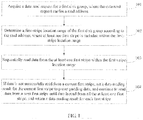
FIG. 1 is a flowchart of a data access method according toEmbodiment 1 of the present invention; -
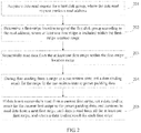
FIG. 2 is a flowchart of a data access method according toEmbodiment 2 of the present invention; -
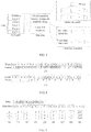
FIG. 3 is a schematic diagram of a structure of a first disk according toEmbodiment 2 of the present invention; -
FIG. 4 is a schematic diagram of divided stripes according toEmbodiment 2 of the present invention; -
FIG. 5 is a schematic diagram of a structure of a first type of first disk group according toEmbodiment 2 of the present invention; -
FIG. 6 is a schematic diagram of a structure of a second type of first disk group according toEmbodiment 2 of the present invention; -
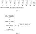
FIG. 7 is a schematic diagram of a structure of software for data access according toEmbodiment 2 of the present invention; -
FIG. 8 is a schematic diagram of a structure of a software RAID according toEmbodiment 2 of the present invention; -
FIG. 9 is a schematic diagram of a structure of hardware for data access according toEmbodiment 2 of the present invention; -
FIG. 10 is a flowchart of a data access method according toEmbodiment 3 of the present invention; -
FIG. 11 is a schematic diagram of a display interface according toEmbodiment 3 of the present invention; and -
FIG. 12 is a schematic diagram of a structure of a data access apparatus according toEmbodiment 4 of the present invention. - To access data, a device for storing the data needs to be determined. When a storage device is determined, performance, reliability, and costs of the storage device need to be considered. A redundant array of independent disks achieves a better balance among performance, reliability, and costs. Therefore, for most civil storage devices, a technology of redundant array of independent disks is used to build storage environments.
- A data access method provided in embodiments of the present invention may be applied to not only scenarios of streaming media data storage, but also scenarios in which data reliability is not strictly required, such as scenarios of text storage and Internet caching.
- To make the objectives, technical solutions, and advantages of the present invention clearer, the following further describes the embodiments of the present invention in detail with reference to the accompanying drawings.
- An embodiment of the present invention provides a data access method, which is applied to a redundant array of independent disks. The redundant array of independent disks includes at least a first disk group, the first disk group includes at least one disk, and each disk is divided in advance into at least one stripe. Referring to
FIG. 1 , a method process provided in this embodiment includes: - 101: Acquire a data read request for a first disk group, where the data read request carries a read address.
- 102: Determine a first-stripe location range of the first disk group according to the read address, where at least one first stripe is included within the first-stripe location range.
- 103: Sequentially read data from the at least one first stripe within the first-stripe location range.
- 104: If data is not successfully read from a current first stripe, set a data reading result for the current first stripe to preset padding data, and continue to read data from a next first stripe until data is read from all the at least one first stripe; and return a data reading result for each first stripe.
- Preferably, the redundant array of independent disks further includes a second disk group, and the method further includes:
- acquiring a data write request for the first disk group, where the data write request carries a write address;
- determining a second-stripe location range of the first disk group according to the write address, where at least one second stripe is included within the second-stripe location range;
- sequentially writing data into the at least one second stripe within the second-stripe location range;
- if data is not successfully written into a current second stripe, scanning to learn a state of the first disk group, where the state of the first disk group is one of a read-only state, a normal read/write state, and a degraded state; and
- if the first disk group is in the read-only state, continuing to write data into a corresponding stripe in the second disk group until all data is written.
- Preferably, after the scanning to learn a state of the first disk group, the method further includes:
- if the first disk group is in the degraded state, sending an alarm in response.
- Preferably, the method further includes:
- checking whether a state of each disk in the first disk group has changed, where the state of the disk is one of a new-disk state, a normal state, and a faulty state; and
- if a first disk in the first disk group changes from the faulty state to the new-disk state, formatting the first disk, dividing the formatted first disk into stripes, and setting a state of each stripe that is obtained by division to a not-written state.
- Preferably, after the setting a state of each stripe that is obtained by division to a not-written state, the method further includes:
- during data reading from a stripe in the not-written state, setting a data reading result for the stripe in the not-written state to preset padding data.
- Preferably, the method further includes:
- checking whether the first disk group is currently in a read-only state, where the read-only state indicates that at least two disks in the first disk group are in a faulty state;
- if the first disk group is currently in a non-read-only state, determining whether a last detected state of the first disk group is the read-only state; and
- if the last detected state of the first disk group is the read-only state, setting the state of the first disk group to the non-read-only state, where the non-read-only state includes a degraded state and a normal read/write state.
- Preferably, after the checking whether the first disk group is currently in a read-only state, the method further includes:
- if the first disk group is currently in the read-only state, determining whether the last detected state of the first disk group is the non-read-only state; and
- if the last detected state of the first disk group is the non-read-only state, setting the state of the first disk group to the read-only state.
- In the method provided in this embodiment, data is sequentially read within a first-stripe location range of a first disk group, where the first-stripe location range is determined according to a read address that is carried in an acquired data read request for the first disk group, a data reading result for a first stripe whose data is not successfully read is set to preset padding data, data reading proceeds to a next first stripe until data is read from all first stripes, and a data reading result for each first stripe is returned, which reduces data loss and shortens access interruption time when data is not successfully read, and ensures data confidentiality because no third party is involved.
- An embodiment of the present invention provides a data access method, which is applied to a redundant array of independent disks. The redundant array of independent disks includes at least a first disk group, the first disk group includes at least one disk, and each disk is divided in advance into at least one stripe. With reference to the content of the foregoing
Embodiment 1, the method provided in this embodiment of the present invention is explained and described in detail. Referring toFIG. 2 , a method process includes: - 201: Acquire a data read request for a first disk group, where the data read request carries a read address.
- A manner of acquiring the data read request is not specifically limited in this embodiment. In specific implementation, a manner of receiving a message may be used to acquire the data read request. Certainly, in addition to the foregoing manner, another manner may also be used.
- Further, to determine a read range, the data read request carries the read address, according to which the read range is determined. In addition to carrying the read address, the data read request may further carry other information, which is not specifically limited in this embodiment. For example, the data read request carries a read sequence.
- 202: Determine a first-stripe location range of the first disk group according to the read address, where at least one first stripe is included within the first-stripe location range.
- Specifically, the determining a first-stripe location range of the first disk group according to the read address includes but is not limited to: computing, according to the read address, first disks in the first disk group that are corresponding to the read address, and computing a first-stripe location range of each first disk, where the first-stripe location range of the first disk group is a collection of the first-stripe location ranges of the first disks. Certainly, in addition to the foregoing manner, another manner may be used to determine the first-stripe location range of the first disk group according to the read address, which is not specifically limited in this embodiment.
- It should be noted that at least one first stripe is included within the first-stripe location range, and data may be sequentially read from the at least one first stripe within the first-stripe location range in a subsequent step.
- For ease of understanding, a descriptive example assumes that the first disk group includes disks D1 to D8. A read address is
stripe 1 on D1 tostripe 1 on D4, wherestripe 1 on D1 isstripe 1 on the disk D1 andstripe 1 of D4 isstripe 1 on the disk D4. Computed according to the read address, first disks in the first disk group that are corresponding to the read address are D1 to D4. It is computed that a first-stripe location range of the disk D1 isstripe 1, that a first-stripe location range of the disk D2 isstripe 1, that a first-stripe location range of the disk D3 isstripe 1, and that a first-stripe location range of the disk D4 isstripe 1. Therefore, the first-stripe location range of the first disk group includesstripe 1 on the disk D1,stripe 1 on the disk D2,stripe 1 on the disk D3, andstripe 1 on the disk D4. That is, four first stripes are included within the first-stripe location range. - 203: Sequentially read data from the at least one first stripe within the first-stripe location range.
- The first-stripe location range of the first disk group has been determined according to the read address, and therefore, data may be sequentially read from the at least one first stripe within the first-stripe location range directly. A manner of reading data from a stripe is not specifically limited in this embodiment. For example, if data to be accessed is consecutive data, data that is not requested may be read in advance, and the read data is stored in a memory. After a data read request is acquired, the data is directly read from the memory, thereby increasing a speed of data reading. For another example, if data to be accessed is random data, the data is directly read from a corresponding storage area after a data read request is acquired.
- 204: During data reading from a stripe in a not-written state, set a data reading result for the stripe in the not-written state to preset padding data.
- To be able to determine a state of a stripe, the method provided in this embodiment further includes: checking whether a state of each disk in the first disk group has changed, where the state of the disk is one of a new-disk state, a normal state, and a faulty state; if a first disk in the first disk group changes from the faulty state to the new-disk state, formatting the first disk, dividing the formatted first disk into stripes, and setting a state of each stripe that is obtained by division to a not-written state.
- A manner of triggering a check on the state of each disk in the first disk group is not specifically limited in this embodiment. In specific implementation, a check on a state of a disk may be triggered regularly. Certainly, in addition to the foregoing manner, another manner may also be used to trigger a check on the state of the disk. The state of the disk is one of the new-disk state, the normal state, and the faulty state. A disk in the new-disk state is a disk that is newly inserted into a disk group, a disk in the normal state is a disk from which data can be read and into which data can be written in the disk group, and a disk in the faulty state is a disk that is faulty or is removed from the disk group.
- If the first disk in the first group changes from the faulty state to the new-disk state, the first disk may have been manually replaced with a new disk. To normally use the new first disk, the new first disk is formatted, the formatted first disk is divided into stripes, and a state of each stripe that is obtained by division is set to the not-written state. States of a stripe are not specifically limited in this embodiment, and the states of a stripe include but are not limited to a written state and the not-written state. It should be noted that, after the first disk is formatted, and the formatted first disk is divided into stripes, data may be normally read from and written into the first disk, and the first disk changes from the new-disk state to the normal state.
- For ease of understanding, a first disk shown in
FIG. 3 is used as an example for description. The first disk is divided into two areas for storing data, which are respectively a data area and a metadata area. The data area is divided intostripe 1 tostripe 5, and states ofstripe 1 tostripe 5 are all set to the not-written state because the first disk has changed from the faulty state to the new-disk state. The metadata area is further divided into a global metadata area and a local disk metadata area. In the global metadata area, metadata of a first disk group is stored in a form of a B+ tree. In the local disk metadata area, according to the metadata of the first disk group that is stored in the global metadata area, an identifier of a stripe in the not-written state on the first disk is stored in an "idle stripe linked list", and an identifier of a stripe in the written state on the first disk is stored in a "used stripe linked list". The metadata of the first disk group is stored in a global metadata area of each first disk in the first disk group in a mirroring manner, that is, the same metadata of the first disk group is recorded in the global metadata area of each first disk in the first disk group. - In addition, a size of a divided stripe is not specifically limited in this embodiment. In specific implementation, different division may be performed according to different data. Using streaming media data as an example, especially for a high-definition video, when data in one or two stripes is lost, only several picture frames may be damaged. With a playback rate of 25 frames per second, the several picture frames that are damaged do not have a significant visual impact. A great majority of decoders and players can tolerate such an error. As data in damaged stripes increases, the playback of the video may become intermittent. In a scenario of video surveillance, such video data is generally of great importance.
- For ease of understanding, stripes obtained by division and shown in
FIG. 4(1) are used as an example for description. The first row is the stripes obtained by division, a stripe size is 1 MB, data a, b, c, e, f, h, i, j, k, m, n, p, q, r, s, u, v, and x in the stripes is not lost, and data in stripes marked with 0 is lost. The second row is video data types, where I represents a key frame (I-frame), P represents a forward-predicted frame (P-frame), and I-frames and P-frames corresponding to 0-data stripes are damaged frames. When data is read subsequently, data is successfully read from stripes corresponding to the first I-frame and the first to the third P-frames, and can be rendered to a screen; data is not successfully read from stripes corresponding to the fourth P-frame and the fifth P-frame, and if a decoder obtains garbled data, artifacts are displayed on the screen for a short time. For a display effect of subsequent frames, reference may be made to the foregoing content. For video data with an 8 Mbps bit rate, the video is mostly played smoothly with occasional frame freezing and few artifacts. - For another example, stripes obtained by division and shown in
FIG. 4(2) are used as an example for description. The first row is the stripes obtained by division, and a stripe size is 256 KB. The second row is video data types, where a bit rate is the same as that inFIG. 4(1) . As can be seen fromFIG. 4(2) , when a quantity of stripes that are corresponding to a frame increases, a quantity of damaged stripes also increases. Therefore, a proper stripe size is related to a bit rate of media data. A larger stripe size can reduce a probability that I-frames are continuously damaged, but a quantity of frames included in one stripe also increases, and more frames are skipped when the media data is played. A smaller stripe size increases the probability that I-frames are continuously damaged, which results in poor effect of media data playback. For a 1080p video at an 8 Mbps bit rate, a stripe size of 1 MB is a better choice. For a video file at another bit rate, a stripe size may be discretionarily reduced according to the foregoing proportion of a bit rate to a stripe size. - Further, during data reading from a stripe in the not-written state, a data reading result for the stripe in the not-written state is set to preset padding data. Because no data is stored in the stripe in the not-written state, during data reading from the stripe in the not-written state, data is not actually read, but the data reading result for the stripe in the not-written state is set to the preset padding data. A numeric value of the preset padding data is not specifically limited in this embodiment. In specific implementation, the numeric value of the preset padding data may be zero. Certainly, in addition to the foregoing numeric value, another value may be preset.
- 205: If data is not successfully read from a current first stripe, set a data reading result for the current first stripe to the preset padding data, and continue to read data from a next first stripe until data is read from all the at least one first stripe; and return a data reading result for each first stripe.
- To ensure that data can further be read from another first disk in the disk group when more than one first disk in the first disk group is in the faulty state, in the method provided in this embodiment, when data is not successfully read from a current first stripe, a data reading result for the current first stripe is set to the preset padding data, and data reading proceeds to a next first stripe. For the preset padding data, reference may be made to the content of the foregoing
step 204, and details are not described herein again. After data is read from all the at least one first stripe within the first-stripe location range, a data reading result for each first stripe is returned, thereby avoiding a case that data cannot be read from any first disk in the first group when the first disk group fails. - It should be noted that in RAID5, if one disk is in the faulty state, data on the disk may be restored according to redundancy data in a disk group. For ease of understanding, a first disk group shown in
FIG. 5 is used as an example. The first disk group includes nine disks, D1 to D9. Data abcdefghijklmnopqrstuvwx is segmented into data blocks a, b, c, d, e, f, g, h, i, j, k, l, m, n, o, p, q, r, s, t, u, v, w, and x, which are respectively stored in stripes of the disks D1 to D9. Data a, i, and q are respectively stored in three stripes of the disk D1; data b, j, and r are respectively stored in three stripes of the disk D2; data c, k, and s are respectively stored in three stripes of the disk D3; data d, 1, and t are respectively stored in three stripes of the disk D4; data e, m, and u are respectively stored in three stripes of the disk D5; data f, n, and v are respectively stored in three stripes of the disk D6; data g, o, and w are respectively stored in three stripes of the disk D7; and data h, p, and x are respectively stored in three stripes of the disk D8. Redundancy data xor1, xor2, and xor3 are respectively stored in three stripes of the disk D9. xor1 = a^b^c^d^e^f^g^h, xor2 = i^j^k^1^m^n^o^p, and xor3 = q^r^s^t^u^v^w^x, where ^ represents exclusive OR. When any one disk of D1 to D8 is in the faulty state, data in the any one disk may be restored by means of redundancy calculation. - For example, when the disk D3 is in the faulty state, a redundancy calculation process for data c is:

- For redundancy calculation processes for data k and data s, reference may be made to the redundancy calculation process for data c, and details are not described herein again.
- For another example, the disks D4 and D7 are in the faulty state. As shown in
FIG. 6 , data on the disks D4 and D7 cannot be obtained by means of redundancy calculation, and therefore, the data cannot be successfully read from the disks D4 and D7. The preset padding data is set to 0, and data reading results for the disks D4 and D7 are both 0s. If the first-stripe location range of the first disk group that is determined according to the read address is all stripes of D1 to D8, a returned data reading result is abc0ef0hijk0mn0pqrs0uv0x. - Further, the data access method provided in this embodiment of the present invention may be implemented by means of software, or be implemented by means of hardware. For ease of understanding, a structure of software for data access shown in
FIG. 7 is used as an example for description. Software RAID is located between a VFS (Virtual File System, virtual file system) and an XFS (X-File System, X-file system), and a WebUI (User Interface, user interface) and a CLI (Command Line Interface, command line interface) are provided for controlling the software RAID, where a RAID user can control the software RAID by using the VFS. A structure of the software RAID may be shown inFIG. 8(1) , or may be shown inFIG. 8(2) . Compared with the software RAID inFIG. 8(1) , the software RAID inFIG. 8(2) is not provided with a RAID file system and a read/write cache, and a virtual block device is directly connected to a standard file system. When a disk group meets a failure condition, lost data may be key data in a standard file, which results in damage to the standard file system; therefore, the software RAID is generally not applied to a file system. - In addition, in a structure of hardware for data access shown in
FIG. 9 , a RAID card can be used to implement the data access method provided in this embodiment of the present invention. The RAID card is located between an operating system and a disk. - In the method provided in this embodiment, data is sequentially read within a first-stripe location range of a first disk group, where the first-stripe location range is determined according to an acquired read address that is carried in a data read request for the first disk group, a data reading result for a first stripe whose data is not successfully read is set to preset padding data, data reading proceeds to a next first stripe until data is read from all first stripes, and a data reading result for each first stripe is returned, which reduces data loss and shortens access interruption time when data is not successfully read, and ensures data confidentiality because no third party is involved.
- An embodiment of the present invention provides a data access method, which is applied to a redundant array of independent disks. The redundant array of independent disks includes a first disk group and a second disk group, both the first disk group and the second disk group include at least one disk, and each disk is divided in advance into at least one stripe. Referring to
FIG. 10 , a method process includes: - 1001: Acquire a data write request for a first disk group, where the data write request carries a write address.
- The data write request for the first disk group is acquired for accessing data in the disk group. A manner of acquiring the data write request is not specifically limited in this embodiment. In specific implementation, a manner of receiving a message may be used to acquire the data write request. Certainly, in addition to the foregoing manner, another manner may also be used.
- Further, to determine a write range, the data write request carries the write address, according to which the write range is determined. In addition to carrying the write address, the data write request may further carry other information, which is not specifically limited in this embodiment. For example, the data write request carries a write sequence.
- 1002: Determine a second-stripe location range of the first disk group according to the write address, where at least one second stripe is included within the second-stripe location range.
- Specifically, the determining a second-stripe location range of the first disk group according to the write address includes but is not limited to: computing, according to the write address, first disks in the first disk group that are corresponding to the write address, and computing a second-stripe location range of each first disk, where the second-stripe location range of the first disk group is a collection of the second-stripe location ranges of the first disks. Certainly, in addition to the foregoing manner, another manner may be used to determine the second-stripe location range of the first disk group according to the write address, which is not specifically limited in this embodiment.
- It should be noted that at least one first stripe is included within the first-stripe location range, and data may be sequentially written into the at least one second stripe within the second-stripe location range in a subsequent step.
- For ease of understanding, a descriptive example assumes that the first disk group includes disks D1 to D8. A write address is
stripe 1 on D1 tostripe 1 on D4, wherestripe 1 on D1 isstripe 1 on the disk D1 andstripe 1 of D4 isstripe 1 on the disk D4. Computed according to the write address, first disks in the first disk group that are corresponding to the write address are D1 to D4. It is computed that a second-stripe location range of the disk D1 isstripe 1, that a second-stripe location range of the disk D2 isstripe 1, that a second-stripe location range of the disk D3 isstripe 1, and that a second-stripe location range of the disk D4 isstripe 1. Therefore, the second-stripe location range of the first disk group includesstripe 1 on the disk D1,stripe 1 on the disk D2,stripe 1 on the disk D3, andstripe 1 on the disk D4, that is, four second stripes are included within the second-stripe location range. - 1003: Sequentially write data into the at least one second stripe within the second-stripe location range.
- The second-stripe location range of the first disk group has been determined according to the write address, and therefore, data may be sequentially written into the at least one second stripe within the second-stripe location range directly. A manner of writing data into a stripe is not specifically limited in this embodiment. In specific implementation, to-be-written data may be segmented into multiple data blocks, and the data is written in parallel into the at least one second stripe within the second-stripe location range, thereby increasing a speed of data writing. Certainly, in addition to the foregoing manner, another manner may also be used.
- 1004: If data is not successfully written into a current second stripe, scan to learn a state of the first disk group, where the state of the first disk group is one of a read-only state, a normal read/write state, and a degraded state.
- To successfully write data into the redundant array of independent disks, in the method provided in this embodiment, scanning is performed to learn the state of the first disk group when the data is not successfully written into the current second stripe. It should be noted that, in addition to a case in which data is not successfully written into a current second stripe, scanning to learn the state of the first disk group may also be triggered regularly. The state of the first disk group is one of the read-only state, the normal read/write state, and the degraded state. In the read-only state, only a data read operation is allowed and a data write operation is not allowed for all first disks in the first disk group. In the normal read/write state, both the data read operation and the data write operation are allowed for all the first disks in the first disk group. In the degraded state, both the data read operation and the data write operation are allowed for all the first disks in the first disk group, and at least one first disk is in a faulty state. The degraded state is between the read-only state and the normal read/write state. For different redundant arrays of independent disks, states of the first disk group are corresponding to different states of first disks.
- For ease of understanding, RAID5 is used as an example for description. If more than one first disk in the first disk group is in the faulty state, the state, learned by scanning, of the first disk group is the read-only state. If no first disk in the first disk group is in the faulty state, the state, learned by scanning, of the first disk group is the normal read/write state. If one first disk in the first disk group is in the faulty state, the state, learned by scanning, of the first disk group is the degraded state.
- 1005: If the first disk group is in the read-only state, continue to write data into a corresponding stripe in a second disk group until all data is written.
- If the first disk group is in the read-only state, data can only be read from the first disk group, but cannot be written into a stripe of the first disk group. To be able to continue writing data into the redundant array of independent disks, data writing proceeds to the corresponding stripe in the second disk group until all data is written.
- Preferably, to restore the normal read/write state of the first disk group, the method provided in this embodiment further includes but is not limited to: displaying a first disk that is in the faulty state in the first disk group. A manner of displaying the first disk is not specifically limited in this embodiment. For ease of understanding, a display interface shown in
FIG. 11 is used as an example for description. Identifiers corresponding to all the first disks in the first disk group are displayed according to slot locations actually corresponding to the first disks and are D1 to D8 respectively. Locations of the disk D4 and the disk D7 are marked, which indicates that the disk D4 and the disk D7 are in the faulty state. - A location of a first disk that is in the faulty state has been marked, which facilitates manual replacement of the first disk. To check whether a first disk has been replaced, the method provided in this embodiment includes but is not limited to: checking whether a state of each disk in the first disk group has changed, where the state of the disk is one of a new-disk state, a normal state, and a faulty state; and if a first disk in the first disk group changes from the faulty state to the new-disk state, formatting the first disk, dividing the formatted first disk into stripes, and setting a state of each stripe that is obtained by division to a not-written state.
- Further, after the checking whether a state of each disk in the first disk group has changed, the method provided in this embodiment further includes but is not limited to:
- (1) Checking whether the first disk group is currently in a read-only state, where the read-only state indicates that at least two disks in the first disk group are in the faulty state; if the first disk group is currently in a non-read-only state, executing (2); and if the first disk group is currently in the read-only state, executing (4);
- (2) Determining whether a last detected state of the first disk group is the read-only state;
- (3) If the last detected state of the first disk group is the read-only state, setting the state of the first disk group to the non-read-only state, where the non-read-only state includes a degraded state and a normal read/write state.
- (4) Determining whether a last detected state of the first disk group is the non-read-only state;
- (5) If the last detected state of the first disk group is the non-read-only state, setting the state of the first disk group to the read-only state.
- In addition, to avoid a failure condition of the disk group as much as possible, after the state of the first disk group is learned by scanning, if the state of the first disk group is the degraded state, an alarm is sent in response. When the state of the first disk group is the degraded state, it indicates that one first disk in the first disk group is in the faulty state. The alarm sent in response can be a reminder of manual disk replacement. A manner of sending an alarm in response is not specifically limited in this embodiment. In specific implementation, a manner of sending alarm information may be used to send an alarm in response. In addition, location information of a disk may further be carried in the alarm information to facilitate disk replacement.
- It should be noted that the data access method provided in this embodiment of the present invention may be implemented by means of software, or be implemented by means of hardware. For details, reference may be made to the specific description and content of software implementation and hardware implementation in the foregoing
Embodiment 2, and details are not described herein again. - In the method provided in this embodiment of the present invention, when data is not successfully written into a current second stripe, it is learned by scanning that a first disk group is in a read-only state, and data writing proceeds to a corresponding stripe of a second disk group until all data is written, thereby implementing data writing without rebuilding a disk group, which shortens access interruption time and ensures data confidentiality because no third party is involved.
- Referring to
FIG. 12 , an embodiment of the present invention provides a data access apparatus. The apparatus is applied to a redundant array of independent disks, where the redundant array of independent disks includes at least a first disk group, the first disk group includes at least one disk, and each disk is divided in advance into at least one stripe. The apparatus includes: - a first acquiring
module 1201, configured to acquire a data read request for the first disk group, where the data read request carries a read address; - a first determining
module 1202, configured to determine a first-stripe location range of the first disk group according to the read address, where at least one first stripe is included within the first-stripe location range; - a
reading module 1203, configured to sequentially read data from the at least one first stripe within the first-stripe location range; - a
first setting module 1204, configured to: when data is not successfully read from a current first stripe, set a data reading result for the current first stripe to preset padding data, and continue to read data from a next first stripe until data is read from all the at least one first stripe; and - a returning
module 1205, configured to return a data reading result for each first stripe. - Preferably, the redundant array of independent disks further includes a second disk group, and the apparatus further includes:
- a second acquiring module, configured to acquire a data write request for the first disk group, where the data write request carries a write address;
- a second determining module, configured to determine a second-stripe location range of the first disk group according to the write address, where at least one second stripe is included within the second-stripe location range;
- a first writing module, configured to sequentially write data into the at least one second stripe within the second-stripe location range;
- a scanning module, configured to: when data is not successfully written into a current second stripe, scan to learn a state of the first disk group, where the state of the first disk group is one of a read-only state, a normal read/write state, and a degraded state; and
- a second writing module, configured to: when the first disk group is in the read-only state, continue to write data into a corresponding stripe in the second disk group until all data is written.
- Preferably, the apparatus further includes:
- a responding module, configured to: when the first disk group is in the degraded state, send an alarm in response.
- Preferably, the apparatus further includes:
- a first checking module, configured to check whether a state of each disk in the first disk group has changed, where the state of the disk is one of a new-disk state, a normal state, and a faulty state; and
- a formatting module, configured to: when a first disk in the first disk group changes from the faulty state to the new-disk state, format the first disk;
- a dividing module, configured to divide the formatted first disk into stripes; and
- a second setting module, configured to set a state of each stripe that is obtained by division to a not-written state.
- Preferably, the
first setting module 1204 is further configured to: during data reading from a stripe in the not-written state, set a data reading result for the stripe in the not-written state to preset padding data. - Preferably, the apparatus further includes:
- a second checking module, configured to check whether the first disk group is currently in a read-only state, where the read-only state indicates that at least two disks in the first disk group are in a faulty state;
- a third determining module, configured to: when the first disk group is currently in a non-read-only state, determine whether a last detected state of the first disk group is the read-only state; and
- a third setting module, configured to: when the last detected state of the first disk group is the read-only state, set the state of the first disk group to the non-read-only state, where the non-read-only state includes a degraded state and a normal read/write state.
- Preferably, the apparatus further includes:
- a fourth determining module, configured to: when the first disk group is currently in the read-only state, determine whether the last detected state of the first disk group is the non-read-only state; and
- a fourth setting module, configured to: when the last detected state of the first disk group is the non-read-only state, set the state of the first disk group to the read-only state.
- According to the apparatus provided in this embodiment, data is sequentially read within a first-stripe location range of a first disk group, where the first-stripe location range is determined according to an acquired read address that is carried in a data read request for the first disk group, a data reading result for a first stripe whose data is not successfully read is set to preset padding data, data reading proceeds to a next first stripe until data is read from all first stripes, and a data reading result for each first stripe is returned, which reduces data loss and shortens access interruption time when data is not successfully read, and ensures data confidentiality because no third party is involved.
- An embodiment of the present invention provides a data access terminal. The terminal is applied to a redundant array of independent disks, where the redundant array of independent disks includes at least a first disk group, the first disk group includes at least one disk, and each disk is divided in advance into at least one stripe. The terminal includes a processor, a transmitter, and a receiver.
- The receiver is configured to acquire a data read request for the first disk group, where the data read request carries a read address.
- The processor is configured to determine a first-stripe location range of the first disk group according to the read address, where at least one first stripe is included within the first-stripe location range.
- The processor is further configured to sequentially read data from the at least one first stripe within the first-stripe location range.
- The processor is further configured to: when data is not successfully read from a current first stripe, set a data reading result for the current first stripe to preset padding data, and continue to read data from a next first stripe until data is read from all the at least one first stripe.
- The transmitter is configured to return a data reading result for each first stripe.
- In an optional embodiment, the processor is further configured to check whether a state of each disk in the first disk group has changed, where the state of the disk is one of a new-disk state, a normal state, and a faulty state.
- The processor is further configured to: when a first disk in the first disk group changes from the faulty state to the new-disk state, format the first disk, divide the formatted first disk into stripes, and set a state of each stripe that is obtained by division to a not-written state.
- In an optional embodiment, the processor is further configured to: during data reading from a stripe in the not-written state, set a data reading result for the stripe in the not-written state to preset padding data.
- In an optional embodiment, the processor is further configured to check whether the first disk group is currently in a read-only state, where the read-only state indicates that at least two disks in the first disk group are in a faulty state.
- The processor is further configured to: when the first disk group is currently in a non-read-only state, determine whether a last detected state of the first disk group is the read-only state.
- The processor is further configured to: when the last detected state of the first disk group is the read-only state, set the state of the first disk group to the non-read-only state, where the non-read-only state includes a degraded state and a normal read/write state.
- In an optional embodiment, the processor is further configured to: when the first disk group is currently in the read-only state, determine whether a last detected state of the first disk group is the non-read-only state.
- The processor is further configured to: when the last detected state of the first disk group is the non-read-only state, set the state of the first disk group to the read-only state.
- According to the terminal provided in this embodiment, data is sequentially read within a first-stripe location range of a first disk group, where the first-stripe location range is determined according to an acquired read address that is carried in a data read request for the first disk group, a data reading result for a first stripe whose data is not successfully read is set to preset padding data, data reading proceeds to a next first stripe until data is read from all first stripes, and a data reading result for each first stripe is returned, which reduces data loss and shortens access interruption time when data is not successfully read, and ensures data confidentiality because no third party is involved.
- An embodiment of the present invention provides a data access terminal. The terminal is applied to a redundant array of independent disks, where the redundant array of independent disks includes at least a first disk group, the first disk group includes at least one disk, and each disk is divided in advance into at least one stripe. The terminal includes a processor and a receiver.
- The receiver is configured to acquire a data write request for the first disk group, where the data write request carries a write address.
- The processor is configured to determine a second-stripe location range of the first disk group according to the write address, where at least one second stripe is included within the second-stripe location range.
- The processor is further configured to sequentially write data into the at least one second stripe within the second-stripe location range.
- The processor is further configured to: when data is not successfully written into a current second stripe, scan to learn a state of the first disk group, where the state of the first disk group is one of a read-only state, a normal read/write state, and a degraded state.
- The processor is further configured to: when the first disk group is in the read-only state, continue to write data into a corresponding stripe in the second disk group until all data is written.
- In an optional embodiment, the processor is further configured to: when the first disk group is in the degraded state, send an alarm in response.
- In an optional embodiment, the processor is further configured to check whether a state of each disk in the first disk group has changed, where the state of the disk is one of a new-disk state, a normal state, and a faulty state.
- The processor is further configured to: when a first disk in the first disk group changes from the faulty state to the new-disk state, format the first disk, divide the formatted first disk into stripes, and set a state of each stripe that is obtained by division to a not-written state.
- In an optional embodiment, the processor is further configured to check whether the first disk group is currently in a read-only state, where the read-only state indicates that at least two disks in the first disk group are in a faulty state.
- The processor is further configured to: when the first disk group is currently in a non-read-only state, determine whether a last detected state of the first disk group is the read-only state.
- The processor is further configured to: when the last detected state of the first disk group is the read-only state, set the state of the first disk group to the non-read-only state, where the non-read-only state includes a degraded state and a normal read/write state.
- In an optional embodiment, the processor is further configured to: when the first disk group is currently in the read-only state, determine whether a last detected state of the first disk group is the non-read-only state.
- The processor is further configured to: when the last detected state of the first disk group is the non-read-only state, set the state of the first disk group to the read-only state.
- According to the terminal provided in this embodiment of the present invention, when data is not successfully written into a current second stripe, it is learned by scanning that a first disk group is in a read-only state, and data writing proceeds to a corresponding stripe of a second disk group until all data is written, thereby implementing data writing without rebuilding a disk group, which shortens access interruption time and ensures data confidentiality because no third party is involved.
- It should be noted that, when the data access apparatus provided by the foregoing embodiments is used for data access, the division of the foregoing functional modules is merely used as an example. In actual application, the foregoing functions can be allocated to different functional modules and implemented according to a requirement, that is, an inner structure of the apparatus is divided into different functional modules to implement all or some of the functions described above. In addition, the data access apparatus provided in the foregoing embodiment belongs to a same idea as the embodiments of the data access method. For a specific implementation process thereof, reference is made to the method embodiments, and details are not described herein again.
- The sequence numbers of the foregoing embodiments of the present invention are merely for illustrative purposes, and are not intended to indicate priorities of the embodiments.
- A person of ordinary skill in the art may understand that all or some of the steps of the embodiments may be implemented by hardware or a program instructing related hardware. The program may be stored in a computer-readable storage medium. The storage medium may be a read-only memory, a magnetic disk, an optical disc, or the like.
- The foregoing descriptions are merely exemplary embodiments of the present invention, but are not intended to limit the present invention. Any modification, equivalent replacement, and improvement made without departing from the principle of the present invention shall fall within the protection scope of the present invention.
Claims (12)
- A data access method, wherein the method is applied to a redundant array of independent disks, the redundant array of independent disks comprises at least a first disk group, the first disk group comprises at least one disk, each disk is divided in advance into at least one stripe, and the method comprises:acquiring (101, 201) a data read request for the first disk group, wherein the data read request carries a read address;determining (102, 202) a first-stripe location range of the first disk group according to the read address, wherein at least one first stripe is comprised within the first-stripe location range;sequentially reading (103, 203) data from the at least one first stripe within the first-stripe location range; andif data is not successfully read from a current first stripe, setting (104, 205) a data reading result for the current first stripe to preset padding data, and continuing to read data from a next first stripe until data is read from all the at least one first stripe; and returning a data reading result for each first stripe;characterized in thatthe redundant array of independent disks further comprises a second disk group, and the method further comprises:acquiring (1001) a data write request for the first disk group, wherein the data write request carries a write address;determining (1002) a second-stripe location range of the first disk group according to the write address, wherein at least one second stripe is comprised within the second-stripe location range;sequentially writing (1003) data into the at least one second stripe within the second-stripe location range;if data is not successfully written into a current second stripe, scanning (1004) to learn a state of the first disk group, wherein the state of the first disk group is one of a read-only state, a normal read/write state, and a degraded state; andif the first disk group is in the read-only state, continuing (1005) to write data into a corresponding stripe in the second disk group until all data is written.
- The method according to claim 1, after the scanning to learn a state of the first disk group, further comprising:if the first disk group is in the degraded state, sending an alarm in response.
- The method according to claim 1 or 2, wherein the method further comprises:checking whether a state of each disk in the first disk group has changed, wherein the state of the disk is one of a new-disk state, a normal state, and a faulty state; andif a first disk in the first disk group changes from the faulty state to the new-disk state, formatting the first disk, dividing the formatted first disk into stripes, and setting a state of each stripe that is obtained by division to a not-written state.
- The method according to claim 3, after the setting a state of each stripe that is obtained by division to a not-written state, further comprising:during data reading from a stripe in the not-written state, setting (204) a data reading result for the stripe in the not-written state to preset padding data.
- The method according to any one of claims 1 to 4, wherein the method further comprises:checking whether the first disk group is currently in a read-only state, wherein the read-only state indicates that at least two disks in the first disk group are in a faulty state;if the first disk group is currently in a non-read-only state, determining whether a last detected state of the first disk group is the read-only state; andif the last detected state of the first disk group is the read-only state, setting the state of the first disk group to the non-read-only state, wherein the non-read-only state comprises a degraded state and a normal read/write state.
- The method according to claim 5, after the checking whether the first disk group is currently in a read-only state, further comprising:if the first disk group is currently in the read-only state, determining whether the last detected state of the first disk group is the non-read-only state; andif the last detected state of the first disk group is the non-read-only state, setting the state of the first disk group to the read-only state.
- A data access apparatus, wherein the apparatus is applied to a redundant array of independent disks, the redundant array of independent disks comprises at least a first disk group, the first disk group comprises at least one disk, each disk is divided in advance into at least one stripe, and the apparatus comprises:a first acquiring module (1201), configured to acquire a data read request for the first disk group, wherein the data read request carries a read address;a first determining module (1202), configured to determine a first-stripe location range of the first disk group according to the read address, wherein at least one first stripe is comprised within the first-stripe location range;a reading module (1203), configured to sequentially read data from the at least one first stripe within the first-stripe location range;a first setting module (1204), configured to: when data is not successfully read from a current first stripe, set a data reading result for the current first stripe to preset padding data, and continue to read data from a next first stripe until data is read from all the at least one first stripe; anda returning module (1205), configured to return a data reading result for each first stripe;characterized in thatthe redundant array of independent disks further comprises a second disk group, and the apparatus further comprises:a second acquiring module, configured to acquire a data write request for the first disk group, wherein the data write request carries a write address;a second determining module, configured to determine a second-stripe location range of the first disk group according to the write address, wherein at least one second stripe is comprised within the second-stripe location range;a first writing module, configured to sequentially write data into the at least one second stripe within the second-stripe location range;a scanning module, configured to: when data is not successfully written into a current second stripe, scan to learn a state of the first disk group, wherein the state of the first disk group is one of a read-only state, a normal read/write state, and a degraded state; anda second writing module, configured to: when the first disk group is in the read-only state, continue to write data into a corresponding stripe in the second disk group until all data is written.
- The apparatus according to claim 7, wherein the apparatus further comprises:a responding module, configured to: when the first disk group is in the degraded state, send an alarm in response.
- The apparatus according to any one of claims 7 to 8, wherein the apparatus further comprises:a first checking module, configured to check whether a state of each disk in the first disk group has changed, wherein the state of the disk is one of a new-disk state, a normal state, and a faulty state; anda formatting module, configured to: when a first disk in the first disk group changes from the faulty state to the new-disk state, format the first disk;a dividing module, configured to divide the formatted first disk into stripes; anda second setting module, configured to set a state of each stripe that is obtained by division to a not-written state.
- The apparatus according to claim 9, wherein the first setting module is further configured to: during data reading from a stripe in the not-written state, set a data reading result for the stripe in the not-written state to preset padding data.
- The apparatus according to any one of claims 7 to 10, wherein the apparatus further comprises:a second checking module, configured to check whether the first disk group is currently in a read-only state, wherein the read-only state indicates that at least two disks in the first disk group are in a faulty state;a third determining module, configured to: when the first disk group is currently in a non-read-only state, determine whether a last detected state of the first disk group is the read-only state; anda third setting module, configured to: when the last detected state of the first disk group is the read-only state, set the state of the first disk group to the non-read-only state, wherein the non-read-only state comprises a degraded state and a normal read/write state.
- The apparatus according to claim 11, wherein the apparatus further comprises:a fourth determining module, configured to: when the first disk group is currently in the read-only state, determine whether the last detected state of the first disk group is the non-read-only state; anda fourth setting module, configured to: when the last detected state of the first disk group is the non-read-only state, set the state of the first disk group to the read-only state.
Priority Applications (1)
| Application Number | Priority Date | Filing Date | Title |
|---|---|---|---|
| EP17205748.1A EP3385832A1 (en) | 2014-01-07 | 2014-12-30 | Data access method and apparatus |
Applications Claiming Priority (2)
| Application Number | Priority Date | Filing Date | Title |
|---|---|---|---|
| CN201410007103.0A CN104007936B (en) | 2014-01-07 | 2014-01-07 | Access the method and device of data |
| PCT/CN2014/095668 WO2015103933A1 (en) | 2014-01-07 | 2014-12-30 | Method and apparatus for data access |
Related Child Applications (2)
| Application Number | Title | Priority Date | Filing Date |
|---|---|---|---|
| EP17205748.1A Division-Into EP3385832A1 (en) | 2014-01-07 | 2014-12-30 | Data access method and apparatus |
| EP17205748.1A Division EP3385832A1 (en) | 2014-01-07 | 2014-12-30 | Data access method and apparatus |
Publications (3)
| Publication Number | Publication Date |
|---|---|
| EP3079054A1 EP3079054A1 (en) | 2016-10-12 |
| EP3079054A4 EP3079054A4 (en) | 2016-11-09 |
| EP3079054B1 true EP3079054B1 (en) | 2018-02-21 |
Family
ID=51368607
Family Applications (2)
| Application Number | Title | Priority Date | Filing Date |
|---|---|---|---|
| EP14878327.7A Active EP3079054B1 (en) | 2014-01-07 | 2014-12-30 | Method and apparatus for data access |
| EP17205748.1A Ceased EP3385832A1 (en) | 2014-01-07 | 2014-12-30 | Data access method and apparatus |
Family Applications After (1)
| Application Number | Title | Priority Date | Filing Date |
|---|---|---|---|
| EP17205748.1A Ceased EP3385832A1 (en) | 2014-01-07 | 2014-12-30 | Data access method and apparatus |
Country Status (8)
| Country | Link |
|---|---|
| US (1) | US10585600B2 (en) |
| EP (2) | EP3079054B1 (en) |
| JP (1) | JP6229067B2 (en) |
| KR (1) | KR101743411B1 (en) |
| CN (1) | CN104007936B (en) |
| ES (1) | ES2664795T3 (en) |
| RU (1) | RU2626091C1 (en) |
| WO (1) | WO2015103933A1 (en) |
Families Citing this family (6)
| Publication number | Priority date | Publication date | Assignee | Title |
|---|---|---|---|---|
| CN104007936B (en) | 2014-01-07 | 2017-09-29 | 华为技术有限公司 | Access the method and device of data |
| CN107783784A (en) * | 2016-08-24 | 2018-03-09 | 衡宇科技股份有限公司 | Method for transmitting command from host to device controller and system using the same |
| CN110515761B (en) * | 2018-05-22 | 2022-06-03 | 杭州海康威视数字技术股份有限公司 | Data acquisition method and device |
| CN111427508B (en) * | 2019-01-09 | 2023-07-21 | 深圳市茁壮网络股份有限公司 | File equilibrium distribution method and device |
| CN111435286B (en) * | 2019-01-14 | 2023-12-05 | 深圳市茁壮网络股份有限公司 | Data storage method, device and system |
| CN115904255B (en) * | 2023-01-19 | 2023-05-16 | 苏州浪潮智能科技有限公司 | Data request method, device, equipment and storage medium |
Family Cites Families (23)
| Publication number | Priority date | Publication date | Assignee | Title |
|---|---|---|---|---|
| US5913927A (en) * | 1995-12-15 | 1999-06-22 | Mylex Corporation | Method and apparatus for management of faulty data in a raid system |
| JPH11232048A (en) * | 1998-02-19 | 1999-08-27 | Sony Corp | Data processing device and data processing method |
| US7062704B2 (en) * | 2001-04-30 | 2006-06-13 | Sun Microsystems, Inc. | Storage array employing scrubbing operations using multiple levels of checksums |
| RU2305330C2 (en) * | 2002-04-01 | 2007-08-27 | Сони Корпорейшн | Record carrier and method for recording a record carrier |
| AU2003201837A1 (en) | 2002-04-01 | 2003-10-23 | Sony Corporation | Storage medium and storage medium recording method |
| RU2303822C2 (en) * | 2002-04-01 | 2007-07-27 | Сони Корпорейшн | Method for recording data on a data carrier |
| US6944791B2 (en) * | 2002-07-18 | 2005-09-13 | Lsi Logic Corporation | Method of handling unreadable blocks during write of a RAID device |
| JP4426262B2 (en) | 2003-11-26 | 2010-03-03 | 株式会社日立製作所 | Disk array device and failure avoiding method for disk array device |
| US7188212B2 (en) * | 2004-05-06 | 2007-03-06 | International Business Machines Corporation | Method and system for storing data in an array of storage devices with additional and autonomic protection |
| TWI346944B (en) * | 2007-12-31 | 2011-08-11 | Qnap Systems Inc | Method of raid level migration and system for the same |
| US8049980B1 (en) * | 2008-04-18 | 2011-11-01 | Network Appliance, Inc. | Partial disk failures and improved storage resiliency |
| KR20100004792A (en) * | 2008-07-04 | 2010-01-13 | 삼성전자주식회사 | Method for storing defected information, information processing apparatus capable of storing defected information, information storing apparatus for transmitting defected information in storable form, and medium capable of being read by information processing apparatus, in which a software needed for storing defected information is recorded |
| US20100125695A1 (en) * | 2008-11-15 | 2010-05-20 | Nanostar Corporation | Non-volatile memory storage system |
| US7904749B2 (en) * | 2008-10-24 | 2011-03-08 | Hitachi, Ltd. | Fast data recovery from HDD failure |
| CN102023809B (en) * | 2009-09-21 | 2012-10-17 | 成都市华为赛门铁克科技有限公司 | Storage system, method for reading data from storage system and method for writing data to storage system |
| US8417987B1 (en) * | 2009-12-01 | 2013-04-09 | Netapp, Inc. | Mechanism for correcting errors beyond the fault tolerant level of a raid array in a storage system |
| WO2011151859A1 (en) * | 2010-06-01 | 2011-12-08 | Hitachi, Ltd. | Data transfer device and method of controlling the same |
| JP5519573B2 (en) * | 2011-05-12 | 2014-06-11 | 株式会社日立製作所 | Video processing apparatus, video processing method, and video processing program |
| CN102226892B (en) * | 2011-05-20 | 2013-10-23 | 杭州华三通信技术有限公司 | Disk fault tolerance processing method and device thereof |
| CN102207895B (en) * | 2011-05-27 | 2012-11-14 | 杭州华三通信技术有限公司 | Data reconstruction method and device of redundant array of independent disk (RAID) |
| US9021339B2 (en) * | 2012-11-29 | 2015-04-28 | Western Digital Technologies, Inc. | Data reliability schemes for data storage systems |
| US9277208B2 (en) * | 2013-11-12 | 2016-03-01 | Oovoo, Llc | System and method for estimating quality of video with frame freezing artifacts |
| CN104007936B (en) * | 2014-01-07 | 2017-09-29 | 华为技术有限公司 | Access the method and device of data |
-
2014
- 2014-01-07 CN CN201410007103.0A patent/CN104007936B/en active Active
- 2014-12-30 ES ES14878327.7T patent/ES2664795T3/en active Active
- 2014-12-30 EP EP14878327.7A patent/EP3079054B1/en active Active
- 2014-12-30 EP EP17205748.1A patent/EP3385832A1/en not_active Ceased
- 2014-12-30 RU RU2016132295A patent/RU2626091C1/en active
- 2014-12-30 WO PCT/CN2014/095668 patent/WO2015103933A1/en not_active Ceased
- 2014-12-30 KR KR1020167020719A patent/KR101743411B1/en active Active
- 2014-12-30 JP JP2016544792A patent/JP6229067B2/en active Active
-
2016
- 2016-07-06 US US15/203,645 patent/US10585600B2/en active Active
Non-Patent Citations (1)
| Title |
|---|
| None * |
Also Published As
| Publication number | Publication date |
|---|---|
| EP3385832A1 (en) | 2018-10-10 |
| CN104007936B (en) | 2017-09-29 |
| RU2626091C1 (en) | 2017-07-21 |
| JP2017502424A (en) | 2017-01-19 |
| ES2664795T3 (en) | 2018-04-23 |
| KR20160104671A (en) | 2016-09-05 |
| EP3079054A4 (en) | 2016-11-09 |
| US10585600B2 (en) | 2020-03-10 |
| US20160313937A1 (en) | 2016-10-27 |
| EP3079054A1 (en) | 2016-10-12 |
| KR101743411B1 (en) | 2017-06-02 |
| JP6229067B2 (en) | 2017-11-08 |
| CN104007936A (en) | 2014-08-27 |
| WO2015103933A1 (en) | 2015-07-16 |
Similar Documents
| Publication | Publication Date | Title |
|---|---|---|
| US10585600B2 (en) | Data access method and apparatus | |
| CN102508733B (en) | A kind of data processing method based on disk array and disk array manager | |
| US9317349B2 (en) | SAN vulnerability assessment tool | |
| US20130103902A1 (en) | Method and apparatus for implementing protection of redundant array of independent disks in file system | |
| CN109412755B (en) | Multimedia data processing method, device and storage medium | |
| US20050283654A1 (en) | Method and apparatus for decreasing failed disk reconstruction time in a raid data storage system | |
| CN106033320B (en) | Processing method and device for RAID mechanism of high-performance and inexpensive redundant array of disks | |
| CN111290881B (en) | Data recovery method, device, equipment and storage medium | |
| TW202011202A (en) | Persistent storage device management | |
| WO2019072004A1 (en) | Data processing method, device and distributed storage system | |
| US20070101188A1 (en) | Method for establishing stable storage mechanism | |
| CN115639971B (en) | Data writing method, data writing device, electronic device, storage medium, and program product | |
| US11537330B2 (en) | Selectively improving raid operations latency | |
| CN111400248B (en) | Method for writing data and recovering data and file system | |
| WO2024113687A1 (en) | Data recovery method and related apparatus | |
| TW201417579A (en) | A video recording system, device and the method of the data accessing | |
| CN102325171A (en) | Data storage method in monitoring system and system | |
| CN102662609B (en) | The method of video access and device | |
| CN117880503A (en) | Multi-channel video data processing method, device and equipment | |
| CN105094704A (en) | Method and device for storing video monitoring data by high scalability RAID array | |
| US9418100B1 (en) | System and method for storage management | |
| CN113986151A (en) | High-performance video stream continuous recording and storing method | |
| KR101181445B1 (en) | Storage Apparatus of Network Video Recorder | |
| CN111949447A (en) | Data processing method and data processing system | |
| CN117608500B (en) | Method for rescuing effective data of storage system when data redundancy is insufficient |
Legal Events
| Date | Code | Title | Description |
|---|---|---|---|
| PUAI | Public reference made under article 153(3) epc to a published international application that has entered the european phase |
Free format text: ORIGINAL CODE: 0009012 |
|
| 17P | Request for examination filed |
Effective date: 20160707 |
|
| AK | Designated contracting states |
Kind code of ref document: A1 Designated state(s): AL AT BE BG CH CY CZ DE DK EE ES FI FR GB GR HR HU IE IS IT LI LT LU LV MC MK MT NL NO PL PT RO RS SE SI SK SM TR |
|
| AX | Request for extension of the european patent |
Extension state: BA ME |
|
| A4 | Supplementary search report drawn up and despatched |
Effective date: 20161010 |
|
| RIC1 | Information provided on ipc code assigned before grant |
Ipc: G06F 3/06 20060101AFI20161004BHEP |
|
| DAX | Request for extension of the european patent (deleted) | ||
| GRAP | Despatch of communication of intention to grant a patent |
Free format text: ORIGINAL CODE: EPIDOSNIGR1 |
|
| STAA | Information on the status of an ep patent application or granted ep patent |
Free format text: STATUS: GRANT OF PATENT IS INTENDED |
|
| INTG | Intention to grant announced |
Effective date: 20170907 |
|
| GRAS | Grant fee paid |
Free format text: ORIGINAL CODE: EPIDOSNIGR3 |
|
| GRAA | (expected) grant |
Free format text: ORIGINAL CODE: 0009210 |
|
| STAA | Information on the status of an ep patent application or granted ep patent |
Free format text: STATUS: THE PATENT HAS BEEN GRANTED |
|
| AK | Designated contracting states |
Kind code of ref document: B1 Designated state(s): AL AT BE BG CH CY CZ DE DK EE ES FI FR GB GR HR HU IE IS IT LI LT LU LV MC MK MT NL NO PL PT RO RS SE SI SK SM TR |
|
| REG | Reference to a national code |
Ref country code: GB Ref legal event code: FG4D |
|
| REG | Reference to a national code |
Ref country code: CH Ref legal event code: EP |
|
| REG | Reference to a national code |
Ref country code: DE Ref legal event code: R096 Ref document number: 602014021485 Country of ref document: DE Ref country code: AT Ref legal event code: REF Ref document number: 972438 Country of ref document: AT Kind code of ref document: T Effective date: 20180315 |
|
| REG | Reference to a national code |
Ref country code: IE Ref legal event code: FG4D |
|
| REG | Reference to a national code |
Ref country code: ES Ref legal event code: FG2A Ref document number: 2664795 Country of ref document: ES Kind code of ref document: T3 Effective date: 20180423 |
|
| REG | Reference to a national code |
Ref country code: SE Ref legal event code: TRGR |
|
| REG | Reference to a national code |
Ref country code: NL Ref legal event code: MP Effective date: 20180221 |
|
| REG | Reference to a national code |
Ref country code: LT Ref legal event code: MG4D |
|
| REG | Reference to a national code |
Ref country code: AT Ref legal event code: MK05 Ref document number: 972438 Country of ref document: AT Kind code of ref document: T Effective date: 20180221 |
|
| PG25 | Lapsed in a contracting state [announced via postgrant information from national office to epo] |
Ref country code: FI Free format text: LAPSE BECAUSE OF FAILURE TO SUBMIT A TRANSLATION OF THE DESCRIPTION OR TO PAY THE FEE WITHIN THE PRESCRIBED TIME-LIMIT Effective date: 20180221 Ref country code: NO Free format text: LAPSE BECAUSE OF FAILURE TO SUBMIT A TRANSLATION OF THE DESCRIPTION OR TO PAY THE FEE WITHIN THE PRESCRIBED TIME-LIMIT Effective date: 20180521 Ref country code: CY Free format text: LAPSE BECAUSE OF FAILURE TO SUBMIT A TRANSLATION OF THE DESCRIPTION OR TO PAY THE FEE WITHIN THE PRESCRIBED TIME-LIMIT Effective date: 20180221 Ref country code: HR Free format text: LAPSE BECAUSE OF FAILURE TO SUBMIT A TRANSLATION OF THE DESCRIPTION OR TO PAY THE FEE WITHIN THE PRESCRIBED TIME-LIMIT Effective date: 20180221 Ref country code: LT Free format text: LAPSE BECAUSE OF FAILURE TO SUBMIT A TRANSLATION OF THE DESCRIPTION OR TO PAY THE FEE WITHIN THE PRESCRIBED TIME-LIMIT Effective date: 20180221 Ref country code: NL Free format text: LAPSE BECAUSE OF FAILURE TO SUBMIT A TRANSLATION OF THE DESCRIPTION OR TO PAY THE FEE WITHIN THE PRESCRIBED TIME-LIMIT Effective date: 20180221 |
|
| PG25 | Lapsed in a contracting state [announced via postgrant information from national office to epo] |
Ref country code: GR Free format text: LAPSE BECAUSE OF FAILURE TO SUBMIT A TRANSLATION OF THE DESCRIPTION OR TO PAY THE FEE WITHIN THE PRESCRIBED TIME-LIMIT Effective date: 20180522 Ref country code: AT Free format text: LAPSE BECAUSE OF FAILURE TO SUBMIT A TRANSLATION OF THE DESCRIPTION OR TO PAY THE FEE WITHIN THE PRESCRIBED TIME-LIMIT Effective date: 20180221 Ref country code: LV Free format text: LAPSE BECAUSE OF FAILURE TO SUBMIT A TRANSLATION OF THE DESCRIPTION OR TO PAY THE FEE WITHIN THE PRESCRIBED TIME-LIMIT Effective date: 20180221 Ref country code: BG Free format text: LAPSE BECAUSE OF FAILURE TO SUBMIT A TRANSLATION OF THE DESCRIPTION OR TO PAY THE FEE WITHIN THE PRESCRIBED TIME-LIMIT Effective date: 20180521 Ref country code: RS Free format text: LAPSE BECAUSE OF FAILURE TO SUBMIT A TRANSLATION OF THE DESCRIPTION OR TO PAY THE FEE WITHIN THE PRESCRIBED TIME-LIMIT Effective date: 20180221 |
|
| PG25 | Lapsed in a contracting state [announced via postgrant information from national office to epo] |
Ref country code: EE Free format text: LAPSE BECAUSE OF FAILURE TO SUBMIT A TRANSLATION OF THE DESCRIPTION OR TO PAY THE FEE WITHIN THE PRESCRIBED TIME-LIMIT Effective date: 20180221 Ref country code: RO Free format text: LAPSE BECAUSE OF FAILURE TO SUBMIT A TRANSLATION OF THE DESCRIPTION OR TO PAY THE FEE WITHIN THE PRESCRIBED TIME-LIMIT Effective date: 20180221 Ref country code: AL Free format text: LAPSE BECAUSE OF FAILURE TO SUBMIT A TRANSLATION OF THE DESCRIPTION OR TO PAY THE FEE WITHIN THE PRESCRIBED TIME-LIMIT Effective date: 20180221 Ref country code: PL Free format text: LAPSE BECAUSE OF FAILURE TO SUBMIT A TRANSLATION OF THE DESCRIPTION OR TO PAY THE FEE WITHIN THE PRESCRIBED TIME-LIMIT Effective date: 20180221 |
|
| REG | Reference to a national code |
Ref country code: DE Ref legal event code: R097 Ref document number: 602014021485 Country of ref document: DE |
|
| PG25 | Lapsed in a contracting state [announced via postgrant information from national office to epo] |
Ref country code: CZ Free format text: LAPSE BECAUSE OF FAILURE TO SUBMIT A TRANSLATION OF THE DESCRIPTION OR TO PAY THE FEE WITHIN THE PRESCRIBED TIME-LIMIT Effective date: 20180221 Ref country code: SK Free format text: LAPSE BECAUSE OF FAILURE TO SUBMIT A TRANSLATION OF THE DESCRIPTION OR TO PAY THE FEE WITHIN THE PRESCRIBED TIME-LIMIT Effective date: 20180221 Ref country code: DK Free format text: LAPSE BECAUSE OF FAILURE TO SUBMIT A TRANSLATION OF THE DESCRIPTION OR TO PAY THE FEE WITHIN THE PRESCRIBED TIME-LIMIT Effective date: 20180221 Ref country code: SM Free format text: LAPSE BECAUSE OF FAILURE TO SUBMIT A TRANSLATION OF THE DESCRIPTION OR TO PAY THE FEE WITHIN THE PRESCRIBED TIME-LIMIT Effective date: 20180221 |
|
| PLBE | No opposition filed within time limit |
Free format text: ORIGINAL CODE: 0009261 |
|
| STAA | Information on the status of an ep patent application or granted ep patent |
Free format text: STATUS: NO OPPOSITION FILED WITHIN TIME LIMIT |
|
| 26N | No opposition filed |
Effective date: 20181122 |
|
| PG25 | Lapsed in a contracting state [announced via postgrant information from national office to epo] |
Ref country code: SI Free format text: LAPSE BECAUSE OF FAILURE TO SUBMIT A TRANSLATION OF THE DESCRIPTION OR TO PAY THE FEE WITHIN THE PRESCRIBED TIME-LIMIT Effective date: 20180221 |
|
| REG | Reference to a national code |
Ref country code: CH Ref legal event code: PL |
|
| PG25 | Lapsed in a contracting state [announced via postgrant information from national office to epo] |
Ref country code: MC Free format text: LAPSE BECAUSE OF FAILURE TO SUBMIT A TRANSLATION OF THE DESCRIPTION OR TO PAY THE FEE WITHIN THE PRESCRIBED TIME-LIMIT Effective date: 20180221 Ref country code: LU Free format text: LAPSE BECAUSE OF NON-PAYMENT OF DUE FEES Effective date: 20181230 |
|
| REG | Reference to a national code |
Ref country code: BE Ref legal event code: MM Effective date: 20181231 Ref country code: IE Ref legal event code: MM4A |
|
| PG25 | Lapsed in a contracting state [announced via postgrant information from national office to epo] |
Ref country code: IE Free format text: LAPSE BECAUSE OF NON-PAYMENT OF DUE FEES Effective date: 20181230 |
|
| PG25 | Lapsed in a contracting state [announced via postgrant information from national office to epo] |
Ref country code: BE Free format text: LAPSE BECAUSE OF NON-PAYMENT OF DUE FEES Effective date: 20181231 |
|
| PG25 | Lapsed in a contracting state [announced via postgrant information from national office to epo] |
Ref country code: LI Free format text: LAPSE BECAUSE OF NON-PAYMENT OF DUE FEES Effective date: 20181231 Ref country code: CH Free format text: LAPSE BECAUSE OF NON-PAYMENT OF DUE FEES Effective date: 20181231 |
|
| PG25 | Lapsed in a contracting state [announced via postgrant information from national office to epo] |
Ref country code: MT Free format text: LAPSE BECAUSE OF NON-PAYMENT OF DUE FEES Effective date: 20181230 |
|
| PG25 | Lapsed in a contracting state [announced via postgrant information from national office to epo] |
Ref country code: TR Free format text: LAPSE BECAUSE OF FAILURE TO SUBMIT A TRANSLATION OF THE DESCRIPTION OR TO PAY THE FEE WITHIN THE PRESCRIBED TIME-LIMIT Effective date: 20180221 |
|
| PG25 | Lapsed in a contracting state [announced via postgrant information from national office to epo] |
Ref country code: PT Free format text: LAPSE BECAUSE OF FAILURE TO SUBMIT A TRANSLATION OF THE DESCRIPTION OR TO PAY THE FEE WITHIN THE PRESCRIBED TIME-LIMIT Effective date: 20180221 |
|
| PG25 | Lapsed in a contracting state [announced via postgrant information from national office to epo] |
Ref country code: HU Free format text: LAPSE BECAUSE OF FAILURE TO SUBMIT A TRANSLATION OF THE DESCRIPTION OR TO PAY THE FEE WITHIN THE PRESCRIBED TIME-LIMIT; INVALID AB INITIO Effective date: 20141230 Ref country code: MK Free format text: LAPSE BECAUSE OF NON-PAYMENT OF DUE FEES Effective date: 20180221 |
|
| PG25 | Lapsed in a contracting state [announced via postgrant information from national office to epo] |
Ref country code: IS Free format text: LAPSE BECAUSE OF FAILURE TO SUBMIT A TRANSLATION OF THE DESCRIPTION OR TO PAY THE FEE WITHIN THE PRESCRIBED TIME-LIMIT Effective date: 20180621 |
|
| P01 | Opt-out of the competence of the unified patent court (upc) registered |
Effective date: 20230524 |
|
| PGFP | Annual fee paid to national office [announced via postgrant information from national office to epo] |
Ref country code: DE Payment date: 20251104 Year of fee payment: 12 |
|
| PGFP | Annual fee paid to national office [announced via postgrant information from national office to epo] |
Ref country code: GB Payment date: 20251114 Year of fee payment: 12 |
|
| PGFP | Annual fee paid to national office [announced via postgrant information from national office to epo] |
Ref country code: IT Payment date: 20251121 Year of fee payment: 12 |
|
| PGFP | Annual fee paid to national office [announced via postgrant information from national office to epo] |
Ref country code: FR Payment date: 20251110 Year of fee payment: 12 |
|
| PGFP | Annual fee paid to national office [announced via postgrant information from national office to epo] |
Ref country code: SE Payment date: 20251112 Year of fee payment: 12 |
|
| PGFP | Annual fee paid to national office [announced via postgrant information from national office to epo] |
Ref country code: ES Payment date: 20260113 Year of fee payment: 12 |