EP3078990A1 - X-ray scanning method and system - Google Patents
X-ray scanning method and system Download PDFInfo
- Publication number
- EP3078990A1 EP3078990A1 EP16158305.9A EP16158305A EP3078990A1 EP 3078990 A1 EP3078990 A1 EP 3078990A1 EP 16158305 A EP16158305 A EP 16158305A EP 3078990 A1 EP3078990 A1 EP 3078990A1
- Authority
- EP
- European Patent Office
- Prior art keywords
- data
- scanning
- region
- air
- ray
- Prior art date
- Legal status (The legal status is an assumption and is not a legal conclusion. Google has not performed a legal analysis and makes no representation as to the accuracy of the status listed.)
- Granted
Links
Images


Classifications
-
- G—PHYSICS
- G01—MEASURING; TESTING
- G01V—GEOPHYSICS; GRAVITATIONAL MEASUREMENTS; DETECTING MASSES OR OBJECTS; TAGS
- G01V5/00—Prospecting or detecting by the use of ionising radiation, e.g. of natural or induced radioactivity
- G01V5/20—Detecting prohibited goods, e.g. weapons, explosives, hazardous substances, contraband or smuggled objects
- G01V5/22—Active interrogation, i.e. by irradiating objects or goods using external radiation sources, e.g. using gamma rays or cosmic rays
-
- G—PHYSICS
- G01—MEASURING; TESTING
- G01T—MEASUREMENT OF NUCLEAR OR X-RADIATION
- G01T1/00—Measuring X-radiation, gamma radiation, corpuscular radiation, or cosmic radiation
- G01T1/36—Measuring spectral distribution of X-rays or of nuclear radiation spectrometry
-
- G—PHYSICS
- G01—MEASURING; TESTING
- G01T—MEASUREMENT OF NUCLEAR OR X-RADIATION
- G01T1/00—Measuring X-radiation, gamma radiation, corpuscular radiation, or cosmic radiation
- G01T1/29—Measurement performed on radiation beams, e.g. position or section of the beam; Measurement of spatial distribution of radiation
- G01T1/2914—Measurement of spatial distribution of radiation
- G01T1/2985—In depth localisation, e.g. using positron emitters; Tomographic imaging (longitudinal and transverse section imaging; apparatus for radiation diagnosis sequentially in different planes, steroscopic radiation diagnosis)
-
- G—PHYSICS
- G06—COMPUTING OR CALCULATING; COUNTING
- G06T—IMAGE DATA PROCESSING OR GENERATION, IN GENERAL
- G06T2207/00—Indexing scheme for image analysis or image enhancement
- G06T2207/10—Image acquisition modality
- G06T2207/10116—X-ray image
-
- G—PHYSICS
- G06—COMPUTING OR CALCULATING; COUNTING
- G06T—IMAGE DATA PROCESSING OR GENERATION, IN GENERAL
- G06T2207/00—Indexing scheme for image analysis or image enhancement
- G06T2207/20—Special algorithmic details
- G06T2207/20172—Image enhancement details
- G06T2207/20182—Noise reduction or smoothing in the temporal domain; Spatio-temporal filtering
-
- G—PHYSICS
- G06—COMPUTING OR CALCULATING; COUNTING
- G06T—IMAGE DATA PROCESSING OR GENERATION, IN GENERAL
- G06T2207/00—Indexing scheme for image analysis or image enhancement
- G06T2207/20—Special algorithmic details
- G06T2207/20212—Image combination
- G06T2207/20216—Image averaging
-
- G—PHYSICS
- G06—COMPUTING OR CALCULATING; COUNTING
- G06T—IMAGE DATA PROCESSING OR GENERATION, IN GENERAL
- G06T2207/00—Indexing scheme for image analysis or image enhancement
- G06T2207/30—Subject of image; Context of image processing
- G06T2207/30004—Biomedical image processing
-
- G—PHYSICS
- G06—COMPUTING OR CALCULATING; COUNTING
- G06T—IMAGE DATA PROCESSING OR GENERATION, IN GENERAL
- G06T2207/00—Indexing scheme for image analysis or image enhancement
- G06T2207/30—Subject of image; Context of image processing
- G06T2207/30196—Human being; Person
Definitions
- the present invention relates to a field of radiation detection, and more specifically to an X-ray scanning method and system.
- X-ray scanning and imaging technique has been commonly utilized in various industries such as security inspection, industrial radiography, medical examination, etc.
- X-ray security inspection equipments have been widely used in various places such as stations, ports, airports, convention centers, etc.
- the scanning process is performed in such a way that a plane of emitted X-ray beams remains stationary and a delivery system moves an object to be inspected through the plane of emitted X-ray beams.
- the object to be inspected is unsuitable for being moved.
- the object to be inspected may be a fixed industrial device; or in a human-body inspection, it is not easy for a person to keep balance when he/she moves.
- an X-ray scanning apparatus in which, when an object to be inspected remains stationary, an X-ray scanning apparatus can move a plane of emitted X-ray beams such that a scanning process may be performed.
- the present invention provides an X-ray scanning method and system to solve the noise issue in the prior art, which is caused by mechanical vibration in existing X-ray scanning process for static object.
- the present invention provides an X-ray scanning method, comprising:
- the step of collecting the background data may further comprise:
- the step of collecting the air data may further comprise:
- the step of preprocessing the original scanning data according to the background data and the air data to acquire scanned image data may further comprise:
- the step of segmenting the scanning region into the object region containing therein the object and the air region without the object according to the original scanning data may comprise: segmenting the scanning region into the object region containing therein the object and the air region without the object by using a predefined threshold.
- the step of segmenting the scanning region into the object region containing therein the object and the air region without the object according to the original scanning data may also comprise: segmenting the scanning region into the object region containing therein the object and the air region without the object by using a thresholding method, an edge detection method, or a region growing method.
- the step of preprocessing the original scanning data according to the background data and the air data to acquire scanned image data may further comprise:
- the present invention also provides an X-ray scanning system, comprising:
- the processor is further adapted for:
- system may further comprise:
- the processor is further adapted for:
- the processor is further adapted for:
- the processor is further adapted for: segmenting the scanning region into the object region containing therein the object and the air region without the object by using a thresholding method, an edge detection method, or a region growing method.
- the processor is further adapted for:
- the X-ray scanning method and scanning system when performing an X-ray scanning for a static object, measure the background data and the air data and process the scanning data, thereby solving the noise problem caused by the mechanical vibration and thus improving the measurement accuracy.
- FIG. 2 shows a human-body security inspection system which may move a plane of emitted X-ray beams while an object to be inspected remains stationary.
- the system comprises: a pedestal 1, a post 2 supported on the pedestal 1, a collimator mounting face 3, a synchronous belt 4, synchronous pulleys 5, a bearing block 6, an integral arm 7, a nut 25, a slider 26, a guide rail 27, an electric motor 28 and a collimator adjusting device 29, and a scanning and imaging apparatus 150 that is drivable and connected to the post 2.
- the human-body security inspection system may comprise a driving device 100 for driving the scanning and imaging apparatus 150 to move along a predetermined direction (such as a vertical direction as shown in FIG. 2 ) so as to perform the scanning process.
- a predetermined direction such as a vertical direction as shown in FIG. 2
- an X-ray source, a collimator and a detector of the scanning and imaging apparatus 150 are fixedly connected to each other through the integral arm 7 so as to form an integrated structure.
- an X-ray scanning method is provided in accordance with the embodiment of the present invention, which comprises:
- an X-ray generator, a detector and the plane of X-ray beams emitted from the X-ray generator are moving during the scanning process.
- the collected background data and/or air data may be averaged.
- the method may comprise: averaging the background data to acquire averaged background data, or averaging the air data to acquire averaged air data.
- the step of preprocessing the original scanning data according to the background data and the air data to acquire scanned image data may further comprise:
- the step of segmenting the scanning region into the object region containing therein the object and the air region without the object according to the original scanning data may comprise: segmenting the scanning region into the object region containing therein the object and the air region without the object by using a predefined threshold.
- the step of segmenting the scanning region into the object region containing therein the object and the air region without the object according to the original scanning data may also comprise: segmenting the scanning region into the object region containing therein the object and the air region without the object by using a thresholding method, an edge detection method, or a region growing method.
- the thresholding method may be used to distinguish the gray level thresholds of target (i.e., the object region) and background (i.e., the air region). If an image only comprises target and background, the method may select a single threshold, also known as single threshold segmentation. The segmentation using the predefined threshold is one kind of single threshold segmentations.
- the edge detection method is the most popular detection method for gray level discontinuity. This method is based on the original scanning data and uses a first-order derivative and/or a second-order derivative to detect the gray level discontinuity of the image, such that the object region and the air region of the image may be segmented. Basic principle of the region growing method is to gather pixels with similar property to construct a region.
- a seed point i.e., a seed pixel
- subsequently merging similar pixels around the seed pixel into a region containing the seed pixel As a result, the object region and the air region of the original scanning data may be obtained respectively.
- the step of preprocessing the original scanning data according to the background data and the air data to acquire scanned image data may further comprise:
- Example 1 of the present invention provides an X-ray scanning method, which is adapted for human-body scanning.
- a plane of emitted X-ray beams is fixed while a person to be inspected passes through the plane of emitted X-ray beams by standing on a conveying belt, since it is not easy for the person to keep balance when he/she moves, his/her body-shaking will impact the inspection effect. Therefore, in a scanning process of the Example 1, the person to be inspected stands on a designated fixed location, and the scanning process is performed by moving an X-ray generator and a detector (their relative position is fixed) in a direction vertical to the plane of emitted X-ray beams. During this scanning process, the only thing to do by the person to be inspected is to keep still.
- the scanning method of Example 1 of the present invention may comprise:
- the background data is collected when no X-ray is emitted. Because no X-ray will be generated during the collection of the background data, the problem that the X-rays received by the detector have the unstable intensity due to the mechanical vibration during the scanning process will not arise.
- Step 402 collecting air data when X-rays are emitted and there is no object to be scanned in an inspection channel, and averaging the air data.
- the air data is collected when the X-rays are emitted and there is no object to be scanned in the inspection channel.
- the air data obtained by scanning will be used in a gain correction for the detector. Since mechanical vibration occurs during the scanning process, the air data will have a large fluctuation.
- the X-ray generator and the detector move in a direction vertical to the plane of emitted X-ray beams to perform a no-object scanning, i.e., there is no object placed in the scanning channel.
- i represents a serial number of a sampling time, and there are m rows of data obtained during the scanning process
- j represents a serial number of a channel of the detector, and there are n detector channels in total.
- m and n may also represent a height and a width of the scanned image, respectively.
- Step 403 scanning a human body to collect original scanning data.
- the original scanning data is collected by moving the X-ray generator and the detector to perform a normal scanning for the human body that remains stationary.
- Step 404 preprocessing the original scanning data according to the background data and the air data to acquire scanned image data.
- Background correction and gain correction i.e., data preprocessing
- N(i, j) The preprocessed image is denoted by N(i, j).
- N(i, j) The calculation of N(i, j) will be explained in detail as below.
- the original scanning data is preprocessed according to the averaged background data and the averaged air data.
- GMAX is the maximum gray level that can be represented by the scanned image
- a and b are configurable constants, which depend on actual scanning situations. In fact, this is an ordinary preprocessing method for original data, and there may be obvious transverse stripes in the obtained scanned image T(i, j).
- the acquired scanned image may be segmented into an object region containing therein the human body and an air region without the human body (referring to FIG. 5 ).
- the region segmentation may simply employ a predefined threshold t. Particularly, regions whose values are larger than t are defined as air region, and regions whose values are no larger than t are defined as object region. Alternatively, any other image segmentation methods may be employed, such as thresholding method, edge detection method, region growing method, etc.
- a i a set of column coordinates of the corresponding air region. That is to say, during the scanning of the i-th row of the original scanning data, there is no object in these columns in the set A i to absorb the X-rays. Therefore, the corresponding scanning data for these columns shall be regarded as air data as a result of scanning the air.
- k i arg min 0 ⁇ s ⁇ 1 ⁇ r ⁇ A i R i r ⁇ F s r 2 .
- the value of the i-th row of the original scanning data is closest to the value of the k i -th row of the air data.
- the distance between vectors is measured in Euclidean distance. Alternatively, depending on practical situations, the distance between vectors may be measured in other manners such as city block distance, chessboard distance, etc.
- the status of the whole system in the scanning of the i-th row of the original scanning data is closest to that in the scanning of the k i -th row of the air data.
- the above correction method is more reasonable than the correction method using the averaged air data F(j), and is capable of removing striped noise resulted from the latter.
- the size of the set A i is a factor that influences the correction effect.
- a width of detectable range of the detector may be appropriately increased or the scanning region may be defined to ensure a sufficient size of the air region.
- certain regions may be marked out at either side or both sides of the scanning tunnels. These regions are also within the scope of scanning and imaging, but it is not allowed to place the object to be scanned or other objects within these regions (as shown in FIG. 6 ). As such, the image segmentation may be omitted, and the portion of the image corresponding to these regions in which objects are not allowed to be placed may be directly viewed as the air region.
- Example 2 of the present invention provides an X-ray scanning system, which comprises:
- both the X-ray generator 71 and the detector 72 may be installed on a fixed support 74 and driven by a driving device. Accordingly, the scanning process can be performed in such a way that the X-ray generator 71 and the detector 72 can be moved along a direction vertical to a plane of emitted beams while the X-ray generator 71 remains stationary relative to the detector 72.
- the processor 73 is further adapted for:
- the system may also comprises a collimator 75, which is fixed in an optical path between the X-ray generator 71 and the detector 72, wherein the collimator 75 remains stationary relative to both the X-ray generator 71 and the detector 72, adapted for collimating the X-rays emitted by the X-ray generator 71.
- a collimator 75 which is fixed in an optical path between the X-ray generator 71 and the detector 72, wherein the collimator 75 remains stationary relative to both the X-ray generator 71 and the detector 72, adapted for collimating the X-rays emitted by the X-ray generator 71.
- the processor 73 is further adapted for:
- the processor 73 is further adapted for:
- the processor 73 is further adapted for: segmenting the scanning region into the object region containing therein the object and the air region without the object by using a thresholding method, an edge detection method, or a region growing method.
- the processor 73 is further adapted for:
- FIG. 8 shows a scanned image obtained after the X-ray scanning and data processing for a static object by the X-ray scanning method and scanning system in accordance with the embodiments of the present invention.
- the stripe noise appeared in an empty region on the left side and a scanned object region on the right side of the image of FIG. 1 have been efficiently suppressed and removed from the image of FIG. 8 .
- the X-ray scanning method and scanning system when performing an X-ray scanning for a static object, measure the background data and the air data and process the scanning data, thereby solving the noise problem caused by the mechanical vibration and thus improving the measurement accuracy.
Landscapes
- Physics & Mathematics (AREA)
- Life Sciences & Earth Sciences (AREA)
- General Physics & Mathematics (AREA)
- High Energy & Nuclear Physics (AREA)
- Spectroscopy & Molecular Physics (AREA)
- Health & Medical Sciences (AREA)
- Molecular Biology (AREA)
- General Life Sciences & Earth Sciences (AREA)
- Geophysics (AREA)
- Analysing Materials By The Use Of Radiation (AREA)
- Apparatus For Radiation Diagnosis (AREA)
- Image Processing (AREA)
Abstract
Description
- The present invention relates to a field of radiation detection, and more specifically to an X-ray scanning method and system.
- X-ray scanning and imaging technique has been commonly utilized in various industries such as security inspection, industrial radiography, medical examination, etc. Specifically, X-ray security inspection equipments have been widely used in various places such as stations, ports, airports, convention centers, etc. In most X-ray scanning systems, the scanning process is performed in such a way that a plane of emitted X-ray beams remains stationary and a delivery system moves an object to be inspected through the plane of emitted X-ray beams. However, in some situations, the object to be inspected is unsuitable for being moved. For example, the object to be inspected may be a fixed industrial device; or in a human-body inspection, it is not easy for a person to keep balance when he/she moves. In this case, in order to perform the scanning process, the scanning system has to move the plane of emitted X-ray beams. Therefore, there is a need for an imaging system in which, when an object to be inspected remains stationary, an X-ray scanning apparatus can move a plane of emitted X-ray beams such that a scanning process may be performed.
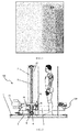
- When an object to be inspected remains stationary and a plane of emitted X-ray beams is moved, since inevitable vibration occurs during motion of certain components, an X-ray generator cannot remain at rest relative to a detector during the scanning process. This may lead to an unstable intensity of X-rays received by the detector. In this case, if traditional correction approaches are employed to process an acquired image (comprising for example simple data transmission, noise reduction processing and analysis, as commonly used), stripe noise will inevitably occur in the image, as shown in
FIG. 1 . - The present invention provides an X-ray scanning method and system to solve the noise issue in the prior art, which is caused by mechanical vibration in existing X-ray scanning process for static object.
- To solve the above problems, the present invention provides an X-ray scanning method, comprising:
- collecting background data when no X-ray is emitted;
- collecting air data when X-rays are emitted and there is no object to be scanned in an inspection channel;
- scanning an object to collect original scanning data; and
- preprocessing the original scanning data according to the background data and the air data to acquire scanned image data.
- Preferably, the step of collecting the background data may further comprise:
- averaging the background data to acquire averaged background data.
- Preferably, the step of collecting the air data may further comprise:
- averaging the air data to acquire averaged air data.
- Preferably, the step of preprocessing the original scanning data according to the background data and the air data to acquire scanned image data may further comprise:
- segmenting a scanning region into an object region containing therein the object and
- an air region without the object according to the original scanning data; and
- searching the air data for particular air data closest to a value of original scanning data for the air region, and performing a gain correction for the original scanning data according to the background data and the closest air data to acquire the scanned image data.
- Preferably, the step of segmenting the scanning region into the object region containing therein the object and the air region without the object according to the original scanning data may comprise: segmenting the scanning region into the object region containing therein the object and the air region without the object by using a predefined threshold.
- Preferably, the step of segmenting the scanning region into the object region containing therein the object and the air region without the object according to the original scanning data may also comprise: segmenting the scanning region into the object region containing therein the object and the air region without the object by using a thresholding method, an edge detection method, or a region growing method.
- Preferably, the step of preprocessing the original scanning data according to the background data and the air data to acquire scanned image data may further comprise:
- defining a sub-region of the scanning region in which no object is allowed to be placed as the air region, and defining the rest of the scanning region as the object region; and
- searching the air data for particular air data closest to a value of original scanning data for the air region, and performing a gain correction for the original scanning data according to the background data and the closest air data to acquire the scanned image data.
- According to another aspect, the present invention also provides an X-ray scanning system, comprising:
- an X-ray generator, adapted for emitting X-rays;
- a detector that remains stationary relative to the X-ray generator, adapted for collecting detecting signals of the X-rays; and
- a processor coupled to the detector, adapted for processing the detecting signals of the X-rays that are collected by the detector, said processing comprises:
- employing the detecting signals collected by the detector when the X-ray generator emits no X-ray as background data;
- employing the detecting signals collected by the detector when the X-ray generator emits the X-rays and there is no object to be scanned in an inspection channel as air data;
- employing the detecting signals collected by the detector when the X-ray generator emits the X-rays to scan an object as original scanning data; and preprocessing the original scanning data according to the background data and the air data to acquire scanned image data.
- Preferably, the processor is further adapted for:
- averaging the background data to acquire averaged background data; and/or
- averaging the air data to acquire averaged air data.
- Preferably, the system may further comprise:
- a collimator, which is fixed in an optical path between the X-ray generator and the detector, wherein the collimator remains stationary relative to both the X-ray generator and the detector, adapted for collimating the X-rays emitted by the X-ray generator.
- Preferably, the processor is further adapted for:
- segmenting a scanning region into an object region containing therein the object and
- an air region without the object according to the original scanning data; and
- searching the air data for particular air data closest to a value of original scanning data for the air region, and performing a gain correction for the original scanning data according to the background data and the closest air data to acquire the scanned image data.
- Preferably, the processor is further adapted for:
- segmenting the scanning region into the object region containing therein the object and the air region without the object by using a predefined threshold.
- Preferably, the processor is further adapted for: segmenting the scanning region into the object region containing therein the object and the air region without the object by using a thresholding method, an edge detection method, or a region growing method.
- Preferably, the processor is further adapted for:
- defining a sub-region of the scanning region in which no object is allowed to be placed as the air region, and defining the rest of the scanning region as the object region; and
- searching the air data for particular air data closest to a value of original scanning data for the air region, and performing a gain correction for the original scanning data according to the background data and the closest air data to acquire the scanned image data.
- Therefore, when performing an X-ray scanning for a static object, the X-ray scanning method and scanning system according to the embodiments of the present invention measure the background data and the air data and process the scanning data, thereby solving the noise problem caused by the mechanical vibration and thus improving the measurement accuracy.
- To illustrate the technical solutions in the embodiments of the present invention or the prior art more clearly, the following briefly introduces the accompanying drawings required for describing the embodiments of the invention or the prior art. Apparently, the accompanying drawings in the following description show merely some embodiments of the present invention, and persons of ordinary skill in the art may still derive other drawings from these accompanying drawings without innovative efforts.
-
FIG. 1 is an exemplary diagram of stripe noise generated in the prior art; -
FIG. 2 is a structural diagram of a human-body security inspection system; -
FIG. 3 is a basic flow diagram of an X-ray scanning method in accordance with embodiments of the present invention; -
FIG. 4 is a flow diagram of an X-ray human-body scanning method in accordance with Example 1 of the present invention; -
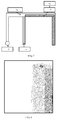
FIG. 5 is an exemplary diagram of a segmentation of object region and air region in accordance with Example 1 of the present invention; -
FIG. 6 is an exemplary diagram of a method for restricting a scanning region in accordance with Example 1 of the present invention; -
FIG. 7 is a structural diagram of an X-ray scanning system in accordance with Example 2 of the present invention; and -
FIG. 8 is an exemplary diagram of a scanned image in accordance with the embodiments of the present invention. - In order to make objects, technical solutions and advantages of the embodiments of the invention more apparent, the technical solutions of the embodiments of the present invention will be described in a clearly and fully understandable way in connection with the drawings related to the embodiments of the present invention. Apparently, the described embodiments are just a part but not all of the embodiments of the invention. Based on the described embodiments herein, those skilled in the art can obtain other embodiment(s), without any inventive work, which should be within the scope of the invention.
-
FIG. 2 shows a human-body security inspection system which may move a plane of emitted X-ray beams while an object to be inspected remains stationary. The system comprises: a pedestal 1, apost 2 supported on the pedestal 1, acollimator mounting face 3, a synchronous belt 4,synchronous pulleys 5, abearing block 6, anintegral arm 7, anut 25, aslider 26, aguide rail 27, anelectric motor 28 and acollimator adjusting device 29, and a scanning andimaging apparatus 150 that is drivable and connected to thepost 2. The human-body security inspection system may comprise adriving device 100 for driving the scanning andimaging apparatus 150 to move along a predetermined direction (such as a vertical direction as shown inFIG. 2 ) so as to perform the scanning process. InFIG. 2 , an X-ray source, a collimator and a detector of the scanning andimaging apparatus 150 are fixedly connected to each other through theintegral arm 7 so as to form an integrated structure. - Referring to
FIG. 3 , an X-ray scanning method is provided in accordance with the embodiment of the present invention, which comprises: - Step 301: collecting background data when no X-ray is emitted;
- Step 302: collecting air data when X-rays are emitted and there is no object to be scanned in an inspection channel;
- Step 303: scanning an object to collect original scanning data; and
- Step 304: preprocessing the original scanning data according to the background data and the air data to acquire scanned image data.
- Furthermore, in the step of collecting the air data when X-rays are emitted and there is no object to be scanned in an inspection channel, an X-ray generator, a detector and the plane of X-ray beams emitted from the X-ray generator are moving during the scanning process.
- In order to have a more accurate measurement, the collected background data and/or air data may be averaged. Preferably, the method may comprise: averaging the background data to acquire averaged background data, or averaging the air data to acquire averaged air data.
- Preferably, the step of preprocessing the original scanning data according to the background data and the air data to acquire scanned image data may further comprise:
- segmenting a scanning region into an object region containing therein the object and an air region without the object according to the original scanning data; and
- searching the air data for particular air data closest to a value of original scanning data for the air region, and performing a gain correction for the original scanning data according to the background data and the closest air data to acquire the scanned image data.
- Preferably, the step of segmenting the scanning region into the object region containing therein the object and the air region without the object according to the original scanning data may comprise: segmenting the scanning region into the object region containing therein the object and the air region without the object by using a predefined threshold.
- Preferably, the step of segmenting the scanning region into the object region containing therein the object and the air region without the object according to the original scanning data may also comprise: segmenting the scanning region into the object region containing therein the object and the air region without the object by using a thresholding method, an edge detection method, or a region growing method.
- Furthermore, the thresholding method may be used to distinguish the gray level thresholds of target (i.e., the object region) and background (i.e., the air region). If an image only comprises target and background, the method may select a single threshold, also known as single threshold segmentation. The segmentation using the predefined threshold is one kind of single threshold segmentations. The edge detection method is the most popular detection method for gray level discontinuity. This method is based on the original scanning data and uses a first-order derivative and/or a second-order derivative to detect the gray level discontinuity of the image, such that the object region and the air region of the image may be segmented. Basic principle of the region growing method is to gather pixels with similar property to construct a region. It begins with choosing a seed point (i.e., a seed pixel), and subsequently merging similar pixels around the seed pixel into a region containing the seed pixel. As a result, the object region and the air region of the original scanning data may be obtained respectively.
- Preferably, the step of preprocessing the original scanning data according to the background data and the air data to acquire scanned image data may further comprise:
- defining a sub-region of the scanning region in which no object is allowed to be placed as the air region, and defining the rest of the scanning region as the object region; and
- searching the air data for particular air data closest to a value of original scanning data for the air region, and performing a gain correction for the original scanning data according to the background data and the closest air data to acquire the scanned image data.
- Example 1 of the present invention provides an X-ray scanning method, which is adapted for human-body scanning. In a case where a plane of emitted X-ray beams is fixed while a person to be inspected passes through the plane of emitted X-ray beams by standing on a conveying belt, since it is not easy for the person to keep balance when he/she moves, his/her body-shaking will impact the inspection effect. Therefore, in a scanning process of the Example 1, the person to be inspected stands on a designated fixed location, and the scanning process is performed by moving an X-ray generator and a detector (their relative position is fixed) in a direction vertical to the plane of emitted X-ray beams. During this scanning process, the only thing to do by the person to be inspected is to keep still.
- Particularly, referring to
FIG. 4 , in order to correct stripe noise (which is caused by mechanical vibration during the scanning process) on images, the scanning method of Example 1 of the present invention may comprise: - Step 401: collecting background data when no X-ray is emitted and averaging the background data.
- In this step, the background data is collected when no X-ray is emitted. Because no X-ray will be generated during the collection of the background data, the problem that the X-rays received by the detector have the unstable intensity due to the mechanical vibration during the scanning process will not arise.
- During the collection of the background data collection, the background data may be collected for a period of time and then averaged. Averaged background data is denoted by Z(j), wherein j = 1, ..., n, and j represents a serial number of a channel of the detector.
- Step 402: collecting air data when X-rays are emitted and there is no object to be scanned in an inspection channel, and averaging the air data.
- In this step, the air data is collected when the X-rays are emitted and there is no object to be scanned in the inspection channel. The air data obtained by scanning will be used in a gain correction for the detector. Since mechanical vibration occurs during the scanning process, the air data will have a large fluctuation. During this collection, the X-ray generator and the detector move in a direction vertical to the plane of emitted X-ray beams to perform a no-object scanning, i.e., there is no object placed in the scanning channel. As a result, a set of air data F(i, j) will be obtained, wherein i = 1, ..., m, and j = 1, ..., n. Furthermore, "i" represents a serial number of a sampling time, and there are m rows of data obtained during the scanning process; and "j" represents a serial number of a channel of the detector, and there are n detector channels in total. Moreover, m and n may also represent a height and a width of the scanned image, respectively.
- Thereafter, the obtained air data F(i, j) may be averaged over all the rows, which results in averaged air data

- Step 403: scanning a human body to collect original scanning data.
- In this step, the original scanning data is collected by moving the X-ray generator and the detector to perform a normal scanning for the human body that remains stationary. The original data obtained during the scanning process for the human body is denoted by R(i, j), wherein i = 1, ..., m, and j = 1, ..., n.
- Step 404: preprocessing the original scanning data according to the background data and the air data to acquire scanned image data.
- Background correction and gain correction (i.e., data preprocessing) will be performed for the obtained original scanning data according to the averaged background data and the averaged air data. The preprocessed image is denoted by N(i, j). The calculation of N(i, j) will be explained in detail as below.
- First, the original scanning data is preprocessed according to the averaged background data and the averaged air data. Particularly, for each sampling time i, T(i, j) will be calculated according to the following equation:

- On the basis of T(i, j), for the original scanning data obtained at each sampling time, the acquired scanned image may be segmented into an object region containing therein the human body and an air region without the human body (referring to
FIG. 5 ). - The region segmentation may simply employ a predefined threshold t. Particularly, regions whose values are larger than t are defined as air region, and regions whose values are no larger than t are defined as object region. Alternatively, any other image segmentation methods may be employed, such as thresholding method, edge detection method, region growing method, etc. For each row i, a set of column coordinates of the corresponding air region may be denoted by Ai. That is to say, during the scanning of the i-th row of the original scanning data, there is no object in these columns in the set Ai to absorb the X-rays. Therefore, the corresponding scanning data for these columns shall be regarded as air data as a result of scanning the air. For these columns in the set Ai, a row ki which is closest to the value of original scanning data is searched from the air data F(i, j):

- For the set Ai of columns of the air data, the value of the i-th row of the original scanning data is closest to the value of the ki-th row of the air data. In the present embodiment, the distance between vectors is measured in Euclidean distance. Alternatively, depending on practical situations, the distance between vectors may be measured in other manners such as city block distance, chessboard distance, etc. Herein, it can be assumed that, despite the mechanical vibration and the data fluctuation, the status of the whole system in the scanning of the i-th row of the original scanning data is closest to that in the scanning of the ki-th row of the air data. Therefore, the ki-th row of the air data may be used in the correction of the i-th row of the original scanning data as follows:

- The above correction method is more reasonable than the correction method using the averaged air data F(j), and is capable of removing striped noise resulted from the latter.
- Herein, the size of the set Ai is a factor that influences the correction effect. In order to ensure that Ai comprises a sufficient number of columns, a width of detectable range of the detector may be appropriately increased or the scanning region may be defined to ensure a sufficient size of the air region. For example, certain regions may be marked out at either side or both sides of the scanning tunnels. These regions are also within the scope of scanning and imaging, but it is not allowed to place the object to be scanned or other objects within these regions (as shown in
FIG. 6 ). As such, the image segmentation may be omitted, and the portion of the image corresponding to these regions in which objects are not allowed to be placed may be directly viewed as the air region. - Referring to
FIG. 7 , Example 2 of the present invention provides an X-ray scanning system, which comprises: - an
X-ray generator 71, adapted for emitting X-rays; - a
detector 72 that remains stationary relative to the X-ray generator, adapted for collecting detecting signals of the X-rays; and - a
processor 73 coupled to thedetector 72, adapted for processing the detecting signals of the X-rays that are collected by thedetector 72, said processing comprises:- employing the detecting signals collected by the detector when the X-ray generator emits no X-ray as background data;
- employing the detecting signals collected by the detector when the X-ray generator emits the X-rays and there is no object to be scanned in an inspection channel as air data;
- employing the detecting signals collected by the detector when the X-ray generator emits the X-rays to scan an object as original scanning data; and preprocessing the original scanning data according to the background data and the air data to acquire scanned image data.
- Furthermore, in order to scan an object to be inspected while the object remains relatively stationary, both the
X-ray generator 71 and thedetector 72 may be installed on a fixedsupport 74 and driven by a driving device. Accordingly, the scanning process can be performed in such a way that theX-ray generator 71 and thedetector 72 can be moved along a direction vertical to a plane of emitted beams while theX-ray generator 71 remains stationary relative to thedetector 72. - Preferably, the
processor 73 is further adapted for: - averaging the background data to acquire averaged background data; and/or
- averaging the air data to acquire averaged air data.
- Preferably, the system may also comprises a
collimator 75, which is fixed in an optical path between theX-ray generator 71 and thedetector 72, wherein thecollimator 75 remains stationary relative to both theX-ray generator 71 and thedetector 72, adapted for collimating the X-rays emitted by theX-ray generator 71. - Preferably, the
processor 73 is further adapted for: - segmenting a scanning region into an object region containing therein the object and an air region without the object according to the original scanning data; and
- searching the air data for particular air data closest to a value of original scanning data for the air region, and performing a gain correction for the original scanning data according to the background data and the closest air data to acquire the scanned image data.
- Preferably, the
processor 73 is further adapted for: - segmenting the scanning region into the object region containing therein the object and the air region without the object by using a predefined threshold.
- Preferably, the
processor 73 is further adapted for: segmenting the scanning region into the object region containing therein the object and the air region without the object by using a thresholding method, an edge detection method, or a region growing method. - Preferably, the
processor 73 is further adapted for: - defining a sub-region of the scanning region in which no object is allowed to be placed as the air region, and defining the rest of the scanning region as the object region; and
- searching the air data for particular air data closest to a value of original scanning data for the air region, and performing a gain correction for the original scanning data according to the background data and the closest air data to acquire the scanned image data.
-
FIG. 8 shows a scanned image obtained after the X-ray scanning and data processing for a static object by the X-ray scanning method and scanning system in accordance with the embodiments of the present invention. As can be clearly seen from a comparison between the images shown inFIG. 8 andFIG. 1 , the stripe noise appeared in an empty region on the left side and a scanned object region on the right side of the image ofFIG. 1 have been efficiently suppressed and removed from the image ofFIG. 8 . - Therefore, when performing an X-ray scanning for a static object, the X-ray scanning method and scanning system according to the embodiments of the present invention measure the background data and the air data and process the scanning data, thereby solving the noise problem caused by the mechanical vibration and thus improving the measurement accuracy.
- It should be noted that the above embodiments are merely provided for describing the technical solutions of the present invention, but not intended to limit the present invention. It should be understood by those of ordinary skill in the art that although the present invention is described in detail with reference to the foregoing embodiments, modifications can be made to the technical solutions described in the foregoing embodiments, or equivalent alternations can be made to some technical features in the technical solutions, without substantially departing from the spirit and scope of the technical solutions of the embodiments of the present invention.
Claims (14)
- An X-ray scanning method, characterized in that, comprising:collecting background data when no X-ray is emitted;collecting air data when X-rays are emitted and there is no object to be scanned in an inspection channel;scanning an object to collect original scanning data; andpreprocessing the original scanning data according to the background data and the air data to acquire scanned image data.
- The X-ray scanning method according to claim 1, characterized in that, the step of collecting the background data further comprises:averaging the background data to acquire averaged background data.
- The X-ray scanning method according to claim 1, characterized in that, the step of collecting the air data further comprises:averaging the air data to acquire averaged air data.
- The X-ray scanning method according to any of claims 1-3, characterized in that, the step of preprocessing the original scanning data according to the background data and the air data to acquire scanned image data further comprises:segmenting a scanning region into an object region containing therein the object and an air region without the object according to the original scanning data; andsearching the air data for particular air data closest to a value of original scanning data for the air region, and performing a gain correction for the original scanning data according to the background data and the closest air data to acquire the scanned image data.
- The X-ray scanning method according to claim 4, characterized in that, the step of segmenting the scanning region into the object region containing therein the object and the air region without the object according to the original scanning data comprises:segmenting the scanning region into the object region containing therein the object and the air region without the object by using a predefined threshold.
- The X-ray scanning method according to claim 4, characterized in that, the step of segmenting the scanning region into the object region containing therein the object and the air region without the object according to the original scanning data comprises:segmenting the scanning region into the object region containing therein the object and the air region without the object by using a thresholding method, an edge detection method, or a region growing method.
- The X-ray scanning method according to any of claims 1-3, characterized in that, the step of preprocessing the original scanning data according to the background data and the air data to acquire scanned image data further comprises:defining a sub-region of the scanning region in which no object is allowed to be placed as the air region, and defining the rest of the scanning region as the object region; andsearching the air data for particular air data closest to a value of original scanning data for the air region, and performing a gain correction for the original scanning data according to the background data and the closest air data to acquire the scanned image data.
- An X-ray scanning system, characterized in that, said system comprising:an X-ray generator (71) adapted for emitting X-rays;a detector (72) that remains stationary relative to the X-ray generator (71), adapted for collecting detecting signals of the X-rays; anda processor (73) coupled to the detector (72), adapted for processing the detecting signals of the X-rays that are collected by the detector (72), said processing comprises:employing the detecting signals collected by the detector (72) when the X-ray generator (71) emits no X-ray as background data;employing the detecting signals collected by the detector (72) when the X-ray generator (71) emits the X-rays and there is no object to be scanned in an inspection channel as air data;employing the detecting signals collected by the detector (72) when the X-ray generator (71) emits the X-rays to scan an object as original scanning data; andpreprocessing the original scanning data according to the background data and the air data to acquire scanned image data.
- The X-ray scanning system according to claim 8, characterized in that, the processor (73) is further adapted for:averaging the background data to acquire averaged background data; and/oraveraging the air data to acquire averaged air data.
- The X-ray scanning system according to claim 8, further comprising:a collimator (75), which is fixed in an optical path between the X-ray generator (71) and the detector (72), wherein the collimator (75) remains stationary relative to both the X-ray generator (71) and the detector (72), adapted for collimating the X-rays emitted by the X-ray generator (71).
- The X-ray scanning system according to any of claims 8-10, characterized in that, the processor (73) is further adapted for:segmenting a scanning region into an object region containing therein the object and an air region without the object according to the original scanning data; andsearching the air data for particular air data closest to a value of original scanning data for the air region, and performing a gain correction for the original scanning data according to the background data and the closest air data to acquire the scanned image data.
- The X-ray scanning system according to claim 11, characterized in that, the processor (73) is further adapted for:segmenting the scanning region into the object region containing therein the object and the air region without the object by using a predefined threshold.
- The X-ray scanning system according to claim 11, characterized in that, the processor (73) is further adapted for:segmenting the scanning region into the object region containing therein the object and the air region without the object by using a thresholding method, an edge detection method, or a region growing method.
- The X-ray scanning system according to any of claims 8-10, characterized in that, the processor (73) is further adapted for:defining a sub-region of the scanning region in which no object is allowed to be placed as the air region, and defining the rest of the scanning region as the object region; and searching the air data for particular air data closest to a value of original scanning data for the air region, and performing a gain correction for the original scanning data according to the background data and the closest air data to acquire the scanned image data.
Applications Claiming Priority (1)
| Application Number | Priority Date | Filing Date | Title |
|---|---|---|---|
| CN201510162286.8A CN104777178B (en) | 2015-04-07 | 2015-04-07 | A kind of X-ray scanning method and scanning system |
Publications (2)
| Publication Number | Publication Date |
|---|---|
| EP3078990A1 true EP3078990A1 (en) | 2016-10-12 |
| EP3078990B1 EP3078990B1 (en) | 2019-07-24 |
Family
ID=53618781
Family Applications (1)
| Application Number | Title | Priority Date | Filing Date |
|---|---|---|---|
| EP16158305.9A Active EP3078990B1 (en) | 2015-04-07 | 2016-03-02 | X-ray scanning method and system |
Country Status (8)
| Country | Link |
|---|---|
| US (1) | US10042080B2 (en) |
| EP (1) | EP3078990B1 (en) |
| JP (1) | JP6131355B2 (en) |
| CN (1) | CN104777178B (en) |
| AU (1) | AU2016201324B2 (en) |
| BR (1) | BR102016004776B1 (en) |
| MY (1) | MY188044A (en) |
| RU (1) | RU2629059C1 (en) |
Families Citing this family (9)
| Publication number | Priority date | Publication date | Assignee | Title |
|---|---|---|---|---|
| CN106249307B (en) * | 2016-07-22 | 2018-12-28 | 同方威视技术股份有限公司 | Safety detection method and system |
| CN106054271B (en) * | 2016-07-22 | 2020-02-07 | 同方威视技术股份有限公司 | Security check method and system |
| CN106570836A (en) * | 2016-11-03 | 2017-04-19 | 北京航星机器制造有限公司 | Radiation image local enhancement method |
| CN110274923B (en) * | 2019-07-22 | 2020-10-09 | 中国原子能科学研究院 | Synchronous data acquisition and calibration method and control system of high-energy X-ray CT equipment |
| CN111012370A (en) * | 2019-12-25 | 2020-04-17 | 四川大学华西医院 | AI-based X-ray imaging analysis method, device and readable storage medium |
| CN113835131A (en) * | 2020-06-23 | 2021-12-24 | 同方威视技术股份有限公司 | Automatic walking type inspection device and automatic vehicle separation method |
| CN113835130A (en) * | 2020-06-23 | 2021-12-24 | 同方威视技术股份有限公司 | Automatic walking type inspection device and automatic vehicle separation method |
| CN119379840B (en) * | 2024-12-26 | 2025-04-01 | 杭州睿影科技有限公司 | Security inspection image processing method, device and electronic equipment |
| CN119846731B (en) * | 2025-03-17 | 2025-08-01 | 杭州睿影科技有限公司 | Security check image display method and device and control equipment |
Citations (3)
| Publication number | Priority date | Publication date | Assignee | Title |
|---|---|---|---|---|
| WO1992002892A1 (en) * | 1990-08-10 | 1992-02-20 | Vivid Technologies, Inc. | Device and method for inspection of baggage and other objects |
| US5949842A (en) * | 1997-10-10 | 1999-09-07 | Analogic Corporation | Air calibration scan for computed tomography scanner with obstructing objects |
| CN102567960A (en) * | 2010-12-31 | 2012-07-11 | 同方威视技术股份有限公司 | An image enhancement method for security inspection system |
Family Cites Families (10)
| Publication number | Priority date | Publication date | Assignee | Title |
|---|---|---|---|---|
| EP1019708A4 (en) * | 1997-10-10 | 2001-01-10 | Analogic Corp | Ct target detection using surface normals |
| US6459761B1 (en) | 2000-02-10 | 2002-10-01 | American Science And Engineering, Inc. | Spectrally shaped x-ray inspection system |
| RU2261465C2 (en) | 2000-08-28 | 2005-09-27 | Научно-Производственное Частное Унитарное Предприятие Адани | Method for x-ray control of body (variants) and plant for realization of said method (variants) |
| WO2007051092A2 (en) | 2005-10-24 | 2007-05-03 | American Science And Engineering, Inc. | X-ray inspection based on scatter detection |
| RU2418291C2 (en) | 2005-10-24 | 2011-05-10 | Эмерикэн Сайэнс Энд Энджиниэринг, Инк. | Object inspection method (versions) and system |
| CN101672805B (en) * | 2008-09-11 | 2012-03-28 | 同方威视技术股份有限公司 | Method for updating correction table, method for correcting detection data, and safety inspection system |
| JP2010185888A (en) * | 2010-06-02 | 2010-08-26 | Hitachi Ltd | Radiation nondestructive inspection system and piping inspection method |
| JP2015118074A (en) * | 2013-12-20 | 2015-06-25 | キヤノン株式会社 | X-ray tomography apparatus and X-ray tomography method |
| WO2016147314A1 (en) | 2015-03-17 | 2016-09-22 | 株式会社日立製作所 | Computer tomographic imaging method and device |
| CN204495747U (en) * | 2015-04-07 | 2015-07-22 | 同方威视技术股份有限公司 | A kind of X-ray scanning system |
-
2015
- 2015-04-07 CN CN201510162286.8A patent/CN104777178B/en active Active
-
2016
- 2016-03-01 AU AU2016201324A patent/AU2016201324B2/en not_active Ceased
- 2016-03-02 EP EP16158305.9A patent/EP3078990B1/en active Active
- 2016-03-03 BR BR102016004776-5A patent/BR102016004776B1/en active IP Right Grant
- 2016-03-04 MY MYPI2016700763A patent/MY188044A/en unknown
- 2016-03-04 US US15/061,854 patent/US10042080B2/en active Active
- 2016-03-08 JP JP2016044778A patent/JP6131355B2/en active Active
- 2016-03-22 RU RU2016110461A patent/RU2629059C1/en not_active IP Right Cessation
Patent Citations (3)
| Publication number | Priority date | Publication date | Assignee | Title |
|---|---|---|---|---|
| WO1992002892A1 (en) * | 1990-08-10 | 1992-02-20 | Vivid Technologies, Inc. | Device and method for inspection of baggage and other objects |
| US5949842A (en) * | 1997-10-10 | 1999-09-07 | Analogic Corporation | Air calibration scan for computed tomography scanner with obstructing objects |
| CN102567960A (en) * | 2010-12-31 | 2012-07-11 | 同方威视技术股份有限公司 | An image enhancement method for security inspection system |
Also Published As
| Publication number | Publication date |
|---|---|
| JP6131355B2 (en) | 2017-05-17 |
| JP2016200582A (en) | 2016-12-01 |
| AU2016201324B2 (en) | 2017-03-16 |
| US10042080B2 (en) | 2018-08-07 |
| US20160299250A1 (en) | 2016-10-13 |
| CN104777178B (en) | 2017-08-25 |
| AU2016201324A1 (en) | 2016-10-27 |
| BR102016004776A2 (en) | 2016-10-11 |
| MY188044A (en) | 2021-11-11 |
| EP3078990B1 (en) | 2019-07-24 |
| BR102016004776B1 (en) | 2021-12-28 |
| RU2629059C1 (en) | 2017-08-24 |
| CN104777178A (en) | 2015-07-15 |
Similar Documents
| Publication | Publication Date | Title |
|---|---|---|
| EP3078990B1 (en) | X-ray scanning method and system | |
| US10527525B2 (en) | Method and system for fast inspecting vehicle based on measure lengths | |
| US8633823B2 (en) | Systems and methods for automated, rapid detection of high-atomic-number materials | |
| EP3388868B1 (en) | Inspection devices and methods for inspecting a container | |
| EP2482060A1 (en) | Radiation inspection device for object security inspection and inspection method thereof | |
| US20100193700A1 (en) | Spectral photon counting detector | |
| US7539337B2 (en) | Method of and system for splitting compound objects in multi-energy computed tomography images | |
| KR20080113012A (en) | Radiation detector and radiation detection method | |
| CN1947001A (en) | Elimination of crosstalk in the inlet for backscatter checks involving multiple sources by ensuring only one source is emitting radiation at a time | |
| US20250325242A1 (en) | Correction of images and depth information for detection with matrix | |
| EP2910980A1 (en) | Human body back scatterning inspection method and system | |
| US7801348B2 (en) | Method of and system for classifying objects using local distributions of multi-energy computed tomography images | |
| US20150106056A1 (en) | Surface shape measuring method and surface shape measuring device | |
| CN204495747U (en) | A kind of X-ray scanning system | |
| US20170024862A1 (en) | Method and system for estimating point spread function | |
| US7388983B2 (en) | Method of and system for detecting anomalies in projection images generated by computed tomography scanners | |
| KR101492185B1 (en) | Apparatus for measuring snowfall | |
| US12567226B2 (en) | Method and device of acquiring feature information of detected object, apparatus and medium | |
| KR20070054650A (en) | Coherent Scattering Image Processing | |
| CN111492417A (en) | System for screening cargo and self-propelled vehicles and automatic radiological observation control method for moving objects for determining a radiation scanning area in a screening system | |
| HK1104181B (en) | Eliminating cross-talk in a backscatter inspection portal comprising multiples sources by ensuring that only one source is emitting radiation at a time |
Legal Events
| Date | Code | Title | Description |
|---|---|---|---|
| PUAI | Public reference made under article 153(3) epc to a published international application that has entered the european phase |
Free format text: ORIGINAL CODE: 0009012 |
|
| AK | Designated contracting states |
Kind code of ref document: A1 Designated state(s): AL AT BE BG CH CY CZ DE DK EE ES FI FR GB GR HR HU IE IS IT LI LT LU LV MC MK MT NL NO PL PT RO RS SE SI SK SM TR |
|
| AX | Request for extension of the european patent |
Extension state: BA ME |
|
| STAA | Information on the status of an ep patent application or granted ep patent |
Free format text: STATUS: REQUEST FOR EXAMINATION WAS MADE |
|
| 17P | Request for examination filed |
Effective date: 20170113 |
|
| RBV | Designated contracting states (corrected) |
Designated state(s): AL AT BE BG CH CY CZ DE DK EE ES FI FR GB GR HR HU IE IS IT LI LT LU LV MC MK MT NL NO PL PT RO RS SE SI SK SM TR |
|
| GRAP | Despatch of communication of intention to grant a patent |
Free format text: ORIGINAL CODE: EPIDOSNIGR1 |
|
| STAA | Information on the status of an ep patent application or granted ep patent |
Free format text: STATUS: GRANT OF PATENT IS INTENDED |
|
| RIC1 | Information provided on ipc code assigned before grant |
Ipc: G01T 1/29 20060101AFI20190124BHEP Ipc: G01V 5/00 20060101ALI20190124BHEP |
|
| INTG | Intention to grant announced |
Effective date: 20190222 |
|
| GRAS | Grant fee paid |
Free format text: ORIGINAL CODE: EPIDOSNIGR3 |
|
| GRAA | (expected) grant |
Free format text: ORIGINAL CODE: 0009210 |
|
| STAA | Information on the status of an ep patent application or granted ep patent |
Free format text: STATUS: THE PATENT HAS BEEN GRANTED |
|
| AK | Designated contracting states |
Kind code of ref document: B1 Designated state(s): AL AT BE BG CH CY CZ DE DK EE ES FI FR GB GR HR HU IE IS IT LI LT LU LV MC MK MT NL NO PL PT RO RS SE SI SK SM TR |
|
| REG | Reference to a national code |
Ref country code: GB Ref legal event code: FG4D |
|
| REG | Reference to a national code |
Ref country code: CH Ref legal event code: EP |
|
| REG | Reference to a national code |
Ref country code: DE Ref legal event code: R096 Ref document number: 602016017170 Country of ref document: DE |
|
| REG | Reference to a national code |
Ref country code: AT Ref legal event code: REF Ref document number: 1158847 Country of ref document: AT Kind code of ref document: T Effective date: 20190815 |
|
| REG | Reference to a national code |
Ref country code: IE Ref legal event code: FG4D |
|
| REG | Reference to a national code |
Ref country code: NL Ref legal event code: MP Effective date: 20190724 |
|
| REG | Reference to a national code |
Ref country code: LT Ref legal event code: MG4D |
|
| REG | Reference to a national code |
Ref country code: AT Ref legal event code: MK05 Ref document number: 1158847 Country of ref document: AT Kind code of ref document: T Effective date: 20190724 |
|
| PG25 | Lapsed in a contracting state [announced via postgrant information from national office to epo] |
Ref country code: NO Free format text: LAPSE BECAUSE OF FAILURE TO SUBMIT A TRANSLATION OF THE DESCRIPTION OR TO PAY THE FEE WITHIN THE PRESCRIBED TIME-LIMIT Effective date: 20191024 Ref country code: AT Free format text: LAPSE BECAUSE OF FAILURE TO SUBMIT A TRANSLATION OF THE DESCRIPTION OR TO PAY THE FEE WITHIN THE PRESCRIBED TIME-LIMIT Effective date: 20190724 Ref country code: LT Free format text: LAPSE BECAUSE OF FAILURE TO SUBMIT A TRANSLATION OF THE DESCRIPTION OR TO PAY THE FEE WITHIN THE PRESCRIBED TIME-LIMIT Effective date: 20190724 Ref country code: PT Free format text: LAPSE BECAUSE OF FAILURE TO SUBMIT A TRANSLATION OF THE DESCRIPTION OR TO PAY THE FEE WITHIN THE PRESCRIBED TIME-LIMIT Effective date: 20191125 Ref country code: NL Free format text: LAPSE BECAUSE OF FAILURE TO SUBMIT A TRANSLATION OF THE DESCRIPTION OR TO PAY THE FEE WITHIN THE PRESCRIBED TIME-LIMIT Effective date: 20190724 Ref country code: BG Free format text: LAPSE BECAUSE OF FAILURE TO SUBMIT A TRANSLATION OF THE DESCRIPTION OR TO PAY THE FEE WITHIN THE PRESCRIBED TIME-LIMIT Effective date: 20191024 Ref country code: FI Free format text: LAPSE BECAUSE OF FAILURE TO SUBMIT A TRANSLATION OF THE DESCRIPTION OR TO PAY THE FEE WITHIN THE PRESCRIBED TIME-LIMIT Effective date: 20190724 Ref country code: HR Free format text: LAPSE BECAUSE OF FAILURE TO SUBMIT A TRANSLATION OF THE DESCRIPTION OR TO PAY THE FEE WITHIN THE PRESCRIBED TIME-LIMIT Effective date: 20190724 Ref country code: SE Free format text: LAPSE BECAUSE OF FAILURE TO SUBMIT A TRANSLATION OF THE DESCRIPTION OR TO PAY THE FEE WITHIN THE PRESCRIBED TIME-LIMIT Effective date: 20190724 |
|
| PG25 | Lapsed in a contracting state [announced via postgrant information from national office to epo] |
Ref country code: ES Free format text: LAPSE BECAUSE OF FAILURE TO SUBMIT A TRANSLATION OF THE DESCRIPTION OR TO PAY THE FEE WITHIN THE PRESCRIBED TIME-LIMIT Effective date: 20190724 Ref country code: GR Free format text: LAPSE BECAUSE OF FAILURE TO SUBMIT A TRANSLATION OF THE DESCRIPTION OR TO PAY THE FEE WITHIN THE PRESCRIBED TIME-LIMIT Effective date: 20191025 Ref country code: LV Free format text: LAPSE BECAUSE OF FAILURE TO SUBMIT A TRANSLATION OF THE DESCRIPTION OR TO PAY THE FEE WITHIN THE PRESCRIBED TIME-LIMIT Effective date: 20190724 Ref country code: AL Free format text: LAPSE BECAUSE OF FAILURE TO SUBMIT A TRANSLATION OF THE DESCRIPTION OR TO PAY THE FEE WITHIN THE PRESCRIBED TIME-LIMIT Effective date: 20190724 Ref country code: IS Free format text: LAPSE BECAUSE OF FAILURE TO SUBMIT A TRANSLATION OF THE DESCRIPTION OR TO PAY THE FEE WITHIN THE PRESCRIBED TIME-LIMIT Effective date: 20191124 Ref country code: RS Free format text: LAPSE BECAUSE OF FAILURE TO SUBMIT A TRANSLATION OF THE DESCRIPTION OR TO PAY THE FEE WITHIN THE PRESCRIBED TIME-LIMIT Effective date: 20190724 |
|
| PG25 | Lapsed in a contracting state [announced via postgrant information from national office to epo] |
Ref country code: TR Free format text: LAPSE BECAUSE OF FAILURE TO SUBMIT A TRANSLATION OF THE DESCRIPTION OR TO PAY THE FEE WITHIN THE PRESCRIBED TIME-LIMIT Effective date: 20190724 |
|
| PG25 | Lapsed in a contracting state [announced via postgrant information from national office to epo] |
Ref country code: IT Free format text: LAPSE BECAUSE OF FAILURE TO SUBMIT A TRANSLATION OF THE DESCRIPTION OR TO PAY THE FEE WITHIN THE PRESCRIBED TIME-LIMIT Effective date: 20190724 Ref country code: DK Free format text: LAPSE BECAUSE OF FAILURE TO SUBMIT A TRANSLATION OF THE DESCRIPTION OR TO PAY THE FEE WITHIN THE PRESCRIBED TIME-LIMIT Effective date: 20190724 Ref country code: EE Free format text: LAPSE BECAUSE OF FAILURE TO SUBMIT A TRANSLATION OF THE DESCRIPTION OR TO PAY THE FEE WITHIN THE PRESCRIBED TIME-LIMIT Effective date: 20190724 Ref country code: PL Free format text: LAPSE BECAUSE OF FAILURE TO SUBMIT A TRANSLATION OF THE DESCRIPTION OR TO PAY THE FEE WITHIN THE PRESCRIBED TIME-LIMIT Effective date: 20190724 Ref country code: RO Free format text: LAPSE BECAUSE OF FAILURE TO SUBMIT A TRANSLATION OF THE DESCRIPTION OR TO PAY THE FEE WITHIN THE PRESCRIBED TIME-LIMIT Effective date: 20190724 |
|
| PG25 | Lapsed in a contracting state [announced via postgrant information from national office to epo] |
Ref country code: IS Free format text: LAPSE BECAUSE OF FAILURE TO SUBMIT A TRANSLATION OF THE DESCRIPTION OR TO PAY THE FEE WITHIN THE PRESCRIBED TIME-LIMIT Effective date: 20200224 Ref country code: SK Free format text: LAPSE BECAUSE OF FAILURE TO SUBMIT A TRANSLATION OF THE DESCRIPTION OR TO PAY THE FEE WITHIN THE PRESCRIBED TIME-LIMIT Effective date: 20190724 Ref country code: CZ Free format text: LAPSE BECAUSE OF FAILURE TO SUBMIT A TRANSLATION OF THE DESCRIPTION OR TO PAY THE FEE WITHIN THE PRESCRIBED TIME-LIMIT Effective date: 20190724 Ref country code: SM Free format text: LAPSE BECAUSE OF FAILURE TO SUBMIT A TRANSLATION OF THE DESCRIPTION OR TO PAY THE FEE WITHIN THE PRESCRIBED TIME-LIMIT Effective date: 20190724 |
|
| REG | Reference to a national code |
Ref country code: DE Ref legal event code: R097 Ref document number: 602016017170 Country of ref document: DE |
|
| PLBE | No opposition filed within time limit |
Free format text: ORIGINAL CODE: 0009261 |
|
| STAA | Information on the status of an ep patent application or granted ep patent |
Free format text: STATUS: NO OPPOSITION FILED WITHIN TIME LIMIT |
|
| PG2D | Information on lapse in contracting state deleted |
Ref country code: IS |
|
| 26N | No opposition filed |
Effective date: 20200603 |
|
| PG25 | Lapsed in a contracting state [announced via postgrant information from national office to epo] |
Ref country code: SI Free format text: LAPSE BECAUSE OF FAILURE TO SUBMIT A TRANSLATION OF THE DESCRIPTION OR TO PAY THE FEE WITHIN THE PRESCRIBED TIME-LIMIT Effective date: 20190724 |
|
| REG | Reference to a national code |
Ref country code: DE Ref legal event code: R119 Ref document number: 602016017170 Country of ref document: DE |
|
| PG25 | Lapsed in a contracting state [announced via postgrant information from national office to epo] |
Ref country code: MC Free format text: LAPSE BECAUSE OF FAILURE TO SUBMIT A TRANSLATION OF THE DESCRIPTION OR TO PAY THE FEE WITHIN THE PRESCRIBED TIME-LIMIT Effective date: 20190724 |
|
| REG | Reference to a national code |
Ref country code: CH Ref legal event code: PL |
|
| REG | Reference to a national code |
Ref country code: BE Ref legal event code: MM Effective date: 20200331 |
|
| PG25 | Lapsed in a contracting state [announced via postgrant information from national office to epo] |
Ref country code: LU Free format text: LAPSE BECAUSE OF NON-PAYMENT OF DUE FEES Effective date: 20200302 |
|
| PG25 | Lapsed in a contracting state [announced via postgrant information from national office to epo] |
Ref country code: LI Free format text: LAPSE BECAUSE OF NON-PAYMENT OF DUE FEES Effective date: 20200331 Ref country code: DE Free format text: LAPSE BECAUSE OF NON-PAYMENT OF DUE FEES Effective date: 20201001 Ref country code: CH Free format text: LAPSE BECAUSE OF NON-PAYMENT OF DUE FEES Effective date: 20200331 Ref country code: FR Free format text: LAPSE BECAUSE OF NON-PAYMENT OF DUE FEES Effective date: 20200331 Ref country code: IE Free format text: LAPSE BECAUSE OF NON-PAYMENT OF DUE FEES Effective date: 20200302 |
|
| PG25 | Lapsed in a contracting state [announced via postgrant information from national office to epo] |
Ref country code: BE Free format text: LAPSE BECAUSE OF NON-PAYMENT OF DUE FEES Effective date: 20200331 |
|
| GBPC | Gb: european patent ceased through non-payment of renewal fee |
Effective date: 20200302 |
|
| PG25 | Lapsed in a contracting state [announced via postgrant information from national office to epo] |
Ref country code: GB Free format text: LAPSE BECAUSE OF NON-PAYMENT OF DUE FEES Effective date: 20200302 |
|
| PG25 | Lapsed in a contracting state [announced via postgrant information from national office to epo] |
Ref country code: MT Free format text: LAPSE BECAUSE OF FAILURE TO SUBMIT A TRANSLATION OF THE DESCRIPTION OR TO PAY THE FEE WITHIN THE PRESCRIBED TIME-LIMIT Effective date: 20190724 Ref country code: CY Free format text: LAPSE BECAUSE OF FAILURE TO SUBMIT A TRANSLATION OF THE DESCRIPTION OR TO PAY THE FEE WITHIN THE PRESCRIBED TIME-LIMIT Effective date: 20190724 |
|
| PG25 | Lapsed in a contracting state [announced via postgrant information from national office to epo] |
Ref country code: MK Free format text: LAPSE BECAUSE OF FAILURE TO SUBMIT A TRANSLATION OF THE DESCRIPTION OR TO PAY THE FEE WITHIN THE PRESCRIBED TIME-LIMIT Effective date: 20190724 |