EP3078980A1 - Dynamic effects correction in medical imaging - Google Patents
Dynamic effects correction in medical imaging Download PDFInfo
- Publication number
- EP3078980A1 EP3078980A1 EP15162610.8A EP15162610A EP3078980A1 EP 3078980 A1 EP3078980 A1 EP 3078980A1 EP 15162610 A EP15162610 A EP 15162610A EP 3078980 A1 EP3078980 A1 EP 3078980A1
- Authority
- EP
- European Patent Office
- Prior art keywords
- image acquisition
- dcm
- commands
- imaging apparatus
- dynamic
- Prior art date
- Legal status (The legal status is an assumption and is not a legal conclusion. Google has not performed a legal analysis and makes no representation as to the accuracy of the status listed.)
- Granted
Links
Images
Classifications
-
- G—PHYSICS
- G06—COMPUTING OR CALCULATING; COUNTING
- G06T—IMAGE DATA PROCESSING OR GENERATION, IN GENERAL
- G06T7/00—Image analysis
- G06T7/0002—Inspection of images, e.g. flaw detection
- G06T7/0012—Biomedical image inspection
-
- G—PHYSICS
- G01—MEASURING; TESTING
- G01R—MEASURING ELECTRIC VARIABLES; MEASURING MAGNETIC VARIABLES
- G01R33/00—Arrangements or instruments for measuring magnetic variables
- G01R33/20—Arrangements or instruments for measuring magnetic variables involving magnetic resonance
- G01R33/44—Arrangements or instruments for measuring magnetic variables involving magnetic resonance using nuclear magnetic resonance [NMR]
- G01R33/48—NMR imaging systems
- G01R33/54—Signal processing systems, e.g. using pulse sequences ; Generation or control of pulse sequences; Operator console
- G01R33/56—Image enhancement or correction, e.g. subtraction or averaging techniques, e.g. improvement of signal-to-noise ratio and resolution
- G01R33/565—Correction of image distortions, e.g. due to magnetic field inhomogeneities
- G01R33/56509—Correction of image distortions, e.g. due to magnetic field inhomogeneities due to motion, displacement or flow, e.g. gradient moment nulling
-
- G—PHYSICS
- G06—COMPUTING OR CALCULATING; COUNTING
- G06T—IMAGE DATA PROCESSING OR GENERATION, IN GENERAL
- G06T7/00—Image analysis
- G06T7/20—Analysis of motion
-
- G—PHYSICS
- G06—COMPUTING OR CALCULATING; COUNTING
- G06T—IMAGE DATA PROCESSING OR GENERATION, IN GENERAL
- G06T7/00—Image analysis
- G06T7/80—Analysis of captured images to determine intrinsic or extrinsic camera parameters, i.e. camera calibration
-
- H—ELECTRICITY
- H04—ELECTRIC COMMUNICATION TECHNIQUE
- H04N—PICTORIAL COMMUNICATION, e.g. TELEVISION
- H04N23/00—Cameras or camera modules comprising electronic image sensors; Control thereof
- H04N23/60—Control of cameras or camera modules
- H04N23/62—Control of parameters via user interfaces
-
- H—ELECTRICITY
- H04—ELECTRIC COMMUNICATION TECHNIQUE
- H04N—PICTORIAL COMMUNICATION, e.g. TELEVISION
- H04N23/00—Cameras or camera modules comprising electronic image sensors; Control thereof
- H04N23/60—Control of cameras or camera modules
- H04N23/66—Remote control of cameras or camera parts, e.g. by remote control devices
-
- H—ELECTRICITY
- H04—ELECTRIC COMMUNICATION TECHNIQUE
- H04N—PICTORIAL COMMUNICATION, e.g. TELEVISION
- H04N25/00—Circuitry of solid-state image sensors [SSIS]; Control thereof
- H04N25/60—Noise processing, e.g. detecting, correcting, reducing or removing noise
-
- A—HUMAN NECESSITIES
- A61—MEDICAL OR VETERINARY SCIENCE; HYGIENE
- A61B—DIAGNOSIS; SURGERY; IDENTIFICATION
- A61B6/00—Apparatus or devices for radiation diagnosis; Apparatus or devices for radiation diagnosis combined with radiation therapy equipment
- A61B6/52—Devices using data or image processing specially adapted for radiation diagnosis
- A61B6/5258—Devices using data or image processing specially adapted for radiation diagnosis involving detection or reduction of artifacts or noise
- A61B6/5264—Devices using data or image processing specially adapted for radiation diagnosis involving detection or reduction of artifacts or noise due to motion
-
- A—HUMAN NECESSITIES
- A61—MEDICAL OR VETERINARY SCIENCE; HYGIENE
- A61B—DIAGNOSIS; SURGERY; IDENTIFICATION
- A61B8/00—Diagnosis using ultrasonic, sonic or infrasonic waves
- A61B8/52—Devices using data or image processing specially adapted for diagnosis using ultrasonic, sonic or infrasonic waves
- A61B8/5269—Devices using data or image processing specially adapted for diagnosis using ultrasonic, sonic or infrasonic waves involving detection or reduction of artifacts
- A61B8/5276—Devices using data or image processing specially adapted for diagnosis using ultrasonic, sonic or infrasonic waves involving detection or reduction of artifacts due to motion
-
- G—PHYSICS
- G01—MEASURING; TESTING
- G01R—MEASURING ELECTRIC VARIABLES; MEASURING MAGNETIC VARIABLES
- G01R33/00—Arrangements or instruments for measuring magnetic variables
- G01R33/20—Arrangements or instruments for measuring magnetic variables involving magnetic resonance
- G01R33/44—Arrangements or instruments for measuring magnetic variables involving magnetic resonance using nuclear magnetic resonance [NMR]
- G01R33/48—NMR imaging systems
- G01R33/54—Signal processing systems, e.g. using pulse sequences ; Generation or control of pulse sequences; Operator console
- G01R33/543—Control of the operation of the MR system, e.g. setting of acquisition parameters prior to or during MR data acquisition, dynamic shimming, use of one or more scout images for scan plane prescription
-
- G—PHYSICS
- G01—MEASURING; TESTING
- G01R—MEASURING ELECTRIC VARIABLES; MEASURING MAGNETIC VARIABLES
- G01R33/00—Arrangements or instruments for measuring magnetic variables
- G01R33/20—Arrangements or instruments for measuring magnetic variables involving magnetic resonance
- G01R33/44—Arrangements or instruments for measuring magnetic variables involving magnetic resonance using nuclear magnetic resonance [NMR]
- G01R33/48—NMR imaging systems
- G01R33/54—Signal processing systems, e.g. using pulse sequences ; Generation or control of pulse sequences; Operator console
- G01R33/56—Image enhancement or correction, e.g. subtraction or averaging techniques, e.g. improvement of signal-to-noise ratio and resolution
- G01R33/565—Correction of image distortions, e.g. due to magnetic field inhomogeneities
- G01R33/56563—Correction of image distortions, e.g. due to magnetic field inhomogeneities caused by a distortion of the main magnetic field B0, e.g. temporal variation of the magnitude or spatial inhomogeneity of B0
-
- G—PHYSICS
- G06—COMPUTING OR CALCULATING; COUNTING
- G06T—IMAGE DATA PROCESSING OR GENERATION, IN GENERAL
- G06T2207/00—Indexing scheme for image analysis or image enhancement
- G06T2207/10—Image acquisition modality
- G06T2207/10072—Tomographic images
- G06T2207/10088—Magnetic resonance imaging [MRI]
Definitions
- the present invention relates generally to the correction of artefacts appearing in images obtained by a medical imaging apparatus and coming from dynamic effects occurring during imaging of an object by said medical imaging apparatus.
- An objective of the present invention is to provide a method and a device for automatically and dynamically optimizing image acquisition parameters and/or image acquisition commands (hereafter “image acquisition parameters / commands” - more generally, “x/y” means in the present patent application "x and/or y”) of an imaging procedure performed by a medical imaging apparatus in order to mitigate artefacts resulting from dynamic effects occurring during image acquisition.
- a method for automatically and dynamically optimizing image acquisition parameters and/or image acquisition commands of an imaging procedure performed by a medical imaging apparatus, e.g. a Magnetic Resonance Imaging (MRI) apparatus, in order to mitigate or cancel dynamic effects perturbing the image acquisition process of an object (or subject) to be imaged by said medical imaging apparatus, the latter comprising an imaging control system, a hardware control system and a medical imaging device, the imaging control system being configured for communicating to the hardware control system image acquisition parameters, the hardware control system controlling the medical imaging device according to said image acquisition parameters for performing the imaging procedure, the method according to the invention comprising:
- MRI Magnetic Resonance Imaging
- the new image acquisition parameter/command is an image acquisition parameter/command defined in the imaging control system and optimized for the dynamic change occurring during imaging the object.
- the adaptation/change/correction of the image acquisition parameters/commands that define the imaging procedure is, according to the present method, free of any adaptation/change/correction of the image acquisition parameters/commands that are defined in the imaging control system, e.g. in a software or hardware of the imaging control system.
- the DCM according to the invention is thus capable of adapting, preferentially automatically adapting, the imaging acquisition parameters/commands in real-time in function of the dynamic change data in a manner free of any change in the execution/running of a software or hardware of the imaging control system whose purpose is the execution of the imaging procedure.
- the present invention completely decouples the imaging control module/layer, i.e. the process controlled by programmed instructions of the software or hardware of the imaging control system for defining and controlling the imaging procedure within the imaging control system during imaging acquisition, e.g. a MR sequence in MRI, and the correction/optimization process performed by the DCM, so that it becomes possible to apply the correction/optimization performed by the DCM to any imaging procedure without or with very little additional efforts.
- the DCM according to the invention comprises in particular several optimization procedures/models for optimizing image acquisition parameters/commands in function of dynamic changes reported by the dynamic change data.
- the DCM according to the invention may comprise in particular a memory for storing one or several models, each designed for mitigating the effect of a specific dynamic change during image acquisition, e.g. the motion of the object during image acquisition, by determining said new image acquisition parameters/commands and adapting in real time the imaging procedure of the medical imaging apparatus to the new image acquisition parameters/commands.
- the present invention also concerns a DCM configured for optimizing in real time image acquisition parameters/commands of an imaging procedure performed by a medical imaging apparatus for imaging an object, the DCM comprising:
- the present invention also concerns a MRI apparatus for imaging an object, said MRI apparatus comprising the DCM.
- the present invention proposes thus a method and a device, the so-called DCM, that is configured for cooperating with a medical imaging apparatus like a MRI apparatus in order to correct for dynamic effects occurring during a medical imaging exam and that may impede the resulting image quality.
- the present invention advantageously facilitates the implementation of correction methods for different perturbing dynamic effects like motion, hardware-induced environment changes, physiological changes, etc., in a single device, i.e. said DCM, that has a unified interface for cooperating with the medical imaging device and with other devices providing said dynamic change data.
- the present invention also avoids the requirement of separate correction of the dynamics effects, since they can all be corrected in a single step by means of the present invention.
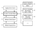
- Prior art medical imaging apparatus typically comprises an imaging control system 1, a hardware control system 2, and a medical imaging device 3 that interacts with the object to be imaged.
- the imaging control system 1 usually includes a user interface and control modules for defining an imaging procedure characterized by image acquisition parameters and commands configured for implementing the imaging procedure by means of the medical imaging device 3.
- the imaging control system 1 controls the hardware control system 2 and communicates to the latter the image acquisition parameters/commands for performing the imaging.
- the hardware control system 2 provides and receives information from the medical imaging device 3 in order to execute the imaging procedure defined by the image acquisition parameters/commands provided by the imaging control system 1.
- the present invention introduces to this known working schema a new transparent layer that is the DCM 4 which is configured for interacting at least with the imaging control system 1 and the hardware control system 2 for optimizing the imaging procedure.
- a set of image acquisition parameters/commands is in particular related to the "field of view” (FOV), for example the image acquisition parameters of said set are geometric information (position and orientation) of the volume to be imaged (e.g. a part of the object to be imaged). If the examined object or at least one part of said object moves during the imaging procedure, the previously defined FOV is rendered invalid with respect to the original planning. Special devices or software modules known in the art might be used for detecting object motion, monitoring the object part under examination and updating accordingly the geometric information. Dynamic change data characterizing the detected motion of the object or of a part of the object, e.g.
- an object motion trajectory is then transferred to the DCM by said special device or software module configured for detecting the object motion and with which the DCM might communicate.
- the dynamic change data comprises updated geometric information related to the FOV related to the detected motion of the imaged object.
- the DCM is then capable of determining new image acquisition parameters/commands related to the FOV from said dynamic change data, the new image acquisition parameters/commands allowing to move the FOV of the imaging procedure so that, for example, the FOV is moved according to the measured object motion trajectory, effectively "following" the object or object part's movement with the FOV.
- the newly determined image acquisition parameters/commands that will optimize the imaging procedure according to the object/object part motion are configured for adapting a rotation matrix defining the gradient coordinate system as well as adapting frequency and phase associated with excitation and demodulation imaging procedures.
- the new image acquisition parameters/commands are transferred or sent by the DCM 4 to the hardware control system 2 which performs the image acquisition based on the new image acquisition parameters/commands which have been optimized by the DCM 4 for the currently object/object part motion.
- the previously described method happens during the acquisition process of the image by the medical imaging apparatus, i.e. in real-time.
- the DCM 4 is transparent for both the image control system 1 and the hardware control system 2, in that none of them has to be changed to implement the motion correction previously described.
- the DCM 4 is transparent to the parts of the imaging control system 1 previously defining the image acquisition parameters/commands as well as the parts of the imaging control system 1 controlling the hardware control system 2.
- the DCM 4 is able to determine new acquisition parameters/commands configured for adapting the MRI apparatus scanner's centre frequency in order to correct frequency drifts caused by technical effects or physiological activity of the imaged object part (e.g. respiration or heart beat).
- an acquisition parameter might be the scanner frequency, which might be in particular regularly measured by a special device or software module.
- Information about the measured scanner frequency might be then fed into the DCM 4 as dynamic change data.
- the DCM 4 could comprise an optimization model correlating the measured scanner frequencies (i.e. the dynamic change data) and the acquisition parameters/commands in order to determine new acquisition parameters/commands that will adapt/correct the imaging procedure for mitigating the effects of frequency drift.
- the image control parameters/commands can be changed transparent to the imaging and hardware control modules or software layers.
- the model provides the information to relate measured frequency drifts to the corrections of the imaging parameters/commands needed to compensate those drifts.
- the DCM 4 comprises at least one interface for another software or hardware module configured for receiving dynamic change data from said software or hardware module, which might be for example a motion correction camera, and/or physiological sensors 52 like a respiration belt, and/or other sensors measuring technical dynamic effects 51 like magnetometers, and/or software modules measuring dynamic effects 53, for example software modules capable of processing specific "navigator" data acquired by the medical imaging device 3 for obtaining dynamic change data, i.e. information about a dynamic effect.
- a motion correction camera and/or physiological sensors 52 like a respiration belt
- other sensors measuring technical dynamic effects 51 like magnetometers
- software modules measuring dynamic effects 53 for example software modules capable of processing specific "navigator" data acquired by the medical imaging device 3 for obtaining dynamic change data, i.e. information about a dynamic effect.
- the DCM 4 is configured for collecting and processing the dynamic change data provided by the above-mentioned sources of dynamic change data, for example by using an optimization model relating the received dynamic change data to the new image acquisition parameters/ commands in order to correct/adapt the image acquisition parameters/commands (e.g. hardware commands) received from the imaging control system 1 and to send to the hardware control system 2 optimized image acquisition parameters/commands, i.e. said new image acquisition parameters/commands determined in real time by the DCM 4 in function of the dynamic change data.
- an optimization model relating the received dynamic change data to the new image acquisition parameters/ commands in order to correct/adapt the image acquisition parameters/commands (e.g. hardware commands) received from the imaging control system 1 and to send to the hardware control system 2 optimized image acquisition parameters/commands, i.e. said new image acquisition parameters/commands determined in real time by the DCM 4 in function of the dynamic change data.
- the DCM 4 according to the invention might be specifically configured for correcting a single dynamic effect, another DCM 4 according to the invention being specifically dedicated to the correction of another single dynamic effect.
- Each DCM 4 correcting a specific dynamic effect might be replaced by another DCM 4 for correcting another specific dynamic effect or might be used together with said another DCM so that two specific dynamic effects might be corrected.
- a single DCM might also correct several specific dynamic effects.
- several DCMs might be concatenated, each of the DCMs either compensating a part of a certain effect or each DCMs correcting a distinct effect.
- the DCM 4 is configured for centralizing all dynamic change data related to dynamic effects that might deteriorate the image quality in order to dynamically correct acquisition parameters/commands by calculating/determining new acquisition parameters/commands. Due to said centralization, the DCM 4 is in particular able to combine information from different input sources, i.e. to combine dynamic change data acquired through different sources (e.g. a camera and another software module). Advantageously, combining information from different sources allows optimizing the correction of the imaging procedure for a specific, in particular single, dynamic effect. Indeed, complementary information might be found from the different sources.
- each communication between the imaging control system 1 and the hardware control system 2 which are free of data related to a dynamic effect is bypassed by the DCM 4.
Landscapes
- Engineering & Computer Science (AREA)
- Physics & Mathematics (AREA)
- General Physics & Mathematics (AREA)
- Signal Processing (AREA)
- Multimedia (AREA)
- Theoretical Computer Science (AREA)
- Computer Vision & Pattern Recognition (AREA)
- Health & Medical Sciences (AREA)
- Radiology & Medical Imaging (AREA)
- Nuclear Medicine, Radiotherapy & Molecular Imaging (AREA)
- General Health & Medical Sciences (AREA)
- High Energy & Nuclear Physics (AREA)
- Condensed Matter Physics & Semiconductors (AREA)
- Medical Informatics (AREA)
- Quality & Reliability (AREA)
- Human Computer Interaction (AREA)
- Magnetic Resonance Imaging Apparatus (AREA)
Abstract
a. connecting a Dynamic Correction Module (hereafter DCM) to the medical imaging apparatus;
b. automatically acquiring by the DCM image acquisition parameters/commands and data about dynamic changes or effects;
c. automatically determining in real time, by means of the DCM, at least one new image acquisition parameter/command from the image acquisition parameters/commands defined in the imaging control system and the dynamic change data, while the image acquisition parameter/command defined in the imaging control system remains unchanged;
d. automatically providing, by means of the DCM, the new image acquisition parameter/command to the hardware control system.
Description
- The present invention relates generally to the correction of artefacts appearing in images obtained by a medical imaging apparatus and coming from dynamic effects occurring during imaging of an object by said medical imaging apparatus.
- It is well known by people skilled in the art that the effect of object motion when imaging an object by means for example of MRI techniques is a common problem which frequently degrades the quality of the MRI image of said object. It can be motion of the object itself or motion of a part, e.g. an internal part, of said object. More generally, effects changing the environment during the imaging process of an object to be imaged, like object motion or changes in the technical environment, are referred to as "dynamic effects". Said dynamic effects have the disadvantage of degrading the image quality of the resulting images notably by creating image artefacts, which might hamper clinical diagnosis or yield the need for rescanning the object, thus increasing healthcare costs and impeding patient comfort.
- Several means to correct dynamic effects exist, aiming at mitigating the resulting image artefacts. Some of the techniques try to improve the images a posteriori (retrospectively), others try to change imaging parameters as, for example, the field-of-view (FOV) already during the medical image acquisition. Retrospective techniques which try to correct data impeded by said effects after they were acquired have the advantage to have minimal or no impact on the imaging process itself, but are unfortunately limited since some artefacts are not correctable a posteriori. Prospective correction methods, on the other hand, can adapt imaging parameters dynamically during the acquisition. They typically require, however, considerable changes in the medical imaging control software or hardware.
- An objective of the present invention is to provide a method and a device for automatically and dynamically optimizing image acquisition parameters and/or image acquisition commands (hereafter "image acquisition parameters / commands" - more generally, "x/y" means in the present patent application "x and/or y") of an imaging procedure performed by a medical imaging apparatus in order to mitigate artefacts resulting from dynamic effects occurring during image acquisition.
- This objective is achieved according to the present invention with respect to a method, in particular a computer-implemented method, for automatically and dynamically optimizing image acquisition parameters and/or image acquisition commands of an imaging procedure performed by a medical imaging apparatus, e.g. a Magnetic Resonance Imaging (MRI) apparatus, in order to mitigate or cancel dynamic effects perturbing the image acquisition process of an object (or subject) to be imaged by said medical imaging apparatus, the latter comprising an imaging control system, a hardware control system and a medical imaging device, the imaging control system being configured for communicating to the hardware control system image acquisition parameters, the hardware control system controlling the medical imaging device according to said image acquisition parameters for performing the imaging procedure, the method according to the invention comprising:
- a. connecting a Dynamic Correction Module (hereafter DCM) to the medical imaging apparatus, for example by using connectors and/or a logical connection, said medical imaging apparatus being preferentially a MRI apparatus configured for acquiring imaging raw data of the object according to a MRI procedure, wherein the DCM might comprise a software and/or a hardware component. Preferentially, the connection of the DCM to the medical imaging apparatus is a logical connection, wherein the DCM is for example a software that comprises programming instructions for enabling the DCM to acquire/collect/send/receive data from the medical imaging apparatus, e.g. from a processing unit of the medical imaging apparatus, and/or from a memory, and/or from an Analog-to-Digital converter, and/or from another software of the medical imaging apparatus, the method according to the invention being in this case preferentially a computer implemented method;
- b. automatically acquiring/collecting by the DCM through its connection to the medical imaging apparatus image acquisition parameters and/or commands defined by and in the imaging control system for performing the imaging procedure projected by the medical imaging apparatus for imaging said object, as well as data about dynamic changes or effects (hereafter "dynamic change data"), wherein said image acquisition parameters and image acquisition commands are respectively data and control commands configured for controlling the medical imaging device of the medical imaging apparatus by means of the hardware control system, the image acquisition parameters/commands defining at least one part, in particular the entire, imaging procedure (e.g., in the context of MRI, image acquisition parameters/commands might be related to real-time events like gradient pulse events, RF pulse events, RF acquisition events) and the dynamic change data being data related to the detection or measurement of a dynamic effect that might degrade the quality of the image obtained for said object by means of the medical imaging apparatus, each dynamic change data comprising in particular information about a motion of at least one part of said object (said part of the object defining for example a volume for which the MRI apparatus will measure an activity, e.g. a brain activity for a part or certain volume of said brain), and/or a technical change such as a drift of the magnetic field or a technically induced change of a RF pulse flip angle in case of an MRI apparatus, and/or an environmental change within the examined part or volume or the imaged object itself such as a change in field homogeneity (shim) in case of an MRI apparatus, the dynamic change data being acquired by the DCM from one or more sources, such as a field probe in case of an MR scanner and/or a respiratory belt to monitor a subject's/patient's respiration and/or a motion detection device (e.g. a camera), of the medical imaging apparatus, through said connection to the medical imaging apparatus or through a direct connection to each of said sources, wherein each source is configured for measuring/detecting at least one dynamic effect;
- c. automatically determining or calculating in real time, by means of the DCM, at least one new image acquisition parameter/command from the image acquisition parameters/commands defined in the imaging control system and the dynamic change data, wherein said new image acquisition parameter/command is preferentially one of the image acquisition parameters/commands defined in the imaging control system (called hereafter "the corresponding image acquisition parameter/command"), but optimized for the dynamic change occurring during imaging the object - in other words, it is an adapted/corrected version/value of the image acquisition parameter/command defined in the imaging control system -, while the corresponding image acquisition parameter/command defined in the imaging control system remains unchanged, i.e. while the corresponding image acquisition parameter/command defined or stored in the imaging control system remains free of any optimization/adaptation, notably in function of said dynamic change data;
- d. automatically providing, by means of the DCM, the new image acquisition parameter/command to the hardware control system. Advantageously, image acquisition parameters/commands defined in the imaging control system are thus adapted or corrected in real time by the DCM in function of said dynamic change data before being processed by the hardware control system in order to perform an imaging procedure and to control the medical imaging device according to the new image acquisition parameter/command.
- According to the present invention, the new image acquisition parameter/command is an image acquisition parameter/command defined in the imaging control system and optimized for the dynamic change occurring during imaging the object. The adaptation/change/correction of the image acquisition parameters/commands that define the imaging procedure is, according to the present method, free of any adaptation/change/correction of the image acquisition parameters/commands that are defined in the imaging control system, e.g. in a software or hardware of the imaging control system. The DCM according to the invention is thus capable of adapting, preferentially automatically adapting, the imaging acquisition parameters/commands in real-time in function of the dynamic change data in a manner free of any change in the execution/running of a software or hardware of the imaging control system whose purpose is the execution of the imaging procedure.
- Advantageously, the present invention completely decouples the imaging control module/layer, i.e. the process controlled by programmed instructions of the software or hardware of the imaging control system for defining and controlling the imaging procedure within the imaging control system during imaging acquisition, e.g. a MR sequence in MRI, and the correction/optimization process performed by the DCM, so that it becomes possible to apply the correction/optimization performed by the DCM to any imaging procedure without or with very little additional efforts. Indeed, the DCM according to the invention comprises in particular several optimization procedures/models for optimizing image acquisition parameters/commands in function of dynamic changes reported by the dynamic change data. Indeed, the DCM according to the invention may comprise in particular a memory for storing one or several models, each designed for mitigating the effect of a specific dynamic change during image acquisition, e.g. the motion of the object during image acquisition, by determining said new image acquisition parameters/commands and adapting in real time the imaging procedure of the medical imaging apparatus to the new image acquisition parameters/commands.
- The present invention also concerns a DCM configured for optimizing in real time image acquisition parameters/commands of an imaging procedure performed by a medical imaging apparatus for imaging an object, the DCM comprising:
- connectors for connecting, e.g. logically and/or physically connecting, the DCM to the medical imaging apparatus, for example the connectors are logical connectors and the DCM is a software and/or comprises programming instructions stored in a memory;
- a processing unit for processing dynamic change data and image acquisition parameters/commands;
- a computer readable medium comprising a memory for storing computer executable instructions, that, when executed, cause the processing unit to perform steps b-d previously described, said computer executable instructions comprising at least one, preferentially several optimization procedures for optimizing the image acquisition parameters/commands in function of dynamic changes occurring in real time during imaging of said object by means of the medical imaging apparatus, wherein preferentially each optimization procedure is configured for mitigating one or several dynamic effects.
- Finally, the present invention also concerns a MRI apparatus for imaging an object, said MRI apparatus comprising the DCM.
- The present invention proposes thus a method and a device, the so-called DCM, that is configured for cooperating with a medical imaging apparatus like a MRI apparatus in order to correct for dynamic effects occurring during a medical imaging exam and that may impede the resulting image quality. The present invention advantageously facilitates the implementation of correction methods for different perturbing dynamic effects like motion, hardware-induced environment changes, physiological changes, etc., in a single device, i.e. said DCM, that has a unified interface for cooperating with the medical imaging device and with other devices providing said dynamic change data. Compared to prior art techniques, the present invention also avoids the requirement of separate correction of the dynamics effects, since they can all be corrected in a single step by means of the present invention.
- The claimed invention will be best understood from the following detailed description of specific embodiments when read in connection with the accompanying drawings:
- Figure 1
- schematic illustration of the claimed method.
- The present invention will be described now by taking two specific examples of dynamic changes, respectively motion and frequency drift occurring during an examination in an MRI apparatus, in relation with Figure 1. The two specific examples only serve as illustration of the present invention. The skilled man will recognize that the present invention applies to other dynamic changes in a similar way.
- Prior art medical imaging apparatus typically comprises an imaging control system 1, a
hardware control system 2, and amedical imaging device 3 that interacts with the object to be imaged. The imaging control system 1 usually includes a user interface and control modules for defining an imaging procedure characterized by image acquisition parameters and commands configured for implementing the imaging procedure by means of themedical imaging device 3. The imaging control system 1 controls thehardware control system 2 and communicates to the latter the image acquisition parameters/commands for performing the imaging. Thehardware control system 2 provides and receives information from themedical imaging device 3 in order to execute the imaging procedure defined by the image acquisition parameters/commands provided by the imaging control system 1. The present invention introduces to this known working schema a new transparent layer that is theDCM 4 which is configured for interacting at least with the imaging control system 1 and thehardware control system 2 for optimizing the imaging procedure. - In case of motion correction, a set of image acquisition parameters/commands is in particular related to the "field of view" (FOV), for example the image acquisition parameters of said set are geometric information (position and orientation) of the volume to be imaged (e.g. a part of the object to be imaged). If the examined object or at least one part of said object moves during the imaging procedure, the previously defined FOV is rendered invalid with respect to the original planning. Special devices or software modules known in the art might be used for detecting object motion, monitoring the object part under examination and updating accordingly the geometric information. Dynamic change data characterizing the detected motion of the object or of a part of the object, e.g. an object motion trajectory, is then transferred to the DCM by said special device or software module configured for detecting the object motion and with which the DCM might communicate. In this particular case, the dynamic change data comprises updated geometric information related to the FOV related to the detected motion of the imaged object. After reception of the dynamic change data, the DCM is then capable of determining new image acquisition parameters/commands related to the FOV from said dynamic change data, the new image acquisition parameters/commands allowing to move the FOV of the imaging procedure so that, for example, the FOV is moved according to the measured object motion trajectory, effectively "following" the object or object part's movement with the FOV. In particular, if the medical imaging apparatus is a MRI apparatus, the newly determined image acquisition parameters/commands that will optimize the imaging procedure according to the object/object part motion are configured for adapting a rotation matrix defining the gradient coordinate system as well as adapting frequency and phase associated with excitation and demodulation imaging procedures. Finally, the new image acquisition parameters/commands are transferred or sent by the
DCM 4 to thehardware control system 2 which performs the image acquisition based on the new image acquisition parameters/commands which have been optimized by theDCM 4 for the currently object/object part motion. The previously described method happens during the acquisition process of the image by the medical imaging apparatus, i.e. in real-time. - Advantageously, the
DCM 4 is transparent for both the image control system 1 and thehardware control system 2, in that none of them has to be changed to implement the motion correction previously described. In other words, theDCM 4 is transparent to the parts of the imaging control system 1 previously defining the image acquisition parameters/commands as well as the parts of the imaging control system 1 controlling thehardware control system 2. - In case of frequency drift correction in an MRI apparatus, the
DCM 4 is able to determine new acquisition parameters/commands configured for adapting the MRI apparatus scanner's centre frequency in order to correct frequency drifts caused by technical effects or physiological activity of the imaged object part (e.g. respiration or heart beat). In this case, an acquisition parameter might be the scanner frequency, which might be in particular regularly measured by a special device or software module. Information about the measured scanner frequency might be then fed into theDCM 4 as dynamic change data. According to the present invention, theDCM 4 could comprise an optimization model correlating the measured scanner frequencies (i.e. the dynamic change data) and the acquisition parameters/commands in order to determine new acquisition parameters/commands that will adapt/correct the imaging procedure for mitigating the effects of frequency drift. Again, by using a DCM augmented by a model, the image control parameters/commands can be changed transparent to the imaging and hardware control modules or software layers. Hereby the model provides the information to relate measured frequency drifts to the corrections of the imaging parameters/commands needed to compensate those drifts. - In particular, the
DCM 4 according to the present invention comprises at least one interface for another software or hardware module configured for receiving dynamic change data from said software or hardware module, which might be for example a motion correction camera, and/orphysiological sensors 52 like a respiration belt, and/or other sensors measuring technicaldynamic effects 51 like magnetometers, and/or software modules measuringdynamic effects 53, for example software modules capable of processing specific "navigator" data acquired by themedical imaging device 3 for obtaining dynamic change data, i.e. information about a dynamic effect. TheDCM 4 is configured for collecting and processing the dynamic change data provided by the above-mentioned sources of dynamic change data, for example by using an optimization model relating the received dynamic change data to the new image acquisition parameters/ commands in order to correct/adapt the image acquisition parameters/commands (e.g. hardware commands) received from the imaging control system 1 and to send to thehardware control system 2 optimized image acquisition parameters/commands, i.e. said new image acquisition parameters/commands determined in real time by theDCM 4 in function of the dynamic change data. - Advantageously, the
DCM 4 according to the invention might be specifically configured for correcting a single dynamic effect, anotherDCM 4 according to the invention being specifically dedicated to the correction of another single dynamic effect. EachDCM 4 correcting a specific dynamic effect might be replaced by anotherDCM 4 for correcting another specific dynamic effect or might be used together with said another DCM so that two specific dynamic effects might be corrected. A single DCM might also correct several specific dynamic effects. In particular, several DCMs might be concatenated, each of the DCMs either compensating a part of a certain effect or each DCMs correcting a distinct effect. - According to the present invention, the
DCM 4 is configured for centralizing all dynamic change data related to dynamic effects that might deteriorate the image quality in order to dynamically correct acquisition parameters/commands by calculating/determining new acquisition parameters/commands. Due to said centralization, theDCM 4 is in particular able to combine information from different input sources, i.e. to combine dynamic change data acquired through different sources (e.g. a camera and another software module). Advantageously, combining information from different sources allows optimizing the correction of the imaging procedure for a specific, in particular single, dynamic effect. Indeed, complementary information might be found from the different sources. - Preferentially, each communication between the imaging control system 1 and the
hardware control system 2 which are free of data related to a dynamic effect is bypassed by theDCM 4.
Claims (13)
- A method for automatically and dynamically optimizing image acquisition parameters/commands of an imaging procedure performed by a medical imaging apparatus in order to mitigate or cancel dynamic effects perturbing the image acquisition process of an object to be imaged by said medical imaging apparatus, the method comprising:a. connecting a Dynamic Correction Module (hereafter DCM) (4) to the medical imaging apparatus;b. automatically acquiring by the DCM (4)- data about dynamic changes or effects (hereafter "dynamic change data"); and- image acquisition parameters/commands defined by an imaging control system (1) of the medical imaging apparatus;c. automatically determining in real time, by means of the DCM (4), at least one new image acquisition parameter/command from the dynamic change data and the image acquisition parameters/commands defined in the imaging control system (1), the image acquisition parameters/commands defined in the imaging control system remaining free of any adaptation to the dynamic change data;d. automatically providing, by means of the DCM, the new image acquisition parameter/command to the hardware control system.
- Method according to claim 1, wherein the dynamic change data are data related to the detection or measurement of a dynamic effect that might degrade the quality of the image obtained for said object by means of the medical imaging apparatus.
- Method according to claim 1 or 2, wherein each dynamic change data comprises information about a motion of at least one part of said object, and/or a technical change of the medical imaging apparatus or parts of it, and/or an environmental change of the imaged volume or the imaged object/subject.
- Method according to one of the claims 1 to 3, wherein the dynamic change data are acquired by the DCM (4) from one or more sources of the medical imaging apparatus, wherein each source is configured for measuring/detecting at least one dynamic effect.
- Method according to claim 4, wherein the DCM (4) is configured for combining dynamic change data of at least two sources for optimizing the correction of the imaging procedure for a single dynamic effect.
- Method according to one of the claims 1 to 5, wherein the image acquisition parameters/commands are defined by an imaging control system (1) of the medical imaging apparatus for performing the imaging procedure projected by the medical imaging apparatus for imaging said object.
- Method according to one of the previous claims, wherein the image acquisition parameters/commands define at least one part of the imaging procedure.
- Method according to one of the previous claims, wherein the image acquisition parameters/commands are data/control commands configured for controlling a medical imaging device (3) of the medical imaging apparatus by means of a hardware control system (2).
- Method according to one of the previous claims, wherein the medical imaging apparatus is a Magnetic Resonance Imaging apparatus and the image acquisition parameters/commands are data/commands about a gradient pulse, and/or a radio frequency pulse, and/or a radio frequency data sampling.
- Dynamic Correction Module (hereafter DCM) (4) for optimizing in real-time image acquisition parameters/commands of an imaging procedure performed by a medical imaging apparatus for imaging an object, the DCM (4) comprising:- connections means for connecting the DCM (4) to the medical imaging apparatus;- a processing unit for processing dynamic change data and image acquisition parameters/commands;- a computer readable medium comprising a memory for storing computer executable instructions, that, when executed, cause the processing unit to perform steps (b) to (d) of one of the claims 1-8.
- DCM (4) according to claim 10, wherein the computer executable instructions comprise several optimization procedures/models for optimizing the image acquisition parameters/commands in function of dynamic changes occurring in real-time during imaging of said object by means of the medical imaging apparatus, wherein each optimization procedure is configured for mitigating one dynamic effect.
- DCM (4) according to claim 10 or 11, configured for combining the dynamic change data acquired from one or more different sources of the medical imaging apparatus, wherein each source is configured for measuring/detecting at least one dynamic effect, the DCM (4) being further configured for combining the dynamic change data of at least two sources for optimizing the correction of the imaging procedure for a single dynamic effect.
- Magnetic Resonance Imaging apparatus for imaging an object, said Magnetic Resonance Imaging apparatus comprising the DCM (4) according to one of the claims 10 to 12.
Priority Applications (2)
| Application Number | Priority Date | Filing Date | Title |
|---|---|---|---|
| EP15162610.8A EP3078980B1 (en) | 2015-04-07 | 2015-04-07 | Dynamic effects correction in medical imaging |
| US15/092,843 US10275875B2 (en) | 2015-04-07 | 2016-04-07 | Method and device for dynamic effects correction in medical imaging |
Applications Claiming Priority (1)
| Application Number | Priority Date | Filing Date | Title |
|---|---|---|---|
| EP15162610.8A EP3078980B1 (en) | 2015-04-07 | 2015-04-07 | Dynamic effects correction in medical imaging |
Publications (2)
| Publication Number | Publication Date |
|---|---|
| EP3078980A1 true EP3078980A1 (en) | 2016-10-12 |
| EP3078980B1 EP3078980B1 (en) | 2020-06-17 |
Family
ID=52997842
Family Applications (1)
| Application Number | Title | Priority Date | Filing Date |
|---|---|---|---|
| EP15162610.8A Active EP3078980B1 (en) | 2015-04-07 | 2015-04-07 | Dynamic effects correction in medical imaging |
Country Status (2)
| Country | Link |
|---|---|
| US (1) | US10275875B2 (en) |
| EP (1) | EP3078980B1 (en) |
Families Citing this family (1)
| Publication number | Priority date | Publication date | Assignee | Title |
|---|---|---|---|---|
| US11249162B1 (en) | 2020-08-04 | 2022-02-15 | Siemens Healthcare Gmbh | Motion corrected blipped CAIPIRINHA and SMS |
Citations (3)
| Publication number | Priority date | Publication date | Assignee | Title |
|---|---|---|---|---|
| WO2007106360A1 (en) * | 2006-03-10 | 2007-09-20 | The Government Of The United States Of America, As Represented By The Secretary, Department Of Health And Human Services | Real-time shimming of respiration induced polarizing magnetic field changes |
| US20090209846A1 (en) * | 2006-06-28 | 2009-08-20 | Roland Bammer | Apparatus and method for real-time motion-compensated magnetic resonance imaging |
| US20120268124A1 (en) * | 2011-04-18 | 2012-10-25 | Michael Herbst | Method for quasi-continous dynamic motion correciton in magnetic resonance measurements |
Family Cites Families (7)
| Publication number | Priority date | Publication date | Assignee | Title |
|---|---|---|---|---|
| AU2001253160A1 (en) * | 2000-05-04 | 2001-11-12 | Mayo Foundation For Medical Education And Research | Prospective multi-planar motion correction in mri |
| DE10330926B4 (en) * | 2003-07-08 | 2008-11-27 | Siemens Ag | Method for the absolute correction of B0 field deviations in magnetic resonance tomography imaging |
| DE102004004603A1 (en) * | 2004-01-29 | 2005-08-18 | Siemens Ag | Medical imaging patient movement compensation procedure registers first image with known calibration and compares subsequent images to determine differences for compensation |
| CN101238391B (en) * | 2005-08-04 | 2012-08-29 | 皇家飞利浦电子股份有限公司 | Motion compensation in functional imaging |
| US8191359B2 (en) * | 2006-04-13 | 2012-06-05 | The Regents Of The University Of California | Motion estimation using hidden markov model processing in MRI and other applications |
| JP5539712B2 (en) * | 2006-04-20 | 2014-07-02 | コーニンクレッカ フィリップス エヌ ヴェ | Motion compensation method for dynamic volume alignment without timing limitation |
| EP2023812B1 (en) * | 2006-05-19 | 2016-01-27 | The Queen's Medical Center | Motion tracking system for real time adaptive imaging and spectroscopy |
-
2015
- 2015-04-07 EP EP15162610.8A patent/EP3078980B1/en active Active
-
2016
- 2016-04-07 US US15/092,843 patent/US10275875B2/en active Active
Patent Citations (3)
| Publication number | Priority date | Publication date | Assignee | Title |
|---|---|---|---|---|
| WO2007106360A1 (en) * | 2006-03-10 | 2007-09-20 | The Government Of The United States Of America, As Represented By The Secretary, Department Of Health And Human Services | Real-time shimming of respiration induced polarizing magnetic field changes |
| US20090209846A1 (en) * | 2006-06-28 | 2009-08-20 | Roland Bammer | Apparatus and method for real-time motion-compensated magnetic resonance imaging |
| US20120268124A1 (en) * | 2011-04-18 | 2012-10-25 | Michael Herbst | Method for quasi-continous dynamic motion correciton in magnetic resonance measurements |
Non-Patent Citations (5)
| Title |
|---|
| DOLD C ET AL: "Advantages and Limitations of Prospective Head Motion Compensation for MRI Using an Optical Motion Tracking Device", ACADEMIC RADIOLOGY, RESTON, VA, US, vol. 13, no. 9, 1 September 2006 (2006-09-01), pages 1093 - 1103, XP028012632, ISSN: 1076-6332, [retrieved on 20060901], DOI: 10.1016/J.ACRA.2006.05.010 * |
| MURAT AKSOY ET AL: "Real-time optical motion correction for diffusion tensor imaging", MAGNETIC RESONANCE IN MEDICINE, vol. 66, no. 2, 22 March 2011 (2011-03-22), pages 366 - 378, XP055031759, ISSN: 0740-3194, DOI: 10.1002/mrm.22787 * |
| SANTOS J M ET AL: "Flexible real-time magnetic resonance imaging framework", PROCEEDINGS OF THE 26TH ANNUAL INTERNATIONAL CONFERENCE OF THE IEEE EMBS SAN FRANCISCO,CA, EMBS SAN FRANCISCO, CA, USA, vol. 3, 1 September 2004 (2004-09-01), pages 1048 - 1051, XP010774954, ISBN: 978-0-7803-8439-2, DOI: 10.1109/IEMBS.2004.1403343 * |
| WHITE N ET AL: "PROMO: Real-time prospective motion correction in MRI using image-based tracking", MAGNETIC RESONANCE IN MEDICINE, JOHN WILEY & SONS, INC, US, vol. 63, no. 1, 1 January 2010 (2010-01-01), pages 91 - 105, XP007916079, ISSN: 0740-3194, [retrieved on 20091221] * |
| ZAITSEV M ET AL: "Magnetic resonance imaging of freely moving objects: prospective real-time motion correction using an external optical motion tracking system", NEUROIMAGE, ACADEMIC PRESS, ORLANDO, FL, US, vol. 31, no. 3, 1 July 2006 (2006-07-01), pages 1038 - 1050, XP024906396, ISSN: 1053-8119, [retrieved on 20060701], DOI: 10.1016/J.NEUROIMAGE.2006.01.039 * |
Also Published As
| Publication number | Publication date |
|---|---|
| US10275875B2 (en) | 2019-04-30 |
| EP3078980B1 (en) | 2020-06-17 |
| US20160300353A1 (en) | 2016-10-13 |
Similar Documents
| Publication | Publication Date | Title |
|---|---|---|
| US10185018B2 (en) | Method for motion correction in magnetic resonance imaging and magnetic resonance imaging apparatus | |
| US10869611B2 (en) | Motion tracking system for real time adaptive imaging and spectroscopy | |
| US20140073904A1 (en) | Method for acquiring a movement of a patient during a medical imaging examination | |
| JP5178521B2 (en) | System and method for acquiring magnetic resonance imaging (MRI) data | |
| US8195417B2 (en) | Method for recording measured data from a patient by taking movements into account, and associated medical device | |
| CN111007447A (en) | False detection motion detection | |
| US20140077811A1 (en) | Wireless prospective motion marker | |
| US10191131B2 (en) | Medical imaging apparatus having multiple subsystems, and operating method therefor | |
| US10168407B2 (en) | Medical imaging apparatus having multiple subsystems, and operating method therefor | |
| CN108366755B (en) | Scanning and tracking monitoring device and method | |
| US20030144589A1 (en) | Method for operating a medical imaging diagnostic apparatus | |
| US12347142B2 (en) | Tomographic imaging with motion detection system | |
| US10036795B2 (en) | Method for the adjustment of at least one magnetic resonance image data set of a movable examination object and correspondingly designed magnetic resonance device | |
| EP3078980B1 (en) | Dynamic effects correction in medical imaging | |
| US20170061615A1 (en) | Image identification method, magnetic resonance imaging method and imaging apparatus | |
| JP7668115B2 (en) | Magnetic resonance imaging device and program | |
| US20260090739A1 (en) | Medical imaging apparatus and body movement data processing method | |
| CN104224176B (en) | For the magnetic resonance examination method that matching layer is positioned in layer protocol and magnetic resonance equipment | |
| EP3901649A1 (en) | Arrangement and method for motion correction in magnetic resonance imaging | |
| JP2013111274A (en) | Slice position setting device, magnetic resonance apparatus, slice position setting method, and program | |
| JP2013132333A (en) | Magnetic resonance apparatus and program |
Legal Events
| Date | Code | Title | Description |
|---|---|---|---|
| PUAI | Public reference made under article 153(3) epc to a published international application that has entered the european phase |
Free format text: ORIGINAL CODE: 0009012 |
|
| AK | Designated contracting states |
Kind code of ref document: A1 Designated state(s): AL AT BE BG CH CY CZ DE DK EE ES FI FR GB GR HR HU IE IS IT LI LT LU LV MC MK MT NL NO PL PT RO RS SE SI SK SM TR |
|
| AX | Request for extension of the european patent |
Extension state: BA ME |
|
| STAA | Information on the status of an ep patent application or granted ep patent |
Free format text: STATUS: REQUEST FOR EXAMINATION WAS MADE |
|
| 17P | Request for examination filed |
Effective date: 20170306 |
|
| RBV | Designated contracting states (corrected) |
Designated state(s): AL AT BE BG CH CY CZ DE DK EE ES FI FR GB GR HR HU IE IS IT LI LT LU LV MC MK MT NL NO PL PT RO RS SE SI SK SM TR |
|
| GRAP | Despatch of communication of intention to grant a patent |
Free format text: ORIGINAL CODE: EPIDOSNIGR1 |
|
| STAA | Information on the status of an ep patent application or granted ep patent |
Free format text: STATUS: GRANT OF PATENT IS INTENDED |
|
| INTG | Intention to grant announced |
Effective date: 20200312 |
|
| GRAS | Grant fee paid |
Free format text: ORIGINAL CODE: EPIDOSNIGR3 |
|
| GRAA | (expected) grant |
Free format text: ORIGINAL CODE: 0009210 |
|
| STAA | Information on the status of an ep patent application or granted ep patent |
Free format text: STATUS: THE PATENT HAS BEEN GRANTED |
|
| AK | Designated contracting states |
Kind code of ref document: B1 Designated state(s): AL AT BE BG CH CY CZ DE DK EE ES FI FR GB GR HR HU IE IS IT LI LT LU LV MC MK MT NL NO PL PT RO RS SE SI SK SM TR |
|
| REG | Reference to a national code |
Ref country code: GB Ref legal event code: FG4D |
|
| REG | Reference to a national code |
Ref country code: CH Ref legal event code: EP |
|
| REG | Reference to a national code |
Ref country code: IE Ref legal event code: FG4D |
|
| REG | Reference to a national code |
Ref country code: DE Ref legal event code: R096 Ref document number: 602015054253 Country of ref document: DE |
|
| REG | Reference to a national code |
Ref country code: AT Ref legal event code: REF Ref document number: 1281987 Country of ref document: AT Kind code of ref document: T Effective date: 20200715 |
|
| PG25 | Lapsed in a contracting state [announced via postgrant information from national office to epo] |
Ref country code: SE Free format text: LAPSE BECAUSE OF FAILURE TO SUBMIT A TRANSLATION OF THE DESCRIPTION OR TO PAY THE FEE WITHIN THE PRESCRIBED TIME-LIMIT Effective date: 20200617 Ref country code: NO Free format text: LAPSE BECAUSE OF FAILURE TO SUBMIT A TRANSLATION OF THE DESCRIPTION OR TO PAY THE FEE WITHIN THE PRESCRIBED TIME-LIMIT Effective date: 20200917 Ref country code: FI Free format text: LAPSE BECAUSE OF FAILURE TO SUBMIT A TRANSLATION OF THE DESCRIPTION OR TO PAY THE FEE WITHIN THE PRESCRIBED TIME-LIMIT Effective date: 20200617 Ref country code: GR Free format text: LAPSE BECAUSE OF FAILURE TO SUBMIT A TRANSLATION OF THE DESCRIPTION OR TO PAY THE FEE WITHIN THE PRESCRIBED TIME-LIMIT Effective date: 20200918 Ref country code: LT Free format text: LAPSE BECAUSE OF FAILURE TO SUBMIT A TRANSLATION OF THE DESCRIPTION OR TO PAY THE FEE WITHIN THE PRESCRIBED TIME-LIMIT Effective date: 20200617 |
|
| REG | Reference to a national code |
Ref country code: LT Ref legal event code: MG4D |
|
| REG | Reference to a national code |
Ref country code: NL Ref legal event code: MP Effective date: 20200617 |
|
| PG25 | Lapsed in a contracting state [announced via postgrant information from national office to epo] |
Ref country code: LV Free format text: LAPSE BECAUSE OF FAILURE TO SUBMIT A TRANSLATION OF THE DESCRIPTION OR TO PAY THE FEE WITHIN THE PRESCRIBED TIME-LIMIT Effective date: 20200617 Ref country code: HR Free format text: LAPSE BECAUSE OF FAILURE TO SUBMIT A TRANSLATION OF THE DESCRIPTION OR TO PAY THE FEE WITHIN THE PRESCRIBED TIME-LIMIT Effective date: 20200617 Ref country code: BG Free format text: LAPSE BECAUSE OF FAILURE TO SUBMIT A TRANSLATION OF THE DESCRIPTION OR TO PAY THE FEE WITHIN THE PRESCRIBED TIME-LIMIT Effective date: 20200917 Ref country code: RS Free format text: LAPSE BECAUSE OF FAILURE TO SUBMIT A TRANSLATION OF THE DESCRIPTION OR TO PAY THE FEE WITHIN THE PRESCRIBED TIME-LIMIT Effective date: 20200617 |
|
| REG | Reference to a national code |
Ref country code: AT Ref legal event code: MK05 Ref document number: 1281987 Country of ref document: AT Kind code of ref document: T Effective date: 20200617 |
|
| PG25 | Lapsed in a contracting state [announced via postgrant information from national office to epo] |
Ref country code: NL Free format text: LAPSE BECAUSE OF FAILURE TO SUBMIT A TRANSLATION OF THE DESCRIPTION OR TO PAY THE FEE WITHIN THE PRESCRIBED TIME-LIMIT Effective date: 20200617 Ref country code: AL Free format text: LAPSE BECAUSE OF FAILURE TO SUBMIT A TRANSLATION OF THE DESCRIPTION OR TO PAY THE FEE WITHIN THE PRESCRIBED TIME-LIMIT Effective date: 20200617 |
|
| PG25 | Lapsed in a contracting state [announced via postgrant information from national office to epo] |
Ref country code: CZ Free format text: LAPSE BECAUSE OF FAILURE TO SUBMIT A TRANSLATION OF THE DESCRIPTION OR TO PAY THE FEE WITHIN THE PRESCRIBED TIME-LIMIT Effective date: 20200617 Ref country code: RO Free format text: LAPSE BECAUSE OF FAILURE TO SUBMIT A TRANSLATION OF THE DESCRIPTION OR TO PAY THE FEE WITHIN THE PRESCRIBED TIME-LIMIT Effective date: 20200617 Ref country code: EE Free format text: LAPSE BECAUSE OF FAILURE TO SUBMIT A TRANSLATION OF THE DESCRIPTION OR TO PAY THE FEE WITHIN THE PRESCRIBED TIME-LIMIT Effective date: 20200617 Ref country code: SM Free format text: LAPSE BECAUSE OF FAILURE TO SUBMIT A TRANSLATION OF THE DESCRIPTION OR TO PAY THE FEE WITHIN THE PRESCRIBED TIME-LIMIT Effective date: 20200617 Ref country code: IT Free format text: LAPSE BECAUSE OF FAILURE TO SUBMIT A TRANSLATION OF THE DESCRIPTION OR TO PAY THE FEE WITHIN THE PRESCRIBED TIME-LIMIT Effective date: 20200617 Ref country code: AT Free format text: LAPSE BECAUSE OF FAILURE TO SUBMIT A TRANSLATION OF THE DESCRIPTION OR TO PAY THE FEE WITHIN THE PRESCRIBED TIME-LIMIT Effective date: 20200617 Ref country code: PT Free format text: LAPSE BECAUSE OF FAILURE TO SUBMIT A TRANSLATION OF THE DESCRIPTION OR TO PAY THE FEE WITHIN THE PRESCRIBED TIME-LIMIT Effective date: 20201019 Ref country code: ES Free format text: LAPSE BECAUSE OF FAILURE TO SUBMIT A TRANSLATION OF THE DESCRIPTION OR TO PAY THE FEE WITHIN THE PRESCRIBED TIME-LIMIT Effective date: 20200617 |
|
| PG25 | Lapsed in a contracting state [announced via postgrant information from national office to epo] |
Ref country code: SK Free format text: LAPSE BECAUSE OF FAILURE TO SUBMIT A TRANSLATION OF THE DESCRIPTION OR TO PAY THE FEE WITHIN THE PRESCRIBED TIME-LIMIT Effective date: 20200617 Ref country code: PL Free format text: LAPSE BECAUSE OF FAILURE TO SUBMIT A TRANSLATION OF THE DESCRIPTION OR TO PAY THE FEE WITHIN THE PRESCRIBED TIME-LIMIT Effective date: 20200617 Ref country code: IS Free format text: LAPSE BECAUSE OF FAILURE TO SUBMIT A TRANSLATION OF THE DESCRIPTION OR TO PAY THE FEE WITHIN THE PRESCRIBED TIME-LIMIT Effective date: 20201017 |
|
| REG | Reference to a national code |
Ref country code: DE Ref legal event code: R097 Ref document number: 602015054253 Country of ref document: DE |
|
| PLBE | No opposition filed within time limit |
Free format text: ORIGINAL CODE: 0009261 |
|
| STAA | Information on the status of an ep patent application or granted ep patent |
Free format text: STATUS: NO OPPOSITION FILED WITHIN TIME LIMIT |
|
| PG25 | Lapsed in a contracting state [announced via postgrant information from national office to epo] |
Ref country code: DK Free format text: LAPSE BECAUSE OF FAILURE TO SUBMIT A TRANSLATION OF THE DESCRIPTION OR TO PAY THE FEE WITHIN THE PRESCRIBED TIME-LIMIT Effective date: 20200617 |
|
| 26N | No opposition filed |
Effective date: 20210318 |
|
| PG25 | Lapsed in a contracting state [announced via postgrant information from national office to epo] |
Ref country code: SI Free format text: LAPSE BECAUSE OF FAILURE TO SUBMIT A TRANSLATION OF THE DESCRIPTION OR TO PAY THE FEE WITHIN THE PRESCRIBED TIME-LIMIT Effective date: 20200617 |
|
| PG25 | Lapsed in a contracting state [announced via postgrant information from national office to epo] |
Ref country code: MC Free format text: LAPSE BECAUSE OF FAILURE TO SUBMIT A TRANSLATION OF THE DESCRIPTION OR TO PAY THE FEE WITHIN THE PRESCRIBED TIME-LIMIT Effective date: 20200617 |
|
| PG25 | Lapsed in a contracting state [announced via postgrant information from national office to epo] |
Ref country code: LU Free format text: LAPSE BECAUSE OF NON-PAYMENT OF DUE FEES Effective date: 20210407 |
|
| REG | Reference to a national code |
Ref country code: BE Ref legal event code: MM Effective date: 20210430 |
|
| PG25 | Lapsed in a contracting state [announced via postgrant information from national office to epo] |
Ref country code: LI Free format text: LAPSE BECAUSE OF NON-PAYMENT OF DUE FEES Effective date: 20210430 Ref country code: CH Free format text: LAPSE BECAUSE OF NON-PAYMENT OF DUE FEES Effective date: 20210430 |
|
| PG25 | Lapsed in a contracting state [announced via postgrant information from national office to epo] |
Ref country code: IE Free format text: LAPSE BECAUSE OF NON-PAYMENT OF DUE FEES Effective date: 20210407 |
|
| PG25 | Lapsed in a contracting state [announced via postgrant information from national office to epo] |
Ref country code: IS Free format text: LAPSE BECAUSE OF FAILURE TO SUBMIT A TRANSLATION OF THE DESCRIPTION OR TO PAY THE FEE WITHIN THE PRESCRIBED TIME-LIMIT Effective date: 20201017 |
|
| PG25 | Lapsed in a contracting state [announced via postgrant information from national office to epo] |
Ref country code: BE Free format text: LAPSE BECAUSE OF NON-PAYMENT OF DUE FEES Effective date: 20210430 |
|
| PG25 | Lapsed in a contracting state [announced via postgrant information from national office to epo] |
Ref country code: HU Free format text: LAPSE BECAUSE OF FAILURE TO SUBMIT A TRANSLATION OF THE DESCRIPTION OR TO PAY THE FEE WITHIN THE PRESCRIBED TIME-LIMIT; INVALID AB INITIO Effective date: 20150407 |
|
| PG25 | Lapsed in a contracting state [announced via postgrant information from national office to epo] |
Ref country code: CY Free format text: LAPSE BECAUSE OF FAILURE TO SUBMIT A TRANSLATION OF THE DESCRIPTION OR TO PAY THE FEE WITHIN THE PRESCRIBED TIME-LIMIT Effective date: 20200617 |
|
| REG | Reference to a national code |
Ref country code: DE Ref legal event code: R081 Ref document number: 602015054253 Country of ref document: DE Owner name: SIEMENS HEALTHINEERS AG, DE Free format text: FORMER OWNER: SIEMENS HEALTHCARE GMBH, MUENCHEN, DE |
|
| PG25 | Lapsed in a contracting state [announced via postgrant information from national office to epo] |
Ref country code: MK Free format text: LAPSE BECAUSE OF FAILURE TO SUBMIT A TRANSLATION OF THE DESCRIPTION OR TO PAY THE FEE WITHIN THE PRESCRIBED TIME-LIMIT Effective date: 20200617 |
|
| PG25 | Lapsed in a contracting state [announced via postgrant information from national office to epo] |
Ref country code: TR Free format text: LAPSE BECAUSE OF FAILURE TO SUBMIT A TRANSLATION OF THE DESCRIPTION OR TO PAY THE FEE WITHIN THE PRESCRIBED TIME-LIMIT Effective date: 20200617 |
|
| PG25 | Lapsed in a contracting state [announced via postgrant information from national office to epo] |
Ref country code: MT Free format text: LAPSE BECAUSE OF FAILURE TO SUBMIT A TRANSLATION OF THE DESCRIPTION OR TO PAY THE FEE WITHIN THE PRESCRIBED TIME-LIMIT Effective date: 20200617 |
|
| PGFP | Annual fee paid to national office [announced via postgrant information from national office to epo] |
Ref country code: DE Payment date: 20250620 Year of fee payment: 11 |
|
| PGFP | Annual fee paid to national office [announced via postgrant information from national office to epo] |
Ref country code: GB Payment date: 20250507 Year of fee payment: 11 |
|
| PGFP | Annual fee paid to national office [announced via postgrant information from national office to epo] |
Ref country code: FR Payment date: 20250411 Year of fee payment: 11 |
|
| REG | Reference to a national code |
Ref country code: DE Ref legal event code: R082 Ref document number: 602015054253 Country of ref document: DE |