EP3078857B1 - High speed internal gear pump - Google Patents
High speed internal gear pump Download PDFInfo
- Publication number
- EP3078857B1 EP3078857B1 EP16164541.1A EP16164541A EP3078857B1 EP 3078857 B1 EP3078857 B1 EP 3078857B1 EP 16164541 A EP16164541 A EP 16164541A EP 3078857 B1 EP3078857 B1 EP 3078857B1
- Authority
- EP
- European Patent Office
- Prior art keywords
- idler
- crescent
- support
- inlet
- rotor
- Prior art date
- Legal status (The legal status is an assumption and is not a legal conclusion. Google has not performed a legal analysis and makes no representation as to the accuracy of the status listed.)
- Active
Links
Images



Classifications
-
- F—MECHANICAL ENGINEERING; LIGHTING; HEATING; WEAPONS; BLASTING
- F04—POSITIVE - DISPLACEMENT MACHINES FOR LIQUIDS; PUMPS FOR LIQUIDS OR ELASTIC FLUIDS
- F04C—ROTARY-PISTON, OR OSCILLATING-PISTON, POSITIVE-DISPLACEMENT MACHINES FOR LIQUIDS; ROTARY-PISTON, OR OSCILLATING-PISTON, POSITIVE-DISPLACEMENT PUMPS
- F04C2/00—Rotary-piston machines or pumps
- F04C2/08—Rotary-piston machines or pumps of intermeshing-engagement type, i.e. with engagement of co-operating members similar to that of toothed gearing
- F04C2/082—Details specially related to intermeshing engagement type machines or pumps
- F04C2/084—Toothed wheels
-
- F—MECHANICAL ENGINEERING; LIGHTING; HEATING; WEAPONS; BLASTING
- F04—POSITIVE - DISPLACEMENT MACHINES FOR LIQUIDS; PUMPS FOR LIQUIDS OR ELASTIC FLUIDS
- F04C—ROTARY-PISTON, OR OSCILLATING-PISTON, POSITIVE-DISPLACEMENT MACHINES FOR LIQUIDS; ROTARY-PISTON, OR OSCILLATING-PISTON, POSITIVE-DISPLACEMENT PUMPS
- F04C2/00—Rotary-piston machines or pumps
- F04C2/08—Rotary-piston machines or pumps of intermeshing-engagement type, i.e. with engagement of co-operating members similar to that of toothed gearing
- F04C2/10—Rotary-piston machines or pumps of intermeshing-engagement type, i.e. with engagement of co-operating members similar to that of toothed gearing of internal-axis type with the outer member having more teeth or tooth-equivalents, e.g. rollers, than the inner member
- F04C2/101—Rotary-piston machines or pumps of intermeshing-engagement type, i.e. with engagement of co-operating members similar to that of toothed gearing of internal-axis type with the outer member having more teeth or tooth-equivalents, e.g. rollers, than the inner member with a crescent-shaped filler element, located between the inner and outer intermeshing members
-
- F—MECHANICAL ENGINEERING; LIGHTING; HEATING; WEAPONS; BLASTING
- F01—MACHINES OR ENGINES IN GENERAL; ENGINE PLANTS IN GENERAL; STEAM ENGINES
- F01C—ROTARY-PISTON OR OSCILLATING-PISTON MACHINES OR ENGINES
- F01C1/00—Rotary-piston machines or engines
- F01C1/08—Rotary-piston machines or engines of intermeshing engagement type, i.e. with engagement of co- operating members similar to that of toothed gearing
- F01C1/10—Rotary-piston machines or engines of intermeshing engagement type, i.e. with engagement of co- operating members similar to that of toothed gearing of internal-axis type with the outer member having more teeth or tooth-equivalents, e.g. rollers, than the inner member
- F01C1/102—Rotary-piston machines or engines of intermeshing engagement type, i.e. with engagement of co- operating members similar to that of toothed gearing of internal-axis type with the outer member having more teeth or tooth-equivalents, e.g. rollers, than the inner member with a crescent shaped filler element located between the intermeshing elements
-
- F—MECHANICAL ENGINEERING; LIGHTING; HEATING; WEAPONS; BLASTING
- F04—POSITIVE - DISPLACEMENT MACHINES FOR LIQUIDS; PUMPS FOR LIQUIDS OR ELASTIC FLUIDS
- F04C—ROTARY-PISTON, OR OSCILLATING-PISTON, POSITIVE-DISPLACEMENT MACHINES FOR LIQUIDS; ROTARY-PISTON, OR OSCILLATING-PISTON, POSITIVE-DISPLACEMENT PUMPS
- F04C14/00—Control of, monitoring of, or safety arrangements for, machines, pumps or pumping installations
- F04C14/18—Control of, monitoring of, or safety arrangements for, machines, pumps or pumping installations characterised by varying the volume of the working chamber
- F04C14/185—Control of, monitoring of, or safety arrangements for, machines, pumps or pumping installations characterised by varying the volume of the working chamber by varying the useful pumping length of the cooperating members in the axial direction
-
- F—MECHANICAL ENGINEERING; LIGHTING; HEATING; WEAPONS; BLASTING
- F04—POSITIVE - DISPLACEMENT MACHINES FOR LIQUIDS; PUMPS FOR LIQUIDS OR ELASTIC FLUIDS
- F04C—ROTARY-PISTON, OR OSCILLATING-PISTON, POSITIVE-DISPLACEMENT MACHINES FOR LIQUIDS; ROTARY-PISTON, OR OSCILLATING-PISTON, POSITIVE-DISPLACEMENT PUMPS
- F04C15/00—Component parts, details or accessories of machines, pumps or pumping installations, not provided for in groups F04C2/00 - F04C14/00
- F04C15/0003—Sealing arrangements in rotary-piston machines or pumps
- F04C15/0034—Sealing arrangements in rotary-piston machines or pumps for other than the working fluid, i.e. the sealing arrangements are not between working chambers of the machine
- F04C15/0038—Shaft sealings specially adapted for rotary-piston machines or pumps
-
- F—MECHANICAL ENGINEERING; LIGHTING; HEATING; WEAPONS; BLASTING
- F04—POSITIVE - DISPLACEMENT MACHINES FOR LIQUIDS; PUMPS FOR LIQUIDS OR ELASTIC FLUIDS
- F04C—ROTARY-PISTON, OR OSCILLATING-PISTON, POSITIVE-DISPLACEMENT MACHINES FOR LIQUIDS; ROTARY-PISTON, OR OSCILLATING-PISTON, POSITIVE-DISPLACEMENT PUMPS
- F04C15/00—Component parts, details or accessories of machines, pumps or pumping installations, not provided for in groups F04C2/00 - F04C14/00
- F04C15/0057—Driving elements, brakes, couplings, transmission specially adapted for machines or pumps
- F04C15/0061—Means for transmitting movement from the prime mover to driven parts of the pump, e.g. clutches, couplings, transmissions
- F04C15/0073—Couplings between rotors and input or output shafts acting by interengaging or mating parts, i.e. positive coupling of rotor and shaft
-
- F—MECHANICAL ENGINEERING; LIGHTING; HEATING; WEAPONS; BLASTING
- F04—POSITIVE - DISPLACEMENT MACHINES FOR LIQUIDS; PUMPS FOR LIQUIDS OR ELASTIC FLUIDS
- F04C—ROTARY-PISTON, OR OSCILLATING-PISTON, POSITIVE-DISPLACEMENT MACHINES FOR LIQUIDS; ROTARY-PISTON, OR OSCILLATING-PISTON, POSITIVE-DISPLACEMENT PUMPS
- F04C2/00—Rotary-piston machines or pumps
- F04C2/08—Rotary-piston machines or pumps of intermeshing-engagement type, i.e. with engagement of co-operating members similar to that of toothed gearing
- F04C2/082—Details specially related to intermeshing engagement type machines or pumps
- F04C2/086—Carter
Definitions
- the pump features a head that features rotor feed slot that directs flow from the inlet to the rotor teeth, an idler feed slot that directs flow from the inlet to the idler teeth and a crescent configuration that includes a liquid directing step that separates the idler and rotor feed slots.
- the crescent further includes a tapered leading edge.
- the pump also features a casing with symmetrical porting that enables the flow direction to be reversed by replacing only the head.
- US 2,481,560 discloses a sanitary pump for use with liquids, such as milk. It comprises a casing with internal-external gears.
- a typical internal gear pump includes a rotor mounted to a shaft.
- the rotor includes a plurality of circumferentially disposed, spaced-apart and inwardly directed rotor teeth that also extend axially toward an open end of the pump casing.
- a head covers the open end of the pump casing and the head connects to an idler by an idler pin mounted to the head eccentrically with respect to the shaft and rotor teeth.
- the idler includes a plurality of idler teeth disposed between alternating idler roots. In contrast to the rotor teeth, which taper as they extend radially inward, the idler teeth taper as they extend radially outward.
- a crescent or sealing wall is disposed below the idler and radially within the rotor teeth.
- the crescent directs some of the incoming liquid to the idler teeth and some of the incoming liquid to the rotor teeth.
- the rotor teeth rotate below or along a lower side of the crescent while the idler teeth rotate above or along an upper side of the crescent before the idler and rotor teeth rotate past the outlet and intermesh with each other at the top of the pump.
- the crescent provides as seal between the outlet and inlet as an idler tooth engages the upper side of the crescent and as a rotor tooth engages the lower side of the crescent.
- the intermeshed idler and rotor teeth also act as a seal between the inlet and outlet. These seals help to force the liquid out of the pump chamber through the outlet and help to reduce slip, or the migration of liquid from the outlet back to the inlet. Because slip results in liquid being recycled within the pump, it reduces the pumps total flow rate and therefore the efficiency of the pump.
- Incoming liquid from the inlet flows either to spaces between the rotor teeth prior to the rotor teeth rotating along the lower side the crescent or to roots disposed between adjacent idler teeth prior to the idler teeth rotating along the upper side of the crescent.
- the roots between the idler teeth may be loaded in two ways: radially and axially. Radial loading of the idler teeth occurs when fluid passes between adjacent rotor teeth before flowing into a root disposed between adjacent idler teeth. Axial loading of the idler teeth occurs when liquid, disposed in an area between the head and the idler, flows axially into a root as the idler and rotor teeth rotate from an intermeshed position and towards the inlet.
- Cavitation describes the phase change from liquid to gas (boiling) that occurs in a pump when the inlet pressure falls below the vapor pressure of the liquid being pumped, thereby causing vapor bubbles. Because vapor bubbles take up more volume than the liquid, a reduction in liquid flow occurs. As the vapor bubbles move from the inlet of the pump towards the roots of the idler teeth, the bubbles collapse back into the liquid phase and, at the moment of collapse or implosion, a powerful shockwave develops within the liquid. This shockwave can damage the idler, creating pits. In an internal gear pump, cavitation can be caused by operating the pump at high speeds.
- the disclosed internal gear pump may include a casing including an inlet, an outlet, and an open outboard end and an inboard end through which a rotor shaft passes.
- the open outboard end may be enclosed by a head.
- the head and casing may define a pump chamber.
- the rotor shaft may have a central axis and may be connected to a rotor disposed in the pump chamber.
- the head may include an inner surface that faces the pump chamber.
- the inner surface may be connected to a boss that extends into the pump chamber.
- the boss may include an idler support connected to a crescent support.
- the idler support may be rotatably connected to an idler having an idler axis.
- the crescent support may be partially covered by and connected to a crescent that extends away from the head and that is disposed below the idler.
- the crescent support may further comprise a liquid directing step that extends from the crescent towards the inlet.
- the boss may include a lower wall disposed below the crescent support and that extends from the crescent support downward to the casing.
- the boss, inner surface of the head and the casing may define a rotor feed slot disposed between the liquid directing step and the casing, wherein the rotor feed slot extends from the lower wall towards the inlet for providing communication between the inlet and the rotor.
- This document also discloses another internal gear pump, which may include a casing comprising an inlet, outlet, an open outboard end, and an inboard end through which a rotor shaft passes.
- the open outboard end may be enclosed by a head.
- the head and the casing may define a pump chamber.
- the head may include an inner surface that faces the pump chamber and that is connected to a boss that extends from the inner surface into the pump chamber.
- the boss may include an idler support connected to a crescent support.
- the idler support may be rotatably connected to an idler that has an idler axis.
- the crescent support may be partially covered by and connected to a crescent that extends away from the head and that is disposed below the idler.
- the crescent support may further include a liquid directing step that extends from the crescent towards the inlet.
- the rotor may include a plurality of circumferentially disposed rotor teeth that extend radially inwards toward the central axis.
- the idler may include a plurality of idler teeth that extend radially outwards away from the idler axis.
- the boss may include a lower wall disposed below the crescent support and that extends from the crescent support downward to the casing.
- the boss, the casing, and the inner surface of the head may define a rotor feed slot disposed between the liquid directing step and the casing, wherein the rotor feed slot extends from the lower wall towards the inlet for providing communication between the inlet and the rotor teeth.
- this document discloses a method for pumping liquid at a high speeds.
- the method may include providing an internal gear pump that may include a casing comprising an inlet, an outlet, an open outboard end and inboard end through which a rotor shaft passes.
- the open outboard end may be enclosed by a head.
- the head and casing may define a pump chamber.
- the rotor shaft may have a central axis.
- the rotor shaft may be connected to a rotor disposed in the pump chamber.
- the head may include an inner surface that faces the pump chamber.
- the inner surface may be connected to a boss that extends from the inner surface into the pump chamber.
- the boss may include an idler support connected to a crescent support by a middle wall.
- the idler support may be rotatably connected to an idler having an idler axis.
- the crescent support may be partially covered by and connected to a crescent that extends away from the head and that is disposed below the idler.
- the crescent support may further comprise a liquid directing step that extends from the crescent and towards the inlet.
- the boss and the head may define an idler feed slot disposed between the liquid directing step and the idler support and that extends from the middle wall towards the inlet.
- the rotor may comprise a plurality of circumferential disposed rotor teeth extending radially inwards towards the central axis.
- the idler may include a plurality of idler teeth extending radially outwards away from the idler axis and disposed radially within the rotor teeth.
- the boss may include a lower wall disposed below the crescent support and that extends from the crescent support downwards to the casing.
- the boss, the casing and the inner surface of the head may define a rotor feed slot disposed between the liquid directing step and the casing and that extends from the lower wall towards the inlet.
- the method may further include rotating the rotor shaft and the rotor, directing fluid from the inlet through the idler feed slot to the idler teeth and directing fluid from the inlet through the rotor feed slot to the rotor teeth.
- the above method may further include providing an upper wall disposed opposite the idler axis from the crescent and that extends from the idler support upward to the casing.
- the method may further include blocking flow from the inlet to the outlet with the upper wall and lower wall without said flow first passing through either the rotor feed slot or the idler feed slot.
- the upper wall may also prevent liquid from flowing from the outlet back to the inlet.
- the boss may include a middle wall that connects the crescent support to the idler support.
- the boss and the head may define an idler feed slot that is disposed between the liquid directing step and the idler support and that may extend from the middle wall towards the inlet for providing communication between the inlet and the idler.
- the middle wall, lower wall, idler support and crescent support may terminate at surfaces that are coplanar with respect to each other.
- the boss may include an upper wall disposed opposite the idler axis from the crescent and that extends from the idler support upward towards the casing.
- the upper wall, middle wall, lower wall, idler support and crescent support may terminate at surfaces that are coplanar with respect to each other.
- the idler support and the crescent support may terminate at surfaces that are coplanar with each other.
- the rotor may encircle the idler and the crescent.
- the inlet connects to the pump chamber by an inlet passageway and the outlet connects to the pump chamber by an outlet passageway.
- the inlet and outlet passageways are symmetrical or, in other words, the inlet and outlet passageways are mirror images of each other when the plane mirror is vertical and passes through the axis of the rotor shaft.
- FIGS. 1-3 provide exterior views of a disclosed internal gear pump 20.
- the pump 20 includes the casing 21 including an inlet 22 and an outlet 23.
- the casing 21 further includes an inboard end 24 through which a rotor shaft 25 passes in an open outboard end 26 shown in FIG. 4 .
- the casing 21 may couple to a relief valve assembly 27, also shown in FIG. 5 .
- the rotor shaft 25 may define a central axis 25a of the pump chamber 31.
- the idler 33 rotates about an idler axis 33a offset from the central axis 25a of the pump chamber 31 and rotor shaft 25.
- FIGS. 4-5 further illustrate various components of the pump 20.
- the rotor shaft 25 is connected a rotor 28.
- the rotor 28 includes a plurality circumferentially spaced-apart rotor teeth 29.
- the rotor teeth 29 extend axially into a pump chamber 31( FIG. 4 ) that is defined by the casing 21 and the head 32, and which encloses the outboard end 26 of the casing 21 as shown in FIG. 4 .
- the rotor 28 and an idler 33 are disposed within the pump chamber 31.
- the idler 33 rotatably couples to the head 32 using an idler bushing 34 and idler pin 35 ( FIG.5 ).
- An O-ring 36 seals the connection between the head 32 and the open outboard end 26 of the casing 21.
- the head 32 includes an inner surface 37 ( FIGS. 6-8 ) that includes or connects to a boss 38, the details of which are described below in connection with FIGS. 7-8 . While the O-ring 36 and head 32 seal the open outboard end 26 of the casing 21, the rotor shaft 25 passes through the seal 39 to seal the inboard end 24 of the casing 21. In addition to passing through the seal 39, the rotor shaft 25 also passes through a bearing assembly 41 that may include a spacer 42, a bearing 43, a spacer 44, a bearing housing 45, a bearing 46, a spacer 47, a bearing endcap 48, a lock washer 49 and a lock nut 50 as shown in FIG. 5 .
- FIG. 6 provides a front view of the pump chamber 31, the idler 33 and a sectional view of the rotor 28.
- the casing 21 includes an inlet 22 and an outlet 23.
- the inlet 22 connects to the pump chamber 31 by an inlet passageway 22a and the outlet 23 connects to the pump chamber 31 by an outlet passageway 23a.
- the pump 20 is configured so that the rotor shaft 25, rotor 28, and idler 33 rotate in the clockwise direction.
- the direction of the pump 20 may be easily reversed by changing the head 32 without changing the casing 21.
- the casing 21 can accommodate flow in either direction.
- a mirror image of the head 32 may be substituted for the head 32 as shown, without changing the casing 21, because the inlet 22 is disposed diametrically opposite the pump chamber 31 from the outlet 23 (and vice versa) and further because the inlet passageway 22a and outlet passageway 23a are also symmetrical.
- the inlet and outlet passageways 22a, 23a are mirror images of each other using a plane mirror passes through both the central axis 25a ( FIG. 4 ) of the pump chamber 31 and the idler axis 33a ( FIG. 6 ).
- a plane mirror passes through the line 30 and extends perpendicularly out of the page.
- the disclosed pump 20 may be more easily reversed and all a manufacturer needs to do is manufacture one casing 21 and two heads 32 that are mirror images of one another.
- the disclosed pump 20 need not be used exclusively in the orientation shown in the drawings where a horizontal plane passes through axial centers of the inlet 22 and outlet 23 and a vertical plane passes through the central axis 25a and idler axis 33a (and the line 30 of FIG. 6 ).
- the inlet 22 and outlet 23 may be disposed in any common plane and said common plane need not be horizontal as the effects of gravity on liquids pumped at high speeds by the disclosed pump 20 are minimal.
- the plane mirror for the inlet passageway 22a (and the inlet 22) and the outlet passageway 23a (and the outlet 23) need not be vertical as indicated by the line 30 in FIG. 6 .
- the idler 33 includes a plurality of radially outwardly extending idler teeth 51 that are disposed between alternating idler roots 52.
- the idler teeth 51 may taper as they extend radially outward away from the idler pin 35.
- the idler 33 may be fabricated from a high strength and/or hardened material to avoid damage from cavitation while operating the pump 20 at high speeds.
- the circumferentially disposed rotor teeth 29 are separated by spaces 53, which receive the idler teeth 51 at the top of the pump 20 as shown in FIG. 6 (or equidistantly between the inlet 22 and outlet 23 along the path of rotation of the rotor teeth 29).
- the idler teeth 51 Intermesh with the rotor teeth 29. As the idler teeth 51 and the rotor teeth 29 rotate in the clockwise direction from the top of the pump 20 towards the inlet 22, the idler teeth 51 become disengaged from the rotor teeth 29, which creates low-pressure areas near the inlet 22. These low-pressure areas draw liquid into the pump chamber 31 and towards the idler 33 and the rotor 28. As the idler teeth 51 and rotor teeth 29 rotate past the inlet 22, fluid disposed in the idler roots 52 is swept along an upper surface 54 of the crescent 55 and liquid disposed in the spaces 53 between the rotor teeth 29 is swept along a lower surface 56 of the crescent 55. At the bottom of the pump 20 as shown in FIG. 6 , the idler teeth 51 sweep along the upper surface 54 of the crescent 55 and the rotor teeth 29 sweep along the lower surface 56 of the crescent 55.
- the crescent 55 serves as a seal between the rotor teeth 29 and the idler teeth 51 at the bottom of the pump 20 until the idler teeth 51 and the rotor teeth 29 reach the outlet 23 where the crescent 55 terminates at the tapered trailing end 55a and fluid flows out of the pump 20.
- the crescent 55 also features a tapered or pointed leading end 55b, which facilitates or increases the feeding of the liquid at high pump speeds.
- the idler 33 or idler teeth 51 and the rotor 28 or rotor teeth 29 come into a simultaneous sealing engagement with the crescent 55 to provide a seal at the bottom of the pump 20 between the inlet 22 and outlet 23.
- a seal at the top of the pump 20 is created by the engagement between one of the idler teeth 51 and the upper wall 57 of the casing 21 and the intermeshing of that idler tooth 51 between two rotor teeth 29 as shown at the top of FIG. 6 .
- the upper wall 57 of the casing 21 illustrated in FIG. 6 also abuts the upper wall 58 of the boss 38 of the head 32, as illustrated in FIGS. 7-8 .
- the simultaneous sealing engagement between the idler 33 and the upper surface 54 of the crescent 55, between the rotor 28 and the lower surface 56 of the crescent and between the idler 33 and the upper wall 57 of the casing 21 all combine to reduce slip while operating the pump 20 at high speeds.
- the boss 38 also includes a lower wall 59. Additionally, the boss 38 includes an idler support 61, which supports the idler 33 in the pump chamber 31 and includes an opening 62 for receiving the idler pin 35 and the idler bushing 34 ( FIG.5 ). The boss 38 further includes a middle wall 63 that connects the idler support 61 to a crescent support 64.
- the crescent support 64 supports the crescent 55 in a proper orientation so that the idler teeth 51 sweep along the upper surface 54 of the crescent 55 and so that the rotor teeth 29 sweep along the lower surface 56 of the crescent 55 at the bottom of the pump 20. As shown in FIGS.
- the idler support 61 terminates at an idler support surface 61a
- the crescent support 64 terminates at a crescent support surface 64a
- the upper wall 58 terminates at an upper wall surface 58a
- the middle wall 63 terminates at middle wall surface 63a
- the lower wall 59 terminates at a lower wall surface 59a.
- the idler support surface 61a, crescent support surface 64a, upper wall surface 58a, middle wall surface 63a and lower wall surface 59a may be coplanar.
- the crescent support 64 includes a liquid directing step 65.
- the liquid directing step 65 in combination with the middle wall 63, the idler support 61 and the inner surface 37 of the head 32 form an idler feed slot 66.
- the idler feed slot 66 facilitates the feeding of liquid from the inlet 22 to the idler roots 52 for more efficient pumping and reduces cavitation at high pumping speeds.
- the liquid directing step 65 in combination with the lower wall 59, the casing 21 and the inner surface 37 of the head 32 form a rotor feed slot 67.
- the rotor feed slot 67 facilitates the channeling of liquid from the inlet 22 to the spaces 53 between the rotor teeth 29 at the bottom of the pump 20.
- the rotor feed slot 67 contributes to the ability of the pump 20 to operate at high speeds with reduced risk of cavitation.
- the crescent 55 extends outward away from the inner surface 37 of the head 32 into the pump chamber 31 before terminating at an outer crescent surface 55a. The reader will note that the outer crescent surface 55a is disposed farther into the pump chamber 31 than the crescent support surface 64a as best seen in FIG. 8 .
- the idler feed slot 66 and rotor feed slot 67 are further illustrated in FIGS. 9-10 .
- the idler feed slot 66 is separated from the rotor feed slot 67 by the liquid directing step 65, which is essentially an extension of the crescent support 64 or is a portion of the crescent support 64 that extends arcuately beyond the crescent 55 and towards the inlet 22. Segregating the incoming liquid into portions delivered to the idler feed slot 66 and the rotor feed slot 67 reduces turbulence and cavitation and enables the pump 20 to operate at higher speeds.
- liquid directing step 65, idler feed slot 66 and rotor feed slot 67 help eliminate non-ideal flow patterns, thereby allowing more liquid to enter the pump 20 before directing the liquid to either above the crescent 55 (or into the idler feed slot 66) or below the crescent 55 (or into the rotor feed slot 67).
- the boss 38 creates the idler feed slot 66 and rotor feed slot 67 by supporting the idler 33 and the crescent 55 outward away from the inner surface 37 of the head 32.
- This gap or clearance between the inner surface 37 of the head 32 and both the idler 33 and rotor 28 creates the space necessary for the formation of the idler feed slot 66 and rotor feed slot 67.
- the additional space required for the formation of the idler feed slot 66 and rotor feed slot 67 accommodates a larger inlet 22 for increased pumping speeds.
- the boss 38 includes an upper wall 58 that blocks fluid from flowing from the outlet 23 back to the inlet 22 and, instead, forces fluid to exit through the outlet 23.
- the lower wall 59 forms part of the rotor feed slot 67 and forces liquid between the rotor teeth 29 before it exits through the outlet 23.
- An internal gear pump 20 enables faster operation with reduced risk of or simply reduced cavitation.
- the disclosed pump 20 can operate at higher speeds because of the combination of an idler feed slot 66 and a rotor feed slot 67 that is created by a head 32 and a boss 38.
- the pump 20 can operate at up to 20-30% higher speeds than internal gear pumps with just idler feed slots, such as that disclosed in commonly assigned US6149415 , and the pump 20 can operate at up to twice the speed of internal gears pumps that predate US6149415 .
- the boss 38 includes an idler support 61 that supports the idler 33 in the pump chamber 31 and spaced apart from the inner surface 37 of the head 32.
- the crescent 55 is also supported away from the inner surface 37 by the boss 38 or, more specifically, by the crescent support 64 of the boss 38.
- the spacing between the idler 33, the crescent support 64, and the axial ends of the rotor teeth 29 provide the needed space to form the idler feed slot 66 and the rotor feed slot 67.
- the idler support 61, the middle wall 63, the liquid directing step 65 and the inner surface 37 of the head 32 may define an idler feed slot 66.
- the rotor feed slot 67 may be defined by the casing 21, the lower wall 59, the liquid directing step 65 and the inner surface 37 of the head 32.
- liquid entering through the inlet 22 is separated by the liquid directing step 65 into a portion that enters the idler feed slot 66 and another portion that enters the rotor feed slot 67. Dividing the incoming liquid in this way enables the pump 20 to operate at higher speeds, lower turbulence, and reduced risk of cavitation and/or reduced cavitation.
Landscapes
- Engineering & Computer Science (AREA)
- Mechanical Engineering (AREA)
- General Engineering & Computer Science (AREA)
- Rotary Pumps (AREA)
- Details And Applications Of Rotary Liquid Pumps (AREA)
Description
- This document discloses an internal gear pump for high speed pumping of liquids. The pump features a head that features rotor feed slot that directs flow from the inlet to the rotor teeth, an idler feed slot that directs flow from the inlet to the idler teeth and a crescent configuration that includes a liquid directing step that separates the idler and rotor feed slots. The crescent further includes a tapered leading edge. The pump also features a casing with symmetrical porting that enables the flow direction to be reversed by replacing only the head.
-
US 2,481,560 discloses a sanitary pump for use with liquids, such as milk. It comprises a casing with internal-external gears. - Internal gear pumps are capable of efficiently pumping low to moderate viscosity liquids at relatively high speeds. A typical internal gear pump includes a rotor mounted to a shaft. The rotor includes a plurality of circumferentially disposed, spaced-apart and inwardly directed rotor teeth that also extend axially toward an open end of the pump casing. A head covers the open end of the pump casing and the head connects to an idler by an idler pin mounted to the head eccentrically with respect to the shaft and rotor teeth. The idler includes a plurality of idler teeth disposed between alternating idler roots. In contrast to the rotor teeth, which taper as they extend radially inward, the idler teeth taper as they extend radially outward.
- A crescent or sealing wall is disposed below the idler and radially within the rotor teeth. The crescent directs some of the incoming liquid to the idler teeth and some of the incoming liquid to the rotor teeth. The rotor teeth rotate below or along a lower side of the crescent while the idler teeth rotate above or along an upper side of the crescent before the idler and rotor teeth rotate past the outlet and intermesh with each other at the top of the pump. The crescent provides as seal between the outlet and inlet as an idler tooth engages the upper side of the crescent and as a rotor tooth engages the lower side of the crescent. Further, as the idler and rotor teeth intermesh at a position opposite the idler pin from the crescent (and generally equidistant from the inlet and outlet), the intermeshed idler and rotor teeth also act as a seal between the inlet and outlet. These seals help to force the liquid out of the pump chamber through the outlet and help to reduce slip, or the migration of liquid from the outlet back to the inlet. Because slip results in liquid being recycled within the pump, it reduces the pumps total flow rate and therefore the efficiency of the pump.
- Incoming liquid from the inlet flows either to spaces between the rotor teeth prior to the rotor teeth rotating along the lower side the crescent or to roots disposed between adjacent idler teeth prior to the idler teeth rotating along the upper side of the crescent. The roots between the idler teeth may be loaded in two ways: radially and axially. Radial loading of the idler teeth occurs when fluid passes between adjacent rotor teeth before flowing into a root disposed between adjacent idler teeth. Axial loading of the idler teeth occurs when liquid, disposed in an area between the head and the idler, flows axially into a root as the idler and rotor teeth rotate from an intermeshed position and towards the inlet.
- It is difficult to ensure a complete loading of the idler roots. The failure to provide a complete loading of the idler roots reduces pump efficiency. Similarly, it is difficult to ensure a complete loading of the spaces between the rotor teeth. The failure to provide a complete loading of rotor teeth also results in reduced pump efficiency. Therefore, there is a need for a way to improve the loading of the idler roots and/or the spaces between rotor teeth of internal gear pumps as a means for increasing pump efficiency.
- Cavitation describes the phase change from liquid to gas (boiling) that occurs in a pump when the inlet pressure falls below the vapor pressure of the liquid being pumped, thereby causing vapor bubbles. Because vapor bubbles take up more volume than the liquid, a reduction in liquid flow occurs. As the vapor bubbles move from the inlet of the pump towards the roots of the idler teeth, the bubbles collapse back into the liquid phase and, at the moment of collapse or implosion, a powerful shockwave develops within the liquid. This shockwave can damage the idler, creating pits. In an internal gear pump, cavitation can be caused by operating the pump at high speeds. Specifically, as the idler and rotor teeth move from an intermeshed relationship at a position opposite the idler pin from the crescent to a separated relationship at the inlet, a low-pressure condition can develop which can lead to cavitation. While reducing the pump speed can alleviate this problem, reducing the pump speed also reduces the pump output, which can be disadvantageous. Because increasing the pressure of the liquid delivered to the inlet may not be an option, there is a need for an improved internal gear pump designs, which permit high-speed operation of the pump while limiting the effects of cavitation. Further, there is a need for improved internal gear pumps wherein the speed at which cavitation begins to occur is higher than in currently available designs.
- In one aspect, this document discloses an internal gear pump. The disclosed internal gear pump may include a casing including an inlet, an outlet, and an open outboard end and an inboard end through which a rotor shaft passes. The open outboard end may be enclosed by a head. The head and casing may define a pump chamber. The rotor shaft may have a central axis and may be connected to a rotor disposed in the pump chamber. The head may include an inner surface that faces the pump chamber. The inner surface may be connected to a boss that extends into the pump chamber. The boss may include an idler support connected to a crescent support. The idler support may be rotatably connected to an idler having an idler axis. The crescent support may be partially covered by and connected to a crescent that extends away from the head and that is disposed below the idler. The crescent support may further comprise a liquid directing step that extends from the crescent towards the inlet. The boss may include a lower wall disposed below the crescent support and that extends from the crescent support downward to the casing. The boss, inner surface of the head and the casing may define a rotor feed slot disposed between the liquid directing step and the casing, wherein the rotor feed slot extends from the lower wall towards the inlet for providing communication between the inlet and the rotor.
- This document also discloses another internal gear pump, which may include a casing comprising an inlet, outlet, an open outboard end, and an inboard end through which a rotor shaft passes. The open outboard end may be enclosed by a head. The head and the casing may define a pump chamber. The head may include an inner surface that faces the pump chamber and that is connected to a boss that extends from the inner surface into the pump chamber. The boss may include an idler support connected to a crescent support. The idler support may be rotatably connected to an idler that has an idler axis. The crescent support may be partially covered by and connected to a crescent that extends away from the head and that is disposed below the idler. The crescent support may further include a liquid directing step that extends from the crescent towards the inlet. The rotor may include a plurality of circumferentially disposed rotor teeth that extend radially inwards toward the central axis. The idler may include a plurality of idler teeth that extend radially outwards away from the idler axis. The boss may include a lower wall disposed below the crescent support and that extends from the crescent support downward to the casing. The boss, the casing, and the inner surface of the head may define a rotor feed slot disposed between the liquid directing step and the casing, wherein the rotor feed slot extends from the lower wall towards the inlet for providing communication between the inlet and the rotor teeth.
- In another aspect, this document discloses a method for pumping liquid at a high speeds. The method may include providing an internal gear pump that may include a casing comprising an inlet, an outlet, an open outboard end and inboard end through which a rotor shaft passes. The open outboard end may be enclosed by a head. The head and casing may define a pump chamber. The rotor shaft may have a central axis. The rotor shaft may be connected to a rotor disposed in the pump chamber. The head may include an inner surface that faces the pump chamber. The inner surface may be connected to a boss that extends from the inner surface into the pump chamber. The boss may include an idler support connected to a crescent support by a middle wall. The idler support may be rotatably connected to an idler having an idler axis. The crescent support may be partially covered by and connected to a crescent that extends away from the head and that is disposed below the idler. The crescent support may further comprise a liquid directing step that extends from the crescent and towards the inlet. The boss and the head may define an idler feed slot disposed between the liquid directing step and the idler support and that extends from the middle wall towards the inlet. The rotor may comprise a plurality of circumferential disposed rotor teeth extending radially inwards towards the central axis. Conversely, the idler may include a plurality of idler teeth extending radially outwards away from the idler axis and disposed radially within the rotor teeth. The boss may include a lower wall disposed below the crescent support and that extends from the crescent support downwards to the casing. The boss, the casing and the inner surface of the head may define a rotor feed slot disposed between the liquid directing step and the casing and that extends from the lower wall towards the inlet. The method may further include rotating the rotor shaft and the rotor, directing fluid from the inlet through the idler feed slot to the idler teeth and directing fluid from the inlet through the rotor feed slot to the rotor teeth.
- The above method may further include providing an upper wall disposed opposite the idler axis from the crescent and that extends from the idler support upward to the casing. The method may further include blocking flow from the inlet to the outlet with the upper wall and lower wall without said flow first passing through either the rotor feed slot or the idler feed slot. The upper wall may also prevent liquid from flowing from the outlet back to the inlet.
- In any one or more of the embodiments described above the boss may include a middle wall that connects the crescent support to the idler support. The boss and the head may define an idler feed slot that is disposed between the liquid directing step and the idler support and that may extend from the middle wall towards the inlet for providing communication between the inlet and the idler.
- In any one or more of the embodiments described above, the middle wall, lower wall, idler support and crescent support may terminate at surfaces that are coplanar with respect to each other.
- In any one or more of the embodiments described above, the boss may include an upper wall disposed opposite the idler axis from the crescent and that extends from the idler support upward towards the casing.
- In any one or more of the embodiments described above, the upper wall, middle wall, lower wall, idler support and crescent support may terminate at surfaces that are coplanar with respect to each other.
- In any one or more of the embodiments described above, the idler support and the crescent support may terminate at surfaces that are coplanar with each other.
- In any one or more of the embodiments described above, the rotor may encircle the idler and the crescent.
- In any one or more of the embodiments described above, the inlet connects to the pump chamber by an inlet passageway and the outlet connects to the pump chamber by an outlet passageway. Further, the inlet and outlet passageways are symmetrical or, in other words, the inlet and outlet passageways are mirror images of each other when the plane mirror is vertical and passes through the axis of the rotor shaft.
- For a more complete understanding of the disclosed methods and apparatuses, reference should be made to the embodiment illustrated in greater detail in the accompanying drawings, wherein:
-
FIG. 1 is a front perspective view of a disclosed gear pump. -
FIG. 2 is a rear plan view of the internal gear pump showed inFIG. 1 . -
FIG. 3 is a front plan view of the internal gear pump showed inFIG. 1 . -
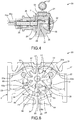
FIG. 4 is a sectional view taken substantially along line 4--4 ofFIG. 2 . -
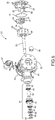
FIG. 5 is an exploded view of the internal gear pump showed inFIGS. 1-4 . -
FIG. 6 is a sectional view taken substantially alonglines 6--6 ofFIG. 1 -
FIG. 7 is a front plan view of the head shown inFIG. 5 . -
FIG. 8 is a perspective view of the head shown inFIGS. 5 and7 . -
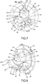
FIG. 9 is a front plan view of the head and idler shown inFIGS. 5 and6 and a sectional view of the rotor, particularly illustrating the engagement between the idler and rotor teeth. -
FIG. 10 is a front plan view of the head with the idler mounted there on. -
FIG. 11 is a perspective view of the head, idler and rotor. - The drawings are not necessarily to scale and may illustrate the disclosed embodiments diagrammatically and in partial views. In certain instances, this disclosure may omit details which are not necessary for an understanding of the disclosed methods and apparatuses or which render other details difficult to perceive. Further, this disclosure is not limited to the particular embodiment illustrated herein.
-
FIGS. 1-3 provide exterior views of a disclosedinternal gear pump 20. Thepump 20 includes thecasing 21 including aninlet 22 and anoutlet 23. Thecasing 21 further includes aninboard end 24 through which arotor shaft 25 passes in an openoutboard end 26 shown inFIG. 4 . Thecasing 21 may couple to arelief valve assembly 27, also shown inFIG. 5 . Further, as shown inFIGS. 3 and4 , therotor shaft 25 may define acentral axis 25a of thepump chamber 31. Further, as shown inFIGS. 2 and4 , the idler 33 rotates about anidler axis 33a offset from thecentral axis 25a of thepump chamber 31 androtor shaft 25. -
FIGS. 4-5 further illustrate various components of thepump 20. Therotor shaft 25 is connected arotor 28. Therotor 28 includes a plurality circumferentially spaced-apartrotor teeth 29. Therotor teeth 29 extend axially into a pump chamber 31(FIG. 4 ) that is defined by thecasing 21 and thehead 32, and which encloses theoutboard end 26 of thecasing 21 as shown inFIG. 4 . Therotor 28 and an idler 33 are disposed within thepump chamber 31. The idler 33 rotatably couples to thehead 32 using anidler bushing 34 and idler pin 35 (FIG.5 ). An O-ring 36 seals the connection between thehead 32 and the openoutboard end 26 of thecasing 21. Thehead 32 includes an inner surface 37 (FIGS. 6-8 ) that includes or connects to aboss 38, the details of which are described below in connection withFIGS. 7-8 . While the O-ring 36 andhead 32 seal the openoutboard end 26 of thecasing 21, therotor shaft 25 passes through theseal 39 to seal theinboard end 24 of thecasing 21. In addition to passing through theseal 39, therotor shaft 25 also passes through a bearingassembly 41 that may include aspacer 42, abearing 43, aspacer 44, a bearinghousing 45, abearing 46, aspacer 47, a bearingendcap 48, alock washer 49 and alock nut 50 as shown inFIG. 5 . -
FIG. 6 provides a front view of thepump chamber 31, the idler 33 and a sectional view of therotor 28. As noted above, thecasing 21 includes aninlet 22 and anoutlet 23. Theinlet 22 connects to thepump chamber 31 by aninlet passageway 22a and theoutlet 23 connects to thepump chamber 31 by anoutlet passageway 23a. Thepump 20 is configured so that therotor shaft 25,rotor 28, and idler 33 rotate in the clockwise direction. However, because of the symmetrical nature of theinlet 22 andoutlet 23 and the symmetrical nature of theinlet passageway 22a and theoutlet passageway 23a, the direction of thepump 20 may be easily reversed by changing thehead 32 without changing thecasing 21. Thus, thecasing 21 can accommodate flow in either direction. To reverse the flow of thepump 20, a mirror image of thehead 32 may be substituted for thehead 32 as shown, without changing thecasing 21, because theinlet 22 is disposed diametrically opposite thepump chamber 31 from the outlet 23 (and vice versa) and further because theinlet passageway 22a andoutlet passageway 23a are also symmetrical. In other words, the inlet andoutlet passageways central axis 25a (FIG. 4 ) of thepump chamber 31 and theidler axis 33a (FIG. 6 ). For example, in the example shown inFIG. 6 , such a plane mirror passes through theline 30 and extends perpendicularly out of the page. By locating theinlet 22 andoutlet 23 at the three o'clock and nine o'clock positions respectively and by employing symmetrical inlet andoutlet passages pump 20 may be more easily reversed and all a manufacturer needs to do is manufacture onecasing 21 and twoheads 32 that are mirror images of one another. - Applicant uses the terms top, bottom, vertical, horizontal, three o'clock position and nine o'clock position to assist the reader in understanding this description and the attached drawings. The disclosed
pump 20 need not be used exclusively in the orientation shown in the drawings where a horizontal plane passes through axial centers of theinlet 22 andoutlet 23 and a vertical plane passes through thecentral axis 25a andidler axis 33a (and theline 30 ofFIG. 6 ). In other words, theinlet 22 andoutlet 23 may be disposed in any common plane and said common plane need not be horizontal as the effects of gravity on liquids pumped at high speeds by the disclosedpump 20 are minimal. And, of course, the plane mirror for theinlet passageway 22a (and the inlet 22) and theoutlet passageway 23a (and the outlet 23) need not be vertical as indicated by theline 30 inFIG. 6 . - Still referring to
FIG. 6 , the idler 33 includes a plurality of radially outwardly extendingidler teeth 51 that are disposed between alternatingidler roots 52. In contrast to therotor teeth 29, theidler teeth 51 may taper as they extend radially outward away from theidler pin 35. The idler 33 may be fabricated from a high strength and/or hardened material to avoid damage from cavitation while operating thepump 20 at high speeds. Further, the circumferentially disposedrotor teeth 29 are separated byspaces 53, which receive theidler teeth 51 at the top of thepump 20 as shown inFIG. 6 (or equidistantly between theinlet 22 andoutlet 23 along the path of rotation of the rotor teeth 29). At the top of thepump 20, theidler teeth 51 intermesh with therotor teeth 29. As theidler teeth 51 and therotor teeth 29 rotate in the clockwise direction from the top of thepump 20 towards theinlet 22, theidler teeth 51 become disengaged from therotor teeth 29, which creates low-pressure areas near theinlet 22. These low-pressure areas draw liquid into thepump chamber 31 and towards the idler 33 and therotor 28. As theidler teeth 51 androtor teeth 29 rotate past theinlet 22, fluid disposed in theidler roots 52 is swept along anupper surface 54 of thecrescent 55 and liquid disposed in thespaces 53 between therotor teeth 29 is swept along alower surface 56 of thecrescent 55. At the bottom of thepump 20 as shown inFIG. 6 , theidler teeth 51 sweep along theupper surface 54 of thecrescent 55 and therotor teeth 29 sweep along thelower surface 56 of thecrescent 55. - Thus, the
crescent 55 serves as a seal between therotor teeth 29 and theidler teeth 51 at the bottom of thepump 20 until theidler teeth 51 and therotor teeth 29 reach theoutlet 23 where thecrescent 55 terminates at the tapered trailingend 55a and fluid flows out of thepump 20. Thecrescent 55 also features a tapered or pointed leadingend 55b, which facilitates or increases the feeding of the liquid at high pump speeds. As shown inFIG. 6 , the idler 33 oridler teeth 51 and therotor 28 orrotor teeth 29 come into a simultaneous sealing engagement with thecrescent 55 to provide a seal at the bottom of thepump 20 between theinlet 22 andoutlet 23. Simultaneously, a seal at the top of thepump 20 is created by the engagement between one of theidler teeth 51 and theupper wall 57 of thecasing 21 and the intermeshing of thatidler tooth 51 between tworotor teeth 29 as shown at the top ofFIG. 6 . Theupper wall 57 of thecasing 21 illustrated inFIG. 6 also abuts theupper wall 58 of theboss 38 of thehead 32, as illustrated inFIGS. 7-8 . The simultaneous sealing engagement between the idler 33 and theupper surface 54 of thecrescent 55, between therotor 28 and thelower surface 56 of the crescent and between the idler 33 and theupper wall 57 of thecasing 21 all combine to reduce slip while operating thepump 20 at high speeds. - Continuing with
FIGS. 7-8 , theboss 38 also includes alower wall 59. Additionally, theboss 38 includes anidler support 61, which supports the idler 33 in thepump chamber 31 and includes anopening 62 for receiving theidler pin 35 and the idler bushing 34 (FIG.5 ). Theboss 38 further includes amiddle wall 63 that connects theidler support 61 to acrescent support 64. Thecrescent support 64 supports thecrescent 55 in a proper orientation so that theidler teeth 51 sweep along theupper surface 54 of thecrescent 55 and so that therotor teeth 29 sweep along thelower surface 56 of thecrescent 55 at the bottom of thepump 20. As shown inFIGS. 7-8 , theidler support 61 terminates at anidler support surface 61a, thecrescent support 64 terminates at acrescent support surface 64a, theupper wall 58 terminates at anupper wall surface 58a, themiddle wall 63 terminates atmiddle wall surface 63a, and thelower wall 59 terminates at alower wall surface 59a. Theidler support surface 61a,crescent support surface 64a,upper wall surface 58a,middle wall surface 63a andlower wall surface 59a may be coplanar. - The
crescent support 64 includes aliquid directing step 65. Theliquid directing step 65, in combination with themiddle wall 63, theidler support 61 and theinner surface 37 of thehead 32 form anidler feed slot 66. Theidler feed slot 66 facilitates the feeding of liquid from theinlet 22 to theidler roots 52 for more efficient pumping and reduces cavitation at high pumping speeds. Similarly, theliquid directing step 65 in combination with thelower wall 59, thecasing 21 and theinner surface 37 of thehead 32 form arotor feed slot 67. Therotor feed slot 67 facilitates the channeling of liquid from theinlet 22 to thespaces 53 between therotor teeth 29 at the bottom of thepump 20. Like theidler feed slot 66, therotor feed slot 67 contributes to the ability of thepump 20 to operate at high speeds with reduced risk of cavitation. Thecrescent 55 extends outward away from theinner surface 37 of thehead 32 into thepump chamber 31 before terminating at anouter crescent surface 55a. The reader will note that theouter crescent surface 55a is disposed farther into thepump chamber 31 than thecrescent support surface 64a as best seen inFIG. 8 . - The
idler feed slot 66 androtor feed slot 67 are further illustrated inFIGS. 9-10 . Theidler feed slot 66 is separated from therotor feed slot 67 by theliquid directing step 65, which is essentially an extension of thecrescent support 64 or is a portion of thecrescent support 64 that extends arcuately beyond thecrescent 55 and towards theinlet 22. Segregating the incoming liquid into portions delivered to theidler feed slot 66 and therotor feed slot 67 reduces turbulence and cavitation and enables thepump 20 to operate at higher speeds. Further, theliquid directing step 65,idler feed slot 66 androtor feed slot 67 help eliminate non-ideal flow patterns, thereby allowing more liquid to enter thepump 20 before directing the liquid to either above the crescent 55 (or into the idler feed slot 66) or below the crescent 55 (or into the rotor feed slot 67). - In the embodiment shown, the
boss 38 creates theidler feed slot 66 androtor feed slot 67 by supporting the idler 33 and thecrescent 55 outward away from theinner surface 37 of thehead 32. This gap or clearance between theinner surface 37 of thehead 32 and both the idler 33 androtor 28 creates the space necessary for the formation of theidler feed slot 66 androtor feed slot 67. The additional space required for the formation of theidler feed slot 66 androtor feed slot 67 accommodates alarger inlet 22 for increased pumping speeds. - As shown in
FIG. 11 , theboss 38 includes anupper wall 58 that blocks fluid from flowing from theoutlet 23 back to theinlet 22 and, instead, forces fluid to exit through theoutlet 23. Further, thelower wall 59 forms part of therotor feed slot 67 and forces liquid between therotor teeth 29 before it exits through theoutlet 23. - An
internal gear pump 20 enables faster operation with reduced risk of or simply reduced cavitation. The disclosedpump 20 can operate at higher speeds because of the combination of anidler feed slot 66 and arotor feed slot 67 that is created by ahead 32 and aboss 38. Depending on the size of thepump 20, thepump 20 can operate at up to 20-30% higher speeds than internal gear pumps with just idler feed slots, such as that disclosed in commonly assignedUS6149415 , and thepump 20 can operate at up to twice the speed of internal gears pumps that predateUS6149415 . Theboss 38 includes anidler support 61 that supports the idler 33 in thepump chamber 31 and spaced apart from theinner surface 37 of thehead 32. Similarly, thecrescent 55 is also supported away from theinner surface 37 by theboss 38 or, more specifically, by thecrescent support 64 of theboss 38. The spacing between the idler 33, thecrescent support 64, and the axial ends of therotor teeth 29 provide the needed space to form theidler feed slot 66 and therotor feed slot 67. Specifically, theidler support 61, themiddle wall 63, theliquid directing step 65 and theinner surface 37 of thehead 32 may define anidler feed slot 66. Further, therotor feed slot 67 may be defined by thecasing 21, thelower wall 59, theliquid directing step 65 and theinner surface 37 of thehead 32. Thus, liquid entering through theinlet 22 is separated by theliquid directing step 65 into a portion that enters theidler feed slot 66 and another portion that enters therotor feed slot 67. Dividing the incoming liquid in this way enables thepump 20 to operate at higher speeds, lower turbulence, and reduced risk of cavitation and/or reduced cavitation.
Claims (12)
- An internal gear pump (20) comprising:a casing (21) comprising an inlet (22), an outlet (23), an open outboard end (26) and an inboard end (24) through which a rotor shaft (25) passes, the open outboard end enclosed by a head (32), the head and casing defining a pump chamber (31), the rotor shaft connected to a rotor (28) disposed in the pump chamber, characterized in thatthe head includes an inner surface (37) that faces the pump chamber, the inner surface connected to a boss (38) that extends into the pump chamber, the boss comprising an idler support (61) connected to a crescent support (64), the idler support rotatably connected to an idler (33),the crescent support partially covered by and connected to a crescent (55) that extends away from the head and that is disposed below the idler, the crescent support further comprising a liquid directing step (65) that extends arcuately from the crescent support beyond the crescent and towards the inlet, the boss (38) further comprises a middle wall (63) that connects the crescent support (64) to the idler support (61), the boss (38) and the head (32) defining an idler feed slot (66) between the liquid directing step (65) and the idler support (61) and extending from the middle wall towards the inlet (22) for providing communication between the inlet and the idler, the boss comprising a lower wall (59) disposed below the crescent support and that extends from the crescent support downward to the casing, the boss, inner surface of the head and casing defining a rotor feed slot (67) between the liquid directing step and the casing and extending from the lower wall towards the inlet for providing communication between the inlet and the rotor.
- The internal gear pump of claim 1, wherein the rotor (28) comprises a plurality of circumferentially disposed rotor teeth (29) extending radially inwards towards the central axis, the idler comprising a plurality of idler teeth extending radially outwards away from the idler axis.
- The pump according to any one of the preceding claims wherein the boss further comprises a middle wall (63) that connects the crescent support (64) to the idler support (61), the boss and head defining an idler feed slot (67) between the liquid directing step (65) and the idler support and extending from the middle wall towards the inlet for providing communication between the inlet and the idler teeth.
- The pump according to any one of the preceding claims wherein the crescent includes a tapered leading edge (55b).
- The pump according to any one of the preceding claims wherein the boss further comprises an upper wall (58) disposed opposite the idler axis from the crescent (55) and that extends from the idler support (61) upward to the casing (21).
- The pump according to claim 5 wherein the upper wall (58), lower wall (59), idler support (61) and crescent support (64) terminate at surfaces that are coplanar with respect to each other.
- The pump according to any one of the preceding claims wherein the boss (38) further comprises an upper wall disposed opposite the idler axis from the crescent (55) and that extends from the idler support upward to the casing (21).
- The pump according to claim 7 wherein the upper wall, middle wall (58), lower wall (59), idler support (61) and crescent support (64) terminate at surfaces that are coplanar with respect to each other.
- The pump according to any one of the preceding claims wherein the idler support (61) and crescent support (64) terminate at surfaces that are coplanar with each other.
- The pump according to any one of the preceding claims wherein the pump chamber (31) has a central axis and the idler (33) rotates about an idler axis, the inlet (22) connects to the pump chamber by an inlet passageway and the outlet (23) connects to the pump chamber by an outlet passageway, the inlet and inlet passageway being mirror images of the outlet and outlet passageway respectively with respect to a plane mirror that passes through the central axis and the idler axis.
- A method for pumping liquid at a high speed, the method comprising:providing an internal gear pump (20) comprising a casing (21) comprising an inlet (22), an outlet (23), an open outboard end (26) and an inboard end (24) through which a rotor shaft (25) passes, the open outboard end enclosed by a head, the head and casing defining a pump chamber (31), the rotor shaft connected to a rotor (28) disposed in the pump chamber, the head including an inner surface that faces the pump chamber, the inner surface connected to a boss (38) extending from the inner surface into the pump chamber, the boss comprising an idler support connected to a crescent support by a middle wall, the idler support rotatably connected to an idler, the crescent support (64) partially covered by and connected to a crescent that extends away from the head and that is disposed below the idler, the crescent support further comprising a liquid directing step (65) that extends from the crescent (55) and towards the inlet, the boss (38) and the head (32) defining an idler feed slot (66) between the liquid directing step (65) and the idler support (61) and extending from the middle wall towards the inlet, the rotor comprising a plurality of circumferentially disposed rotor teeth (29) extending radially inwards towards the central axis, the idler comprising a plurality of idler teeth extending radially outwards away from the idler axis and disposed radially within the rotor teeth, the boss comprising a lower wall disposed below the crescent support and that extends from the crescent support downward to the casing, the boss, casing and inner surface of the head defining a rotor feed slot (67) between the liquid directing step and the casing and extending from the lower wall towards the inlet;rotating the rotor shaft (25) and rotor;directing fluid from the inlet (22) and through the idler feed slot to the idler teeth; anddirecting fluid from the inlet and through the rotor feed slot to the rotor teeth (29).
- The method of claim 11 further comprising providing an upper wall disposed opposite the idler axis from the crescent (55) and that extends from the idler support upward to the casing (21);
blocking flow from the inlet to the outlet and vice versa with the upper and lower walls without said flow first being fed to either the rotor (28) or the idler (33).
Applications Claiming Priority (1)
| Application Number | Priority Date | Filing Date | Title |
|---|---|---|---|
| US14/681,279 US9683564B2 (en) | 2015-04-08 | 2015-04-08 | Internal gear pump with improved communication between inlet and idler and between inlet and rotor |
Publications (2)
| Publication Number | Publication Date |
|---|---|
| EP3078857A1 EP3078857A1 (en) | 2016-10-12 |
| EP3078857B1 true EP3078857B1 (en) | 2018-01-03 |
Family
ID=55701863
Family Applications (1)
| Application Number | Title | Priority Date | Filing Date |
|---|---|---|---|
| EP16164541.1A Active EP3078857B1 (en) | 2015-04-08 | 2016-04-08 | High speed internal gear pump |
Country Status (4)
| Country | Link |
|---|---|
| US (1) | US9683564B2 (en) |
| EP (1) | EP3078857B1 (en) |
| CA (1) | CA2924115C (en) |
| DK (1) | DK3078857T3 (en) |
Families Citing this family (4)
| Publication number | Priority date | Publication date | Assignee | Title |
|---|---|---|---|---|
| CN111486090B (en) * | 2020-06-02 | 2025-06-24 | 北京威浦实信科技有限公司 | Internal gear pump |
| US20240102471A1 (en) * | 2022-09-23 | 2024-03-28 | Viking Pump, Inc. | Universal pump bracket |
| US20250116271A1 (en) * | 2023-10-06 | 2025-04-10 | Viking Pump, Inc. | Process pump with dynamic seal for dry run capability |
| CN117267123A (en) * | 2023-10-07 | 2023-12-22 | 重庆清川流体设备有限公司 | Novel bidirectional gear pump |
Family Cites Families (9)
| Publication number | Priority date | Publication date | Assignee | Title |
|---|---|---|---|---|
| US1496737A (en) * | 1922-06-03 | 1924-06-03 | Viking Pump Company | Rotary pump, motor, or engine |
| US1896033A (en) * | 1928-09-13 | 1933-01-31 | Mechanical Devices Company | Rotary pump |
| US1853430A (en) * | 1930-02-20 | 1932-04-12 | Viking Pump Company | Rotary pump |
| US2481560A (en) * | 1947-05-31 | 1949-09-13 | Viking Pump Company | Sanitary pump |
| US3276387A (en) * | 1964-08-17 | 1966-10-04 | Lucas Industries Ltd | Gear pumps |
| US5322428A (en) * | 1992-12-07 | 1994-06-21 | The Gorman-Rupp Company | Gear transfer pump with lubrication and sealing of the driveshaft and idler pin |
| US6149415A (en) * | 1999-02-11 | 2000-11-21 | Viking Pump, Inc. | Internal gear pump having a feed groove aligned with the roots of the idler teeth |
| US6158994A (en) | 1999-04-21 | 2000-12-12 | Tuthill Corporation | Grooved rotor for an internal gear pump |
| US6659728B2 (en) | 2001-11-09 | 2003-12-09 | Viking Pump, Inc. | Liquid dispensing pump system |
-
2015
- 2015-04-08 US US14/681,279 patent/US9683564B2/en active Active
-
2016
- 2016-03-17 CA CA2924115A patent/CA2924115C/en active Active
- 2016-04-08 DK DK16164541.1T patent/DK3078857T3/en active
- 2016-04-08 EP EP16164541.1A patent/EP3078857B1/en active Active
Non-Patent Citations (1)
| Title |
|---|
| None * |
Also Published As
| Publication number | Publication date |
|---|---|
| US20160298623A1 (en) | 2016-10-13 |
| DK3078857T3 (en) | 2018-03-26 |
| CA2924115C (en) | 2021-01-05 |
| CA2924115A1 (en) | 2016-10-08 |
| EP3078857A1 (en) | 2016-10-12 |
| US9683564B2 (en) | 2017-06-20 |
Similar Documents
| Publication | Publication Date | Title |
|---|---|---|
| CA2924115C (en) | High speed internal gear pump | |
| US4481020A (en) | Liquid-gas separator apparatus | |
| US20180128272A1 (en) | Dual inlet volute, impeller and pump housing for same, and related methods | |
| SE456028B (en) | CIRCULATIVE OR CYLINDRICAL PORT PART | |
| US8469654B2 (en) | Fluid machine | |
| EP3828415A1 (en) | Internal gear pump | |
| AU6009701A (en) | Feed pump | |
| US11624365B2 (en) | Fluid delivery device | |
| RU2769329C2 (en) | Multistage pump with improved head balancing properties | |
| US20100021282A1 (en) | Side-Channel Pump | |
| CN107110154A (en) | Transfer device | |
| US20130287558A1 (en) | Low flow-high pressure centrifugal pump | |
| US10215154B2 (en) | Eccentrically piloted hydraulic commutator | |
| JP6438576B2 (en) | Vane pump and profile determination method inside cam ring constituting the same | |
| US10514034B2 (en) | Idler gear for positive displacement gear pump | |
| CN108026919B (en) | Pump mounting structure for power steering | |
| EP2208891B1 (en) | Minipump | |
| US6425748B1 (en) | Positive displacement rotary pump | |
| JP2005240763A (en) | Liquid pump | |
| JP7320994B2 (en) | multistage pump | |
| JP6152745B2 (en) | Gear pump | |
| EP3354897B1 (en) | Volumetric machine | |
| JP2015038356A (en) | Impeller for submerged pump and submerged pump | |
| US12546313B2 (en) | External gear pump | |
| CA2781051A1 (en) | Ice slurry pump |
Legal Events
| Date | Code | Title | Description |
|---|---|---|---|
| PUAI | Public reference made under article 153(3) epc to a published international application that has entered the european phase |
Free format text: ORIGINAL CODE: 0009012 |
|
| AK | Designated contracting states |
Kind code of ref document: A1 Designated state(s): AL AT BE BG CH CY CZ DE DK EE ES FI FR GB GR HR HU IE IS IT LI LT LU LV MC MK MT NL NO PL PT RO RS SE SI SK SM TR |
|
| AX | Request for extension of the european patent |
Extension state: BA ME |
|
| 17P | Request for examination filed |
Effective date: 20170411 |
|
| RBV | Designated contracting states (corrected) |
Designated state(s): AL AT BE BG CH CY CZ DE DK EE ES FI FR GB GR HR HU IE IS IT LI LT LU LV MC MK MT NL NO PL PT RO RS SE SI SK SM TR |
|
| RIC1 | Information provided on ipc code assigned before grant |
Ipc: F04C 2/08 20060101ALI20170531BHEP Ipc: F04C 2/10 20060101AFI20170531BHEP Ipc: F04C 14/18 20060101ALI20170531BHEP Ipc: F01C 1/10 20060101ALI20170531BHEP Ipc: F04C 15/00 20060101ALI20170531BHEP |
|
| GRAP | Despatch of communication of intention to grant a patent |
Free format text: ORIGINAL CODE: EPIDOSNIGR1 |
|
| INTG | Intention to grant announced |
Effective date: 20170725 |
|
| GRAS | Grant fee paid |
Free format text: ORIGINAL CODE: EPIDOSNIGR3 |
|
| GRAA | (expected) grant |
Free format text: ORIGINAL CODE: 0009210 |
|
| AK | Designated contracting states |
Kind code of ref document: B1 Designated state(s): AL AT BE BG CH CY CZ DE DK EE ES FI FR GB GR HR HU IE IS IT LI LT LU LV MC MK MT NL NO PL PT RO RS SE SI SK SM TR |
|
| REG | Reference to a national code |
Ref country code: GB Ref legal event code: FG4D |
|
| REG | Reference to a national code |
Ref country code: CH Ref legal event code: EP Ref country code: AT Ref legal event code: REF Ref document number: 960547 Country of ref document: AT Kind code of ref document: T Effective date: 20180115 |
|
| REG | Reference to a national code |
Ref country code: IE Ref legal event code: FG4D |
|
| REG | Reference to a national code |
Ref country code: DE Ref legal event code: R096 Ref document number: 602016001266 Country of ref document: DE |
|
| REG | Reference to a national code |
Ref country code: DK Ref legal event code: T3 Effective date: 20180322 |
|
| REG | Reference to a national code |
Ref country code: NL Ref legal event code: FP |
|
| REG | Reference to a national code |
Ref country code: FR Ref legal event code: PLFP Year of fee payment: 3 |
|
| REG | Reference to a national code |
Ref country code: LT Ref legal event code: MG4D |
|
| REG | Reference to a national code |
Ref country code: AT Ref legal event code: MK05 Ref document number: 960547 Country of ref document: AT Kind code of ref document: T Effective date: 20180103 |
|
| PG25 | Lapsed in a contracting state [announced via postgrant information from national office to epo] |
Ref country code: FI Free format text: LAPSE BECAUSE OF FAILURE TO SUBMIT A TRANSLATION OF THE DESCRIPTION OR TO PAY THE FEE WITHIN THE PRESCRIBED TIME-LIMIT Effective date: 20180103 Ref country code: LT Free format text: LAPSE BECAUSE OF FAILURE TO SUBMIT A TRANSLATION OF THE DESCRIPTION OR TO PAY THE FEE WITHIN THE PRESCRIBED TIME-LIMIT Effective date: 20180103 Ref country code: CY Free format text: LAPSE BECAUSE OF FAILURE TO SUBMIT A TRANSLATION OF THE DESCRIPTION OR TO PAY THE FEE WITHIN THE PRESCRIBED TIME-LIMIT Effective date: 20180103 Ref country code: ES Free format text: LAPSE BECAUSE OF FAILURE TO SUBMIT A TRANSLATION OF THE DESCRIPTION OR TO PAY THE FEE WITHIN THE PRESCRIBED TIME-LIMIT Effective date: 20180103 Ref country code: HR Free format text: LAPSE BECAUSE OF FAILURE TO SUBMIT A TRANSLATION OF THE DESCRIPTION OR TO PAY THE FEE WITHIN THE PRESCRIBED TIME-LIMIT Effective date: 20180103 Ref country code: NO Free format text: LAPSE BECAUSE OF FAILURE TO SUBMIT A TRANSLATION OF THE DESCRIPTION OR TO PAY THE FEE WITHIN THE PRESCRIBED TIME-LIMIT Effective date: 20180403 |
|
| PG25 | Lapsed in a contracting state [announced via postgrant information from national office to epo] |
Ref country code: BG Free format text: LAPSE BECAUSE OF FAILURE TO SUBMIT A TRANSLATION OF THE DESCRIPTION OR TO PAY THE FEE WITHIN THE PRESCRIBED TIME-LIMIT Effective date: 20180403 Ref country code: GR Free format text: LAPSE BECAUSE OF FAILURE TO SUBMIT A TRANSLATION OF THE DESCRIPTION OR TO PAY THE FEE WITHIN THE PRESCRIBED TIME-LIMIT Effective date: 20180404 Ref country code: AT Free format text: LAPSE BECAUSE OF FAILURE TO SUBMIT A TRANSLATION OF THE DESCRIPTION OR TO PAY THE FEE WITHIN THE PRESCRIBED TIME-LIMIT Effective date: 20180103 Ref country code: RS Free format text: LAPSE BECAUSE OF FAILURE TO SUBMIT A TRANSLATION OF THE DESCRIPTION OR TO PAY THE FEE WITHIN THE PRESCRIBED TIME-LIMIT Effective date: 20180103 Ref country code: PL Free format text: LAPSE BECAUSE OF FAILURE TO SUBMIT A TRANSLATION OF THE DESCRIPTION OR TO PAY THE FEE WITHIN THE PRESCRIBED TIME-LIMIT Effective date: 20180103 Ref country code: SE Free format text: LAPSE BECAUSE OF FAILURE TO SUBMIT A TRANSLATION OF THE DESCRIPTION OR TO PAY THE FEE WITHIN THE PRESCRIBED TIME-LIMIT Effective date: 20180103 Ref country code: IS Free format text: LAPSE BECAUSE OF FAILURE TO SUBMIT A TRANSLATION OF THE DESCRIPTION OR TO PAY THE FEE WITHIN THE PRESCRIBED TIME-LIMIT Effective date: 20180503 Ref country code: LV Free format text: LAPSE BECAUSE OF FAILURE TO SUBMIT A TRANSLATION OF THE DESCRIPTION OR TO PAY THE FEE WITHIN THE PRESCRIBED TIME-LIMIT Effective date: 20180103 |
|
| REG | Reference to a national code |
Ref country code: DE Ref legal event code: R097 Ref document number: 602016001266 Country of ref document: DE |
|
| PG25 | Lapsed in a contracting state [announced via postgrant information from national office to epo] |
Ref country code: EE Free format text: LAPSE BECAUSE OF FAILURE TO SUBMIT A TRANSLATION OF THE DESCRIPTION OR TO PAY THE FEE WITHIN THE PRESCRIBED TIME-LIMIT Effective date: 20180103 Ref country code: AL Free format text: LAPSE BECAUSE OF FAILURE TO SUBMIT A TRANSLATION OF THE DESCRIPTION OR TO PAY THE FEE WITHIN THE PRESCRIBED TIME-LIMIT Effective date: 20180103 |
|
| PLBE | No opposition filed within time limit |
Free format text: ORIGINAL CODE: 0009261 |
|
| STAA | Information on the status of an ep patent application or granted ep patent |
Free format text: STATUS: NO OPPOSITION FILED WITHIN TIME LIMIT |
|
| PG25 | Lapsed in a contracting state [announced via postgrant information from national office to epo] |
Ref country code: CZ Free format text: LAPSE BECAUSE OF FAILURE TO SUBMIT A TRANSLATION OF THE DESCRIPTION OR TO PAY THE FEE WITHIN THE PRESCRIBED TIME-LIMIT Effective date: 20180103 Ref country code: MC Free format text: LAPSE BECAUSE OF FAILURE TO SUBMIT A TRANSLATION OF THE DESCRIPTION OR TO PAY THE FEE WITHIN THE PRESCRIBED TIME-LIMIT Effective date: 20180103 Ref country code: SM Free format text: LAPSE BECAUSE OF FAILURE TO SUBMIT A TRANSLATION OF THE DESCRIPTION OR TO PAY THE FEE WITHIN THE PRESCRIBED TIME-LIMIT Effective date: 20180103 Ref country code: SK Free format text: LAPSE BECAUSE OF FAILURE TO SUBMIT A TRANSLATION OF THE DESCRIPTION OR TO PAY THE FEE WITHIN THE PRESCRIBED TIME-LIMIT Effective date: 20180103 |
|
| 26N | No opposition filed |
Effective date: 20181005 |
|
| REG | Reference to a national code |
Ref country code: BE Ref legal event code: MM Effective date: 20180430 |
|
| REG | Reference to a national code |
Ref country code: IE Ref legal event code: MM4A |
|
| PG25 | Lapsed in a contracting state [announced via postgrant information from national office to epo] |
Ref country code: LU Free format text: LAPSE BECAUSE OF NON-PAYMENT OF DUE FEES Effective date: 20180408 |
|
| PG25 | Lapsed in a contracting state [announced via postgrant information from national office to epo] |
Ref country code: BE Free format text: LAPSE BECAUSE OF NON-PAYMENT OF DUE FEES Effective date: 20180430 Ref country code: SI Free format text: LAPSE BECAUSE OF FAILURE TO SUBMIT A TRANSLATION OF THE DESCRIPTION OR TO PAY THE FEE WITHIN THE PRESCRIBED TIME-LIMIT Effective date: 20180103 |
|
| PG25 | Lapsed in a contracting state [announced via postgrant information from national office to epo] |
Ref country code: IE Free format text: LAPSE BECAUSE OF NON-PAYMENT OF DUE FEES Effective date: 20180408 |
|
| REG | Reference to a national code |
Ref country code: CH Ref legal event code: PL |
|
| PG25 | Lapsed in a contracting state [announced via postgrant information from national office to epo] |
Ref country code: LI Free format text: LAPSE BECAUSE OF NON-PAYMENT OF DUE FEES Effective date: 20190430 Ref country code: MT Free format text: LAPSE BECAUSE OF NON-PAYMENT OF DUE FEES Effective date: 20180408 Ref country code: CH Free format text: LAPSE BECAUSE OF NON-PAYMENT OF DUE FEES Effective date: 20190430 |
|
| PG25 | Lapsed in a contracting state [announced via postgrant information from national office to epo] |
Ref country code: TR Free format text: LAPSE BECAUSE OF FAILURE TO SUBMIT A TRANSLATION OF THE DESCRIPTION OR TO PAY THE FEE WITHIN THE PRESCRIBED TIME-LIMIT Effective date: 20180103 |
|
| PG25 | Lapsed in a contracting state [announced via postgrant information from national office to epo] |
Ref country code: PT Free format text: LAPSE BECAUSE OF FAILURE TO SUBMIT A TRANSLATION OF THE DESCRIPTION OR TO PAY THE FEE WITHIN THE PRESCRIBED TIME-LIMIT Effective date: 20180103 |
|
| PG25 | Lapsed in a contracting state [announced via postgrant information from national office to epo] |
Ref country code: MK Free format text: LAPSE BECAUSE OF NON-PAYMENT OF DUE FEES Effective date: 20180103 Ref country code: RO Free format text: LAPSE BECAUSE OF FAILURE TO SUBMIT A TRANSLATION OF THE DESCRIPTION OR TO PAY THE FEE WITHIN THE PRESCRIBED TIME-LIMIT Effective date: 20180103 Ref country code: HU Free format text: LAPSE BECAUSE OF FAILURE TO SUBMIT A TRANSLATION OF THE DESCRIPTION OR TO PAY THE FEE WITHIN THE PRESCRIBED TIME-LIMIT; INVALID AB INITIO Effective date: 20160408 |
|
| PGFP | Annual fee paid to national office [announced via postgrant information from national office to epo] |
Ref country code: NL Payment date: 20250418 Year of fee payment: 10 |
|
| PGFP | Annual fee paid to national office [announced via postgrant information from national office to epo] |
Ref country code: DE Payment date: 20250422 Year of fee payment: 10 |
|
| PGFP | Annual fee paid to national office [announced via postgrant information from national office to epo] |
Ref country code: GB Payment date: 20250423 Year of fee payment: 10 Ref country code: DK Payment date: 20250429 Year of fee payment: 10 |
|
| PGFP | Annual fee paid to national office [announced via postgrant information from national office to epo] |
Ref country code: IT Payment date: 20250424 Year of fee payment: 10 |
|
| PGFP | Annual fee paid to national office [announced via postgrant information from national office to epo] |
Ref country code: FR Payment date: 20250425 Year of fee payment: 10 |