EP3078809B2 - Rotating labyrinth m-seal - Google Patents
Rotating labyrinth m-seal Download PDFInfo
- Publication number
- EP3078809B2 EP3078809B2 EP16164679.9A EP16164679A EP3078809B2 EP 3078809 B2 EP3078809 B2 EP 3078809B2 EP 16164679 A EP16164679 A EP 16164679A EP 3078809 B2 EP3078809 B2 EP 3078809B2
- Authority
- EP
- European Patent Office
- Prior art keywords
- seal
- segments
- segment
- barrel
- lands
- Prior art date
- Legal status (The legal status is an assumption and is not a legal conclusion. Google has not performed a legal analysis and makes no representation as to the accuracy of the status listed.)
- Active
Links
Images
Classifications
-
- F—MECHANICAL ENGINEERING; LIGHTING; HEATING; WEAPONS; BLASTING
- F01—MACHINES OR ENGINES IN GENERAL; ENGINE PLANTS IN GENERAL; STEAM ENGINES
- F01D—NON-POSITIVE DISPLACEMENT MACHINES OR ENGINES, e.g. STEAM TURBINES
- F01D11/00—Preventing or minimising internal leakage of working-fluid, e.g. between stages
- F01D11/02—Preventing or minimising internal leakage of working-fluid, e.g. between stages by non-contact sealings, e.g. of labyrinth type
-
- F—MECHANICAL ENGINEERING; LIGHTING; HEATING; WEAPONS; BLASTING
- F01—MACHINES OR ENGINES IN GENERAL; ENGINE PLANTS IN GENERAL; STEAM ENGINES
- F01D—NON-POSITIVE DISPLACEMENT MACHINES OR ENGINES, e.g. STEAM TURBINES
- F01D5/00—Blades; Blade-carrying members; Heating, heat-insulating, cooling or antivibration means on the blades or the members
- F01D5/12—Blades
- F01D5/22—Blade-to-blade connections, e.g. for damping vibrations
- F01D5/225—Blade-to-blade connections, e.g. for damping vibrations by shrouding
-
- F—MECHANICAL ENGINEERING; LIGHTING; HEATING; WEAPONS; BLASTING
- F04—POSITIVE - DISPLACEMENT MACHINES FOR LIQUIDS; PUMPS FOR LIQUIDS OR ELASTIC FLUIDS
- F04D—NON-POSITIVE-DISPLACEMENT PUMPS
- F04D29/00—Details, component parts, or accessories
- F04D29/08—Sealings
- F04D29/083—Sealings especially adapted for elastic fluid pumps
-
- F—MECHANICAL ENGINEERING; LIGHTING; HEATING; WEAPONS; BLASTING
- F04—POSITIVE - DISPLACEMENT MACHINES FOR LIQUIDS; PUMPS FOR LIQUIDS OR ELASTIC FLUIDS
- F04D—NON-POSITIVE-DISPLACEMENT PUMPS
- F04D29/00—Details, component parts, or accessories
- F04D29/26—Rotors specially for elastic fluids
- F04D29/32—Rotors specially for elastic fluids for axial flow pumps
- F04D29/321—Rotors specially for elastic fluids for axial flow pumps for axial flow compressors
-
- F—MECHANICAL ENGINEERING; LIGHTING; HEATING; WEAPONS; BLASTING
- F16—ENGINEERING ELEMENTS AND UNITS; GENERAL MEASURES FOR PRODUCING AND MAINTAINING EFFECTIVE FUNCTIONING OF MACHINES OR INSTALLATIONS; THERMAL INSULATION IN GENERAL
- F16J—PISTONS; CYLINDERS; SEALINGS
- F16J15/00—Sealings
- F16J15/44—Free-space packings
- F16J15/447—Labyrinth packings
-
- F—MECHANICAL ENGINEERING; LIGHTING; HEATING; WEAPONS; BLASTING
- F05—INDEXING SCHEMES RELATING TO ENGINES OR PUMPS IN VARIOUS SUBCLASSES OF CLASSES F01-F04
- F05D—INDEXING SCHEME FOR ASPECTS RELATING TO NON-POSITIVE-DISPLACEMENT MACHINES OR ENGINES, GAS-TURBINES OR JET-PROPULSION PLANTS
- F05D2220/00—Application
- F05D2220/30—Application in turbines
- F05D2220/32—Application in turbines in gas turbines
-
- F—MECHANICAL ENGINEERING; LIGHTING; HEATING; WEAPONS; BLASTING
- F05—INDEXING SCHEMES RELATING TO ENGINES OR PUMPS IN VARIOUS SUBCLASSES OF CLASSES F01-F04
- F05D—INDEXING SCHEME FOR ASPECTS RELATING TO NON-POSITIVE-DISPLACEMENT MACHINES OR ENGINES, GAS-TURBINES OR JET-PROPULSION PLANTS
- F05D2240/00—Components
- F05D2240/55—Seals
-
- F—MECHANICAL ENGINEERING; LIGHTING; HEATING; WEAPONS; BLASTING
- F05—INDEXING SCHEMES RELATING TO ENGINES OR PUMPS IN VARIOUS SUBCLASSES OF CLASSES F01-F04
- F05D—INDEXING SCHEME FOR ASPECTS RELATING TO NON-POSITIVE-DISPLACEMENT MACHINES OR ENGINES, GAS-TURBINES OR JET-PROPULSION PLANTS
- F05D2250/00—Geometry
- F05D2250/10—Two-dimensional
- F05D2250/18—Two-dimensional patterned
- F05D2250/183—Two-dimensional patterned zigzag
-
- F—MECHANICAL ENGINEERING; LIGHTING; HEATING; WEAPONS; BLASTING
- F05—INDEXING SCHEMES RELATING TO ENGINES OR PUMPS IN VARIOUS SUBCLASSES OF CLASSES F01-F04
- F05D—INDEXING SCHEME FOR ASPECTS RELATING TO NON-POSITIVE-DISPLACEMENT MACHINES OR ENGINES, GAS-TURBINES OR JET-PROPULSION PLANTS
- F05D2250/00—Geometry
- F05D2250/20—Three-dimensional
- F05D2250/23—Three-dimensional prismatic
- F05D2250/232—Three-dimensional prismatic conical
-
- F—MECHANICAL ENGINEERING; LIGHTING; HEATING; WEAPONS; BLASTING
- F05—INDEXING SCHEMES RELATING TO ENGINES OR PUMPS IN VARIOUS SUBCLASSES OF CLASSES F01-F04
- F05D—INDEXING SCHEME FOR ASPECTS RELATING TO NON-POSITIVE-DISPLACEMENT MACHINES OR ENGINES, GAS-TURBINES OR JET-PROPULSION PLANTS
- F05D2250/00—Geometry
- F05D2250/70—Shape
- F05D2250/75—Shape given by its similarity to a letter, e.g. T-shaped
-
- F—MECHANICAL ENGINEERING; LIGHTING; HEATING; WEAPONS; BLASTING
- F05—INDEXING SCHEMES RELATING TO ENGINES OR PUMPS IN VARIOUS SUBCLASSES OF CLASSES F01-F04
- F05D—INDEXING SCHEME FOR ASPECTS RELATING TO NON-POSITIVE-DISPLACEMENT MACHINES OR ENGINES, GAS-TURBINES OR JET-PROPULSION PLANTS
- F05D2260/00—Function
- F05D2260/94—Functionality given by mechanical stress related aspects such as low cycle fatigue [LCF] of high cycle fatigue [HCF]
- F05D2260/941—Functionality given by mechanical stress related aspects such as low cycle fatigue [LCF] of high cycle fatigue [HCF] particularly aimed at mechanical or thermal stress reduction
-
- Y—GENERAL TAGGING OF NEW TECHNOLOGICAL DEVELOPMENTS; GENERAL TAGGING OF CROSS-SECTIONAL TECHNOLOGIES SPANNING OVER SEVERAL SECTIONS OF THE IPC; TECHNICAL SUBJECTS COVERED BY FORMER USPC CROSS-REFERENCE ART COLLECTIONS [XRACs] AND DIGESTS
- Y02—TECHNOLOGIES OR APPLICATIONS FOR MITIGATION OR ADAPTATION AGAINST CLIMATE CHANGE
- Y02T—CLIMATE CHANGE MITIGATION TECHNOLOGIES RELATED TO TRANSPORTATION
- Y02T50/00—Aeronautics or air transport
- Y02T50/60—Efficient propulsion technologies, e.g. for aircraft
Definitions
- labyrinth seals are used to seal off cavities of higher and lower pressures in areas where there is relative rotational motion.
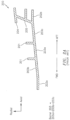
- FIG. 2A a labyrinth seal 200 in accordance with the prior art is shown.
- the seal 200 includes knife edges 201 that are used to create the sealing.
- the edges 201 rub against a variety of materials and may vary in terms of size, shape, count, angle, orientation, height, and width.
- the seal 200 includes attachment lands 202a and 202b.
- the land 202a is forward of the land 202b.
- One or both of the lands 202a and 202b can be a tight or snap fit.
- the snaps can be scalloped to allow air flow through the snap.
- the seal 200 includes segments 203a, 203b, and 203c (which, when taken collectively, are referred to as the barrel 203 herein).
- the barrel 203 extends from the forward attachment land 202-a in the aft direction.
- the seal 200 includes a hammerhead 204.
- the hammerhead 204 may have multiple uses but in the context of this disclosure the hammerhead 204 is used to create a(nother) sealing cavity.
- the seal 200 includes tabs 205.
- the tabs 205 are used to prevent rotation, thereby serving as an anti-rotation mechanism.
- the seal 200 is subjected to stress and large thermal gradients when placed into operational use, leading to component fatigue and a reduction in terms of component lifetime.
- stress may be a result of the lands 202a and 202b being coupled to a large material mass (e.g., a disc - not shown in FIG. 2B ), whereas the barrel 203 may be composed of a thin mass of material that interfaces to a hot airflow associated with a gas path.
- the large material mass/discs operate at a cooler temperature than the seal 200, and thus, do not grow as much as the seal 200 in a radially outboard direction (see the radial reference direction superimposed in FIG. 2A ). Consequently, the barrel 203 may be compelled to deflect in the radial reference direction. The deflections could be large, potentially causing the barrel 203 to crack.
- EP 2218879 A2 , WO 2013/001240 A1 and US 5211535 A disclose features of the preamble of claim 1, and WO 2016/059348 A1 is prior art under Art. 54(3) EPC.
- At least one of the segments is of a non-uniform width. In some embodiments, at least one of the segments is tapered in terms of width. In some embodiments, the barrel is substantially symmetrical in terms of shape. In some embodiments, the barrel is substantially asymmetrical in terms of shape. In some embodiments, a first length associated with a first of the segments is different from a second length associated with a second of the segments. In some embodiments, a first orientation associated with a first of the segments is different from a second orientation associated with a second of the segments. In some embodiments, the segments form a plurality of non-linear portions.
- At least one of the lands is configured to couple to a disc, and the barrel is configured to interface to a gas path flow.
- the seal is configured to seal a fluid between two or more cavities.
- the lands are configured to interface a first section of the engine to a second section of the engine.
- the seal is configured to interface a low pressure turbine and a high pressure turbine.
- the seal is configured to interface a low pressure compressor and a high pressure compressor.
- a ratio of a diameter of at least one of the lands to a length of the seal is within a range of 4:1 to 14:1.
- a ratio of a diameter of at least one of the lands to a thickness of at least one of the segments is within a range of 240:1 to 500:1. In some embodiments, a ratio of a length of the seal to a height of at least one of the segments is within a range of 3:1 to 12:1. In some embodiments, a ratio of a length of the seal to a radius is within a range of 6:1 to 60:1. In some embodiments, a V-angle associated with the seal assumes a value within a range of forty degrees and one-hundred twenty degrees.
- connections are set forth between elements in the following description and in the drawings (the contents of which are included in this disclosure by way of reference). It is noted that these connections are general and, unless specified otherwise, may be direct or indirect and that this specification is not intended to be limiting in this respect.
- a coupling between two or more entities may refer to a direct connection or an indirect connection.
- An indirect connection may incorporate one or more intervening entities.
- a seal such as a labyrinth seal.
- At least a portion of the seal (a barrel of the seal) includes a plurality of segments, such that when the segments are taken as a whole the barrel is substantially non-linear.
- the barrel of the seal is substantially shaped as the letter 'M' (in connection with the English language alphabet).
- the geometry of the seal may enable the seal to "spring" open on one or both ends of the seal when the seal rotates.
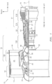
- FIG. 1 is a side cutaway illustration of a geared turbine engine 10.
- This turbine engine 10 extends along an axial centerline 12 between an upstream airflow inlet 14 and a downstream airflow exhaust 16.
- the turbine engine 10 includes a fan section 18, a compressor section 19, a combustor section 20 and a turbine section 21.
- the compressor section 19 includes a low pressure compressor (LPC) section 19A and a high pressure compressor (HPC) section 19B.
- the turbine section 21 includes a high pressure turbine (HPT) section 21A and a low pressure turbine (LPT) section 21B.
- the engine sections 18-21 are arranged sequentially along the centerline 12 within an engine housing 22.
- Each of the engine sections 18-19B, 21A and 21B includes a respective rotor 24-28.
- Each of these rotors 24-28 includes a plurality of rotor blades arranged circumferentially around and connected to one or more respective rotor disks.
- the rotor blades may be formed integral with or mechanically fastened, welded, brazed, adhered and/or otherwise attached to the respective rotor disk(s).
- the fan rotor 24 is connected to a gear train 30, for example, through a fan shaft 32.
- the gear train 30 and the LPC rotor 25 are connected to and driven by the LPT rotor 28 through a low speed shaft 33.
- the HPC rotor 26 is connected to and driven by the HPT rotor 27 through a high speed shaft 34.
- the shafts 32-34 are rotatably supported by a plurality of bearings 36; e.g., rolling element and/or thrust bearings. Each of these bearings 36 is connected to the engine housing 22 by at least one stationary structure such as, for example, an annular support strut.
- the air within the core gas path 38 may be referred to as "core air”.
- the air within the bypass gas path 40 may be referred to as "bypass air”.
- the core air is directed through the engine sections 19-21, and exits the turbine engine 10 through the airflow exhaust 16 to provide forward engine thrust.
- fuel is injected into a combustion chamber 42 and mixed with compressed core air. This fuel-core air mixture is ignited to power the turbine engine 10.
- the bypass air is directed through the bypass gas path 40 and out of the turbine engine 10 through a bypass nozzle 44 to provide additional forward engine thrust. This additional forward engine thrust may account for a majority (e.g., more than 70 percent) of total engine thrust.
- at least some of the bypass air may be directed out of the turbine engine 10 through a thrust reverser to provide reverse engine thrust.
- FIG. 1 represents one possible configuration for an engine 10. Aspects of the disclosure may be applied in connection with other environments, including additional configurations for an engine of an aircraft.
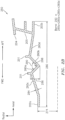
- FIG. 2B an exemplary seal 250 in accordance with aspects of the disclosure is shown.
- the seal 250 includes many of the same components described above in connection with the seal 200 of FIG. 2A . As such, a complete re-description is omitted for the sake of brevity.
- the barrel 203 of the seal 200 is generally linear between the lands 202a and 202b.
- the barrel 203 is oriented substantially axially (e.g., is in the forward and aft directions) as shown in FIG. 2A .
- the seal 250 includes barrel portions/segments 260a and 260b between the edges 201, a barrel segment 260c between the land 202a and the forward edge 201, and a barrel segment 260d between the aft edge 201 and the land 202b as shown in FIG. 2B .
- the barrel segments 260a-260d form a barrel (collectively referred to herein as barrel 260).
- One or more of the barrel segments 260a-260d may be substantially oriented in both the axial and radial reference directions as shown in FIG. 2B , such that the barrel segments 260a-260d, when taken as a whole, are non-linear. As such, the seal 250 may adhere to a non-linear shaped geometry/configuration with respect to the barrel 260.
- the barrel 260 is substantially 'M'-shaped.
- the use of the 'M'-shaped configuration for the seal 250 may enable the seal 250 to "spring" open on one or both ends of the seal when the seal 250 rotates. This spring effect may create a force balance that may reduce overall part stresses relative to conventional designs (e.g., the seal 200).
- the portion of the barrel 260 formed by the segments 260a and 260b between the edges 201 is substantially 'V'-shaped or 'U'-shaped.
- the use of a 'V'-shape may provide for a high degree of clearance.
- the use of a 'U'-shape may make the seal 250 easier to manufacture (relative to the use of a 'V'-shape). Similar remarks apply to the interfaces/transitions between the barrel 260 segments 260c and 260a and between the barrel 260 segments 260b and 260d.
- the barrel 260 may be substantially symmetrical (in terms of its shape/configuration) as shown in FIG. 2B .
- Asymmetrical shapes or configurations for the barrel 260 may be used in some embodiments.
- Such asymmetry may be the result of using a first length for a first of the segments (e.g., segment 260a) that is different from one or more other lengths of the other segments (e.g., segments 260b-260d), by providing the first segment with a different orientation (e.g., a different radial or axial projection) relative to an orientation of one or more of the other segments, etc.
- each of the segments 260a-260d may be of a uniform or constant width/thickness as shown in FIG. 2B .
- one or more of the segments 260a-260d may be of a non-uniform width/thickness.
- one or more of the segments 260a-260d may be tapered in terms of such a width/thickness.
- the seal 250 of FIG. 2B is shown as including a single 'M'-shaped barrel 260.
- the shape of the seal 250 may be expressed as a function of one or more dimensions of the seal 250.
- reference character 274 may reflect an attachment land diameter relative to engine centerline (e.g., centerline 12 of FIG. 1 )
- reference character 280 may reflect a length of the seal 250
- reference character(s) 284 may reflect a thickness of, e.g., one or more of the segments 260a-260d
- reference character 286 may reflect a height of one or more of the segments (e.g., segments 260a or 260b)
- reference character 288 may reflect a radius (e.g., radii that make up peaks and troughs)
- reference character 290 may reflect a (V-)angle.
- the attachment land diameter 274 to length 280 ratio may be within a range of 4:1 to 14:1. It is noted that the attachment lands 202a and 202b might not be at the same diameter (274).
- the attachment land diameter 274 to thickness 284 ratio may be within a range of 240:1 to 500:1 (including any tapering of one or more members). Using a ratio within this range may provide for seal barrel flexibility while still providing for an easy-to-manufacture seal in terms of, e.g., machining thin walled, large diameter parts.
- a length 280 to height 286 ratio may be within a range of 3:1 to 12:1. It is noted that the peak-to-trough pattern associated with height 286 might not be symmetric about any point/plane, the knife edges 201 might not be at the same diameter, and the knife edges 201 may be at any spacing in between the attachment lands 202a and 202b.
- the length 280 to radius 288 ratio may be within a range of 6:1 to 60:1.
- the angle 290 may assume a value within a range of forty degrees to one-hundred twenty degrees.
- the tendency to expand outboard may be prevented/minimized and the OD tensile stress may be reduced/minimized.
- One or more of the stresses described above may be driven by an axial bending field.
- tensile/compressive stresses may be driven by the axial bending field.
- a seal may be used to interface two or more of: a low pressure turbine, a high pressure turbine, a low pressure compressor, a high pressure compressor, etc.
- the lands may be used to provide for such an interface.
- a seal may be configured with a shape or geometry that provides for a reduction in terms of stress (e.g., OD tensile stress).
- stress e.g., OD tensile stress
- aspects of the disclosure may be applied in connection with an engine of an aircraft.
- aspects of the disclosure may be applied in connection with turbine or compressor hardware.
- aspects of the disclosure may be applied in connection with machinery (e.g., rotating machinery) that is configured to seal a fluid between two or more cavities.
Landscapes
- Engineering & Computer Science (AREA)
- General Engineering & Computer Science (AREA)
- Mechanical Engineering (AREA)
- Turbine Rotor Nozzle Sealing (AREA)
Description
- In connection with an aircraft engine, labyrinth seals are used to seal off cavities of higher and lower pressures in areas where there is relative rotational motion. Referring to
FIG. 2A , alabyrinth seal 200 in accordance with the prior art is shown. - The
seal 200 includesknife edges 201 that are used to create the sealing. Theedges 201 rub against a variety of materials and may vary in terms of size, shape, count, angle, orientation, height, and width. - The
seal 200 includesattachment lands land 202a is forward of theland 202b. One or both of thelands - The
seal 200 includessegments barrel 203 herein). Thebarrel 203 extends from the forward attachment land 202-a in the aft direction. - The
seal 200 includes ahammerhead 204. Thehammerhead 204 may have multiple uses but in the context of this disclosure thehammerhead 204 is used to create a(nother) sealing cavity. - The
seal 200 includestabs 205. Thetabs 205 are used to prevent rotation, thereby serving as an anti-rotation mechanism. - The
seal 200 is subjected to stress and large thermal gradients when placed into operational use, leading to component fatigue and a reduction in terms of component lifetime. Such stress may be a result of thelands FIG. 2B ), whereas thebarrel 203 may be composed of a thin mass of material that interfaces to a hot airflow associated with a gas path. The large material mass/discs operate at a cooler temperature than theseal 200, and thus, do not grow as much as theseal 200 in a radially outboard direction (see the radial reference direction superimposed inFIG. 2A ). Consequently, thebarrel 203 may be compelled to deflect in the radial reference direction. The deflections could be large, potentially causing thebarrel 203 to crack. -
EP 2218879 A2 ,WO 2013/001240 A1 andUS 5211535 A disclose features of the preamble of claim 1, andWO 2016/059348 A1 is prior art under Art. 54(3) EPC. - The following presents a simplified summary in order to provide a basic understanding of some aspects of the disclosure. The summary is not an extensive overview of the disclosure. It is neither intended to identify key or critical elements of the disclosure nor to delineate the scope of the disclosure. The following summary merely presents some concepts of the disclosure in a simplified form as a prelude to the description below.
- Aspects of the disclosure are directed to a seal associated with an engine of an aircraft, as claimed in claim 1. In some embodiments, at least one of the segments is of a non-uniform width. In some embodiments, at least one of the segments is tapered in terms of width. In some embodiments, the barrel is substantially symmetrical in terms of shape. In some embodiments, the barrel is substantially asymmetrical in terms of shape. In some embodiments, a first length associated with a first of the segments is different from a second length associated with a second of the segments. In some embodiments, a first orientation associated with a first of the segments is different from a second orientation associated with a second of the segments. In some embodiments, the segments form a plurality of non-linear portions. In some embodiments, at least one of the lands is configured to couple to a disc, and the barrel is configured to interface to a gas path flow. In some embodiments, the seal is configured to seal a fluid between two or more cavities. In some embodiments, the lands are configured to interface a first section of the engine to a second section of the engine. In some embodiments, the seal is configured to interface a low pressure turbine and a high pressure turbine. In some embodiments, the seal is configured to interface a low pressure compressor and a high pressure compressor. In some embodiments, a ratio of a diameter of at least one of the lands to a length of the seal is within a range of 4:1 to 14:1. In some embodiments, a ratio of a diameter of at least one of the lands to a thickness of at least one of the segments is within a range of 240:1 to 500:1. In some embodiments, a ratio of a length of the seal to a height of at least one of the segments is within a range of 3:1 to 12:1. In some embodiments, a ratio of a length of the seal to a radius is within a range of 6:1 to 60:1. In some embodiments, a V-angle associated with the seal assumes a value within a range of forty degrees and one-hundred twenty degrees.
- The present disclosure is illustrated by way of example and not limited in the accompanying figures in which like reference numerals indicate similar elements.
-
FIG. 1 is a side cutaway illustration of a geared turbine engine. -
FIG. 2A illustrates a labyrinth seal in accordance with the prior art. -
FIG. 2B illustrates a labyrinth seal in accordance with aspects of this disclosure. - It is noted that various connections are set forth between elements in the following description and in the drawings (the contents of which are included in this disclosure by way of reference). It is noted that these connections are general and, unless specified otherwise, may be direct or indirect and that this specification is not intended to be limiting in this respect. A coupling between two or more entities may refer to a direct connection or an indirect connection. An indirect connection may incorporate one or more intervening entities.
- In accordance with various aspects of the disclosure, apparatuses, systems and methods are described for providing a seal, such as a labyrinth seal. At least a portion of the seal (a barrel of the seal) includes a plurality of segments, such that when the segments are taken as a whole the barrel is substantially non-linear. The barrel of the seal is substantially shaped as the letter 'M' (in connection with the English language alphabet). The geometry of the seal may enable the seal to "spring" open on one or both ends of the seal when the seal rotates.
- Aspects of the disclosure may be applied in connection with a gas turbine engine.
FIG. 1 is a side cutaway illustration of a gearedturbine engine 10. Thisturbine engine 10 extends along anaxial centerline 12 between anupstream airflow inlet 14 and adownstream airflow exhaust 16. Theturbine engine 10 includes afan section 18, acompressor section 19, acombustor section 20 and aturbine section 21. Thecompressor section 19 includes a low pressure compressor (LPC)section 19A and a high pressure compressor (HPC)section 19B. Theturbine section 21 includes a high pressure turbine (HPT)section 21A and a low pressure turbine (LPT)section 21B. - The engine sections 18-21 are arranged sequentially along the
centerline 12 within anengine housing 22. Each of the engine sections 18-19B, 21A and 21B includes a respective rotor 24-28. Each of these rotors 24-28 includes a plurality of rotor blades arranged circumferentially around and connected to one or more respective rotor disks. The rotor blades, for example, may be formed integral with or mechanically fastened, welded, brazed, adhered and/or otherwise attached to the respective rotor disk(s). - The
fan rotor 24 is connected to agear train 30, for example, through afan shaft 32. Thegear train 30 and theLPC rotor 25 are connected to and driven by theLPT rotor 28 through alow speed shaft 33. TheHPC rotor 26 is connected to and driven by theHPT rotor 27 through ahigh speed shaft 34. The shafts 32-34 are rotatably supported by a plurality ofbearings 36; e.g., rolling element and/or thrust bearings. Each of thesebearings 36 is connected to theengine housing 22 by at least one stationary structure such as, for example, an annular support strut. - During operation, air enters the
turbine engine 10 through theairflow inlet 14, and is directed through thefan section 18 and into acore gas path 38 and abypass gas path 40. The air within thecore gas path 38 may be referred to as "core air". The air within thebypass gas path 40 may be referred to as "bypass air". The core air is directed through the engine sections 19-21, and exits theturbine engine 10 through theairflow exhaust 16 to provide forward engine thrust. Within thecombustor section 20, fuel is injected into acombustion chamber 42 and mixed with compressed core air. This fuel-core air mixture is ignited to power theturbine engine 10. The bypass air is directed through thebypass gas path 40 and out of theturbine engine 10 through abypass nozzle 44 to provide additional forward engine thrust. This additional forward engine thrust may account for a majority (e.g., more than 70 percent) of total engine thrust. Alternatively, at least some of the bypass air may be directed out of theturbine engine 10 through a thrust reverser to provide reverse engine thrust. -
FIG. 1 represents one possible configuration for anengine 10. Aspects of the disclosure may be applied in connection with other environments, including additional configurations for an engine of an aircraft. - Referring to
FIG. 2B , anexemplary seal 250 in accordance with aspects of the disclosure is shown. Theseal 250 includes many of the same components described above in connection with theseal 200 ofFIG. 2A . As such, a complete re-description is omitted for the sake of brevity. - In terms of differences between the
seal 200 and theseal 250, thebarrel 203 of theseal 200 is generally linear between thelands barrel 203 is oriented substantially axially (e.g., is in the forward and aft directions) as shown inFIG. 2A . Conversely, theseal 250 includes barrel portions/segments edges 201, abarrel segment 260c between theland 202a and theforward edge 201, and abarrel segment 260d between theaft edge 201 and theland 202b as shown inFIG. 2B . Thebarrel segments 260a-260d form a barrel (collectively referred to herein as barrel 260). - One or more of the
barrel segments 260a-260d may be substantially oriented in both the axial and radial reference directions as shown inFIG. 2B , such that thebarrel segments 260a-260d, when taken as a whole, are non-linear. As such, theseal 250 may adhere to a non-linear shaped geometry/configuration with respect to thebarrel 260. Thebarrel 260 is substantially 'M'-shaped. - The use of the 'M'-shaped configuration for the
seal 250 may enable theseal 250 to "spring" open on one or both ends of the seal when theseal 250 rotates. This spring effect may create a force balance that may reduce overall part stresses relative to conventional designs (e.g., the seal 200). - The portion of the
barrel 260 formed by thesegments edges 201 is substantially 'V'-shaped or 'U'-shaped. The use of a 'V'-shape may provide for a high degree of clearance. The use of a 'U'-shape may make theseal 250 easier to manufacture (relative to the use of a 'V'-shape). Similar remarks apply to the interfaces/transitions between thebarrel 260segments barrel 260segments - The
barrel 260 may be substantially symmetrical (in terms of its shape/configuration) as shown inFIG. 2B . Asymmetrical shapes or configurations for thebarrel 260 may be used in some embodiments. Such asymmetry may be the result of using a first length for a first of the segments (e.g.,segment 260a) that is different from one or more other lengths of the other segments (e.g.,segments 260b-260d), by providing the first segment with a different orientation (e.g., a different radial or axial projection) relative to an orientation of one or more of the other segments, etc. - In some embodiments, each of the
segments 260a-260d may be of a uniform or constant width/thickness as shown inFIG. 2B . In some embodiments, one or more of thesegments 260a-260d may be of a non-uniform width/thickness. For example, one or more of thesegments 260a-260d may be tapered in terms of such a width/thickness. - The
seal 250 ofFIG. 2B is shown as including a single 'M'-shapedbarrel 260. - The shape of the
seal 250 may be expressed as a function of one or more dimensions of theseal 250. For example,reference character 274 may reflect an attachment land diameter relative to engine centerline (e.g.,centerline 12 ofFIG. 1 ),reference character 280 may reflect a length of theseal 250, reference character(s) 284 may reflect a thickness of, e.g., one or more of thesegments 260a-260d,reference character 286 may reflect a height of one or more of the segments (e.g.,segments reference character 288 may reflect a radius (e.g., radii that make up peaks and troughs), andreference character 290 may reflect a (V-)angle. - In some embodiments, the
attachment land diameter 274 tolength 280 ratio may be within a range of 4:1 to 14:1. It is noted that the attachment lands 202a and 202b might not be at the same diameter (274). - In some embodiments, the
attachment land diameter 274 tothickness 284 ratio may be within a range of 240:1 to 500:1 (including any tapering of one or more members). Using a ratio within this range may provide for seal barrel flexibility while still providing for an easy-to-manufacture seal in terms of, e.g., machining thin walled, large diameter parts. - In some embodiments, a
length 280 toheight 286 ratio may be within a range of 3:1 to 12:1. It is noted that the peak-to-trough pattern associated withheight 286 might not be symmetric about any point/plane, the knife edges 201 might not be at the same diameter, and the knife edges 201 may be at any spacing in between the attachment lands 202a and 202b. - In some embodiments, the
length 280 toradius 288 ratio may be within a range of 6:1 to 60:1. - In some embodiments, the
angle 290 may assume a value within a range of forty degrees to one-hundred twenty degrees. - In a conventional rotating seal design, such as for example in connection with the
seal 200, there may be high tensile stresses on the outer diameter (OD) of theseal 200 and high compressive stresses on the inner diameter (ID) because theseal 200 is trying to bow (radially) outboard at its mid-span. Conversely, in using theseal 250, as rotational speed increases, a portion of theseal 250 or the barrel 260 (e.g., thesegments lands lands - Aspect of the disclosure may be used to interface or seal a first section of an engine to a second section of the engine. For example, in some embodiments a seal may be used to interface two or more of: a low pressure turbine, a high pressure turbine, a low pressure compressor, a high pressure compressor, etc. The lands may be used to provide for such an interface.
- Technical effects and benefits of this disclosure include an enhancement or extension of one or more component or device lifetimes by reducing/minimizing stress concentrations. In some embodiments, a seal may be configured with a shape or geometry that provides for a reduction in terms of stress (e.g., OD tensile stress). Aspects of the disclosure may be applied in connection with an engine of an aircraft. For example, aspects of the disclosure may be applied in connection with turbine or compressor hardware. Aspects of the disclosure may be applied in connection with machinery (e.g., rotating machinery) that is configured to seal a fluid between two or more cavities.
- Aspects of the disclosure have been described in terms of illustrative embodiments thereof. Numerous other embodiments, modifications, and variations within the scope of the appended claims will occur to persons of ordinary skill in the art from a review of this disclosure. For example, one of ordinary skill in the art will appreciate that the steps described in conjunction with the illustrative figures may be performed in other than the recited order, and that one or more steps illustrated may be optional in accordance with aspects of the disclosure.
Claims (14)
- A seal (200) associated with an engine (10) of an aircraft, comprising:a plurality of lands (202a, 202b); anda barrel (260) coupled to the lands (202a, 202b) and formed from a plurality of segments (260a-d),where the segments (260a-d) are coupled to one another such that the barrel (260) is substantially non-linear; wherein the seal further comprises:a plurality of knife edges (201) coupled to the plurality of segments (260a-d);
wherein:a first of the plurality of segments (260a-d) and a second of the plurality of segments (260a-d) between the knife edges (201) is substantially 'V'-shaped; ora first of the plurality of segments (260a-d) and a second of the plurality of segments (260a-d) between the knife edges (201) is substantially 'U'-shaped,characterised in that the barrel (260) is substantially 'M'-shaped,wherein the plurality of segments includes a forward segment (260c) extending to a forward knife edge (201) of the plurality of knife edges (201) and an aft segment (260d) extending to an aft knife edge (201) of the plurality of knife edges (201), wherein the first segment (260a) extends between the forward knife edge (201) and the second segment (260b), and the second segment (260b) extends between the first segment (260a) and the aft knife edge (201), such that the forward segment (260c), first segment (260a), second segment (260b) and aft segment (260d) collectively form the M-shaped barrel (260),wherein the forward segment (260c) extends between the forward knife edge (201) and a forward land (202a) of the plurality of lands, and the aft segment (260d) extends between the aft knife edge (201) and an aft land (202b) of the plurality of lands. - The seal of claim 1, wherein at least one of the segments (260a-d) is of a non-uniform width.
- The seal of claim 1 or 2, wherein at least one of the segments (260a-d) is tapered in terms of width.
- The seal of any preceding claim, wherein the barrel (260) is substantially symmetrical in terms of shape.
- The seal of any of claims 1, 2 or 3, wherein the barrel (260) is substantially asymmetrical in terms of shape.
- The seal of claim 5, wherein a first length or orientation associated with a first of the segments (260a-d) is different from a second length or orientation associated with a second of the segments (260a-d).
- The seal of any preceding claim, wherein the segments (260a-d) form a plurality of non-linear portions.
- The seal of any preceding claim, wherein at least one of the lands is configured to couple to a disc, and wherein the barrel is configured to interface to a gas path flow.
- The seal of any preceding claim, wherein the seal is configured to seal a fluid between two or more cavities.
- The seal of any preceding claim, wherein the lands are configured to interface a first section of the engine to a second section of the engine, and/or
wherein the seal is configured to interface a low pressure turbine and a high pressure turbine, or a low pressure compressor and a high pressure compressor. - The seal of any preceding claim, wherein a ratio of a diameter of at least one of the lands to a length of the seal is within a range of 4:1 to 14:1.
- The seal of any preceding claim, wherein a ratio of a diameter of at least one of the lands to a thickness of at least one of the segments is within a range of 240:1 to 500:1.
- The seal of any preceding claim, wherein a ratio of a length of the seal to a height of at least one of the segments is within a range of 3:1 to 12:1, and/or a ratio of a length of the seal to a radius is within a range of 6:1 to 60:1.
- The seal of any preceding claim, wherein a V-angle associated with the seal assumes a value within a range of forty degrees and one-hundred twenty degrees.
Applications Claiming Priority (1)
| Application Number | Priority Date | Filing Date | Title |
|---|---|---|---|
| US14/684,035 US10502080B2 (en) | 2015-04-10 | 2015-04-10 | Rotating labyrinth M-seal |
Publications (3)
| Publication Number | Publication Date |
|---|---|
| EP3078809A1 EP3078809A1 (en) | 2016-10-12 |
| EP3078809B1 EP3078809B1 (en) | 2019-07-03 |
| EP3078809B2 true EP3078809B2 (en) | 2025-04-30 |
Family
ID=55808366
Family Applications (1)
| Application Number | Title | Priority Date | Filing Date |
|---|---|---|---|
| EP16164679.9A Active EP3078809B2 (en) | 2015-04-10 | 2016-04-11 | Rotating labyrinth m-seal |
Country Status (2)
| Country | Link |
|---|---|
| US (1) | US10502080B2 (en) |
| EP (1) | EP3078809B2 (en) |
Families Citing this family (1)
| Publication number | Priority date | Publication date | Assignee | Title |
|---|---|---|---|---|
| US10634005B2 (en) | 2017-07-13 | 2020-04-28 | United Technologies Corporation | Flow metering and retention system |
Citations (6)
| Publication number | Priority date | Publication date | Assignee | Title |
|---|---|---|---|---|
| US5236302A (en) † | 1991-10-30 | 1993-08-17 | General Electric Company | Turbine disk interstage seal system |
| US5338154A (en) † | 1993-03-17 | 1994-08-16 | General Electric Company | Turbine disk interstage seal axial retaining ring |
| EP1079070A2 (en) † | 1999-08-26 | 2001-02-28 | Asea Brown Boveri Ag | Heatshield for a turbine rotor |
| US6261063B1 (en) † | 1997-06-04 | 2001-07-17 | Mitsubishi Heavy Industries, Ltd. | Seal structure between gas turbine discs |
| EP1512841A2 (en) † | 2003-09-02 | 2005-03-09 | General Electric Company | Methods and apparatus to reduce seal rubbing within gas turbine engines |
| US20100158676A1 (en) † | 2008-12-22 | 2010-06-24 | Rolls-Royce Plc | Composite component |
Family Cites Families (31)
| Publication number | Priority date | Publication date | Assignee | Title |
|---|---|---|---|---|
| US835836A (en) * | 1906-02-27 | 1906-11-13 | Richard Schulz | Labyrinth packing for rotary machines. |
| US1708044A (en) * | 1923-09-12 | 1929-04-09 | Westinghouse Electric & Mfg Co | Labyrinth-gland packing |
| US3257119A (en) * | 1965-01-21 | 1966-06-21 | Goodrich Co B F | Fluid pressure seal assembly in which increasing pressure decreases breakout force |
| US3572728A (en) | 1968-06-17 | 1971-03-30 | Gen Eelctric Co | Rotary seal |
| US3824030A (en) | 1973-07-30 | 1974-07-16 | Curtiss Wright Corp | Diaphragm and labyrinth seal assembly for gas turbines |
| US4103899A (en) | 1975-10-01 | 1978-08-01 | United Technologies Corporation | Rotary seal with pressurized air directed at fluid approaching the seal |
| US4526508A (en) | 1982-09-29 | 1985-07-02 | United Technologies Corporation | Rotor assembly for a gas turbine engine |
| US5143383A (en) * | 1984-06-04 | 1992-09-01 | General Electric Company | Stepped tooth rotating labyrinth seal |
| US5211535A (en) | 1991-12-30 | 1993-05-18 | General Electric Company | Labyrinth seals for gas turbine engine |
| US5960625A (en) | 1998-08-21 | 1999-10-05 | Zdvorak, Sr.; Edward H. | Constant volume combustion turbine with plurality flow turbine wheels |
| US6698439B2 (en) | 2000-07-03 | 2004-03-02 | Tokyo Electron Limited | Processing apparatus with sealing mechanism |
| US6682077B1 (en) | 2001-02-14 | 2004-01-27 | Guy Louis Letourneau | Labyrinth seal for disc turbine |
| US6581940B2 (en) * | 2001-07-30 | 2003-06-24 | S&B Technical Products, Inc. | Concrete manhole connector gasket |
| EP1508672A1 (en) | 2003-08-21 | 2005-02-23 | Siemens Aktiengesellschaft | Segmented fastening ring for a turbine |
| FR2867223B1 (en) * | 2004-03-03 | 2006-07-28 | Snecma Moteurs | TURBOMACHINE AS FOR EXAMPLE A TURBOJET AIRCRAFT |
| US8167547B2 (en) * | 2007-03-05 | 2012-05-01 | United Technologies Corporation | Gas turbine engine with canted pocket and canted knife edge seal |
| WO2009009189A2 (en) * | 2007-04-20 | 2009-01-15 | General Electric Company | Transporting particulate material |
| US8235656B2 (en) * | 2009-02-13 | 2012-08-07 | General Electric Company | Catenary turbine seal systems |
| CN101804905B (en) | 2009-02-18 | 2011-08-03 | 孙明昭 | Support roller |
| DE202009010047U1 (en) | 2009-07-23 | 2010-12-23 | Gapi Technische Produkte Gmbh | Rotary oil joint |
| JP5451544B2 (en) | 2009-10-22 | 2014-03-26 | Ntn株式会社 | Bearing with sensor |
| GB201012719D0 (en) * | 2010-07-29 | 2010-09-15 | Rolls Royce Plc | Labyrinth seal |
| FR2977274B1 (en) | 2011-06-30 | 2013-07-12 | Snecma | LABYRINTH SEAL SEAL FOR TURBINE OF A GAS TURBINE ENGINE |
| FR2978793B1 (en) | 2011-08-03 | 2015-12-04 | Snecma | ROTOR OF TURBINE FOR A TURBOMACHINE |
| WO2013132055A1 (en) * | 2012-03-08 | 2013-09-12 | Siemens Aktiengesellschaft | Radial turbomachine having a swirl-reducing element |
| EP2642081A1 (en) | 2012-03-21 | 2013-09-25 | Alstom Technology Ltd | Labyrinth seal for turbines |
| EP2938836B1 (en) | 2012-12-29 | 2020-02-05 | United Technologies Corporation | Seal support disk and assembly |
| GB2516931B (en) * | 2013-08-07 | 2019-12-25 | Intelligent Energy Ltd | Interface seal for a fuel cartridge |
| CN107002690B (en) | 2014-10-15 | 2021-03-02 | 赛峰航空器发动机 | Rotating assembly for a turbine engine including a self-supporting rotor casing |
| GB201419766D0 (en) * | 2014-11-06 | 2014-12-24 | Rolls Royce Plc | A sealing arrangement for a gas turbine engine |
| US10107126B2 (en) * | 2015-08-19 | 2018-10-23 | United Technologies Corporation | Non-contact seal assembly for rotational equipment |
-
2015
- 2015-04-10 US US14/684,035 patent/US10502080B2/en active Active
-
2016
- 2016-04-11 EP EP16164679.9A patent/EP3078809B2/en active Active
Patent Citations (6)
| Publication number | Priority date | Publication date | Assignee | Title |
|---|---|---|---|---|
| US5236302A (en) † | 1991-10-30 | 1993-08-17 | General Electric Company | Turbine disk interstage seal system |
| US5338154A (en) † | 1993-03-17 | 1994-08-16 | General Electric Company | Turbine disk interstage seal axial retaining ring |
| US6261063B1 (en) † | 1997-06-04 | 2001-07-17 | Mitsubishi Heavy Industries, Ltd. | Seal structure between gas turbine discs |
| EP1079070A2 (en) † | 1999-08-26 | 2001-02-28 | Asea Brown Boveri Ag | Heatshield for a turbine rotor |
| EP1512841A2 (en) † | 2003-09-02 | 2005-03-09 | General Electric Company | Methods and apparatus to reduce seal rubbing within gas turbine engines |
| US20100158676A1 (en) † | 2008-12-22 | 2010-06-24 | Rolls-Royce Plc | Composite component |
Also Published As
| Publication number | Publication date |
|---|---|
| EP3078809A1 (en) | 2016-10-12 |
| US20160298481A1 (en) | 2016-10-13 |
| US10502080B2 (en) | 2019-12-10 |
| EP3078809B1 (en) | 2019-07-03 |
Similar Documents
| Publication | Publication Date | Title |
|---|---|---|
| EP3102794B1 (en) | Blade outer air seal mount | |
| EP2412924B1 (en) | A disk spacer for a gas engine turbine and a method for providing a rotor assembly | |
| EP3239471B1 (en) | Floating, non-contact seal with rounded edge | |
| EP2949874B1 (en) | Dual walled seal assembly | |
| EP3447344B1 (en) | Hydrostatic non-contact seal with dual material | |
| EP3418610B1 (en) | Hydrostatic non-contact seal with weight reduction pocket | |
| US10370996B2 (en) | Floating, non-contact seal with offset build clearance for load imbalance | |
| EP3093445B1 (en) | Gas turbine vane and method of forming | |
| EP3290755A1 (en) | Floating, non-contact seal with at least three beams | |
| EP3450680B1 (en) | Turbine rotor disk | |
| US10598035B2 (en) | Intershaft sealing systems for gas turbine engines and methods for assembling the same | |
| EP3450690B1 (en) | Turbine rotor | |
| EP3486433A1 (en) | Labyrinth seal with different tooth heights | |
| EP3409885B1 (en) | Deflection spring seal | |
| US12215588B2 (en) | Seal assembly for a gas turbine engine | |
| EP3730745B1 (en) | Rotating leaf spring seal | |
| EP2957722B1 (en) | Rotor for a gas turbine engine | |
| US11268402B2 (en) | Blade outer air seal cooling fin | |
| EP3078809B2 (en) | Rotating labyrinth m-seal | |
| EP3192969B1 (en) | Gas turbine engine component with optimized leading edge geometry | |
| EP3203023A1 (en) | Gas turbine engine with a cooling fluid path | |
| CN118499085A (en) | Seal member support system for a gas turbine engine | |
| US20230265762A1 (en) | Turbine engine with a floating interstage seal | |
| EP3290637B1 (en) | Tandem rotor blades with cooling features | |
| US11674400B2 (en) | Gas turbine engine nozzles |
Legal Events
| Date | Code | Title | Description |
|---|---|---|---|
| PUAI | Public reference made under article 153(3) epc to a published international application that has entered the european phase |
Free format text: ORIGINAL CODE: 0009012 |
|
| AK | Designated contracting states |
Kind code of ref document: A1 Designated state(s): AL AT BE BG CH CY CZ DE DK EE ES FI FR GB GR HR HU IE IS IT LI LT LU LV MC MK MT NL NO PL PT RO RS SE SI SK SM TR |
|
| AX | Request for extension of the european patent |
Extension state: BA ME |
|
| RAP1 | Party data changed (applicant data changed or rights of an application transferred) |
Owner name: UNITED TECHNOLOGIES CORPORATION |
|
| STAA | Information on the status of an ep patent application or granted ep patent |
Free format text: STATUS: REQUEST FOR EXAMINATION WAS MADE |
|
| 17P | Request for examination filed |
Effective date: 20170412 |
|
| RBV | Designated contracting states (corrected) |
Designated state(s): AL AT BE BG CH CY CZ DE DK EE ES FI FR GB GR HR HU IE IS IT LI LT LU LV MC MK MT NL NO PL PT RO RS SE SI SK SM TR |
|
| STAA | Information on the status of an ep patent application or granted ep patent |
Free format text: STATUS: EXAMINATION IS IN PROGRESS |
|
| 17Q | First examination report despatched |
Effective date: 20180531 |
|
| GRAP | Despatch of communication of intention to grant a patent |
Free format text: ORIGINAL CODE: EPIDOSNIGR1 |
|
| STAA | Information on the status of an ep patent application or granted ep patent |
Free format text: STATUS: GRANT OF PATENT IS INTENDED |
|
| INTG | Intention to grant announced |
Effective date: 20190114 |
|
| GRAS | Grant fee paid |
Free format text: ORIGINAL CODE: EPIDOSNIGR3 |
|
| GRAA | (expected) grant |
Free format text: ORIGINAL CODE: 0009210 |
|
| STAA | Information on the status of an ep patent application or granted ep patent |
Free format text: STATUS: THE PATENT HAS BEEN GRANTED |
|
| AK | Designated contracting states |
Kind code of ref document: B1 Designated state(s): AL AT BE BG CH CY CZ DE DK EE ES FI FR GB GR HR HU IE IS IT LI LT LU LV MC MK MT NL NO PL PT RO RS SE SI SK SM TR |
|
| REG | Reference to a national code |
Ref country code: GB Ref legal event code: FG4D |
|
| REG | Reference to a national code |
Ref country code: CH Ref legal event code: EP Ref country code: AT Ref legal event code: REF Ref document number: 1151231 Country of ref document: AT Kind code of ref document: T Effective date: 20190715 |
|
| REG | Reference to a national code |
Ref country code: DE Ref legal event code: R096 Ref document number: 602016016127 Country of ref document: DE |
|
| REG | Reference to a national code |
Ref country code: IE Ref legal event code: FG4D |
|
| REG | Reference to a national code |
Ref country code: NL Ref legal event code: MP Effective date: 20190703 |
|
| REG | Reference to a national code |
Ref country code: LT Ref legal event code: MG4D |
|
| REG | Reference to a national code |
Ref country code: AT Ref legal event code: MK05 Ref document number: 1151231 Country of ref document: AT Kind code of ref document: T Effective date: 20190703 |
|
| PG25 | Lapsed in a contracting state [announced via postgrant information from national office to epo] |
Ref country code: BG Free format text: LAPSE BECAUSE OF FAILURE TO SUBMIT A TRANSLATION OF THE DESCRIPTION OR TO PAY THE FEE WITHIN THE PRESCRIBED TIME-LIMIT Effective date: 20191003 Ref country code: SE Free format text: LAPSE BECAUSE OF FAILURE TO SUBMIT A TRANSLATION OF THE DESCRIPTION OR TO PAY THE FEE WITHIN THE PRESCRIBED TIME-LIMIT Effective date: 20190703 Ref country code: AT Free format text: LAPSE BECAUSE OF FAILURE TO SUBMIT A TRANSLATION OF THE DESCRIPTION OR TO PAY THE FEE WITHIN THE PRESCRIBED TIME-LIMIT Effective date: 20190703 Ref country code: NO Free format text: LAPSE BECAUSE OF FAILURE TO SUBMIT A TRANSLATION OF THE DESCRIPTION OR TO PAY THE FEE WITHIN THE PRESCRIBED TIME-LIMIT Effective date: 20191003 Ref country code: NL Free format text: LAPSE BECAUSE OF FAILURE TO SUBMIT A TRANSLATION OF THE DESCRIPTION OR TO PAY THE FEE WITHIN THE PRESCRIBED TIME-LIMIT Effective date: 20190703 Ref country code: LT Free format text: LAPSE BECAUSE OF FAILURE TO SUBMIT A TRANSLATION OF THE DESCRIPTION OR TO PAY THE FEE WITHIN THE PRESCRIBED TIME-LIMIT Effective date: 20190703 Ref country code: HR Free format text: LAPSE BECAUSE OF FAILURE TO SUBMIT A TRANSLATION OF THE DESCRIPTION OR TO PAY THE FEE WITHIN THE PRESCRIBED TIME-LIMIT Effective date: 20190703 Ref country code: CZ Free format text: LAPSE BECAUSE OF FAILURE TO SUBMIT A TRANSLATION OF THE DESCRIPTION OR TO PAY THE FEE WITHIN THE PRESCRIBED TIME-LIMIT Effective date: 20190703 Ref country code: FI Free format text: LAPSE BECAUSE OF FAILURE TO SUBMIT A TRANSLATION OF THE DESCRIPTION OR TO PAY THE FEE WITHIN THE PRESCRIBED TIME-LIMIT Effective date: 20190703 Ref country code: PT Free format text: LAPSE BECAUSE OF FAILURE TO SUBMIT A TRANSLATION OF THE DESCRIPTION OR TO PAY THE FEE WITHIN THE PRESCRIBED TIME-LIMIT Effective date: 20191104 |
|
| PG25 | Lapsed in a contracting state [announced via postgrant information from national office to epo] |
Ref country code: GR Free format text: LAPSE BECAUSE OF FAILURE TO SUBMIT A TRANSLATION OF THE DESCRIPTION OR TO PAY THE FEE WITHIN THE PRESCRIBED TIME-LIMIT Effective date: 20191004 Ref country code: ES Free format text: LAPSE BECAUSE OF FAILURE TO SUBMIT A TRANSLATION OF THE DESCRIPTION OR TO PAY THE FEE WITHIN THE PRESCRIBED TIME-LIMIT Effective date: 20190703 Ref country code: AL Free format text: LAPSE BECAUSE OF FAILURE TO SUBMIT A TRANSLATION OF THE DESCRIPTION OR TO PAY THE FEE WITHIN THE PRESCRIBED TIME-LIMIT Effective date: 20190703 Ref country code: LV Free format text: LAPSE BECAUSE OF FAILURE TO SUBMIT A TRANSLATION OF THE DESCRIPTION OR TO PAY THE FEE WITHIN THE PRESCRIBED TIME-LIMIT Effective date: 20190703 Ref country code: RS Free format text: LAPSE BECAUSE OF FAILURE TO SUBMIT A TRANSLATION OF THE DESCRIPTION OR TO PAY THE FEE WITHIN THE PRESCRIBED TIME-LIMIT Effective date: 20190703 Ref country code: IS Free format text: LAPSE BECAUSE OF FAILURE TO SUBMIT A TRANSLATION OF THE DESCRIPTION OR TO PAY THE FEE WITHIN THE PRESCRIBED TIME-LIMIT Effective date: 20191103 |
|
| PG25 | Lapsed in a contracting state [announced via postgrant information from national office to epo] |
Ref country code: TR Free format text: LAPSE BECAUSE OF FAILURE TO SUBMIT A TRANSLATION OF THE DESCRIPTION OR TO PAY THE FEE WITHIN THE PRESCRIBED TIME-LIMIT Effective date: 20190703 |
|
| REG | Reference to a national code |
Ref country code: DE Ref legal event code: R026 Ref document number: 602016016127 Country of ref document: DE |
|
| PLBI | Opposition filed |
Free format text: ORIGINAL CODE: 0009260 |
|
| PG25 | Lapsed in a contracting state [announced via postgrant information from national office to epo] |
Ref country code: RO Free format text: LAPSE BECAUSE OF FAILURE TO SUBMIT A TRANSLATION OF THE DESCRIPTION OR TO PAY THE FEE WITHIN THE PRESCRIBED TIME-LIMIT Effective date: 20190703 Ref country code: EE Free format text: LAPSE BECAUSE OF FAILURE TO SUBMIT A TRANSLATION OF THE DESCRIPTION OR TO PAY THE FEE WITHIN THE PRESCRIBED TIME-LIMIT Effective date: 20190703 Ref country code: PL Free format text: LAPSE BECAUSE OF FAILURE TO SUBMIT A TRANSLATION OF THE DESCRIPTION OR TO PAY THE FEE WITHIN THE PRESCRIBED TIME-LIMIT Effective date: 20190703 Ref country code: DK Free format text: LAPSE BECAUSE OF FAILURE TO SUBMIT A TRANSLATION OF THE DESCRIPTION OR TO PAY THE FEE WITHIN THE PRESCRIBED TIME-LIMIT Effective date: 20190703 Ref country code: IT Free format text: LAPSE BECAUSE OF FAILURE TO SUBMIT A TRANSLATION OF THE DESCRIPTION OR TO PAY THE FEE WITHIN THE PRESCRIBED TIME-LIMIT Effective date: 20190703 |
|
| 26 | Opposition filed |
Opponent name: SAFRAN AIRCRAFT ENGINES Effective date: 20200401 |
|
| PG25 | Lapsed in a contracting state [announced via postgrant information from national office to epo] |
Ref country code: SM Free format text: LAPSE BECAUSE OF FAILURE TO SUBMIT A TRANSLATION OF THE DESCRIPTION OR TO PAY THE FEE WITHIN THE PRESCRIBED TIME-LIMIT Effective date: 20190703 Ref country code: IS Free format text: LAPSE BECAUSE OF FAILURE TO SUBMIT A TRANSLATION OF THE DESCRIPTION OR TO PAY THE FEE WITHIN THE PRESCRIBED TIME-LIMIT Effective date: 20200224 Ref country code: SK Free format text: LAPSE BECAUSE OF FAILURE TO SUBMIT A TRANSLATION OF THE DESCRIPTION OR TO PAY THE FEE WITHIN THE PRESCRIBED TIME-LIMIT Effective date: 20190703 |
|
| PLAX | Notice of opposition and request to file observation + time limit sent |
Free format text: ORIGINAL CODE: EPIDOSNOBS2 |
|
| PG2D | Information on lapse in contracting state deleted |
Ref country code: IS |
|
| PG25 | Lapsed in a contracting state [announced via postgrant information from national office to epo] |
Ref country code: SI Free format text: LAPSE BECAUSE OF FAILURE TO SUBMIT A TRANSLATION OF THE DESCRIPTION OR TO PAY THE FEE WITHIN THE PRESCRIBED TIME-LIMIT Effective date: 20190703 |
|
| PLBB | Reply of patent proprietor to notice(s) of opposition received |
Free format text: ORIGINAL CODE: EPIDOSNOBS3 |
|
| PLAY | Examination report in opposition despatched + time limit |
Free format text: ORIGINAL CODE: EPIDOSNORE2 |
|
| PG25 | Lapsed in a contracting state [announced via postgrant information from national office to epo] |
Ref country code: MC Free format text: LAPSE BECAUSE OF FAILURE TO SUBMIT A TRANSLATION OF THE DESCRIPTION OR TO PAY THE FEE WITHIN THE PRESCRIBED TIME-LIMIT Effective date: 20190703 |
|
| REG | Reference to a national code |
Ref country code: CH Ref legal event code: PL |
|
| RAP2 | Party data changed (patent owner data changed or rights of a patent transferred) |
Owner name: RAYTHEON TECHNOLOGIES CORPORATION |
|
| PG25 | Lapsed in a contracting state [announced via postgrant information from national office to epo] |
Ref country code: LU Free format text: LAPSE BECAUSE OF NON-PAYMENT OF DUE FEES Effective date: 20200411 Ref country code: LI Free format text: LAPSE BECAUSE OF NON-PAYMENT OF DUE FEES Effective date: 20200430 Ref country code: CH Free format text: LAPSE BECAUSE OF NON-PAYMENT OF DUE FEES Effective date: 20200430 |
|
| REG | Reference to a national code |
Ref country code: BE Ref legal event code: MM Effective date: 20200430 |
|
| PLBC | Reply to examination report in opposition received |
Free format text: ORIGINAL CODE: EPIDOSNORE3 |
|
| PG25 | Lapsed in a contracting state [announced via postgrant information from national office to epo] |
Ref country code: BE Free format text: LAPSE BECAUSE OF NON-PAYMENT OF DUE FEES Effective date: 20200430 |
|
| PG25 | Lapsed in a contracting state [announced via postgrant information from national office to epo] |
Ref country code: IE Free format text: LAPSE BECAUSE OF NON-PAYMENT OF DUE FEES Effective date: 20200411 |
|
| REG | Reference to a national code |
Ref country code: CH Ref legal event code: PK Free format text: TITEL |
|
| APBM | Appeal reference recorded |
Free format text: ORIGINAL CODE: EPIDOSNREFNO |
|
| APBP | Date of receipt of notice of appeal recorded |
Free format text: ORIGINAL CODE: EPIDOSNNOA2O |
|
| APAH | Appeal reference modified |
Free format text: ORIGINAL CODE: EPIDOSCREFNO |
|
| PG25 | Lapsed in a contracting state [announced via postgrant information from national office to epo] |
Ref country code: MT Free format text: LAPSE BECAUSE OF FAILURE TO SUBMIT A TRANSLATION OF THE DESCRIPTION OR TO PAY THE FEE WITHIN THE PRESCRIBED TIME-LIMIT Effective date: 20190703 Ref country code: CY Free format text: LAPSE BECAUSE OF FAILURE TO SUBMIT A TRANSLATION OF THE DESCRIPTION OR TO PAY THE FEE WITHIN THE PRESCRIBED TIME-LIMIT Effective date: 20190703 |
|
| PG25 | Lapsed in a contracting state [announced via postgrant information from national office to epo] |
Ref country code: MK Free format text: LAPSE BECAUSE OF FAILURE TO SUBMIT A TRANSLATION OF THE DESCRIPTION OR TO PAY THE FEE WITHIN THE PRESCRIBED TIME-LIMIT Effective date: 20190703 |
|
| APBQ | Date of receipt of statement of grounds of appeal recorded |
Free format text: ORIGINAL CODE: EPIDOSNNOA3O |
|
| REG | Reference to a national code |
Ref country code: DE Ref legal event code: R081 Ref document number: 602016016127 Country of ref document: DE Owner name: RAYTHEON TECHNOLOGIES CORPORATION (N.D.GES.D.S, US Free format text: FORMER OWNER: UNITED TECHNOLOGIES CORPORATION, FARMINGTON, CONN., US Ref country code: DE Ref legal event code: R081 Ref document number: 602016016127 Country of ref document: DE Owner name: RTX CORPORATION (N.D.GES.D. STAATES DELAWARE),, US Free format text: FORMER OWNER: UNITED TECHNOLOGIES CORPORATION, FARMINGTON, CONN., US |
|
| P01 | Opt-out of the competence of the unified patent court (upc) registered |
Effective date: 20230520 |
|
| RAP4 | Party data changed (patent owner data changed or rights of a patent transferred) |
Owner name: RTX CORPORATION |
|
| APBU | Appeal procedure closed |
Free format text: ORIGINAL CODE: EPIDOSNNOA9O |
|
| PUAH | Patent maintained in amended form |
Free format text: ORIGINAL CODE: 0009272 |
|
| STAA | Information on the status of an ep patent application or granted ep patent |
Free format text: STATUS: PATENT MAINTAINED AS AMENDED |
|
| 27A | Patent maintained in amended form |
Effective date: 20250430 |
|
| AK | Designated contracting states |
Kind code of ref document: B2 Designated state(s): AL AT BE BG CH CY CZ DE DK EE ES FI FR GB GR HR HU IE IS IT LI LT LU LV MC MK MT NL NO PL PT RO RS SE SI SK SM TR |
|
| REG | Reference to a national code |
Ref country code: DE Ref legal event code: R102 Ref document number: 602016016127 Country of ref document: DE |
|
| PGFP | Annual fee paid to national office [announced via postgrant information from national office to epo] |
Ref country code: DE Payment date: 20250319 Year of fee payment: 10 |
|
| REG | Reference to a national code |
Ref country code: DE Ref legal event code: R081 Ref document number: 602016016127 Country of ref document: DE Owner name: RTX CORPORATION (N.D.GES.D. STAATES DELAWARE),, US Free format text: FORMER OWNER: RAYTHEON TECHNOLOGIES CORPORATION (N.D.GES.D.STAATES DELAWARE), ARLINGTON, VA, US |
|
| PGFP | Annual fee paid to national office [announced via postgrant information from national office to epo] |
Ref country code: GB Payment date: 20260319 Year of fee payment: 11 |
|
| PGFP | Annual fee paid to national office [announced via postgrant information from national office to epo] |
Ref country code: FR Payment date: 20260319 Year of fee payment: 11 |