EP3078617A1 - Transporting apparatus - Google Patents
Transporting apparatus Download PDFInfo
- Publication number
- EP3078617A1 EP3078617A1 EP15162524.1A EP15162524A EP3078617A1 EP 3078617 A1 EP3078617 A1 EP 3078617A1 EP 15162524 A EP15162524 A EP 15162524A EP 3078617 A1 EP3078617 A1 EP 3078617A1
- Authority
- EP
- European Patent Office
- Prior art keywords
- guiding surface
- roller
- rollers
- couple
- rotation
- Prior art date
- Legal status (The legal status is an assumption and is not a legal conclusion. Google has not performed a legal analysis and makes no representation as to the accuracy of the status listed.)
- Granted
Links
Images
Classifications
-
- B—PERFORMING OPERATIONS; TRANSPORTING
- B65—CONVEYING; PACKING; STORING; HANDLING THIN OR FILAMENTARY MATERIAL
- B65G—TRANSPORT OR STORAGE DEVICES, e.g. CONVEYORS FOR LOADING OR TIPPING, SHOP CONVEYOR SYSTEMS OR PNEUMATIC TUBE CONVEYORS
- B65G54/00—Non-mechanical conveyors not otherwise provided for
- B65G54/02—Non-mechanical conveyors not otherwise provided for electrostatic, electric, or magnetic
-
- B—PERFORMING OPERATIONS; TRANSPORTING
- B61—RAILWAYS
- B61B—RAILWAY SYSTEMS; EQUIPMENT THEREFOR NOT OTHERWISE PROVIDED FOR
- B61B3/00—Elevated railway systems with suspended vehicles
- B61B3/02—Elevated railway systems with suspended vehicles with self-propelled vehicles
-
- B—PERFORMING OPERATIONS; TRANSPORTING
- B65—CONVEYING; PACKING; STORING; HANDLING THIN OR FILAMENTARY MATERIAL
- B65B—MACHINES, APPARATUS OR DEVICES FOR, OR METHODS OF, PACKAGING ARTICLES OR MATERIALS; UNPACKING
- B65B65/00—Details peculiar to packaging machines and not otherwise provided for; Arrangements of such details
-
- B—PERFORMING OPERATIONS; TRANSPORTING
- B65—CONVEYING; PACKING; STORING; HANDLING THIN OR FILAMENTARY MATERIAL
- B65G—TRANSPORT OR STORAGE DEVICES, e.g. CONVEYORS FOR LOADING OR TIPPING, SHOP CONVEYOR SYSTEMS OR PNEUMATIC TUBE CONVEYORS
- B65G35/00—Mechanical conveyors not otherwise provided for
-
- B—PERFORMING OPERATIONS; TRANSPORTING
- B65—CONVEYING; PACKING; STORING; HANDLING THIN OR FILAMENTARY MATERIAL
- B65G—TRANSPORT OR STORAGE DEVICES, e.g. CONVEYORS FOR LOADING OR TIPPING, SHOP CONVEYOR SYSTEMS OR PNEUMATIC TUBE CONVEYORS
- B65G2201/00—Indexing codes relating to handling devices, e.g. conveyors, characterised by the type of product or load being conveyed or handled
- B65G2201/02—Articles
-
- B—PERFORMING OPERATIONS; TRANSPORTING
- B65—CONVEYING; PACKING; STORING; HANDLING THIN OR FILAMENTARY MATERIAL
- B65G—TRANSPORT OR STORAGE DEVICES, e.g. CONVEYORS FOR LOADING OR TIPPING, SHOP CONVEYOR SYSTEMS OR PNEUMATIC TUBE CONVEYORS
- B65G2812/00—Indexing codes relating to the kind or type of conveyors
- B65G2812/99—Conveyor systems not otherwise provided for
Definitions
- the invention relates to a transporting apparatus for conveying an object.
- the object may be a device, or a tool, of a machine, in particular a packaging machine.
- Transporting apparatus based on linear motor technology are known, which comprise a track that houses a stator armature formed by a plurality of individually-excitable solenoids, and a plurality of movable elements or carts that house respective permanent magnets and are independently moved along the track by individually controlling the solenoids.
- the track comprises guide elements and the movable elements comprise wheels slideable along the guide elements of the track.
- the position of the movable element with respect to the track has to be extremely precise, in order to assure that the machine works in a proper way.
- a drawback of the known transporting apparatus is that there might be an excessive play, or clearance, between the wheels and the guide elements, leading to a mispositioning of the movable elements with respect to the track. In case the transporting apparatus are used in a machine, this may cause a mispositioning of the device, or tool, supported by the movable elements.
- An object of the invention is to improve the known transporting apparatus.
- Another object of the invention is to provide a transporting apparatus that has high stiffness and extremely limited play, or clearance.
- Another object of the invention is to provide a transporting apparatus that, when used in a machine, is able to carry a tool of the machine and position the tool in a very accurate and precise way.
- a transporting apparatus 1 comprising a track 2 and a plurality of movable elements 3 movable along the track 2.
- the track 2 houses a stator armature formed by a plurality of individually-excitable solenoids 101 and the movable elements 3 house permanent magnets 102.
- the movable elements 3 are independently movable along the track 2 by individually controlling the solenoids 101.
- the track 2 houses the permanent magnets and the movable elements 3 house the individually-excitable solenoids.
- the movable elements 3 are arranged for carrying an object.
- the above-mentioned object may be a device, or a tool, that carries out a certain operation in the machine.
- the device, or tool in case of a packaging machine for manufacturing packages by folding, filling and sealing a web of packaging material, can be a forming element for forming a package, or a moulding element for moulding plastics on the packaging material to obtain an opening device of the package.
- the track 2 comprises a guiding member 4 on which the movable elements 3 are movable.
- the guiding member 4 comprises a first plate 5a projecting from a first side 60 of a frame 6 of the track 2.
- the guiding member 4 also comprises a second plate 5b projecting from a second side 61, opposite to the first side 60, of the frame 6.
- the guiding member 4 has a first linear branch 7 and a second linear branch 8.
- the first linear branch 7 and the second linear branch 8 are substantially parallel to each other.
- first linear branch 7 and the second linear branch 8 are arranged in a vertical plane.
- the guiding member 4 further comprises a first curved branch 9 and a second curved branch (not shown) interposed between the first linear branch 7 and the second linear branch 8.
- the first curved branch 9 and the second curved branch are opposite to each other. In this way, the guiding member 4 has a substantially oval longitudinal cross section.
- the movable elements 3 comprise a supporting body 14 arranged for supporting the above-mentioned object, i.e. the device, or tool, in the case of a machine.
- the movable elements 3 further comprise a first couple of rollers 15, a further first couple of rollers 16, a second couple of rollers 17, a further second couple of rollers 18, a third couple of rollers 19 and a further third couple of rollers 20 that are rotatably connected to the supporting body 14 and slidably coupled with the guiding member 4.
- the guiding member 4 comprises a first guiding surface 11a and a further first guiding surface 11b facing towards the supporting body 14, a second guiding surface 12a and a further second guiding surface 12b facing away from the supporting body 14, and a third guiding surface 13a arranged transversally with respect to the first guiding surface 11a and the second guiding surface 12a, and a further third guiding surface 13b arranged transversally with respect to the further first guiding surface 11b and the further second guiding surface 12b.
- the first guiding surface 11a and the further first guiding surface 11b are mutually aligned.
- the second guiding surface 12a and the further second guiding surface 12b are mutually aligned.
- the second guiding surface 12a is arranged on the opposite side of the supporting body 14 with respect to the first guiding surface 11a.
- the further second guiding surface 12b is arranged on the opposite side of the supporting body 14 with respect to the further first guiding surface 11b.
- the first guiding surface 11a and the further first guiding surface 11b are parallel to the second guiding surface 12a and the further second guiding surface 12b.
- the third guiding surface 13a is perpendicular to the first guiding surface 11a and to the second guiding surface 12a.
- the further third guiding surface 13b is perpendicular to the further first guiding surface 11b and to the further second guiding surface 12b.
- the third guiding surface 13a is parallel to the further third guiding surface 13b.
- the first plate 5a comprises the first guiding surface 11a, the second guiding surface 12a and the third guiding surface 13a.
- the second plate 5b comprises the further first guiding surface 11b, the further second guiding surface 12b and the further third guiding surface 13b.
- the first couple of rollers 15 slides along the first guiding surface 11a.
- the further first couple of rollers 16 slides along the further first guiding surface 11b.
- the second couple of rollers 17 slides along the second guiding surface 12a.
- the further second couple of rollers 18 slides along the further second guiding surface 12b.
- the third couple of rollers 19 slides along the third guiding surface 13a.
- the further third couple of rollers 20 slides along the further third guiding surface 13b.
- the first couple of rollers 15 comprises a first roller 21 and a second roller 22.
- the further first couple of rollers 16 comprises a third roller 23 and a fourth roller 24.
- the second couple of rollers 17 comprises a fifth roller 25 and a sixth roller 26.
- the further second couple of rollers 18 comprises a seventh roller 27 and an eighth roller 28.
- the third couple of rollers 19 comprises a ninth roller 29 and a tenth roller 30.
- the further third couple of rollers 20 comprises an eleventh roller 31 and a twelfth roller 32.
- the movable elements 3 slide on the track 2 along an advancing direction A.
- the movable elements 3 move on the track 2 along an axis Z, parallel to the advancing direction A.
- the first roller 21, the second roller 22, the third roller 23, the fourth roller 24, the fifth roller 25, the sixth roller 26, the seventh roller 27 and the eighth roller 28 prevents the movable element 3 from moving along a further axis Y perpendicular to axis Z and also perpendicular to the first guiding surface 11a, the further first guiding surface 11b, the second guiding surface 12a and the further second guiding surface 12b.
- the ninth roller 29, the tenth roller 30, the eleventh roller 31 and the twelfth roller 32 prevent the movable element 3 from moving along a still further axis X perpendicular to axis Z and also perpendicular to the third guiding surface 13a and the further third guiding surface 13b.
- Axis Z, further axis Y and still further axis X are perpendicular to each other.
- Axis Z, further axis Y and still further axis X are to be intended as integral with the movable element 3, as the movable element 3 moves along the track 4.
- the second roller 22 and the fifth roller 25, and the fourth roller 24 and the seventh roller 27, prevent the movable elements 3 from rotating around still further axis X, in a clockwise direction.
- the first roller 21 and the sixth roller 26, and the third roller 23 and the eighth roller 28, prevent the movable elements 3 from rotating around still further axis X, in a counter-clockwise direction.
- the tenth roller 30 and the eleventh roller 31 prevent the movable elements 3 from rotating around further axis Y, in a clockwise direction.
- the ninth roller 29 and the twelfth roller 32 prevent the movable elements 3 from rotating around further axis Y, in a counter-clockwise direction.
- the first roller 21 and the second roller 22, and the seventh roller 27 and the eighth roller 28, prevent the movable elements 3 from rotating around axis Z, in a clockwise direction.
- the fifth roller 25 and the sixth roller 26, and the third roller 23 and the fourth roller 24, prevent the movable elements 3 from rotating around axis Z, in a counter-clockwise direction.
- the rotation axes of the rollers of the first couple of rollers 15, i.e. the rotation axes of the first roller 21 and the second roller 22, are parallel to still further axis X and perpendicular to the third guiding surface 13a and the further third guiding surface 13b.
- the rotation axes of the rollers of the further first couple of rollers 16, i.e. the rotation axes of the third roller 23 and the fourth roller 24, are parallel to still further axis X and perpendicular to the third guiding surface 13a and the further first guiding surface 13b.
- the rotation axes of the rollers of the second couple of rollers 17, i.e. the rotation axes of the fifth roller 25 and the sixth roller 26, are parallel to still further axis X and perpendicular to the third guiding surface 13a and the further third guiding surface 13b.
- the rotation axes of the rollers of the further second couple of rollers 18, i.e. the rotation axes of the seventh roller 27 and the eighth roller 28, are parallel to still further axis X and perpendicular to the third guiding surface 13a and the further second guiding surface 13b.
- the rotation axes of the rollers of the third couple of rollers 19, i.e. the rotation axes of the ninth roller 29 and the tenth roller 30, are parallel to further axis Y and perpendicular to the first guiding surface 11a, the further first guiding surface 11b, the second guiding surface 12a and the further second guiding surface 12b.
- the rotation axes of the rollers of the further third couple of rollers 20, i.e. the rotation axes of the eleventh roller 31 and the twelfth roller 32, are parallel to further axis Y and perpendicular to the first guiding surface 11a, the further first guiding surface 11b, the second guiding surface 12a and the further second guiding surface 12b.
- the first roller 21, the second roller 22, the third roller 23, the fourth roller 24, the fifth roller 25, the sixth roller 26, the seventh roller 27, the eighth roller 28, the ninth roller 29, the tenth roller 30, the eleventh roller 31 and the twelfth roller 32 are mounted on the supporting body 14 by means of rotation units 33, each supporting a group of rollers 34.
- Each group of rollers 34 comprises three rollers, a roller belonging to the first couple of rollers 15 or to the further first couple of rollers 16, a further roller belonging to the second couple of rollers 17 or, respectively, to the further second couple of rollers 18 and a still further roller belonging to the third couple of rollers 19 or, respectively, to the further third couple of rollers 20.
- the supporting body 14 comprises a front part 35 substantially extending in a plane defined by axis Z and still further axis X and a first side part 36a and a second side part 36b protruding from opposite sides of the front part 35 and each substantially extending in a plane defined by axis Z and further axis Y.
- the front part 35 is arranged to support the above-mentioned object.
- Each rotation unit 33 comprises a rotation element 37 that is rotatably coupled to the supporting body 14, in particular to the first side part 36a or to the second side part 36b, and is rotatable around a rotation axis parallel to the still further axis X, i.e. perpendicular to the third guiding surface 13a and to the further third guiding surface 13b.
- Each movable element 3 comprises four rotation units 33, in particular a first rotation unit 33a (shown in Figure 3 ) and a second rotation unit (not shown) rotatably coupled to the first side part 36a, and a third rotation unit 33c (shown in Figures 2 and 3 ) and a fourth rotation unit 33d (shown in Figure 2 ) rotatably coupled to the second side part 36b.
- the first rotation unit 33a comprises the first roller 21, the fifth roller 25 and the ninth roller 29.
- the second rotation unit comprises the second roller 22, the sixth roller 26 and the tenth roller 30.
- the third rotation unit 33c comprises the third roller 23, the seventh roller 27 and the eleventh roller 31.
- the fourth rotation unit 33d comprises the fourth roller 24, the eighth roller 28 and the twelfth roller 32.
- roller 41 corresponds to the fifth roller 25
- further roller 42 corresponds to the first roller 21
- still further roller 43 corresponds to ninth roller 29.
- roller 41 corresponds to the sixth roller 26
- further roller 42 corresponds to the second roller 22
- still further roller 43 corresponds to tenth roller 30.
- roller 41 corresponds to the third roller 23
- further roller 42 corresponds to the seventh roller 27
- still further roller 43 corresponds to eleventh roller 31.
- roller 41 corresponds to the fourth roller 24
- roller 42 corresponds to the eighth roller 28
- still further roller 43 corresponds to twelfth roller 32.
- the rotation element 37 comprises a shaft portion 38 received in a hole 39 of the first side part 36a, or the second side part 36b.
- a bearing 40 is interposed between the shaft portion 38 and the first side part 36a, or the second side part 36b.
- the rotation element 37 further comprises a bracket portion 44 that comprises a pin 45 that rotatably supports the roller 41 and a further pin 46 that rotatably supports the further roller 42.
- the rotation element 37 further comprises a seat 47 that receives the still further roller 43.
- the rotation element 37 comprises a still further pin 48 protruding into the seat 47 and rotatably supporting the still further roller 43.
- the axes of rotation of the roller 41 and the further roller 42 are aligned on a line L.
- the axes of rotation of the roller 41, the further roller 42 and the still further roller 43 are arranged in a plane P.
- the minimum distance between the roller 41 and the further roller 42 is less than the width of the first plate 5a, or the second plate 5b, measured along further axis Y. In other words, the minimum distance between the roller 41 and the further roller 42 is less than the distance between the first guiding surface 11a and the second guiding surface 12a or, respectively, the further first guiding surface 11b and the further second guiding surface 12b.
- roller 41 and the further roller 42 are mounted on the guiding member with interference, so as to avoid play, or clearance, between the movable elements 3 and the track 2.
- the movable elements 3 are moved on the track 2 independently from each other by individually controlling the corresponding solenoids.
- the first roller 21, the second roller 22, the third roller 23, the fourth roller 24, the fifth roller 25, the sixth roller 26, the seventh roller 27, the eighth roller 28, the ninth roller 29, the tenth roller 30, the eleventh roller 31 and the twelfth roller 32 precisely guide the movable elements 3 in the advancing direction A, i.e. along axis Z and prevent any other movement of the movable elements 3 along still further axis X and further axis Y, and around still further axis X, further axis Y and axis Z.
- the line L is always kept perpendicular to the first guiding surface 11a and the second guiding surface 12a or, respectively, to the further first guiding surface 11b and the further second guiding surface 12b.
- the line L is always so oriented as to pass through the centre of curvature of the first curved branch 9, or - respectively - the second curved branch.
- the transporting apparatus 1 has high stiffness, and the movable elements 3 may carry rather heavy objects without compromising a good positioning of the objects.
- the above-mentioned devices, or tools can be precisely positioned also in case they are cantilevered to the movable elements 3 and, therefore, the movable elements 3 are subjected to significant loads.
- the movable elements 3 are properly guided both along the first linear branch 7 and second linear branch 8, and the first curved branch 9 and second curved branch.
Landscapes
- Engineering & Computer Science (AREA)
- Mechanical Engineering (AREA)
- Transportation (AREA)
- Rollers For Roller Conveyors For Transfer (AREA)
- Bearings For Parts Moving Linearly (AREA)
- Non-Mechanical Conveyors (AREA)
- Auxiliary Devices For And Details Of Packaging Control (AREA)
- Basic Packing Technique (AREA)
- Machine Tool Units (AREA)
Abstract
Description
- The invention relates to a transporting apparatus for conveying an object. The object may be a device, or a tool, of a machine, in particular a packaging machine.
- Transporting apparatus based on linear motor technology are known, which comprise a track that houses a stator armature formed by a plurality of individually-excitable solenoids, and a plurality of movable elements or carts that house respective permanent magnets and are independently moved along the track by individually controlling the solenoids.
- The track comprises guide elements and the movable elements comprise wheels slideable along the guide elements of the track.
- In case the movable element supports a device, or a tool, of a machine, the position of the movable element with respect to the track has to be extremely precise, in order to assure that the machine works in a proper way.
- A drawback of the known transporting apparatus is that there might be an excessive play, or clearance, between the wheels and the guide elements, leading to a mispositioning of the movable elements with respect to the track. In case the transporting apparatus are used in a machine, this may cause a mispositioning of the device, or tool, supported by the movable elements.
- An object of the invention is to improve the known transporting apparatus.
- Another object of the invention is to provide a transporting apparatus that has high stiffness and extremely limited play, or clearance.
- Another object of the invention is to provide a transporting apparatus that, when used in a machine, is able to carry a tool of the machine and position the tool in a very accurate and precise way.
- According to the invention there is provided a transporting apparatus as claimed in
claim 1. - A preferred, non-limiting embodiment of the invention will be described by way of example with reference to the accompanying drawings, in which:
-
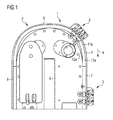
Figure 1 is a side view, with parts removed for clarity, of an apparatus according to the invention; -
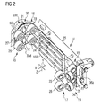
Figure 2 is a perspective side view, with parts removed for clarity, of a movable element of the apparatus ofFigure 1 ; -
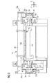
Figure 3 is a transversal section, with parts removed for clarity, of the movable element ofFigure 2 ; -
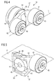
Figure 4 is a perspective view of a rotation element that supports rollers of the movable element ofFigures 2 and3 ; -
Figure 5 is a partly sectioned perspective view of the rotation element ofFigure 4 . - With reference to
Figures 1 to 5 , there is shown a transportingapparatus 1 comprising atrack 2 and a plurality ofmovable elements 3 movable along thetrack 2. - The
track 2 houses a stator armature formed by a plurality of individually-excitable solenoids 101 and themovable elements 3 housepermanent magnets 102. - The
movable elements 3 are independently movable along thetrack 2 by individually controlling thesolenoids 101. - In another embodiment, the
track 2 houses the permanent magnets and themovable elements 3 house the individually-excitable solenoids. - The
movable elements 3 are arranged for carrying an object. In case the transporting apparatus is used in a machine, in particular a packaging machine, the above-mentioned object may be a device, or a tool, that carries out a certain operation in the machine. - In particular, in case of a packaging machine for manufacturing packages by folding, filling and sealing a web of packaging material, the device, or tool, can be a forming element for forming a package, or a moulding element for moulding plastics on the packaging material to obtain an opening device of the package.
- The
track 2 comprises a guidingmember 4 on which themovable elements 3 are movable. - The guiding
member 4 comprises afirst plate 5a projecting from afirst side 60 of aframe 6 of thetrack 2. - The guiding
member 4 also comprises asecond plate 5b projecting from asecond side 61, opposite to thefirst side 60, of theframe 6. - The guiding
member 4 has a firstlinear branch 7 and a second linear branch 8. The firstlinear branch 7 and the second linear branch 8 are substantially parallel to each other. - In the embodiment shown the first
linear branch 7 and the second linear branch 8 are arranged in a vertical plane. - The guiding
member 4 further comprises a firstcurved branch 9 and a second curved branch (not shown) interposed between the firstlinear branch 7 and the second linear branch 8. The firstcurved branch 9 and the second curved branch are opposite to each other. In this way, the guidingmember 4 has a substantially oval longitudinal cross section. - The
movable elements 3 comprise a supportingbody 14 arranged for supporting the above-mentioned object, i.e. the device, or tool, in the case of a machine. - The
movable elements 3 further comprise a first couple ofrollers 15, a further first couple ofrollers 16, a second couple ofrollers 17, a further second couple ofrollers 18, a third couple ofrollers 19 and a further third couple ofrollers 20 that are rotatably connected to the supportingbody 14 and slidably coupled with the guidingmember 4. - The guiding
member 4 comprises a first guidingsurface 11a and a further first guidingsurface 11b facing towards the supportingbody 14, a second guidingsurface 12a and a further second guiding surface 12b facing away from the supportingbody 14, and a third guidingsurface 13a arranged transversally with respect to the first guidingsurface 11a and the second guidingsurface 12a, and a further third guidingsurface 13b arranged transversally with respect to the further first guidingsurface 11b and the further second guiding surface 12b. - The first guiding
surface 11a and the further first guidingsurface 11b are mutually aligned. - The second guiding
surface 12a and the further second guiding surface 12b are mutually aligned. - The second guiding
surface 12a is arranged on the opposite side of the supportingbody 14 with respect to the first guidingsurface 11a. - The further second guiding surface 12b is arranged on the opposite side of the supporting
body 14 with respect to the further first guidingsurface 11b. - The first guiding
surface 11a and the further first guidingsurface 11b are parallel to the second guidingsurface 12a and the further second guiding surface 12b. - The third guiding
surface 13a is perpendicular to the first guidingsurface 11a and to the second guidingsurface 12a. - The further third guiding
surface 13b is perpendicular to the further first guidingsurface 11b and to the further second guiding surface 12b. - The third guiding
surface 13a is parallel to the further third guidingsurface 13b. - The
first plate 5a comprises the first guidingsurface 11a, the second guidingsurface 12a and the third guidingsurface 13a. - The
second plate 5b comprises the further first guidingsurface 11b, the further second guiding surface 12b and the further third guidingsurface 13b. - The first couple of
rollers 15 slides along the first guidingsurface 11a. - The further first couple of
rollers 16 slides along the further first guidingsurface 11b. - The second couple of
rollers 17 slides along the second guidingsurface 12a. - The further second couple of
rollers 18 slides along the further second guiding surface 12b. - The third couple of
rollers 19 slides along the third guidingsurface 13a. - The further third couple of
rollers 20 slides along the further third guidingsurface 13b. - The first couple of
rollers 15 comprises afirst roller 21 and asecond roller 22. - The further first couple of
rollers 16 comprises athird roller 23 and afourth roller 24. - The second couple of
rollers 17 comprises afifth roller 25 and asixth roller 26. - The further second couple of
rollers 18 comprises aseventh roller 27 and aneighth roller 28. - The third couple of
rollers 19 comprises aninth roller 29 and a tenth roller 30. - The further third couple of
rollers 20 comprises aneleventh roller 31 and atwelfth roller 32. - The
movable elements 3 slide on thetrack 2 along an advancing direction A. - The
movable elements 3 move on thetrack 2 along an axis Z, parallel to the advancing direction A. - The
first roller 21, thesecond roller 22, thethird roller 23, thefourth roller 24, thefifth roller 25, thesixth roller 26, theseventh roller 27 and theeighth roller 28 prevents themovable element 3 from moving along a further axis Y perpendicular to axis Z and also perpendicular to the first guidingsurface 11a, the further first guidingsurface 11b, the second guidingsurface 12a and the further second guiding surface 12b. - The
ninth roller 29, the tenth roller 30, theeleventh roller 31 and thetwelfth roller 32 prevent themovable element 3 from moving along a still further axis X perpendicular to axis Z and also perpendicular to the third guidingsurface 13a and the further third guidingsurface 13b. - Axis Z, further axis Y and still further axis X are perpendicular to each other.
- Axis Z, further axis Y and still further axis X are to be intended as integral with the
movable element 3, as themovable element 3 moves along thetrack 4. - The
second roller 22 and thefifth roller 25, and thefourth roller 24 and theseventh roller 27, prevent themovable elements 3 from rotating around still further axis X, in a clockwise direction. - The
first roller 21 and thesixth roller 26, and thethird roller 23 and theeighth roller 28, prevent themovable elements 3 from rotating around still further axis X, in a counter-clockwise direction. - The tenth roller 30 and the
eleventh roller 31 prevent themovable elements 3 from rotating around further axis Y, in a clockwise direction. - The
ninth roller 29 and thetwelfth roller 32 prevent themovable elements 3 from rotating around further axis Y, in a counter-clockwise direction. - The
first roller 21 and thesecond roller 22, and theseventh roller 27 and theeighth roller 28, prevent themovable elements 3 from rotating around axis Z, in a clockwise direction. - The
fifth roller 25 and thesixth roller 26, and thethird roller 23 and thefourth roller 24, prevent themovable elements 3 from rotating around axis Z, in a counter-clockwise direction. - The rotation axes of the rollers of the first couple of
rollers 15, i.e. the rotation axes of thefirst roller 21 and thesecond roller 22, are parallel to still further axis X and perpendicular to thethird guiding surface 13a and the furtherthird guiding surface 13b. - The rotation axes of the rollers of the further first couple of
rollers 16, i.e. the rotation axes of thethird roller 23 and thefourth roller 24, are parallel to still further axis X and perpendicular to thethird guiding surface 13a and the further first guidingsurface 13b. - The rotation axes of the rollers of the second couple of
rollers 17, i.e. the rotation axes of thefifth roller 25 and thesixth roller 26, are parallel to still further axis X and perpendicular to thethird guiding surface 13a and the furtherthird guiding surface 13b. - The rotation axes of the rollers of the further second couple of
rollers 18, i.e. the rotation axes of theseventh roller 27 and theeighth roller 28, are parallel to still further axis X and perpendicular to thethird guiding surface 13a and the furthersecond guiding surface 13b. - The rotation axes of the rollers of the third couple of
rollers 19, i.e. the rotation axes of theninth roller 29 and the tenth roller 30, are parallel to further axis Y and perpendicular to thefirst guiding surface 11a, the further first guidingsurface 11b, thesecond guiding surface 12a and the further second guiding surface 12b. - The rotation axes of the rollers of the further third couple of
rollers 20, i.e. the rotation axes of theeleventh roller 31 and thetwelfth roller 32, are parallel to further axis Y and perpendicular to thefirst guiding surface 11a, the further first guidingsurface 11b, thesecond guiding surface 12a and the further second guiding surface 12b. - The
first roller 21, thesecond roller 22, thethird roller 23, thefourth roller 24, thefifth roller 25, thesixth roller 26, theseventh roller 27, theeighth roller 28, theninth roller 29, the tenth roller 30, theeleventh roller 31 and thetwelfth roller 32 are mounted on the supportingbody 14 by means ofrotation units 33, each supporting a group ofrollers 34. - Each group of
rollers 34 comprises three rollers, a roller belonging to the first couple ofrollers 15 or to the further first couple ofrollers 16, a further roller belonging to the second couple ofrollers 17 or, respectively, to the further second couple ofrollers 18 and a still further roller belonging to the third couple ofrollers 19 or, respectively, to the further third couple ofrollers 20. - The supporting
body 14 comprises afront part 35 substantially extending in a plane defined by axis Z and still further axis X and afirst side part 36a and asecond side part 36b protruding from opposite sides of thefront part 35 and each substantially extending in a plane defined by axis Z and further axis Y. Thefront part 35 is arranged to support the above-mentioned object. - Each
rotation unit 33 comprises arotation element 37 that is rotatably coupled to the supportingbody 14, in particular to thefirst side part 36a or to thesecond side part 36b, and is rotatable around a rotation axis parallel to the still further axis X, i.e. perpendicular to thethird guiding surface 13a and to the furtherthird guiding surface 13b. - Each
movable element 3 comprises fourrotation units 33, in particular afirst rotation unit 33a (shown inFigure 3 ) and a second rotation unit (not shown) rotatably coupled to thefirst side part 36a, and athird rotation unit 33c (shown inFigures 2 and3 ) and afourth rotation unit 33d (shown inFigure 2 ) rotatably coupled to thesecond side part 36b. - The
first rotation unit 33a comprises thefirst roller 21, thefifth roller 25 and theninth roller 29. - The second rotation unit comprises the
second roller 22, thesixth roller 26 and the tenth roller 30. - The
third rotation unit 33c comprises thethird roller 23, theseventh roller 27 and theeleventh roller 31. - The
fourth rotation unit 33d comprises thefourth roller 24, theeighth roller 28 and thetwelfth roller 32. - In the next passages of the description, since the
first rotation unit 33a, the second rotation unit, thethird rotation unit 33c and thefourth rotation unit 33d are identical to each other, reference will be made to only onerotation element 37, and the three rollers of the corresponding group ofrollers 34 will be generally referred to - for sake of simplicity and conciseness - asroller 41,further roller 42 and stillfurther roller 43. - It is to be intended that in the
first rotation 41 corresponds to theunit 33a rollerfifth roller 25,further roller 42 corresponds to thefirst roller 21 and stillfurther roller 43 corresponds toninth roller 29. - Similarly, it is to be intended that in the second
rotation unit roller 41 corresponds to thesixth roller 26,further roller 42 corresponds to thesecond roller 22 and stillfurther roller 43 corresponds to tenth roller 30. - Similarly, it is to be intended that in the
third rotation 41 corresponds to theunit 33c rollerthird roller 23,further roller 42 corresponds to theseventh roller 27 and stillfurther roller 43 corresponds toeleventh roller 31. - Similarly, it is to be intended that in the
fourth rotation 41 corresponds to theunit 33d rollerfourth roller 24,further roller 42 corresponds to theeighth roller 28 and stillfurther roller 43 corresponds totwelfth roller 32. - The
rotation element 37 comprises ashaft portion 38 received in ahole 39 of thefirst side part 36a, or thesecond side part 36b. Abearing 40 is interposed between theshaft portion 38 and thefirst side part 36a, or thesecond side part 36b. - The
rotation element 37 further comprises abracket portion 44 that comprises apin 45 that rotatably supports theroller 41 and afurther pin 46 that rotatably supports thefurther roller 42. - The
rotation element 37 further comprises aseat 47 that receives the stillfurther roller 43. - The
rotation element 37 comprises a stillfurther pin 48 protruding into theseat 47 and rotatably supporting the stillfurther roller 43. - The axes of rotation of the
roller 41 and thefurther roller 42 are aligned on a line L. - The axes of rotation of the
roller 41, thefurther roller 42 and the stillfurther roller 43 are arranged in a plane P. - The minimum distance between the
roller 41 and thefurther roller 42 is less than the width of thefirst plate 5a, or thesecond plate 5b, measured along further axis Y. In other words, the minimum distance between theroller 41 and thefurther roller 42 is less than the distance between thefirst guiding surface 11a and thesecond guiding surface 12a or, respectively, the further first guidingsurface 11b and the further second guiding surface 12b. - In this way, the
roller 41 and thefurther roller 42 are mounted on the guiding member with interference, so as to avoid play, or clearance, between themovable elements 3 and thetrack 2. - During operation, the
movable elements 3 are moved on thetrack 2 independently from each other by individually controlling the corresponding solenoids. - The
first roller 21, thesecond roller 22, thethird roller 23, thefourth roller 24, thefifth roller 25, thesixth roller 26, theseventh roller 27, theeighth roller 28, theninth roller 29, the tenth roller 30, theeleventh roller 31 and thetwelfth roller 32 precisely guide themovable elements 3 in the advancing direction A, i.e. along axis Z and prevent any other movement of themovable elements 3 along still further axis X and further axis Y, and around still further axis X, further axis Y and axis Z. - Due to the
rotation elements 37, the line L is always kept perpendicular to thefirst guiding surface 11a and thesecond guiding surface 12a or, respectively, to the further first guidingsurface 11b and the further second guiding surface 12b. In particular, when themovable elements 3 move along the firstcurved branch 9, or the second curved branch, the line L is always so oriented as to pass through the centre of curvature of the firstcurved branch 9, or - respectively - the second curved branch. - Owing to the invention it is possible to obtain a transporting
apparatus 1 in which themovable elements 3 are substantially not allowed any movement apart from the one along the advancing direction A. - In addition, due to the position of the first couple of
rollers 15, the further first couple ofrollers 16, the second couple ofrollers 17, the further second couple ofrollers 18, the third couple ofrollers 19 and the further third couple ofrollers 20 the transportingapparatus 1 has high stiffness, and themovable elements 3 may carry rather heavy objects without compromising a good positioning of the objects. In particular, in the case of a machine, the above-mentioned devices, or tools, can be precisely positioned also in case they are cantilevered to themovable elements 3 and, therefore, themovable elements 3 are subjected to significant loads. - In addition, due to the
rotation elements 37, themovable elements 3 are properly guided both along the firstlinear branch 7 and second linear branch 8, and the firstcurved branch 9 and second curved branch. - Clearly, changes may be made to the transporting apparatus as described and illustrated herein without, however, departing from the scope of the present invention as defined in the accompanying claims.
Claims (16)
- Transporting apparatus, comprising a track (2) and at least one movable element (3) movable along said track (2), said movable element (3) comprising a supporting body (14), said track (2) comprising a first guiding surface (11a) and a further first guiding surface (11b) facing towards said supporting body (14), a second guiding surface (12a) and a further second guiding surface (12b) facing away from said supporting body (14), and a third guiding surface (13a) arranged transversally to said first guiding surface (11a) and said second guiding surface (12a) and a further third guiding surface (13b) arranged transversally to said further first guiding surface (11b) and said further second guiding surface (12b), wherein said movable element (3) comprises a first couple of rollers (15) slidably coupled to said first guiding surface (11a), a further first couple of rollers (16) slidably coupled to said further first guiding surface (11b), a second couple of rollers (17) slidably coupled to said second guiding surface (12a), a further second couple of rollers (18) slidably coupled to said further second guiding surface (12b), a third couple of rollers (19) slidably coupled to said third guiding surface (13a) and a further third couple of rollers (20) slidably coupled to said further third guiding surface (13b).
- Transporting apparatus according to claim 1, wherein said first guiding surface (11a) and said further first guiding surface (11b) are mutually aligned, wherein said second guiding surface (12a) and said further second guiding surface (12b) are mutually aligned and parallel to said first guiding surface (11a) and said further first guiding surface (11b), and wherein said third guiding surface (13a) is perpendicular to said first guiding surface (11a) and said second guiding surface (12a), and said further third guiding surface (13b) is perpendicular to said further first guiding surface (11b) and said further second guiding surface (12b).
- Transporting apparatus according to claim 1, or 2, wherein the rotation axes of the rollers of said first couple of rollers (15) are perpendicular to said third guiding surface (13a) and said further third guiding surface (13b), wherein the rotation axes of the rollers of said further first couple of rollers (16) are and perpendicular to said third guiding surface (13a) and said further first guiding surface (13b), wherein the rotation axes of the rollers of said second couple of rollers (17) are perpendicular to said third guiding surface (13a) and said further third guiding surface (13b), wherein the rotation axes of the rollers of said further second couple of rollers (18) are perpendicular to said third guiding surface (13a) and said further second guiding surface (13b), wherein the rotation axes of the rollers of said third couple of rollers (19) are perpendicular to said first guiding surface (11a), said further first guiding surface (11b), said second guiding surface (12a) and said further second guiding surface (12b), and wherein the rotation axes of the rollers of said further third couple of rollers (20) are perpendicular to said first guiding surface (11a), said further first guiding surface (11b), said second guiding surface (12a) and said further second guiding surface (12b).
- Transporting apparatus according to any one of the preceding claims, wherein said second guiding surface (12a) is arranged on the opposite side of said supporting body (14) with respect to said first guiding surface (11a), and wherein said further second guiding surface (12b) is arranged on the opposite side of said supporting body (14) with respect to said further first guiding surface (11b).
- Transporting apparatus according to any one of the preceding claims, and further comprising four rotation units (33) each supporting a group of three rollers (34), each group of three rollers (34) comprising a roller (41; 42) belonging to said first couple of rollers (15) or to said further first couple of rollers (16), a further roller (42; 41) belonging to said second couple of rollers (17) or, respectively, to said further second couple of rollers (18) and a still further roller (43) belonging to said third couple of rollers (19) or, respectively, to said further third couple of rollers (20).
- Transporting apparatus according to claim 5, wherein said rotation unit (33) comprises a rotation element (37) that is rotatably coupled to said supporting body (14) and is rotatable around a rotation axis perpendicular to said third guiding surface (13a) and said further third guiding surface (13b).
- Transporting apparatus according to claim 6, wherein said rotation element (37) comprises a bracket portion (44) provided with a pin (45; 46) that rotatably supports said roller (41; 42) and a further pin (46; 45) that rotatably supports said further roller (42; 41).
- Transporting apparatus according to claim 6, or 7, wherein said rotation element (37) further comprises a seat (47) that receives said still further roller (43) and a still further pin (48) protruding into said seat (47) and rotatably supporting said still further roller (43).
- Transporting apparatus according to any one of claims 5 to 8, wherein the axes of rotation of said roller (41; 42) and said further roller (42; 41) are aligned on a line (L) that, when said movable element (3) moves along said track (2), remains perpendicular to said first guiding surface (11a), said further first guiding surface (11b), said second guiding surface (12a) and further second guiding surface (12b).
- Transporting apparatus according to any one of claims 5 to 9, wherein the axes of rotation of said roller (41; 42), said further roller (42; 41) and said still further roller (43) are arranged in a plane (P).
- Transporting apparatus according to any one of the preceding claims, wherein said first couple of rollers (15) comprises a first roller (21) and a second roller (22), said further first couple of rollers (16) comprises a third roller (23) and a fourth roller (24), said second couple of rollers (17) comprises a fifth roller (25) and a sixth roller (26), said further second couple of rollers (18) comprises a seventh roller (27) and an eighth roller (28), said third couple of rollers (19) comprises a ninth roller (29) and a tenth roller (30) and said further third couple of rollers (20) comprises an eleventh roller (31) and a twelfth roller (32).
- Transporting apparatus according to claim 11 as appended to any one of claims 5 to 10, wherein said movable element (3) comprises four rotation units (33), a first rotation unit (33a) comprising said first roller (21), said fifth roller (25) and said ninth roller (29), a second rotation unit comprising said second roller (22), said sixth roller (26) and said tenth roller (30), a third rotation unit (33c) comprising said third roller (23), said seventh roller (27) and said eleventh roller (31), a fourth rotation unit (33d) comprising said fourth roller (24), said eighth roller (28) and said twelfth roller (32).
- Transporting apparatus according to claim 12, wherein said supporting body (14) comprises a front part (35), and a first side part (36a) and a second side part (36b) protruding from opposite sides of said front part (35), said first rotation unit (33a) and said second rotation unit being rotatably coupled to said first side part (36a), and said third rotation unit (33c) and said fourth rotation unit (33d) being rotatably coupled to said second side part (36b).
- Transporting apparatus according to any one of the preceding claims, wherein said track (2) comprises a guiding member (4), said guiding member (4) being provided, at a first side thereof, with said first guiding surface (11a), said second guiding surface (12a) and said third guiding surface (13a), said guiding member (4) being further provided, at a second side thereof, opposite to said first side, with said further first guiding surface (11b), said further second guiding surface (12b) and said further third guiding surface (13b), said guiding member (4) having a first linear branch (7), a second linear branch (8), a first curved branch (9) and a second curved branch, said first curved branch (9) and said second curved branch being interposed between said first linear branch (7) and said second linear branch (8).
- Transporting apparatus according to any one of the preceding claims, and comprising a plurality of movable element (3), said track (2) housing individually-excitable solenoids and said movable elements (3) housing permanent magnets (3), or said movable elements (3) housing individually-excitable solenoids and said track (2) housing permanent magnets, said movable elements (3) being independently movable along said track (2) by individually controlling said solenoids.
- Packaging machine for producing packages from a packaging material, said packaging machine comprising a plurality of tools arranged for carrying out an operation on said packaging material, said packaging machine further comprising a transporting apparatus according to claim 15, wherein each of said movable elements (3) supports one of said tools.
Priority Applications (11)
| Application Number | Priority Date | Filing Date | Title |
|---|---|---|---|
| ES15162524.1T ES2682936T3 (en) | 2015-04-07 | 2015-04-07 | Transport device |
| EP15162524.1A EP3078617B1 (en) | 2015-04-07 | 2015-04-07 | Transporting apparatus |
| US15/558,665 US10189655B2 (en) | 2015-04-07 | 2016-03-24 | Transporting apparatus |
| MX2017012823A MX383046B (en) | 2015-04-07 | 2016-03-24 | TRANSPORTATION DEVICE. |
| KR1020177026997A KR101858916B1 (en) | 2015-04-07 | 2016-03-24 | Transportation device |
| BR112017020330-8A BR112017020330B1 (en) | 2015-04-07 | 2016-03-24 | Conveyor apparatus and wrapping machine |
| CN201680014053.6A CN107406205B (en) | 2015-04-07 | 2016-03-24 | transport device |
| RU2017134694A RU2666084C1 (en) | 2015-04-07 | 2016-03-24 | Transporting device |
| PCT/EP2016/056501 WO2016162217A1 (en) | 2015-04-07 | 2016-03-24 | Transporting apparatus |
| JP2017552861A JP6644084B2 (en) | 2015-04-07 | 2016-03-24 | Transfer device |
| JP2019175011A JP6794519B2 (en) | 2015-04-07 | 2019-09-26 | Transport device |
Applications Claiming Priority (1)
| Application Number | Priority Date | Filing Date | Title |
|---|---|---|---|
| EP15162524.1A EP3078617B1 (en) | 2015-04-07 | 2015-04-07 | Transporting apparatus |
Publications (2)
| Publication Number | Publication Date |
|---|---|
| EP3078617A1 true EP3078617A1 (en) | 2016-10-12 |
| EP3078617B1 EP3078617B1 (en) | 2018-05-23 |
Family
ID=52823497
Family Applications (1)
| Application Number | Title | Priority Date | Filing Date |
|---|---|---|---|
| EP15162524.1A Active EP3078617B1 (en) | 2015-04-07 | 2015-04-07 | Transporting apparatus |
Country Status (10)
| Country | Link |
|---|---|
| US (1) | US10189655B2 (en) |
| EP (1) | EP3078617B1 (en) |
| JP (2) | JP6644084B2 (en) |
| KR (1) | KR101858916B1 (en) |
| CN (1) | CN107406205B (en) |
| BR (1) | BR112017020330B1 (en) |
| ES (1) | ES2682936T3 (en) |
| MX (1) | MX383046B (en) |
| RU (1) | RU2666084C1 (en) |
| WO (1) | WO2016162217A1 (en) |
Cited By (3)
| Publication number | Priority date | Publication date | Assignee | Title |
|---|---|---|---|---|
| WO2018137796A1 (en) * | 2017-01-27 | 2018-08-02 | Krones Ag | Rotors for long-stator-linear-motor systems, having a low-wear mounting arrangement |
| US20190241074A1 (en) * | 2018-02-08 | 2019-08-08 | Rockwell Automation Technologies, Inc. | Dual Rail Track System for Industrial Control |
| WO2020053167A1 (en) * | 2018-09-12 | 2020-03-19 | Weiss Gmbh | Transport trolley |
Families Citing this family (6)
| Publication number | Priority date | Publication date | Assignee | Title |
|---|---|---|---|---|
| ES2682936T3 (en) * | 2015-04-07 | 2018-09-24 | Tetra Laval Holdings & Finance Sa | Transport device |
| DE102015226139A1 (en) * | 2015-12-21 | 2017-06-22 | Krones Ag | Linear transport system with minimal transport division |
| CN108539949B (en) * | 2017-03-01 | 2020-07-31 | 台达电子工业股份有限公司 | Moving magnetic type transfer platform |
| JP1604980S (en) | 2017-03-20 | 2018-05-28 | ||
| US11878828B2 (en) * | 2018-05-11 | 2024-01-23 | Tetra Laval Holdings & Finance S.A. | Outfeed device for a packaging assembly and packaging assembly comprising an outfeed device |
| DE102018116992A1 (en) * | 2018-07-13 | 2020-01-16 | Beckhoff Automation Gmbh | Transport system and device |
Citations (3)
| Publication number | Priority date | Publication date | Assignee | Title |
|---|---|---|---|---|
| FR2367938A1 (en) * | 1976-10-14 | 1978-05-12 | Lasmarigues Michel | Linear roller bearing using extruded square bar - has pair of rollers running on each face of bar |
| US4716346A (en) * | 1984-12-13 | 1987-12-29 | Kabushiki Kaisha Toshiba | Conveying apparatus |
| FR2792608A1 (en) * | 1999-04-26 | 2000-10-27 | Int Paper Co | Conditioning machine for filling, sealing and cutting parallelepiped containers with juice or milk comprises groups of carriages, driven independently from each other, and each having sealing jaws |
Family Cites Families (12)
| Publication number | Priority date | Publication date | Assignee | Title |
|---|---|---|---|---|
| DE3601963A1 (en) * | 1985-01-26 | 1986-07-31 | Kabushiki Kaisha Toshiba, Kawasaki, Kanagawa | TRANSPORTATION ARRANGEMENT |
| US4924164A (en) * | 1988-04-08 | 1990-05-08 | J. N. Fauver Company, Inc. | Software zoning of conveyor control |
| JP2529661Y2 (en) * | 1989-11-09 | 1997-03-19 | 大成建設株式会社 | Transfer device |
| JP2582664Y2 (en) * | 1992-07-24 | 1998-10-08 | 三機工業株式会社 | Traveling trolley |
| IT1309304B1 (en) * | 1999-06-30 | 2002-01-22 | Gd Spa | METHOD AND DEVICE FOR DYNAMIC CONTROL OF A LONG ITEM. |
| JP3822421B2 (en) * | 2000-08-02 | 2006-09-20 | 株式会社椿本チエイン | 3D transfer orbit type linear transfer device |
| DE10334736A1 (en) * | 2003-07-29 | 2005-02-17 | Rexroth Indramat Gmbh | Linear motor with advancement or motion regulation for use in industrial automated processes, with bearing unit for guiding a secondary component along the desired path |
| DE102009029314A1 (en) * | 2009-01-29 | 2010-08-05 | Robert Bosch Gmbh | transport device |
| DE102010027925A1 (en) * | 2010-04-19 | 2011-10-20 | Robert Bosch Gmbh | Transport device with articulated conveyor element |
| ES2480692T3 (en) * | 2011-10-31 | 2014-07-28 | Tetra Laval Holdings & Finance S.A. | Conveyor for an article handling unit, in particular for a folding unit for the production of containers of pourable food products |
| DE102012103378A1 (en) * | 2012-04-18 | 2013-10-24 | Uhlmann Pac-Systeme Gmbh & Co Kg | Transport device with linear motor drive |
| ES2682936T3 (en) * | 2015-04-07 | 2018-09-24 | Tetra Laval Holdings & Finance Sa | Transport device |
-
2015
- 2015-04-07 ES ES15162524.1T patent/ES2682936T3/en active Active
- 2015-04-07 EP EP15162524.1A patent/EP3078617B1/en active Active
-
2016
- 2016-03-24 BR BR112017020330-8A patent/BR112017020330B1/en not_active IP Right Cessation
- 2016-03-24 KR KR1020177026997A patent/KR101858916B1/en not_active Expired - Fee Related
- 2016-03-24 RU RU2017134694A patent/RU2666084C1/en active
- 2016-03-24 CN CN201680014053.6A patent/CN107406205B/en active Active
- 2016-03-24 JP JP2017552861A patent/JP6644084B2/en active Active
- 2016-03-24 MX MX2017012823A patent/MX383046B/en unknown
- 2016-03-24 WO PCT/EP2016/056501 patent/WO2016162217A1/en not_active Ceased
- 2016-03-24 US US15/558,665 patent/US10189655B2/en active Active
-
2019
- 2019-09-26 JP JP2019175011A patent/JP6794519B2/en active Active
Patent Citations (3)
| Publication number | Priority date | Publication date | Assignee | Title |
|---|---|---|---|---|
| FR2367938A1 (en) * | 1976-10-14 | 1978-05-12 | Lasmarigues Michel | Linear roller bearing using extruded square bar - has pair of rollers running on each face of bar |
| US4716346A (en) * | 1984-12-13 | 1987-12-29 | Kabushiki Kaisha Toshiba | Conveying apparatus |
| FR2792608A1 (en) * | 1999-04-26 | 2000-10-27 | Int Paper Co | Conditioning machine for filling, sealing and cutting parallelepiped containers with juice or milk comprises groups of carriages, driven independently from each other, and each having sealing jaws |
Cited By (10)
| Publication number | Priority date | Publication date | Assignee | Title |
|---|---|---|---|---|
| WO2018137796A1 (en) * | 2017-01-27 | 2018-08-02 | Krones Ag | Rotors for long-stator-linear-motor systems, having a low-wear mounting arrangement |
| CN110225872A (en) * | 2017-01-27 | 2019-09-10 | 克朗斯股份公司 | With low abrasion mounting arrangements, for the mover of long stator linear motor system |
| US10894675B2 (en) | 2017-01-27 | 2021-01-19 | Krones Ag | Rotors for long-stator linear motor systems, having a low-wear mounting arrangement |
| US11511951B2 (en) | 2017-01-27 | 2022-11-29 | Krones Ag | Rotors for long-stator linear motor systems, having a low-wear mounting arrangement |
| US20190241074A1 (en) * | 2018-02-08 | 2019-08-08 | Rockwell Automation Technologies, Inc. | Dual Rail Track System for Industrial Control |
| US10723232B2 (en) * | 2018-02-08 | 2020-07-28 | Rockwell Automation Technologies, Inc. | Dual rail track system for industrial control |
| US11597281B2 (en) | 2018-02-08 | 2023-03-07 | Rockwell Automation Technologies, Inc. | Dual rail track system for industrial control |
| WO2020053167A1 (en) * | 2018-09-12 | 2020-03-19 | Weiss Gmbh | Transport trolley |
| CN112689602A (en) * | 2018-09-12 | 2021-04-20 | 维斯公司 | Transport vehicle |
| US11492206B2 (en) | 2018-09-12 | 2022-11-08 | Weiss Gmbh | Transport trolley |
Also Published As
| Publication number | Publication date |
|---|---|
| US20180111768A1 (en) | 2018-04-26 |
| CN107406205A (en) | 2017-11-28 |
| JP2018512350A (en) | 2018-05-17 |
| JP6794519B2 (en) | 2020-12-02 |
| BR112017020330B1 (en) | 2022-03-29 |
| WO2016162217A1 (en) | 2016-10-13 |
| MX383046B (en) | 2025-03-13 |
| JP2020073403A (en) | 2020-05-14 |
| MX2017012823A (en) | 2018-01-30 |
| KR20170129784A (en) | 2017-11-27 |
| BR112017020330A2 (en) | 2018-06-05 |
| CN107406205B (en) | 2019-03-29 |
| US10189655B2 (en) | 2019-01-29 |
| KR101858916B1 (en) | 2018-06-28 |
| EP3078617B1 (en) | 2018-05-23 |
| ES2682936T3 (en) | 2018-09-24 |
| RU2666084C1 (en) | 2018-09-05 |
| JP6644084B2 (en) | 2020-02-12 |
Similar Documents
| Publication | Publication Date | Title |
|---|---|---|
| US10189655B2 (en) | Transporting apparatus | |
| US10106339B2 (en) | XY table for a linear transport system | |
| US20250136393A1 (en) | Linear motor conveyor system with diverter and method for design and configuration thereof | |
| CN110869627A (en) | Circulation guiding device for workbench | |
| KR101866591B1 (en) | Equipping motor vehicle battery housings with sets of electrode plates | |
| US20160176659A1 (en) | Transport device for conveying products | |
| CN108349077A (en) | The robot XY boards and linear transmission system of robot, this type | |
| US20130327235A1 (en) | Foil unwinding device for stamping machine | |
| KR20150097298A (en) | the horizontality transfer arm for transfer and the transfer robot theirwith | |
| JP2019103225A (en) | Transport apparatus, processing system, and manufacturing method of article | |
| DK3271254T3 (en) | DEVICE AND PROCEDURE FOR LABELING OF SINGLE PACKAGES | |
| IT202000030296A1 (en) | TRANSPORT SYSTEM WITH MULTIPLE TROLLEYS IN OPEN LINEAR STRUCTURE | |
| CN105555682B (en) | transmission wheel and transmission system | |
| KR102390299B1 (en) | Conveying device and conveying system | |
| FI4065321T3 (en) | Cutting machine for transverse cutting of paper material logs | |
| JP5424449B2 (en) | Article conveying device | |
| WO2023210442A1 (en) | Bag-opening device | |
| KR102926009B1 (en) | Tool moving device and wire forming machine | |
| CN223892002U (en) | Magnetic suspension conveying mechanism | |
| JP2011195302A (en) | Carrying device | |
| CN209617605U (en) | A kind of electronic product packing machine | |
| WO2013106246A1 (en) | Systems and apparatus involving guides | |
| FI120872B (en) | Device for changing the transport position and position of a disc-shaped object | |
| FI123773B (en) | Device for transferring a pallet and method for moving pallets and work unit | |
| US20070169832A1 (en) | Method and device for transferring springs into an assembler |
Legal Events
| Date | Code | Title | Description |
|---|---|---|---|
| PUAI | Public reference made under article 153(3) epc to a published international application that has entered the european phase |
Free format text: ORIGINAL CODE: 0009012 |
|
| AK | Designated contracting states |
Kind code of ref document: A1 Designated state(s): AL AT BE BG CH CY CZ DE DK EE ES FI FR GB GR HR HU IE IS IT LI LT LU LV MC MK MT NL NO PL PT RO RS SE SI SK SM TR |
|
| AX | Request for extension of the european patent |
Extension state: BA ME |
|
| STAA | Information on the status of an ep patent application or granted ep patent |
Free format text: STATUS: REQUEST FOR EXAMINATION WAS MADE |
|
| 17P | Request for examination filed |
Effective date: 20170412 |
|
| RBV | Designated contracting states (corrected) |
Designated state(s): AL AT BE BG CH CY CZ DE DK EE ES FI FR GB GR HR HU IE IS IT LI LT LU LV MC MK MT NL NO PL PT RO RS SE SI SK SM TR |
|
| GRAP | Despatch of communication of intention to grant a patent |
Free format text: ORIGINAL CODE: EPIDOSNIGR1 |
|
| STAA | Information on the status of an ep patent application or granted ep patent |
Free format text: STATUS: GRANT OF PATENT IS INTENDED |
|
| INTG | Intention to grant announced |
Effective date: 20170824 |
|
| GRAJ | Information related to disapproval of communication of intention to grant by the applicant or resumption of examination proceedings by the epo deleted |
Free format text: ORIGINAL CODE: EPIDOSDIGR1 |
|
| STAA | Information on the status of an ep patent application or granted ep patent |
Free format text: STATUS: REQUEST FOR EXAMINATION WAS MADE |
|
| GRAP | Despatch of communication of intention to grant a patent |
Free format text: ORIGINAL CODE: EPIDOSNIGR1 |
|
| STAA | Information on the status of an ep patent application or granted ep patent |
Free format text: STATUS: GRANT OF PATENT IS INTENDED |
|
| GRAJ | Information related to disapproval of communication of intention to grant by the applicant or resumption of examination proceedings by the epo deleted |
Free format text: ORIGINAL CODE: EPIDOSDIGR1 |
|
| STAA | Information on the status of an ep patent application or granted ep patent |
Free format text: STATUS: REQUEST FOR EXAMINATION WAS MADE |
|
| INTC | Intention to grant announced (deleted) | ||
| INTG | Intention to grant announced |
Effective date: 20171204 |
|
| INTC | Intention to grant announced (deleted) | ||
| GRAP | Despatch of communication of intention to grant a patent |
Free format text: ORIGINAL CODE: EPIDOSNIGR1 |
|
| STAA | Information on the status of an ep patent application or granted ep patent |
Free format text: STATUS: GRANT OF PATENT IS INTENDED |
|
| INTG | Intention to grant announced |
Effective date: 20180115 |
|
| GRAS | Grant fee paid |
Free format text: ORIGINAL CODE: EPIDOSNIGR3 |
|
| GRAA | (expected) grant |
Free format text: ORIGINAL CODE: 0009210 |
|
| STAA | Information on the status of an ep patent application or granted ep patent |
Free format text: STATUS: THE PATENT HAS BEEN GRANTED |
|
| AK | Designated contracting states |
Kind code of ref document: B1 Designated state(s): AL AT BE BG CH CY CZ DE DK EE ES FI FR GB GR HR HU IE IS IT LI LT LU LV MC MK MT NL NO PL PT RO RS SE SI SK SM TR |
|
| REG | Reference to a national code |
Ref country code: GB Ref legal event code: FG4D |
|
| REG | Reference to a national code |
Ref country code: CH Ref legal event code: EP |
|
| REG | Reference to a national code |
Ref country code: IE Ref legal event code: FG4D |
|
| REG | Reference to a national code |
Ref country code: DE Ref legal event code: R096 Ref document number: 602015011340 Country of ref document: DE |
|
| REG | Reference to a national code |
Ref country code: AT Ref legal event code: REF Ref document number: 1001353 Country of ref document: AT Kind code of ref document: T Effective date: 20180615 |
|
| REG | Reference to a national code |
Ref country code: NL Ref legal event code: FP |
|
| REG | Reference to a national code |
Ref country code: SE Ref legal event code: TRGR |
|
| REG | Reference to a national code |
Ref country code: ES Ref legal event code: FG2A Ref document number: 2682936 Country of ref document: ES Kind code of ref document: T3 Effective date: 20180924 |
|
| REG | Reference to a national code |
Ref country code: NO Ref legal event code: T2 Effective date: 20180523 |
|
| REG | Reference to a national code |
Ref country code: LT Ref legal event code: MG4D |
|
| PG25 | Lapsed in a contracting state [announced via postgrant information from national office to epo] |
Ref country code: FI Free format text: LAPSE BECAUSE OF FAILURE TO SUBMIT A TRANSLATION OF THE DESCRIPTION OR TO PAY THE FEE WITHIN THE PRESCRIBED TIME-LIMIT Effective date: 20180523 Ref country code: BG Free format text: LAPSE BECAUSE OF FAILURE TO SUBMIT A TRANSLATION OF THE DESCRIPTION OR TO PAY THE FEE WITHIN THE PRESCRIBED TIME-LIMIT Effective date: 20180823 Ref country code: LT Free format text: LAPSE BECAUSE OF FAILURE TO SUBMIT A TRANSLATION OF THE DESCRIPTION OR TO PAY THE FEE WITHIN THE PRESCRIBED TIME-LIMIT Effective date: 20180523 |
|
| PG25 | Lapsed in a contracting state [announced via postgrant information from national office to epo] |
Ref country code: GR Free format text: LAPSE BECAUSE OF FAILURE TO SUBMIT A TRANSLATION OF THE DESCRIPTION OR TO PAY THE FEE WITHIN THE PRESCRIBED TIME-LIMIT Effective date: 20180824 Ref country code: HR Free format text: LAPSE BECAUSE OF FAILURE TO SUBMIT A TRANSLATION OF THE DESCRIPTION OR TO PAY THE FEE WITHIN THE PRESCRIBED TIME-LIMIT Effective date: 20180523 Ref country code: LV Free format text: LAPSE BECAUSE OF FAILURE TO SUBMIT A TRANSLATION OF THE DESCRIPTION OR TO PAY THE FEE WITHIN THE PRESCRIBED TIME-LIMIT Effective date: 20180523 Ref country code: RS Free format text: LAPSE BECAUSE OF FAILURE TO SUBMIT A TRANSLATION OF THE DESCRIPTION OR TO PAY THE FEE WITHIN THE PRESCRIBED TIME-LIMIT Effective date: 20180523 |
|
| REG | Reference to a national code |
Ref country code: AT Ref legal event code: MK05 Ref document number: 1001353 Country of ref document: AT Kind code of ref document: T Effective date: 20180523 |
|
| PG25 | Lapsed in a contracting state [announced via postgrant information from national office to epo] |
Ref country code: RO Free format text: LAPSE BECAUSE OF FAILURE TO SUBMIT A TRANSLATION OF THE DESCRIPTION OR TO PAY THE FEE WITHIN THE PRESCRIBED TIME-LIMIT Effective date: 20180523 Ref country code: AT Free format text: LAPSE BECAUSE OF FAILURE TO SUBMIT A TRANSLATION OF THE DESCRIPTION OR TO PAY THE FEE WITHIN THE PRESCRIBED TIME-LIMIT Effective date: 20180523 Ref country code: CZ Free format text: LAPSE BECAUSE OF FAILURE TO SUBMIT A TRANSLATION OF THE DESCRIPTION OR TO PAY THE FEE WITHIN THE PRESCRIBED TIME-LIMIT Effective date: 20180523 Ref country code: EE Free format text: LAPSE BECAUSE OF FAILURE TO SUBMIT A TRANSLATION OF THE DESCRIPTION OR TO PAY THE FEE WITHIN THE PRESCRIBED TIME-LIMIT Effective date: 20180523 Ref country code: PL Free format text: LAPSE BECAUSE OF FAILURE TO SUBMIT A TRANSLATION OF THE DESCRIPTION OR TO PAY THE FEE WITHIN THE PRESCRIBED TIME-LIMIT Effective date: 20180523 Ref country code: DK Free format text: LAPSE BECAUSE OF FAILURE TO SUBMIT A TRANSLATION OF THE DESCRIPTION OR TO PAY THE FEE WITHIN THE PRESCRIBED TIME-LIMIT Effective date: 20180523 Ref country code: SK Free format text: LAPSE BECAUSE OF FAILURE TO SUBMIT A TRANSLATION OF THE DESCRIPTION OR TO PAY THE FEE WITHIN THE PRESCRIBED TIME-LIMIT Effective date: 20180523 |
|
| REG | Reference to a national code |
Ref country code: DE Ref legal event code: R097 Ref document number: 602015011340 Country of ref document: DE |
|
| PG25 | Lapsed in a contracting state [announced via postgrant information from national office to epo] |
Ref country code: SM Free format text: LAPSE BECAUSE OF FAILURE TO SUBMIT A TRANSLATION OF THE DESCRIPTION OR TO PAY THE FEE WITHIN THE PRESCRIBED TIME-LIMIT Effective date: 20180523 |
|
| PLBE | No opposition filed within time limit |
Free format text: ORIGINAL CODE: 0009261 |
|
| STAA | Information on the status of an ep patent application or granted ep patent |
Free format text: STATUS: NO OPPOSITION FILED WITHIN TIME LIMIT |
|
| 26N | No opposition filed |
Effective date: 20190226 |
|
| PG25 | Lapsed in a contracting state [announced via postgrant information from national office to epo] |
Ref country code: SI Free format text: LAPSE BECAUSE OF FAILURE TO SUBMIT A TRANSLATION OF THE DESCRIPTION OR TO PAY THE FEE WITHIN THE PRESCRIBED TIME-LIMIT Effective date: 20180523 |
|
| PG25 | Lapsed in a contracting state [announced via postgrant information from national office to epo] |
Ref country code: AL Free format text: LAPSE BECAUSE OF FAILURE TO SUBMIT A TRANSLATION OF THE DESCRIPTION OR TO PAY THE FEE WITHIN THE PRESCRIBED TIME-LIMIT Effective date: 20180523 |
|
| REG | Reference to a national code |
Ref country code: NL Ref legal event code: MM Effective date: 20190501 |
|
| REG | Reference to a national code |
Ref country code: BE Ref legal event code: MM Effective date: 20190430 |
|
| GBPC | Gb: european patent ceased through non-payment of renewal fee |
Effective date: 20190407 |
|
| PG25 | Lapsed in a contracting state [announced via postgrant information from national office to epo] |
Ref country code: LU Free format text: LAPSE BECAUSE OF NON-PAYMENT OF DUE FEES Effective date: 20190407 Ref country code: MC Free format text: LAPSE BECAUSE OF FAILURE TO SUBMIT A TRANSLATION OF THE DESCRIPTION OR TO PAY THE FEE WITHIN THE PRESCRIBED TIME-LIMIT Effective date: 20180523 |
|
| PG25 | Lapsed in a contracting state [announced via postgrant information from national office to epo] |
Ref country code: GB Free format text: LAPSE BECAUSE OF NON-PAYMENT OF DUE FEES Effective date: 20190407 Ref country code: NL Free format text: LAPSE BECAUSE OF NON-PAYMENT OF DUE FEES Effective date: 20190501 |
|
| PG25 | Lapsed in a contracting state [announced via postgrant information from national office to epo] |
Ref country code: BE Free format text: LAPSE BECAUSE OF NON-PAYMENT OF DUE FEES Effective date: 20190430 |
|
| PG25 | Lapsed in a contracting state [announced via postgrant information from national office to epo] |
Ref country code: TR Free format text: LAPSE BECAUSE OF FAILURE TO SUBMIT A TRANSLATION OF THE DESCRIPTION OR TO PAY THE FEE WITHIN THE PRESCRIBED TIME-LIMIT Effective date: 20180523 |
|
| PG25 | Lapsed in a contracting state [announced via postgrant information from national office to epo] |
Ref country code: IE Free format text: LAPSE BECAUSE OF NON-PAYMENT OF DUE FEES Effective date: 20190407 |
|
| PG25 | Lapsed in a contracting state [announced via postgrant information from national office to epo] |
Ref country code: PT Free format text: LAPSE BECAUSE OF FAILURE TO SUBMIT A TRANSLATION OF THE DESCRIPTION OR TO PAY THE FEE WITHIN THE PRESCRIBED TIME-LIMIT Effective date: 20180924 |
|
| PG25 | Lapsed in a contracting state [announced via postgrant information from national office to epo] |
Ref country code: CY Free format text: LAPSE BECAUSE OF FAILURE TO SUBMIT A TRANSLATION OF THE DESCRIPTION OR TO PAY THE FEE WITHIN THE PRESCRIBED TIME-LIMIT Effective date: 20180523 |
|
| PG25 | Lapsed in a contracting state [announced via postgrant information from national office to epo] |
Ref country code: IS Free format text: LAPSE BECAUSE OF FAILURE TO SUBMIT A TRANSLATION OF THE DESCRIPTION OR TO PAY THE FEE WITHIN THE PRESCRIBED TIME-LIMIT Effective date: 20180923 |
|
| PG25 | Lapsed in a contracting state [announced via postgrant information from national office to epo] |
Ref country code: MT Free format text: LAPSE BECAUSE OF FAILURE TO SUBMIT A TRANSLATION OF THE DESCRIPTION OR TO PAY THE FEE WITHIN THE PRESCRIBED TIME-LIMIT Effective date: 20180523 Ref country code: HU Free format text: LAPSE BECAUSE OF FAILURE TO SUBMIT A TRANSLATION OF THE DESCRIPTION OR TO PAY THE FEE WITHIN THE PRESCRIBED TIME-LIMIT; INVALID AB INITIO Effective date: 20150407 |
|
| PG25 | Lapsed in a contracting state [announced via postgrant information from national office to epo] |
Ref country code: MK Free format text: LAPSE BECAUSE OF FAILURE TO SUBMIT A TRANSLATION OF THE DESCRIPTION OR TO PAY THE FEE WITHIN THE PRESCRIBED TIME-LIMIT Effective date: 20180523 |
|
| PGFP | Annual fee paid to national office [announced via postgrant information from national office to epo] |
Ref country code: SE Payment date: 20220421 Year of fee payment: 8 Ref country code: NO Payment date: 20220420 Year of fee payment: 8 Ref country code: FR Payment date: 20220427 Year of fee payment: 8 Ref country code: ES Payment date: 20220513 Year of fee payment: 8 |
|
| PGFP | Annual fee paid to national office [announced via postgrant information from national office to epo] |
Ref country code: CH Payment date: 20220421 Year of fee payment: 8 |
|
| P01 | Opt-out of the competence of the unified patent court (upc) registered |
Effective date: 20230426 |
|
| REG | Reference to a national code |
Ref country code: NO Ref legal event code: MMEP |
|
| REG | Reference to a national code |
Ref country code: SE Ref legal event code: EUG |
|
| REG | Reference to a national code |
Ref country code: CH Ref legal event code: PL |
|
| PG25 | Lapsed in a contracting state [announced via postgrant information from national office to epo] |
Ref country code: SE Free format text: LAPSE BECAUSE OF NON-PAYMENT OF DUE FEES Effective date: 20230408 Ref country code: NO Free format text: LAPSE BECAUSE OF NON-PAYMENT OF DUE FEES Effective date: 20230430 Ref country code: LI Free format text: LAPSE BECAUSE OF NON-PAYMENT OF DUE FEES Effective date: 20230430 Ref country code: FR Free format text: LAPSE BECAUSE OF NON-PAYMENT OF DUE FEES Effective date: 20230430 Ref country code: CH Free format text: LAPSE BECAUSE OF NON-PAYMENT OF DUE FEES Effective date: 20230430 |
|
| REG | Reference to a national code |
Ref country code: ES Ref legal event code: FD2A Effective date: 20240530 |
|
| PG25 | Lapsed in a contracting state [announced via postgrant information from national office to epo] |
Ref country code: ES Free format text: LAPSE BECAUSE OF NON-PAYMENT OF DUE FEES Effective date: 20230408 |
|
| PG25 | Lapsed in a contracting state [announced via postgrant information from national office to epo] |
Ref country code: ES Free format text: LAPSE BECAUSE OF NON-PAYMENT OF DUE FEES Effective date: 20230408 |
|
| PGFP | Annual fee paid to national office [announced via postgrant information from national office to epo] |
Ref country code: DE Payment date: 20250428 Year of fee payment: 11 |
|
| PGFP | Annual fee paid to national office [announced via postgrant information from national office to epo] |
Ref country code: IT Payment date: 20250422 Year of fee payment: 11 |